1
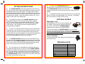
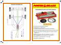
TRAILER SCHEMATIC
THE
POWER
STOP
BRAKE
THE 3 IN 1 BRAKING SOLUTION FOR TRAILERS AND TOWED IMPLEMENTS
POWERBRAKE INSTALLATION MANUAL
Failsafe Spring Loaded Braking System.
Independent to working brakes.
Automatically Applies Brakes in the Event of a Breakaway.
Automatically Applies Hand-Brake when detached from Tractor Unit.
Emergency Stop Unit can be fitted to the Tractor where necessary
(40+ km/hr).
Brakes in the Event of the Tractor Stalling on an Incline.
The POWERBRAKE can be easily fitted to most Trailers.
One Simple 12 Volt connection to Tractor Unit.
Extremely Low Maintenance.
FITTING INSTRUCTIONS
A. The POWER-BRAKE should be positioned on the main tow
bar with the pulley wheel side facing towards the brake levers and
axels and away from the towing hitch. The Pulley wheel should
preferably be placed between 800 mm and 2000 mm from the front
axel, and should also be in a position where the wire rope will not
be fouled by the chassis. There should be a minimum of 3 x 5 cm
welds on each side of the folded plate.
B. The hydraulic cylinder on the POWER- BRAKE must be
hydraulically attached to the existing working brake Hydraulic
line. This can be done by cutting the line and placing a “T” piece
fitting to the line, and bringing a 3/8" hose form this fitting direct
to the cylinder. This cylinder will now be charged when the
working brakes are applied.
C. The 3 pin 12 Volt plug and the CE top plug can now be wired
ensuring there is the correct amount of cable to reach the Tractor
socket. Excess wire should be avoided and all cable should be
secured with ties to prevent damage. Full care should be taken that
all connection are tight and secure. The 12 volt plug can be
connected supplying power to the solenoid valve.
D. The POWER- BRAKE cylinder can now be powered out by
pressing the brake pedal, this will extend the springs to a stretched
position. Once the POWER- BRAKE has been powered out to its
full (130 mm), there is no need to keep pressing the brake pedal,
as the 12 volt valve will now hold the cylinder in place.
E. The wire rope can now be attached to the brake disc lever
and passed through the eye on the front of the POWER- BRAKE.
It can now returned to the opposite side lever and clamped using
the “U” bolts supplied. Any excess wire rope should be trimmed, to
avoid damage .It is important that the wire rope is clamped when
the POWER-BRAKE cylinder is in the fully out position, and that all
slack has removed from the wire rope.
F. To check your POWER-BRAKE simply
disconnect the 12 Volt plug from the tractor socket.
The POWER-BRAKE cylinder should retract
sharply until the disc lever are fully pulled. The brakes are now
applied.
G. To release the brakes simply reconnect the 12 Volt plug and
press the Tractor unit brake pedal for 3-4 seconds. Your Brakes
are now off and your trailer is free to move.
OPTIONAL EXTRAS
EMERGENCY STOP
An EMERGENCY STOP kit is also available, this
unit needs no wiring and is simply plugged into
the tractor socket and the POWER-BRAKE is
plugged into the socket on the EMERGENCY
This unit will activate the POWER-BRAKE at any time when
pressed. This unit is supplied as an optional extra, however it is
recommended that this unit is used, in order to benefit from all the
aspects of the POWER-BRAKE.
12 VOLT SOCKETS
12 Volts sockets (Suit 3 pin plug) are also available for
older tractor units
TECHNICAL DATA
HYDRAULIC CONNECTIONS
3/8” B.S.P.
MINIMUM HYDRAULIC PRESSURE
70 BAR
VOLTAGE
12 VOLTS
AMPS
1.15 AMPS
LENGTH
70 CM
WIDTH
23 CM
HEIGHT
17 CM
WEIGHT
28 KG
PAINT
G.P.L.S. PRIMER