1
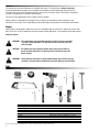
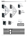
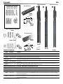
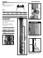
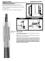
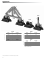
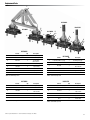
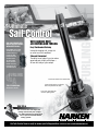
BATTCAR SWITCH SYSTEM
INSTALLATION MANUAL
18 mm
Installation Manual – Intended for specialized personnel or expert users
4679 11/14
Introduction
Safety precautions
2
Preassembly
Tools2
Parts
3-4
Sizing/sail modification/switch height
5
Top track length
6
Track length
6
Assembly—Slug-Mount Track
Cut top track to length
Check fit of mounting slugs and car
Install track Install switch
7
7
8-9
10 - 11
Assembly—Drill and Tap Track
Removing old track
Mount track to carbon mast
General instructions
Install switch
Install track
Install top stop
12
12
12
13
14 - 15
15
Commissioning
Loading headboard assembly
Loading cars
Attaching sail
Lazy Jacks
16
16
16
17
Operation
Raising sail
17
Sailmakers Instructions
Dimensions18
Installing headboard car assembly
18
Distance between attachment points
19
Setting reef points
19
Replacement Parts
Troubleshooting/Warranty
Please read these instructions carefully before installing, servicing, or operating the equipment.
This manual may be modified without notice. See: www.harken.com/manuals for updated versions.
PLEASE SAVE THESE INSTRUCTIONS
20 - 21
22
t
This manual gives technical information on installation and service. This information is destined exclusively
for specialized personnel or expert users. Installation, disassembling, and reassembling by personnel who are
not experts may cause serious damage to property, injury to users, or injury to those in the vicinity of the product.
If you do not understand an instruction, contact Harken.
The user must have appropriate training in order to use this product.
Harken accepts no responsibility for damage or harm caused by not observing the safety requirements and
instructions in this manual. See Limited Warranty, General Warnings, and Instructions at www.harken.com/manuals.
Purpose
Harken Battcars are designed to reduce the size of, or to completely drop the mainsail on a sailboat so wind has little
effect on the sail. Use of this product for other than normal sailboat applications is not covered by the limited warranty.
Safety Precautions
WARNING! This symbol alerts you to potential hazards that can kill or hurt you and others
if you don't follow instructions. The message will tell you how to reduce the
chance of injury.
CAUTION! This symbol alerts you to potential hazards that can hurt you and others if
you do not follow instructions. The message will tell you how to reduce the
chance of injury.
WARNING! Strictly follow all instructions to avoid potential hazards that can kill or hurt you
and others. See www.harken.com/manuals for General Warnings and Instructions.
Tools
1
2
4
3
5
7
9
8
1.Tape measure
2. Tape (slug mount)
3. Power drill (screwdriver)
4. Drill - 5 mm (7/32") (slug mount)
Drill - 4.2 mm (5/32") (drill/tap)
5. Phillips screwdriver (slug mount)
6. Hammer
7. Hacksaw
Mast-up installation: stepladder secured to the boat.
Work height: 2.13 m (7') above boom
10
  8. Center punch
  9. File
10. Putty knife (slug mount)
11. McLube® Sailkote™ dry lubricant
10-32 or 5 mm tap (drill/tap) – not shown
Transfer punch 5 mm (3/16") (drill/tap) – not shown
McLube is a registered trademark of McGee Industries, Inc. SailKote is a trademark of McLube, a division of McGee Industries.
2
11
6
PreassemblyParts
HEADBOARD CAR
(ASSEMBLY)
BATTEN CARS
WITHOUT RECEPTACLE
HC8537
HC7906HL
HC7906
INTERMEDIATE
CARS
HC7904HL
HC8537HL
SPARE CAR SCREWS
HC7905
HC7905HL
Important! Do not overtighten
screw and nut. Car will bind
and may warp permanently.
Cars
Part No.
HC7906
Description
Headboard car assembly
HC7905
Intermediate car
HC8537
Batten car
System
Low-load Consult sailmaker for quantity required.
10 mm threaded stud. Purchase batten receptacle separately.
HC7906HL Headboard car assembly
HC7905HL Intermediate car
HC8537HL Batten car
HC7904HL Batten car
Comments
Use regular headboard.
Use regular headboard. Uses low friction slider insert.
High-load
Consult sailmaker for quantity required. Uses Delrin® slider insert.*
10 mm threaded stud. Purchase batten receptacle separately. Uses low-friction slider insert.
12 mm threaded stud. Purchase batten receptacle separately. Uses low-friction slider insert.
*If receptacle is removed, do not mix base intermediate car with batten receptacle cars. See page 16.
Delrin is a registered trademark of E. I. du Pont de Nemours and Company or its affiliates.
3
PreassemblyParts
Switch (slug mount)
Track mounting kit (slug mount)
HC9106, HC9107, HC9108
HC9702, HC9703, HC9704
Switch (drill and tap)
Slug mount track
a
HC8800
HC8811
b
18 mm
11/16"
4 mm (5/32")
15 mm
19/32"
c
d
HC8800
HC8811
Switch mounting kit (slug mount)
HC8918
Drill and tap track
a
b
d
c
HC7827
HC9597
HC8919, HC8921
18 mm
11/16"
4 mm (5/32")
12.7 mm
1/2"
HC7827
Switch/Track (Slug Mount)
Part No.
Description
HC8798
Switch (short)
HC8799
Switch (long)
HC8918, HC8919
Switch mounting kit
HC8921
HC8800, HC8811 Track
HC9106, HC9107
Track mounting kit
HC9108
HC8798
HC8230
HC8799
HC10417
Comments
Length: 605 mm (2313/16"); 1 x switch; 2 x screw-pin endstops; 1 x flathead screw HFS320 (5 x 25 mm); 1 x upper stop H-42662
Length: 857 mm (333/4"); 1 x switch; 2 x screw-pin endstops; 1 x flathead screw HFS320 (5 x 25 mm); 1 x upper stop H-42662
(a) 3 x plastic locator screws HFS1170 (5 X 10 mm); (b) 3 x mounting slugs; (c) 1 x blue Loctite® adhesive; (d) 6 x flathead
screws HFS862 (5 x 10 mm). Purchase 1 kit for each section of track.
Length: 2051 mm (8013/16"); HC8800 hole spacing: 100 mm; HC8811 Hole Spacing: 50 mm;
Note: HC8811–order additional slugs and screws for 50 mm hole spacing.
(a) 19 x mounting slugs 19 mm (3/4"); (b) 1 x splice slug 67 mm (25/8"); (c) 2 x blue Loctite; (d) 21 x HFS1015 flathead screws
(5 x 20 mm).
(a) 10 x mounting slugs 19 mm (3/4"); (b) 1 x splice slug 67 mm (25/8"); (c) 1 x blue Loctite; (d) 10 x HFS1015 flathead screws
HC9702, HC9703
Extra slugs for HC8811
HC9704
(5 x 20 mm).*For sail headboard location at full hoist and when sail is reefed.
Switch/Track (Drill and Tap)—Use for masts without grooves or when slugs will not fit
Part No.
Description
Comments
HC8230
HC10417
Splice link
Switch
HC7827
Drill/tap track
HC9597
Drill/tap track
Joins HC7827 track sections; purchase two (2) for each section of track
Length: 857 mm (333/4"); Switch may be shortened to 605 mm (2313/16"); 1 x switch; 2 x screw pin endstops; 1 x upper stop H-42662
Length: 3000 mm (1181/8"); hole spacing: 100 mm; purchase stainless steel #10 (5 mm) screws separately (quantity 13.333
fasteners/meter of track). Do not use open-backed HC8800 or HC8811 track (requires mounting slugs). See page 12 for drill/tap
sizes and mounting instructions.
Length: 2000 mm (783/4"); hole spacing: 50 mm; purchase stainless steel #10 (5 mm) screws separately (quantity 13.333
fasteners/meter of track). Do not use open-backed HC8800 or HC8811 track (requires mounting slugs). See page 12 for drill/tap
sizes and mounting instructions.
Loctite is a registered trademark of Henkel AG & Company KGaA.
4
Preassembly
Sizing/Sail Modifications
Sizing
Note width and shape of switch and build
a platform on mast to mount.
Sizing
Make sure you have the correct size Battcar system for your boat.
Maximum sail area
Monohull
Multihull
Part No.
Headboard car
Part No.
Batten car
Part No.
Intermediate car
18 mm
41 m2 (450 ft2)
30 m2 (325 ft2)
HC7906
HC8537
HC7905
18 mm HL
56 m2 (600 ft2)
46 m2 (500 ft2)
HC7906HL
HC8537HL,
HC7904HL
HC7905HL
System
Track Length and Switch
Height Considerations
Allow 63 mm (21/2") below track to remove car.
Switch height is determined by the number
of cars required for system and the length
of the storage track.
INCORRECT
Note: Cars will not pass each other if
top of car is higher than “A” distance.
See chart below.
A
Switch
mm
in
HC8798
HC8218
286
111/4
HC8799
HC8219
540
211/4
Feeder
Gap
Switch
Locate switch so feeder gap does not
interfere with mounting slugs.
A
305 mm
12"
A
Cars can pass each other if not higher than “A”.
3852
Make sure track is longer than sail luff to
allow for stretch as sail ages. Track must
not block halyard exit.
5
Preassembly
Track Length
Layout system using charts to plan track location and lengths.
A
Top track—variable-length
Length
mm
in
Hole Spacing
mm
75
Total Track Length ___________
- SUM ___________
Top Track Length A ___________ X
Length
B
Standard track—slug-mount
Length
mm
2051
in
Hole Spacing
mm
8013/16
100
Standard track—drill and tap
Length
3000
1
Quantity
+
Hole Spacing
1181/8
=
75
X
Length
C
High-load track—slug-mount
Length
mm
in
2051
8013/16
Place in reefed headboard areas on larger boats.
High-load track—drill and tap
2000
=
Quantity
Hole Spacing
mm
50
783/4
+
50
X
Length
D
Switch—slug-mount
Length
mm
in
605
2313/16
857
333/4
Switch—drill and tap
Length
mm
in
605
2313/16
857
333/4
Short drill and tap switch is created by shortening switch.
=
Quantity
—
—
—
—
+
—
—
—
—
1
=
Quantity
SUM
2
Enter SUM above to
calculate Top Track Length.
6
Assembly—Slug-Mount
Cut Top Track to Length
10 mm (3/8")
Cut variable length top track.
Deburr cut.
Slightly round track corners that will
slide against mast.
Drill 5.5 mm (7/32") hole in cut end
of track for endstop.
Check Fit of Mounting Slugs and Car
Check fit
CORRECT
INCORRECT
Slug
Slug
Will Tighten
Will Not Tighten
Test track: Put mounting slug in groove,
track section on mast. Tighten with screw.
Make sure track will tighten to mast before
slug contacts track underside.
Mounting screw must be long enough for
mast groove. If necessary, purchase longer
screws.
67 mm (25/8") splice slug must fit feeder
opening. File opening to make longer.
Use halyard with retrieval line to run
67 mm (25/8") splice slug up mast to
check for burrs in groove.
CORRECT
10 or
more
INCORRECT
Slug
Slug
Warning! Some masts might not
allow enough screw engagement
into slug. Screws need a minimum
of 10 threads (turns) engaged to
hold track to mast.
Turn screw 360° at least 10 times after
threads engage slug.
Clear of Trysail Track?
Cars must clear storm trysail track.
Tracks often converge above spreaders.
42 mm (121/32")
Aft face of mast must be flat
or convex.
Mast prebend: Might require straightening
before installation.
7
Assembly—Slug-Mount
Install Track
Note: When using HC8811 track,
put slugs at 50 mm intervals at sail
headboard location at full hoist and
when sail is reefed. Otherwise skip holes
so slugs are at 100 mm hole spacing.
Full hoist
High-load track with
50 mm hole spacing.
Slip top track slugs into mast groove. Use
32 mm (3/4") mounting slug for top stop.
One drop blue Loctite® adhesive into each
splice slug hole.
Mast-up: Tape top stop slug even with top
of upper track. Tape other slugs in place.
Loctite is a registered trademark of Henkel AG & Company KGaA.
100 mm
omit every other
screw and slug.
50 mm
reef position.
High-load track with
50 mm hole spacing.
Thread 5 mm x 25 mm endstop screw
through endstop, track, and into slug.
Slide slugs into place with putty knife.
Loosely install 5 mm x 20 mm screws.
Mast-up: Remove tape. Tighten screw
to hold track.
Tip: Use putty knife to see if screws
are loose enough to slide in groove.
Remember: Tracks may stick when
reaching a spliced area on mast.
8
100 mm
omit every other
screw and slug.
Assembly—Slug-Mount
Hold full-length track piece up to mast.
Loosely install top screw.
Use putty knife to slide additional slugs
and splice slug into place. Loosely install
all nineteen 5 mm x 20 mm screws.
Install Track
Slide tracks up enough to fit next track.
Repeat until full-length tracks installed.
Mast-up: Hold upper tracks. Loosen screw
that holds tracks. Slide track up. If screws
bind in mast groove opening, loosen them
until track slides. Tighten new bottom
screw securely.
CAUTION! Do not let tracks
drop. Severe injury to hands
and/or fingers can result.
Loosen top screw. Slide top track up and
position next 2.05 m (6'87/8") track.
Slide 19 mounting slugs and splice slug
into mast groove.
Mast-up: Tighten bottom screw to
hold track.
Mast-up: Tape in place.
Loctite is a registered trademark of Henkel AG & Company KGaA.
Hold switch in place and make sure there
is 64 mm (21/2") below for loading cars.
One drop blue Loctite® adhesive into
each hole.
9
Assembly—Slug-Mount
Install Track
2
Back of
switch
Wide
section
Back of
switch
1
Narrow
section
Switch
bottom
Note location of bottom of switch and
storage tracks on mast. Refer to chart
below and put marks on mast at two (2)
or three (3) locations as shown. Make
sure slug is not located at feeder gap.
See page 6.
Part
No.
1
2
Flat slug: Load slug into mast so plastic
locator screw is at bottom.
Round slug: Load slug into mast so plastic
locator screw is at top.
Slug will fasten in “wide section” of slot.
Slug will fasten in “narrow section” of slot.
Tighten screw so slug stays in place at
location from chart above.
Check fit (round slug shown).
3
Switch length mm in mm in
mm
in
HC8798 603 mm (233/4) 79 31/8 219 85/8
—
—
HC8799 857 mm (333/4) 108 43/4 335 133/16 475 1811/16
Load slugs.
10
Assembly—Slug-Mount
Install switch over slugs so plastic locator
screw is through center hole.
Install Switch
Install connector screw using blue Loctite®
adhesive on screw. If necessary loosen
plastic locator screws.
Install screw in open slug hole using blue
Loctite adhesive.
Round slug will go below/flat slug above.
Remove plastic locator screw and replace with
mounting screw. Use blue Loctite adhesive.
Loctite is a registered trademark of Henkel AG & Company KGaA.
11
Assembly—Drill and Tap Mount
Part No.
General Instructions
Track
HC7827
Drill and Tap Sizes
mm
in
Drill
4.2 mm
5/32
Tap
5 x .80 mm
10-32
Comments
Length: 3000 mm (1181/8") Determine track length. See page 6.
Do not use HC8800 or HC8811 for drill and tap.
Track Fasteners
—
#10 (5 mm) flathead screws (not included); 131/3 fasteners/meter of track.
HC8230
Splice links. Order one per section of track.
HC8218
13/
HC7827
Switch
HC8219
Length: 605 mm (23
16")
(2313/
15
Switch: 605 mm
16") and storage track: 252 mm (9 /16").
Includes two screw-pin endstops and one upper stop.
18 mm
(11/16")
12.7 mm
(1/2")
Removing Old Track
Track on mast: Before removing, scribe pencil line down either side of track.
Track off mast: Attach string to mast to line up track during installation.
Mount Track to Carbon Mast
Consult with mast builder. Use suitable reinforcing plates when fastening track to carbon spars.
General Instructions
When mounting tracks, work using a straight edge reference line along mast. Do not let tracks vary from this line.
Tape track in place and center punch hole at bottom using a transfer punch.
Tip: Use low-speed drill with tap for cutting threads.
IMPORTANT! Use blue Loctite® adhesive instead of oil to lubricate tap.
Drill and tap single hole. Fasten track using
this single screw and align side-to-side
correctly. Use tape to hold in place.
Move up several holes and use transfer
punch to mark a second hole. Remove track.
Drill and tap hole.
Fasten track using two screws. Mark all remaining
holes using punch. Remove track. Drill and tap all
holes. Before installing track make sure upper
end has splice piece inserted.
Use threadlocker or epoxy to secure screw.
Specific instructions follow.
Loctite is a registered trademark of Henkel AG & Company KGaA.
12
4 mm (5/32")
HC7827
Assembly—Drill and Tap Mount
Install Switch
Insert splice link into switch track.
Using a plastic hammer, tap link into place.
Carefully align track and tape in place.
Use a transfer punch to mark a single hole.
Remove track. Drill and tap. Fasten with
single screw, no adhesive.
Realign track and mark a second hole using
transfer punch. Screw to mast using two
screws, no adhesive.
Mark remaining holes using transfer punch.
Remove track. Drill and tap remaining holes.
Mount switch to mast using threadlocker
or epoxy on screws as required.
13
Assembly—Drill and Tap Mount
HC10417 only
If shortening is required, use lines scribed on
switch track to indicate cut line. Make sure you
add 254 mm (10") to the upper track length.
Before mounting track, move endstops and
tether to new locations.
Tip: Move one at a time so you can see how
the line is run through the deadend hole.
Carefully align track. Use transfer punch to mark
holes. Drill, tap, and mount as directed above.
Important! Do not use epoxy or threadlocker
on screws because gate track is removed for
loading cars.
14
Install Track
Assembly—Drill and Tap Mount
Install Track
With track off mast, tap upper splice link
into track using procedures outlined above.
Follow general instructions (page 15)
for drilling and taping a single hole.
Always make sure tracks are aligned.
Install Top Stop
Use H-42662 as top stop.
15
Commissioning
Slug-Mount / Drill and Tap Mount
Lubricate cars onshore before loading.
Loading headboard assembly.
Loading cars.
Before bringing headboard assembly or
cars onboard boat, spray underbody track
slot (see arrows above) with a light coating
of McLube® Sailkote™ adhesive.
Note location of guide pegs on the feet
of cars. Guide pegs must be on same
side. Also cars must be loaded so pegs
are on inside of switch. Plain foot will be
on outside. If loading on left, plain foot
must be on left. If loading on right, plain
foot must be on right.
Pegs on foot of car guide it to correct
side. Pegs must be on inside.
WARNING! Overspray from
McLube will cause slippery
decks which can result in
loss of footing. Cover decks
or spray cars off boat.
Tip: Load cars on right track – plain foot
on right; left track – plain foot on left.
Tip: To load headboard car assembly,
angle headboard. Roll car onto tracks.
If necessary, remove headboard assembly.
IMPORTANT! When all cars are aluminum, do not mix
intermediate cars with other cars. See below.
Batten/headboard car
with low friction slider.
Hole
in hole
Hole
in Hole
Intermediate car
with Delrin® slider.
Hole in batten/
headboard car
Attaching sail
Important: Tighten until screw is even
with plastic insert in nut. Do not overtighten.
Car will bind and can warp permanently.
No hole in
intermediate car
If cars are off track and sail attaching hardware removed, do not mix intermediate base
cars with batten or headboard base cars. All cars have center hole in aluminum car. Low
friction sliders have a hole in the plastic visible from below and from hole in aluminum car.
Part No.
HC7904HL
HC8537HL
HC7906HL
HC7905YHL
Description
12 mm batten car
10 mm batten car
Headboard cars
Intermediate car
Slider Material
Low friction
Low friction
Low friction
Delrin
Hole in Plastic Slider
Yes
Yes
Yes
No
McLube is a registered trademark of McGee Industries, Inc. SailKote is a trademark of McLube, a division of McGee Industries.
Delrin is a registered trademark of E. I. du Pont de Nemours and Company or its affiliates.
16
If screw extends below
nut, it is overtightened.
Commissioning
Lazy Jacks
Use shockcord to hold Lazy Jacks open
so Battcars and battens will not catch on
them. This will also help stop slapping of
Lazy Jacks on sail.
Attach one end to lower spreader tips and
other to Lazy Jacks. Make sure shockcord
is long enough so boom can swing all the
way out without damaging spreaders.
HA RKEN
N E KR A H
Operation
Raising Sail
When raising, lowering, or reefing sail, make sure sail
is not loaded and cars pass easily through switch.
Watch sail and cars carefully. Stop hoisting immediately
if any binding is detected.
Possible sources of binding:
Cars bind at switch.
Reef line binds on fingers.
Reef line binds between car and switch.
Headboard binds on Lazy Jacks.
Correct the binding problem or luff sail before
resuming hoist. If forced, the fingers that extend
into switch may be damaged, requiring expensive
switch and car replacement. Lazy Jacks may also
be damaged.
IMPORTANT! Watch for
binding at switch. Stop
hoisting immediately.
Important! When using an electric halyard winch,
be especially vigilant when raising sail. Luff sail.
Watch for any binding or jamming at the switch.
Stop hoist immediately if any occurs.
If winch operator does not have a good view of switch
cars, station a crew member with a good view and
communication to operator.
Crew member must be able to communicate
problems to the winch operator immediately.
If there is a jam, damage to switch and cars will
occur very quickly resulting in expensive repairs
unless hoisting is stopped.
Important! Make sure reef outhaul loads are not applied
to cars when in switch. Damage to switch and cars will
occur, resulting in expensive repairs.
17
Sailmakers Instructions
B
C
Slug-Mount / Drill and Tap Mount
HC7906
HC7906HL
B
B
A
A
C
D
E
D
A
F
E
HC7905
HC7905HL
E
HC7904HL
HC8537HL
HC8537
D
Dimensions (measured from aft face of mast)
Part No.
HC7906
HC7905
HC8537
HC7906HL
HC7905HL
HC7904HL
HC8537HL
Description
Headboard car
Intermediate car
Batten car (10 mm stud)
Headboard car
Intermediate car
Batten car (12 mm stud)
Batten car (10 mm stud)
in
713/16
21/2
21/2
713/16
21/2
21/2
21/2
Part No.
HC7906
HC7905
HC8537
HC7906HL
HC7905HL
HC7904HL
HC8537HL
Description
Headboard car
Intermediate car
Batten car (10 mm stud)
Headboard car
Intermediate car
Batten car (12 mm stud)
Batten car (10 mm stud)
in
713/16
21/2
21/2
713/16
21/2
21/2
21/2
A
A
mm
198
63
63
198
63
63
63
mm
198
63
63
198
63
63
63
Mounted on slug mount track
B
C boltrope setback
in
mm
in
mm
11/4
31
29/16
65
11/4
31
29/16
65
11/4
31
29/16
65
11/4
31
29/16
65
11/4
31
29/16
65
11/4
31
29/16
65
11/4
31
29/16
65
Mounted on drill tap track
B
C boltrope setback
in
mm
in
mm
11/8
29
215/32
62
11/8
29
215/32
62
11/8
29
215/32
62
11/8
29
215/32
62
11/8
29
215/32
62
11/8
29
215/32
62
11/8
29
215/32
62
in
43/16
3/4
39/16
43/16
3/4
33/4
39/16
in
41/16
3/4
37/16
41/16
3/4
35/8
37/16
D
D
mm
106
19
90
106
19
95
90
E pin Ø
mm
6
6
6
6
6
6
6
F stud Ø
mm
—
—
10
—
—
12
10
mm
103
19
88
103
19
92
88
E pin Ø
mm
6
6
6
6
6
6
6
F stud Ø
mm
—
—
10
—
—
12
10
Installing Headboard Car Assembly
Headboard coupler attaches to standard headboards. Some headboard modification required.
Maximum thickness of headboard plates and sail: 14 mm (9/16").
64 mm
(21/2")
100mm
(4")
51 mm (2")
Min 9.5 mm
(3/8")
Coupler
attachment hole
Coupler attachment hole
Drill 11 mm (7/16") coupler attachment hole so center
is 101 mm (4") from top of headboard and 51 mm (2")
from front edge of boltrope.
Leave at least 9 mm (3/8") between front of headboard
plate and front edge of coupler attachment hole.
18
Halyard
attachment
hole
Halyard attachment hole
Use aft hole if headboard has two (2).
If not, drill second hole to accept halyard shackle pin.
Locate hole approximately 64 mm (21/2") aft of existing hole.
Sailmaker's Instructions
Slug-Mount / Drill and Tap Mount
Distance Between Attachment Points
Battens and intermediate cars placed at sailmaker's discretion.
Maximum distance between attachment points is 1.2 m - 1.35 m (4' - 4'6").
DIAGRAM A
Distance may be slightly greater. Contact Harken to discuss sail reshaping
to eliminate luff flutter.
Note: Adding battens may reduce stack height by eliminating luff cars.
INCORRECT
CORRECT
Loaded cars must
not ride in this area
while sailing.
DIAGRAM B
Setting reef points
Space reef points halfway between sail attachment points. Battens or reef points
may need to be moved. Diagram A.
Note: Batten fittings and cars cannot handle reefing outhaul or downhaul loads.
Transfer loads to a tack fitting. Diagram B.
Important! When setting up reef, make sure cars are not loaded when they are
in the switch area. If reef outhaul loads are applied to switch, switch and cars
will be damaged resulting in expensive repairs. Instruct operators not to raise
or lower sails with high loads on cars while in the switch area. Harken is not
responsible for damage to the switch area due to reef loads, or for raising or
lowering a sail when the sail is loaded.
19
Replacement Parts
6
5
2
HC8537
2
HC7906
3
4
HC7905
2
4
3
4
3
1
1
1
HC7906
HC7905
Part No.
Qty
Description
Part No.
1
H-40882
2
Car
Qty
1
H-40882
1
2
H-36184B
1
Car
Headboard receptacle
2
MP-0708
1
Delrin® roller
3
HFS1059
2
Screw SHCS M6 x 40 mm*
3
HFS1059
1
Screw SHCS M6 x 40 mm*
4
HFS852
2
Nut M6 locking
4
HFS852
1
Nut M6 locking
5
H-24211A
1
Clevis pin
6
HFS181
1
Cotter pin
HC8537
Part No.
Qty
1
H-40882
1
2
H-36490A
1
3
HFS1059
1
Screw SHCS M6 x 40 mm*
4
HFS852
1
Nut M6 locking
*SHCS = Socket head cap screw.
*SHCS = Socket head cap screw.
Delrin is a registered trademark of E. I. du Pont de Nemours and Company or its affiliates.
20
Description
Description
Car
Threaded stud
Replacement Parts
7
8
2
HC7904HL
HC7906HL
2
5
3
4
HC7905HL
2
4
6
HC8537HL
5
3
2
5
4
6
1
3
5
3
4
6
1
6
1
HC7906HL
1
Part No.
Qty
Description
1
H-59240 (w/MP-171 pegs)
2
Car with guide pegs
2
H-36184B
1
Headboard receptacle
HC7904HL
Part No.
Qty
Description
1
H-59240 (w/MP-171 pegs)
1
Car with guide pegs
2
H-37120A
1
Threaded stud
3
HFS1059
1
Screw SHCS
M6 x 40 mm*
3
HFS1059
2
Screw SHCS
M6 x 40 mm*
4
HFS852
2
Nut M6 locking
5
H-45064
4
Igus bushing
6
4913
4
Harken label
4
HFS852
1
Nut M6 locking
7
HFS181
1
Cotter pin 3/8 x 1.1"
5
H-45064
2
Igus bushing
8
H-24211A
1
Clevis pin
6
4913
2
Harken label
*SHCS = Socket head cap screw.
*SHCS = Socket head cap screw.
HC7905HL
HC8537HL
Part No.
Qty
Description
1
H-45530 (w/MP-171 pegs)
1
Car w/guide pegs
2
MP-0708
1
HFS1059
4
5
6
4913
3
Part No.
Qty
Description
1
H-59240 (w/MP-171 pegs)
1
Car with guide pegs
Delrin® roller
2
H-36490A
1
Threaded stud
1
Screw SHCS
M6 x 40 mm*
3
HFS1059
1
Screw SHCS
M6 x 4 mm*
HFS852
1
Nut M6 locking
4
HFS852
1
Nut M6 locking
H-45064
2
Igus bushing
5
H-45064
2
Igus bushing
2
Harken label
6
4913
2
Harken label
*SHCS = Socket head cap screw.
*SHCS = Socket head cap screw.
Delrin is a registered trademark of E. I. du Pont de Nemours and Company or its affiliates.
21
Problem
Probable Cause
Solution
Cut end of top or bottom track at joint.
Make sure the anodized end is toward the full-length track.
Track weight pulling tracks apart.
Tracks will come together when you loosen the
bottom screw and push the tracks up the mast.
Mounting slugs do not fit.
Slugs wrong size.
Different size slug required. Contact your dealer.
Mounting screws will not tighten.
Incorrect mounting slug used.
Different size slug required. Contact your dealer.
Slugs catching on mast splice.
Loosen screws slightly. If necessary have someone
at splice area to wiggle the slug past the splice.
Corners of cut track catching.
Use file to round off corners of track.
Mast has too much prebend.
Ease backstay and/or straighten mast.
Paint or other material clogging mast groove.
Clean out groove.
Ring was not pressed far enough.
Take sail to sailmaker.
Tracks do not butt up against each other.
Track will not slide up mast.
Sail headboard does not fit inside coupler.
Troubleshooting
Problem
Probable Cause
Solution
Slider damaged or missing.
Check and/or replace slider.
Too much friction.
Spray a small amount of McLube® Sailkote™ lubricant
in underbody track slot of all cars. If possible spray cars
off boat. If this is not possible, use a drop cloth to keep
overspray off deck. McLube will cause slippery decks
which can result in loss of footing (page 16).
Stud threaded too tightly into receptacle.
Back off threaded stud two turns.
Cap screws and nuts are overtightened on plastic cars.
Loosen nut until screw end is even with plastic in nut.
Can't raise sail, cars stop at switch.
Car loaded upside down. Pins in car on wrong side.
Remove car, flip it around and reload.
Nut on Battcar is not holding.
Locknut has been used too many times.
Get new 6 mm locknut.
Batten receptacle does not rotate.
Nuts are too tight.
Loosen nuts slightly.
Cars jam when raising sail.
Headboard or cars are catching on Lazy Jacks.
Use topping lift or rod vang and shockcord to pull
Lazy Jacks out to shrouds.
Sail will not go all the way up.
Sail is too tall or sheave is too far forward.
Have sail shortened or move sheave aft.
Vertical post or pin on batten receptacle bending.
Reef loads are being transferred to batten receptacle.
Transfer reef downhaul and outhaul loads to mast
or boom gooseneck.
Reef tack fitting will not reach reef hook.
Reef point too close to sail attachment.
Move intermediate car sail attachment.
Cars bind.
Delrin is a registered trademark of E. I. du Pont de Nemours and Company or its affiliates. Loctite is a registered trademark of Henkel AG & Company KGaA.
McLube is a registered trademark of McGee Industries, Inc. SailKote is a trademark of McLube, a division of McGee Industries.
Maintenance
Harken equipment is designed for minimal maintenance, but some maintenance is required for optimum and safest possible operation and to comply with
the Harken limited warranty. In general, the most important aspect of maintenance is to keep your equipment clean by frequently flushing with fresh water.
In corrosive atmospheres, stainless parts may show discoloration around holes, rivets, and screws. This is not serious and may be removed with a fine abrasive.
With the exception of winches, do not use grease unless specifically recommended in the instruction sheet.
Flush blocks thoroughly with fresh water. Periodically, disassemble the blocks and clean with detergent and fresh water. Lubrication is not required.
IMPORTANT! Exposure to some teak cleaners and other caustic solutions can result in discoloration of part and is not covered
under the Harken warranty.
Warranty
For additional safety, maintenance, and warranty information: www.harken.com/manuals or the Harken catalog.
22
Ultimate
Sail Control
HOW CAN I REDUCE HEEL
AND GET BETTER CONTROL
WITH A REEFED SAIL?
Harken MKIV roller reefing
and furling units solve the
inefficient shape of
reefed sails with
independent head
and tack swivels.
The independent
swivels allow the
middle to furl first,
flattening the sail
and reducing heel.
WITH HARKEN MKIV
JIB REEFING AND FURLING
Bob Grieser Photo
Easy Shorthanded Cruising
Instead of changing sails, simply furl
or unfurl to suit the conditions.
Safe and Convenient
The ability to reef makes it easy to reduce
speed and gain visibility off the bow—
all from the safety of your cockpit.
FURLING
Q&A
Small outer drums fit on narrow bows
9 rows of ball bearings cut friction
and evenly distribute the load
TOP 25 FURLING Q&A:
www.harken.com/usa
Large inner spool diameter
increases pulling power
TECH TIP #4
You can have total sail shape and
reefing control from your cockpit
by adding ball bearing genoa lead
cars to your low-friction Harken
furling system.
Our Tech Service Team is ready to answer your furling questions. Call 262-691-3320 or email [email protected]
Corporate Headquarters
N15W24983 Bluemound Rd, Pewaukee, WI 53072 USA
Telephone: (262) 691-3320 • Fax: (262) 701-5780
Web: www.harken.com • Email: [email protected]
Harken Australia Pty, Ltd.
1B Green Street, Brookvale, N.S.W. 2100, Australia
Telephone: (61) 2-8978-8666 • Fax: (61) 2-8978-8667
Web: harken.com.au • Email: [email protected]
Harken France
ZA Port des Minimes, BP 3064, 17032 La Rochelle Cedex 1, France
Telephone: (33) 05.46.44.51.20 • Fax: (33) 05.46.44.25.70
Web: harken.fr • Email: [email protected]
Harken Italy S.p.A.
Via Marco Biagi, 14, 22070 Limido Comasco (CO) Italy
Telephone: (39) 031.3523511 • Fax: (39) 031.3520031
Web: harken.it • Email: [email protected]
Harken New Zealand, Ltd.
158 Beaumont Street
Unit 11, Orams Marine Centre
Westhaven, Aukland, 1010, New Zealand
Telephone: (64) 9-303-3744 • Fax: (64) 9-307-7987
Web: harken.co.nz • Email: [email protected]
Harken Polska SP ZOO
ul. Rydygiera 8, budynek 3A, lokal 101, I piętro, 01-793 Warszawa, Poland
Tel: +48 22 561 93 93 • Fax: +48 22 839 22 75
Web: harken.pl • Email: [email protected]
Harken Sweden AB
Main Office and Harken Brandstore: Västmannagatan 81B
SE-113 26 Stockholm Sweden
Telephone: (46) 0303 61875 • Fax: (46) 0303 61876
Mailing address: Harken Sweden AB, Box 64, SE -440 30 Marstrand
Web: harken.se • Email: [email protected]
Harken UK, Ltd.
Bearing House, Ampress Lane, Lymington, Hampshire S041 8LW, England
Telephone: (44) 01590-689122 • Fax: (44) 01590-610274
Web: harken.co.uk • Email: [email protected]
Please visit: http://www.harken.com/locator.aspx
to locate Harken dealers and distributors
Printed in USA 4679 12/14