1
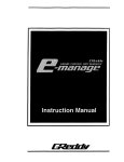
Field Installation Manual
of Frequency drive
for door gear AC 1 DC
Preambule ..........................................................................................Page 3
.......................................Page 5
Connection diagram of electronic card.......................................Page 6
Closing and Opening cycle .......................................................Page 7
How to use the Communication Tool ..........................................Page 9
. .
Description of Parameter..................................................................Page 13
Description of Variable (Inputs / Outputs) .....................................Page 21
Fault list and diagnostic ...............................................................Page 21
Presentation of V.V. V.F. door card OP15
Programme:
OP15 R 03 - 25/09/00
OP15 1 O0 - 10/04/00
Version 10 April 2003
This manual is deemed correct on going to press. It is linked to the program version shown on
the front page, however this version may evolve without influencing the contents of this manual,
which may in itself be changed without prior warning.
The information contained has been scrupulously checked. However AUTINOR declines al1
responsibility for error or omission.
Should you notice any discrepancy or unclear description, or if you have any suggestions, we
would appreciate your written comments (by mail or fax) to:
Société AUTINOR - Service Documentation
Z.A. Les Marlières
59710 AVELIN
n 133103-20-62-56-00
B [33] 03-20-62-56-41
IXI [email protected]
This manual is the property of AUTINOR, from whom it may be bought (at the above address). It
may however by freely copied in order to communicate information to those who might need it.
We can only authorise a complete copy, without addition nor removal of information
Where quotations are taken, the following at least must be noted:
-
the Company name of AUTINOR,
the program version to which it refers,
the number and date of the original edition.
ELECTROMAGNETIC COMPATlBlLlTY
Since the 1st January 1996 al1 lift installations are obliged to respect the essential requirements
of the European Directive 891336lCEE concerning Electromagnetic Compatibility (EMC).
The OP15 doors drive is only one component of an installation ; it is therefore not obliged to
show the c E:marking as stated in this directive. However in order to allow you to write your
declaration of conformitv, and according to professional rules, al1 AUTINOR controllers are
supplied with an engagement of conformity.
Your declaration of conformity can only rest on this engagement,
if the OP15 doors drive has been installed exactly as advised in this manual.
O Copyright 2002 AUTINOR All rights reserved
-*
OPIS
Field Installation Manual
Page 3
PREAMBULE
Check list of the electric risk link to the installation of the V W F door drive OP15:
When the V W F door drive is SUD DI^^^ on 230 VAC, TL, N and -L.
-=- 1.
The same voltage could be found on the opposite connector [X, Y, Z and b ] ,
The connector K I 5 in case of Slow down contact 1 or incremental encoder stay unisolated,
O
O
The connectors K3 and K4 are isolated from the main supply,
The connector SUB-D 9 points reste également non isolé, but the VEC03 box, give the
requested isolation,
In fact, in case of P313 board using (OP15 1P.C. Interface), this give the requested isola,tion.
In any case, ,the OV [ I l and 16V [2] outputs of the connector K5 couldn't be used for other
supply as the incremental encoder or Slow down contact supply.
Dimension, template and installation precausions:
L = 80, H = 155, D = 85, Weight = 400 g
Fixation by 2 oblongs of 4,5 mm (screw not supplied)
*
Slow down contacts: Specificity of the programme: OP15 R xx
lncremental encoder: Specificity of the programme: OP15 xx
-@op15
Field Installation Manual
Page 4
Installation precausions:
[ONLY WlTH THE PROGRAMME OP15 1
a
The mechanic link incremental encoder 1 Motor 1 Leaves must not show any slip.
THIS LlNK MUST BE LINEAR
It is imperative to respect this type of link because it is the encoder which gives the
door opening distance.
Link example:
Trainins:
Belt-driven
By endless screw
By direct coupling of the leafs
Charateristics and principle of the incremental encoder workincr:
For the encoder, the signal A and B should be quadrature. They are transmitted to
the following electronic box to be interpreated.
The output signals must respect the diagram below:
A
Chanel A ( ~ d d . 1 0- seg.
~ 6)
B Chanel B ( ~ d d . 1 -0seg.
~ 5)
@
, '!
op15
Field Installation Manual
Page 5
PRESENTATION OF THE VVVF DOOR CARD OP15.
The Electronic Door Control Unit OP15 has been designed to control 3 Phase AC motor up
to 0,3 kW, and D.C. motor
Software:
Programme Slow down contacts: ....... OP15 R 03 - 25/09/00
Programme lncremental Encoder: ..... OP15 1 00 - 10/04/00
The VVVF door drive only independently runs the slow down contact, due to the contact
which are connected directly or to the incremental encoder.
The opening and closing command are given from the controller which receive directly the
end limit contacts or by 'the intermediatly of the encoder which knows the exact position of the
leaves.
OPERATION OF 3 PHASE AC MOTOR
The frequency OP15 drive is supplied with a single phase voltage (230V AC) which is
transformed into a Variable Voltage Variable Frequency Voltage.
I1
1
CONTROLLER
OPEN LIMIT
1
CLOSE LlMlT
SCREEN CABLE
230 VAC
7 0,75 mm [ref AUTINOR : 34443
2
IL
SLOW DOWN
LlMlT ON
OPENING
SLOW DOWN
LlMlT ON
CLOSING
OR
INCREMENTAL
ENCODER
WARNING!!!
Positionning of the
coupling bar
'DELTA Connection'
On receiving the order from the controller to open the doors, the V.V.V.F. drive unit controls
the acceleration path of the motor up to a preset value.
The deceleration starts when the doors reach the slow down limit on opening OR when the
slow down distance is detected by the encoder.
When the controller gives the stopping signal, the drive will stop the motor.
The operation on closing sequence follows the above, the deceleration starts when the
doors reach the slow down limit on closing OR when the slow down distance is detected by the
encoder.
-@op15
Field Installation Manual
Page 6
CONNECTION DIAGRAM OF ELECTRONIC BOX.
-
The Open signal should be connected to Terminal connector K4 on - [2] and + [I. (24V or =)
The Close signal should be connected to Terminal connector K4 on - [4] and + 131. (24V or =)
The re-opening signal should be connected to Terminal connector K4 on - [6] and + 151. (24V or
=)
The Fire Service signal to do the Set-up speed on closing should be connected to Terminal K4
on - [8] and + 171. (24V or =).
-
-
1") For the Slow limit contacts: 2 choices:
A Slow down limit on opening which is connected to K5 on OV [I and CB 141.
A Slow down limit on closinq which is connected to K5 on OV [I and CA 131.
And a relav which ciive the re-opening, to K3 between [I and 121.
The box give equally 1 contact (NO) available on the terminal K3.
OR
An lncremental Encoder mounted on the door motor which is connected to K5
on OV [I, 16V 121, CA [3] and CB 141.
The OP15 deliver to the controller a simulation of the:
OPening End Limit contact (ELOP cou]) between [II and [2] to the K3
terminal,
And CLosing End Limit contact (ELCL [FCFE)) between [3] and [4] to the K3
terminal.
11 Proqramme:
1 OP15 R x x
I
Proqramme:
OP15 1 xx
NOTE:
The V W F 1 Motor link should be made with a SCREEN CABLE and as short as possible.
(The screen cable is not delivered but available as a spare part [ref AUTINOR: 34441)
Separate the conductors carrying large current and those
carrying electric information at low current.
-4%
Field Installation Manual
op15
page 7
Openinci and closinci cvcle.
Openinci cvcle (Proqramme version OP15 R 03 - 25/09/00)
When the opening command is given to the V W F control card, the opening cycle starts by
a small pre-acceleration Acc2 (address 009) which allows the smooth unlocking of the lock beak
(sabres). The motor will continue to accelerate ACCI (address 008) ~intilthe opening maximum
speed FMAXOP (address 000) is reached.
The deceleration DECEL (address OOA) starts when the door reaches the slow down limit
contact up to the speed limit on opening FMINOP (address 001). The Stop is given when the door
reaches the opening limit contact.
FMAXOP (Ad.000)
STOP POINT
(Ad.008
FMINOP
(Ad.OO1)
Acc2
(Ad.009)
I
I
I
I
l
I
I
I
I
I
I
I
I
1
OPENING
COMMAND
I
I
'
SLOWDOWN
COMMAND
Openinci cvcle (Proaramme version OP15 1 00 - 10/04/00)
When the opening command is given to the V W F control card, the opening cycle starts by
a small pre-acceleration Acc2 (address 009) which allows the smooth unlocking of the lock beak
(sabres). The motor will continue to accelerate ACCI (address 008) and stabilise itself when the
opening maximum speed FMAXOP (address 000) is reached.
The opening slow down distance DSDOP (address 04E) starts when the encoder
information is in receipt of the OP15 until the opening minimum speed FMINOP (address 001).
The stop is given when the door reaches the opening limit contact.
I
I
ELCL
End Limit contact on CLosing
I
I
I
I
l
I
I
l
I
Distance
OPENING
COMMAND
ELOP
End Limit contact on OPening
SLOWDOWN
COMMAND
-GY OPIS
Field Installation Manual
Closing cycle (Programme version OP15 R 03
Page 8
- 25/09/00)
When the opening command is given to the W F control card, the opening cycle starts by
an acceleration ACCI (address 008) until the maximum closing speed FMAXCL (address 004) is
reached.
The deceleration DECEL (address OOA) starts when the door reaches the slow down
closing contact until the minimum closing speed FMINCL (address 005). The Stop is given when
the door reaches the closing limit contact.
FMAXCL
(~d.004)
FMINCL
(Ad.005)
l
l
I
l
I
I
I
l
I
I
I
I
I
I
I
I
I
I
1
I
I
I
I
I
I
1
I
I
I
I
I
'4
SLOWDOWN
COMMAND
I
I
SCCL
_,_
- - DETERF ,
I
OCOP
1-
(Ad.018)
CLOSING
COMMAND
(Ad.006)
l
(Ad.01A)
Closinq cycle (Proqramme version OP15 1 00 - 10/04/00)
When the closing command is given to the VVVF control card, the opening cycle starts by
a acceleration ACCI (address 008) and stabilise itself when the closing maximum speed FMAXCL
(address 004) is reached.
The closing slow down distance DSDCL (address 04C) starts when the information of the
encoder is in receipt of the OP15 until the closing minimum speed FMINCL (address 005). The
stop is given when the door reaches the closing limit contact.
FMAXC
(Ad.004)
FMINCL
- - -
STOP POINT
-
(Ad.005)
I
I
I
l
1
ELOP
I
I
I
1
I
I
l
I
I
,
I
I
I
l
>PDIST( ~ d . o l *
1
i
CLOSING
COMMAND
ELCt
I
I
End Limit contact on OPening
Distance
End Limit contact on CLosing
SLOW DOWN
COMMAND
DSDOP
(Ad.04E)
1
P
SCCL
-1-
OCOP
1
(Ad.018)
-I'
(Ad.006)
I
I
*l
-@' OPI 5
Page 9
Field Installation Manual
HOW T 0 USE THE COMMUNICATION 1 DIAGNOSTIC TOOL
This chapter contains information which will allow you to adapt the V W F Door Drive to the
specific conditions of the lift on which it is installed.
This adaptation is con,trolledby parameters, which you can modify according to your needs using
the removable parameter 1 diagnostic communication device as described below in the paragraph
ACCESSING
THE PARAMETERS.
The parameters are memorized in a particular type of chip called an EEPROM 3 (or E2PROM)
which keeps the information even when the equipment is switched off.
Each parameter is linked to an abridqed name and an address which corresponds to the
position at which it is memorized in the EEPROM chip.
ACCESSING
THE PARAMETERS
As mentionned above, you can see and modify the parameters using the
parameterldiagnostic communication tool ; this consists of a 16 character LCD display with four
push buttons, which is connected to the OP15 box by a standard MalelFemale Sub-D 9 pt cable.
Standard MalelFemale
Sub-Dg pt cable
TO MODIFY THE VALUES
--
LTO
VALIDATE THE DATA
RESET TO ZERO
3
EEPROM stands for Electrically Erasable Programable Read Only Memory.
-@' OPI 5
Field Installation Manual
page 10
To access the ara met ers and Il0 informations
Po wer-up the equipment, the display shows:
l
OP151
....
...J...J
....
u
p
000
3,
OP15R
...J...J ....
....
1000
100
10
050 Hz
FMAXOP
1000
MODIF.100
CLEAR10VALID.1
1
MODIF. CLEAR VALID.
Each time you press 1 ,the value shown will increase by 1.
Each time you press 10 the value shown will increase by 10.
Each time you press 100 the value shown will increase by 100.
Each time you press 1000 the value shown will increase by 1000.
Choosinçi the lançiuaae
The parameterldiagnostic communication device is preset to the language of the destination « Pays
There are four options which appear at address 027 as follows:
D.
FRANCE, ENGLISH, DEUTSCH*, ESPAGNOL*. (* Not available at the moment)
Press twice button 10,
then 7 times button 1,
for address 027
,-
-
027
-.
-
Pays
FRANCE
Press both MODlF buttons
at the same time.
-
r
MDF
--
Pays
--
MODIF CLEAR VALlD
0
O
@
@
Press button 1 and choose the
required language.
--,
FRANCE
MDF
- -
Pays
ENGLISH
-
MODIF CLEAR VALlD
MODIF CLEAR VALlD
c-0-0-e
4li-e-0~
Register the required language by pressing both VALlD buttons at the same time
O27
Pays
1000
100
ENGLISH
10
~
1
1
MODIF. CLEAR VALID.
The language in our example is English
I
-%OPIS
Field Installation Manual
page 11
Transfer of the settinqs included in the VVVF toward the diaqnostic tool.
Press the 2 end buttons to make
« READ PARAMETERS >>
appear.
1-
REPSPARmETERs
-
Press the 2 end buttons
to return to normal mode
Validate by pressing the
« VALlD » buttons
..... Transfer
,
- -
-
-
READ Adr.
F8u
--
MODIF. CLEAR VALID.
-
-
1
-\
050 Hz
FMAXOP
O00
2
MODIF. CLEAR VALID.
e-0-0-e
-
MODIF. CLEAR VALID.
0-0-e-e
e-0-0-0
Note: You can memorise in the E2ROM of the box, the parameters of 4 VVVF door drive, respectively at the
addresses 00, 40, 80 or CO. For that, press the 2 end buttons than press « MODIF » button and modify the
right number to 00, 40, 80 or CO with the 1 O button than press « VALlD » to validate.
[
m
]
p
m
M
m
1000
100
10
1
1000
MODIF. CLEAR VALID.
100
10
1
1000
MODIF. CLEAR VAI-ID.
100
10
1000
1
m
o
-
10
1
00a@
0
0
e
T
0
Ex:
-
100
MODIF. CLEAR VALID.
MODIF. CLEAR VALID.
C o p y the V W F parameters a t
address 80 in the box
Transfer of the settincis included in the diaqnostic tool toward the VVVF.
Press the 2 end buttons,
you read,
« READ PARAMETERS D
Display
« WRlTE PARAMETERS ))
using button 1
Validate
b~ p ressing the
« VALID » button
..... Transfer
MODIF. CLEAR VAUD.
MODIF. CLEAR VAUD.
---
*
O Ob
press the 2 end buttons to
return to normal mode
MODIF. CLEAR VALID.
0
0 Oi
l
MODIF. CLEAR VALID.
6
6
0 0&
WARNING:
this operation overwrite on the paratneters inchded in the W F door drive
A
A
Note: You can transmit the VVVF parameters in the E2ROM of the box at addresses 00, 40, 80 or CO in the box
VEC03. For that, press the 2 end buttons, than on the button 1, to pass on « WRlTE » mode than modify the
right number at 00,40,80 or CO with the 10 button than press « VALlD » to validate.
[ T T ][W-]
1000
1W
10
1
1WO
100
10
1
1000
100
10
1
7
1WO
MODIF. CLEAR VALID.
MODIF. CLEAR VALID.
0
0
0
@
MODIF. CLEAR VALID
@--o-o
100
10
IWO
1
IW
10
1
MOMF. CLEAR VALID.
o-o-eTo
MODIF. CLEAR VALID.
0-0-tFia
Ex: C o p y t h e Parameters
memorised a t address
the
80 in the box to
VWF
To remind vourself of the address
If you forget the address you are changing, or the previous value
shown, just press both MODIF buttons
FMAXCL
040 Hz
MODIF. CLEAR VALID.
e3T%
4%op15
Field Installation Manual
page 12
To chancie the parameter in "decimal mode"
After selecting the required language (see previous page) you can access the parameters and change
them if required.
Reset the display by pressing
both CLEAR buttons
at the same time
--
r
O00
-
-
-
.--
-
7
FMAXOP
-
To change the Opening current
MCO, display address 002
by pressing button 1
050 Hz
002
-
-
MC0
Press both
MODlF buttons
at the same time
-
500 mA
MDF
--,
-
MODIF. CLEAR VALID.
500 mA 1
-
MC0
-
MODIF. CLEAR VALID.
MODIF. CLEAR VALID.
0
0
O
@
0
@
@
O
Press button 100 one time to
obtain the desired current.
Ex.: 600 mA
Register the new current by
pressing both VALlD button at
the same time
mm@-@
MODIF. CLEAR VALID.
MODIF. CLEAR VALID.
0
@
0
O
To chancie the parameters in "seqment mode"
ISDOP
7
7
Reset the display by pressing
both CLEAR buttons
at the same time
-
.
O00
FMAXOP
p
Display address OOD
by pressing button 1
Y
50 Hz
OOD
-
MODIF. CLEAR VALID.
Press both MODlF buttons
at the same time
- -
-
.
IRELOP
1
-
INV
1-
00000000
-
-
MDF
-
Press button 1
to activate the segment 5.
Register the new data in the
memory by pressing both VALlD
buttons at the same time.
-
,MDF
.
Bt5
-
ISDOP
-
MODIF. CLEAR VALID.
0
0
8
0
O
O
-
MODIF. CLEAR VALID.
0
0
0
8
Press button 10
to obtain the required segment.
Example: Inversion of the
slow down opening contact.
IRELOP
--@
@ C O
MODIF. CLEAR VALID.
O@
-@
- (-
BtO
-
-
-
OOD
INV
-
00100000
-,
MODIF. CLEAR VALID.
0-c-0-e
MODIF. CLEAR VALID.
0
O
@
@
+ segment 5 passes to 1
-@
op15
Field Installation Manual
page 13
DESCRIPTION OF PARAMETERS (In)
WARNING:
ALL REMAlNlNG OF PARAMETER SHOULD BE MADE
WlTHOUT DOOR COMMAND
L
Address
000 : FMAXOP.Frequency MAXimum on OPening
in Hz or V
We program the Maximum frequency on opening adjustable between 001 Hz to 080 Hz.
(001 V to 240 V in case of D.C. motor)
(See diagram OPENING CYCLE on page 7).
Address
001 : FMINOP.Frequency MlNimum on OPening
in Hz or V
We program the Minimum frequency on opening adjustable between 001 Hz to 020 Hz.
(001 V to 100 V in case of D.C. motor)
(See diagram OPENING CYCLE on page 7).
Address
002 : MCO.Maximum Current on Opening
in mA
We program the maximum current on opening [in mA].
This is the maximum current allowable on opening. This could be visualised at the address
12A (1-Capl). To this current reading, we added a percent (10 to 20%) and transmit it to the
address 002. If the current exceeds the programmed value, a fault code 02 will be generate. It will
clear after a set time.
Address 004 :
FMAXCL.Frequency MAXimum on CLosing
in Hz or V
We program the maximum frequency on closing adjustable between O01 Hz to 080 Hz.
(001 V to 240 V in case of D.C. motor)
(See diagram CLOSING CYCLE on page 8).
Address 005 :
FMINCL.Frequency MlNimum on Closing
in Hz or V
We program the maximum frequency on closing adjustable between 001 Hz to 020 Hz.
(001 V to 100 V in case of D.C. motor)
(See diagram CLOSING CYCLE on page 8).
Address 006 :
OCOP. Over-Current on re-OPening
in mA
I
We program the value of the over-current on re-opening [in mA].
This is the maximum current allowable on closing. This could be visualised at the address
12A (1-Capl). To this current reading, we added a percent (10 to 20%) and transmit it to the
address 006. If the current exceeds the programmed value, a re-opening will be excuted.
-@op15
Field Installation Manual
page 14
DESCRIPTION OF PARAMETERS (217)
Address 008 : ACCI. ACCeleration on Opening and Closing
in 1/10 second
We program the acceleretion on opening and closing (Decimal value in 1/10 s).
Write b
If the frequency used b
The Acceleration will be b
The acceleration is made on incrementation of the frequency (step 0.5 Hz every IOms),
than if the increment of acceleration equals 02, the starting frequency equals O Hz and the
frequency to reaches equals 50 Hz.
Address 009 : A c c ~ACCeleration
.
on pre-opening
in 1110 second
We program the acceleration on pre-opening (Set-up speed).
The pre-opening has the function of permitting the progressive action of unlocking system.
The pre-opening acceleration is made by incrementing the frequency to 0.5 Hz every IOms, it
substitutes itself at the acceleration during the begining of the door opening ACCI to permit a
progressive action on the unlocking system. It is not used if the minimum frequency on opening
FMINOP (page 13) is reached or if the closing slow down contact is made again, in this case, we
are using the acceleration ACCI.
Address OOA :
DECEL. DECELeration
in 1/10 second
[ONLY WTH THE PROGRAMME OP15 R
We program the DECELeration on opening et closing (Decimal value in 1/10 s).
The acceleration is made on incrementation of the frequency (step 0.5 Hz every IOms),
than if the increment of acceleration equals 02, the starting frequency equals O Hz and the
frequency to reaches equals 50 Hz.
The deceleration is made on decreasing the frequency (step 0.5 Hz every IOms), than if
the increment of deceleration egal 02, the starting frequency equals 50 Hz and the frequency to
reaches equal O Hz.
Write b
If the frequency used b
The Deceleration will be b
Address OOB :
F INH. Frequency INHibition
in Hz or V
We program the forced closing speed in nudging. It's the set-up speed adjustable between
001 Hz to 020 Hz. (001 V to 100 V in case of D.C. motor)
When the fireman function is activated, the safety knuckle contact or door re-open button
and the photocell contact are inhibited, that's why the closing is made on set-up speed.
-a
OPIS
Field Installation Manual
page 15
DESCRIPTION OF PARAMETERS (317)
Address
OOC : MID.Maximum lntegrator Duration
in second
We program the maximum duration door integrator
MID mini
MID maxi
WARNING:
If MID = 000,
NO INTEGRATOR
It is the maximum duration on opening or closing command.
If the programmed value is too high, the fault 22 appaers. (see page 21)
Address
1
1
OOD : IN!/
lnversion
[ONLY WlTH THE PROGRAMME OP15 IR XX]
Bits 2, 3,4,7 : Not used
Bit 6 : ISDCL inversion Slow Down Contact on Ciosing
'OODINV 01OOO@
-
lndicate the state of the slow down contact on closing.
The bit is at 1 when the contact is a NC contact.
The bit is at O when the contact is a NO contact.
1
--
Bit 5 : ISDOP inversion Slow Down contact on Opening
-1
-
OODI N V~ O I ~ & ~ O ~
-
-
lndicate the state of the slow down contact on opening.
The bit is at 1 when the contact is a NC contact.
The bit is at O when the contact is a NO contact.
1
Bit
1 : IRELCL inversion Relay End Limit on CLosing
lndicate the state of the end limit contact on closing.
The bit is at 1, the relay does paste.
The bit is at 0, the relay doesn't paste.
1
Bit
0 : IRELOP Inversion Relay End Limit on Opening
lndicate the state of the end limit contact on opening.
The bit is at 1, the relay does paste.
The bit is at 0, the relay doesn't paste.
Address OOF : AUTOTC. AUTOmatique Time Cycle
in second
We program the Automatic time to make a cycle including opening / closing /Stop time
(QFactory Specificity (DEPARTMENT R&D))
Address 011 : TPT. Transistor Pause Time
in ps
Factory adjustment (value in p ) , it's the 'Transistor pause time' (« temps mort ») of
commuting between the upper 1.G.B.T and lowest 1.G.B.T (4 ps).
4% op15
Field Installation Manual
page 16
DESCRIPTION OF PARAMETERS (417)
r
Address 013 : TT, Torque applied to .the door motor
without unit
We program the torque applied to the motor on opening an d closing.
The value is adjustable between 00 (smallest) and 30 (highest).
.
Address 014 :
Bits O,
1
Opf. Option
1, 2 , 3 , 4 , 6: Not Used
without unit
-1
-
Bit 7 :
DC MOT. D.C. MOTor
7
-
-
7
MDF Bt 7 DC MOT O
-
lndicate the state motor supply AC or DC
The bit is at 1 when the OP15 drive DC motor.
The bit is at O when the OP15 drive AC motor.
NOTE : when the bit 7 = 1, al1 the values visualised in Hz are now in V (Volts).
1
Bit 5 :
RESMOT. RESistive MOTor
This bit authorise the increasing of the torque and the voltage applied at lowest Frequency.
The maximum value of the TT parameter (Ad. 013 - page 16) will be now 40.
The bit is at 1 when the fonction is require.
The bit is at O otherwise.
Address 015 :
PDIST,Percent of DlStance
in %
[ONLYWTH THE PROGRAMME OP15 1 M
We program the percent of distance on accordance of the parameter SCCL (Ad. 018 page 16)
Address 018 : SCCL, Start Current of CLosing
in mA
We program the start current of closing (Full opening to Slow-down contact on opening).
Value max. 800 mA.
Address OlA :
DETERF,DETection re-opening between slow Down and Ciosing
in mA
[ONLY WlTH THE PROGRAMME OP15 R XX]
We program the re-opening detection between the Slow-down limit contact on closing an
the full closing. Value max. 800 mA.
Address 01F : CRESER,Current RESERves
in mA
We program the reserves of current added at OCOP (Add. 006 - page 13) corresponding
at the variation current admissible for each door on floor (depend on the friction)
-aop15
Field Installation Manual
pane 17
DESCRIPTION OF PARAMETERS (517)
Address
e
020 : DIST, Distance
in %
We program the door opening distance, it's the top number of the encoder to open the
door.
Address 024 :
COMPOP, COMPensation on OPening
in %
[ONLY WlTH THE PROGRAMME OP15 1 X X ]
We program the compensation on openinq movement allowed to correct the deceleration
in case of " Door shocks "
Address 025 :
COMPCL, COMPensation o n CLosing
in %
[ONLYWlTH THE P R O ( j W M E 8 P l s 1 X X ]
We program the compensation on closinq movement allowed to correct the deceleration in
case of " Door shocks "
Address
027 : Pays, Language.
At this address can be programmed the language to be used on the VEC03 programming tool.
Possible Choice:
Address 028
France, English*, Deutsch*, Espatïol * (*Not available at the moment)
t0 031 : PileDef, Fault List
At this address can be read the next 10 faults memorised by the W F door drive.
At the address 028 we found the last fault and at the address 032 the oldest fault registered.
BEFORE LEAVING THE SITE, SET THE FAULT LIST BACK TO 00. IN THIS WAY YOU
CAN KEEP BETTER TRACK OF ANY BREAKDOWNS.
Address 034 :
NST, Number of STarts. =>
OOOOOOOO
At this address, can be read the number of starts carried out by the VVVF Door drive on opening
or closing movement.
-@"op15
Field Installation Manual
page 18
DESCRIPTION OF PARAMETERS (617)
Address 042 :
Bit 7 :
REG
REGLE Automatic set-up of the door
Process: Switch the 7 at 1 then VALID.
The operator is on automatic set-up, it make the differents cycles, on closing and opening,
the bits O, 1, 2, 3, 4, 5 pass on ,the state O to 1 then the whole bits are reset at O.
Press tirne' button Io
and 2 times button 1
for address 042
[;OU
1000
100
10
1
MODIF. CLEAR VALID.
0-07e
Address 044 :
Press 7 times button 10 to
display REGLE
then 1 time on 1
Press both MODIF buttons
at the same time
1000
'[
100
10
MODIF. CLEAR VALID.
1
66OO
BU
MDF
1000
100
10
.. .
/(
1
REOLE
O
1
The process start when
MODlF buttons are press at
the same time
l
m
1000
100
10
1
MODIF. CLEAR
MAXOP.frequency MAXimum on OPening
in 1110 Hz
We program the maximum frequency on opening in 1/10 of Hz.
We program the minimum frequency on opening in 1/10 of Hz.
Address 047 :
FINH,Nudging Closing Forced
in 1110 Hz
We program the forced closing speed in nudging. It's the set-up speed adjustable between
001 Hz to 020 Hz.
When the fireman function is activated, the safety knuckle contact or door re-open button
and the photocell contact are inhibited, that's why the closing is made on set-up speed.
'
-*
Field Installation Manual
op15
page 19
DESCRIPTION OF PARAMETERS (717)
Address 048 :
MAXCL,frequency MAXimum on CLosing
in 1/10 Hz
[ONLY WITH THE PROGRAMMFl OP15 1 XX]
[ATTENTION, THIS PARAMETER REPLACE THE PA&4METER0041
We program the maximum frequency on closing movement in 1/10 of Hz.
Address 04A :
MINCL,frequency MlNimum on CLosing
[ONLY WITH THE PROGRAMME OP15 1
in 1/10 Hz
~q
[ATTENTION, THIS PARAMETER REPLACE THE PARAMETER 0051
We program the minimum frequency on closing movement in 1/10 de Hz.
Address 04C :
DSDCL. Distance of Slow Down on CLosing
in nb.lmp Encoder
We program the slow down distance on closing.
Address 04E :
DSDOP,Distance of Slow Down on OPening
[ONLY M T H THE PROGRAMME OP15 1 XX]
We program the slow down distance on opening.
in nb.lmp Encoder
-*
Field Installation Manual
op15
page 20
PARAMETERS TABLE AND FACTORY VALUES
Factory values
ADDRESS
AC
O00
R
...
050 HZ
002
R
1
R
l
1
1
0
0
4
1
004
1-1
005
O40 Hz
R
l
O10 HZ
1 - 60011
[lem]
O09
...
OOC
]-[
OOD
011
013
014
11014
13
13
v
13
13
l
0400 mA
13
R
l
01.0 S
14
R
l
02.0 S
14
02.0 S
14
R
1
R
l
R
[ml
P
l3
1
-
v
MoToR
SPEClFlCATlONS
(m]
00s
Page
DC
13
MoToR
SPEClFlCATlONS
...
AC
R
R
OOA
v
MOTOR
SPEClFlCATlONS
0500 mA
1
O08
...
010 HZ
R
[[O061
O06
v
MoToR
SPEClFlCATlONS
[m]
001
0151-
l
DC
Finals Values
...
015 Hz
v
MOTOR
SPECIFICATIONS
14
030 S
15
00000000
15
R
l
04.0 pS
15
R
l
000
16
Op10 0 0 0 1
1
00000000
16
l
R = Slow down contacts (programme OP15 R 03 - 25/09/00)
16
I = lncremental (OPI 5 1 00 - IO/O~/OO)
-@
op15
Field Installation Manual
Factor- Values
ADDRESS
AC
018
page 21
-1
01A
1
DC
Finals Values
AC
1
Page
DC
R
l
0500 mA
16
R
l
0500 mA
16
01F
[m]
l
16
020
[[O20
0000]1
l
17
024
[[0-OMPOP0000jl
I
17
l
17
DlST
0251-1
027
034
(1027
[(034NST00000000]1
R
l
FRANCE
17
R
I
00000000
17
1
000000O0
18
042
] -O[ [
1
044
[044MAXOPoooo~
046
I
18
l
18
l
18
I
19
047
[
(
0
4
7
=
0
0
0
0
]
]
048
[[O48 MAXCL
04A
[m!
04c
04E
[
[
0
4
OOO~]]
y
d
[-*00001)
l
19
R
I
19
R
l
19
R = Slow down contacts (programme OP15 R 03 - 25/09/00)
I= lncremental (OPI 5 1 00 - 10/04/00)
-6% op15
page 22
Field Installation Manual
DEFINITION OF THE VARIABLES (113)
EXPLICANA TION OF THE INPUTS:
Address 100 :
1
1
Inp. Bits O to 7.
Bits 4,s.6 , 7 : Not used
Bit
3 : Nudging command
lndicate the state of the forced closing on nudging (Setup-up speed). d INH information
The bit is at 1 when the nudging command is activated.
The bit is at O otherwise.
1
Bit 2 : Re-opening command
lndicate the state of the re-opening command (if exist).
The bit is at 1 when the re-opening relay is activatedl.
The bit is at O otherwise.
1
~ i1t: Closing command
lndicate the state of the closing command.
The bit is at 1 when the closing command is activated.
The bit is at O otherwise.
Bit 0 : Opening command
lndicate the state of the opening command.
The bit is at 1 when the opening command is activated.
The bit is at O otherwise.
Address
Bits O,
10A : hp3, Bits O to 7.
1, 2, 3, 4 and 7 : Not used
Bit 6 : Slow down contact on closing
Bit 5 : Slow down contact on opening
- 1 OA~n~301000000
1
lndicate the state of the slow down contact on
closing.
The bit is at 1 when the contact is activated.
The bit is at O otherwise.
lndicate the state of the slow down contact on
opening.
The bit is at 1 when the contact is activated.
The bit is at O otherwise.
OR
Bit 6 : State of the beam A
;liGziGq
lndicate the state of the beam A on closing.
The bit is at 1 when the beam A is cut.
The bit is at O otherwise.
( Bit 5 : State of the beam B
,--
-
? 0Ainp300~oo~oo(p, l
Programme:
100 10,04#f,Q
-
lndicate the state of the beam B on opening.
The bit is at 1 when the beam B is cut.
The bit is at O otherwise.
-62% OPIS
Field Installation Manual
page 23
DEFINITION OF THE VARIABLES (213)
EXPLANATION OF THE OUTPUTS:
0
Address
Bits
1
I
101 : Ouf, Ouptputs O to 7.
[m
1 , 4 , 5 , 6 , 7: Not used
Bit 3 : Fault indicator on opening I closing.
lndicate the state of the fault indicator on opening or closing.
The bit is at 1 when the fault is activate.
The bit is at O otherwise.
Fault Information on Opening or Closing.
Bit 2 : Shunt Relay.
1
-
-
- -
101 Out 00001000
-
L
-
lndicate the state of the shunt relay of filtering capacitor charge.
The bit is at 1 when the capacitor is loaded.
The bit is at O otherwise.
Bit 0 : State of the re-opening relay
lndicate the state of the relay which gives the re-open signal.
The bit is at 1 when the relay is activated.
The bit is at O otherwise.
Address 110 : Fre, FREquency used
in Hz or V
At this address, can be read the Frequency used by the door operator.
In case of D.C. motor, the value read at this address corresponding neither at a Frequency
nor a Voltage (Specific conversion Table)
Address
1I A : V l l l ~ fMotor
, Voltage
in %
At this address can be read the voltage percent used by the door operator motor.
Address
122 : C-MOP,Current on Maximum OPening
in mA
[ONLYWlTH THE PROGFQAMMEOP15 R XX]
At this address can be read the maximum current on opening. Warning, this value must be
paste at the address 002 after you've carried the values read at the address 124, 126 and 128
(Closing currents).
Address 124 :
C-CLO1,Current Closing at the beginning
in mA
[ONLY WlTH THE PROGRAMME OP15 f? X X ]
At this address can be read the maximum current on closing at the beginning of closing.
4%.op15
Field Installation Manual
~ a n 24
e
DEFINITION OF THE VARIABLES (313)
Address 126 : C-cLO2, final Current CLosing
in mA
*
[ONLYWTH THE PROGRAMME OP18 R XX]
At this address can be read the maximum current on closing at the end of closing.
Address 128 : C-CL03, Current CLosing Maximum
in mA
[ONLY WlT'ti THE PROGRAMME OP15 R W(1
At this address can be read the maximum current on closing, when the door normaly work
on closing.
Address 12A :
1-Capl, Current measuring device 1
in mA
At this address can be read the information given by the current measuring devive, Those
should be transfer at the address 002 [MCO] page 13, 006 [OCOP] page 13,018 [SCCL] page 16
and OIA [DETERF] page 16
Closina Cvcle:
OP15 R xx
A
A
C-CL03
(Ad.128)
t
I
I
I
I
I
I
b
-&
op15
Field Installation Manual
page 25
Fault list and Diaqnostic.
The fault code list is found at addresses 028, 029, 02A, 02B, 02C, 02D, 02E, 02F, 030 and
031. At address 028 the most recent fault is recorded and at address 031 the oldest recorded
fault.
BEFORE LEAVING THE SITE, SET THE FAULT LIST BACK TO 00. IN THIS WAY YOU CAN
KEEP BETTER TRACK OF ANY BREAKDOWNS.
Remember:
If the display blinking, a fault is in progress. This fault can disappear after a time.
Fault 02:
,
,-
T
Jamming door on opening
-
The value of the nominal current on opening of the motor is over after a safety knuckle
detection.
This fault can disappear after a time and the operator automatically reset itself.
Fault 22:
The door closing time (delay) is over.
Verify the door integrator time (delay) (on page 15).
Fault 90:
Over-Current
Over-current as 1 Ampere.
In fact:
The motor is on short-circuit
The outputs X, Y, Z, of the W V F are on short-circuit
A command transistor is faulty