1
YASKAWA
Machine Controller MP2000 Series
Counter Module
CNTR-01 USER'S MANUAL
Model: JAPMC-PL2300-E
YASKAWA
MANUAL NO. SIEP C880700 27A
Copyright © 2005 YASKAWA ELECTRIC CORPORATION
All rights reserved. No part of this publication may be reproduced, stored in a retrieval system,
or transmitted, in any form, or by any means, mechanical, electronic, photocopying, recording,
or otherwise, without the prior written permission of Yaskawa. No patent liability is assumed
with respect to the use of the information contained herein. Moreover, because Yaskawa is constantly striving to improve its high-quality products, the information contained in this manual is
subject to change without notice. Every precaution has been taken in the preparation of this
manual. Nevertheless, Yaskawa assumes no responsibility for errors or omissions. Neither is
any liability assumed for damages resulting from the use of the information contained in this
publication.
Using this Manual
CNTR-01 indicates the counter module for the MP2000 series Machine Controller.
Please read this manual to ensure correct usage of the CNTR-01. Keep this manual in a safe place for future reference.
■ Graphic Symbols Used in this Manual
The graphic symbols used in this manual indicate the following type of information.
• This symbol is used to indicate important information that should be memorized or minor precautions,
such as precautions that will result in alarms if not heeded.
■ Indication of Reverse Signals
In this manual, the names of reverse signals (ones that are valid when low) are written with a forward slash (/) before
the signal name, as shown in the following example:
Notation Examples
• S-ON
= /S-ON
• P-CON
= /P-CON
■ Copyrights
• Microsoft, Windows, Windows NT, and Internet Explorer are registered trademarks of the Microsoft Corporation.
• Pentium is a registered trademark of the Intel Corporation.
• Other product names and company names are the trademarks or registered trademarks of the respective company. “TM”
and the ® mark do not appear with product or company names in this manual.
3
■ Related Manuals
Refer to the following related manuals as required.
Thoroughly check the specifications, restrictions, and other conditions of the product before attempting to use it.
Manual Name
4
Manual Number
Contents
Machine Controller MP2300 Communication
Module
User’s Manual
SIEPC88070004
Describes the functions, specifications, and application
methods of the MP2300 Communication Modules (217IF,
218IF, 260IF, 261IF).
Machine Controller MP900 Series
User's Manual
Ladder Programming
SIEZ-C887-1.2
Describes the instructions used in MP900/MP2000 ladder
programming.
Machine Controller MP
User's Manual
Motion Programming
SIEZ-C887-1.3
Describes the instructions used in MP900/MP2000 motion
programming.
Machine Controller MP900/MP2000 Series
MPE720 Software for Programming Device
User’s Manual
SIEPC88070005
Describes how to install and operate the MP900/MP2000
Series programming system (MPE720).
Σ Series SGM/SGD
User’s Manual
SIE-S800-26.3
Describes the Σ Series SERVOPACK models, specifications
and capacity selection methods.
Σ Series SGM/SGDB
User’s Manual
SIE-S800-26.4
Describes the Σ Series SERVOPACK models, specifications
and capacity selection methods.
Σ-II Series
SGMH/SGDM User’s Manual
SIEPS80000005
Describes the installation, wiring, trial operation, function
applications methods, maintenance, and inspection of the Σ-II
Series SERVOPACKs.
Σ-II Series
SGMH/SGDM User’s Manual
SIEPS80000015
Describes the installation, wiring, trial operation, function
applications methods, maintenance, and inspection of the Σ-II
Series SERVOPACKs.
Σ-III Series SGMS/SGDS
User’s Manual
SIEPS80000000
Describes the models, capacities, selection methods, ratings,
characteristics, diagrams, cables, peripheral devices, wiring,
panel installation, trial operation, adjustment, function
application methods, maintenance, and inspection of the Σ-III
Series SERVOPACKs and Servomotors.
Σ-III Series SGMS/SGDS
Digital Operator
Instructions
TOBPS80000001
Describes the operation methods of the JUSP-OP05A Digital
Operator.
Σ-III Series SGMS/SGDS
User’s Manual
For MECHATROLINK-II communications
SIEPS80000011
Describes the models, capacities, selection methods, ratings,
characteristics, diagrams, cables, peripheral devices, wiring,
panel installation, trial operation, adjustment, function
application methods, maintenance, inspection, and
MECHATROLINK communication of the ∑-III Series
SERVOPACKs and Servomotors.
Machine Controller MP900/MP2000 Series
Linear Servomotor Manual
SIEPC88070006
Describes the connection methods, setting methods, and other
information for Linear Servomotors.
Machine Controller MP900 Series
New Ladder Editor
Programming Manual
SIE-C887-13.1
Describes the programming instructions of the New Ladder
Editor, which assists MP900/MP2000 Series design and
maintenance.
Machine Controller MP900 Series
New Ladder Editor
User’s Manual
SIE-C887-13.2
Describes the operating methods of the New Ladder Editor,
which assists MP900/MP2000 Series design and maintenance.
Machine Controller MP900/MP2000 Series
User’s Manual
MECHATROLINK System
SIEZ-C887-5.1
Describes the distributed I/O Module for the MECHATROLINK Modules for MP900/MP2000 Series Machine Controllers.
Safety Information
The following conventions are used to indicate precautions in this manual. These precautions are provided to ensure
the safe operation of the MP2000 series and connected devices. Information marked as shown below is important for
the safety of the user. Always read this information and heed the precautions that are provided.
The conventions are as follows:
WARNING
CAUTION
Indicates precautions that, if not heeded, could possibly result in loss of life, serious
injury, or property damage.
Indicates precautions that, if not heeded, could result in relatively serious or minor injury,
or property damage.
If not heeded, even precautions classified under
CAUTION can lead to serious results
depending on circumstances.
PROHIBITED
Indicates prohibited actions. Specific prohibitions are indicated inside
For example,
MANDATORY
indicates prohibition of open flame.
Indicates mandatory actions. Specific actions are indicated inside
For example,
.
●
.
indicates mandatory grounding.
5
Safety Precautions
The following precautions are for checking products on delivery, storage, transportation, installation, wiring, operation,
maintenance, inspection, and disposal. These precautions are important and must be observed.
WARNING
• Before starting operation in combination with the machine, ensure that an emergency stop procedure
has been provided and is working correctly.
There is a risk of injury.
• Do not touch anything inside the MP2000 series.
There is a risk of electrical shock.
• Always keep the front cover attached when power is being supplied.
There is a risk of electrical shock.
• Observe all procedures and precautions given in this manual for trial operation.
Operating mistakes while the servomotor and machine are connected can cause damage to the machine or even
accidents resulting in injury or death.
• Do not remove the module, front cover, cables, connector while power is being supplied.
There is a risk of electrical shock.
• Do not damage, pull on, apply excessive force to, place heavy objects on, or pinch cables.
There is a risk of electrical shock, operational failure or burning of the MP2000 series.
• Do not attempt to modify the MP2000 series in any way.
There is a risk of injury or device damage.
• Do not approach the machine when there is a momentary interruption to the power supply. When
power is restored, the machine controller and the connecting devices may start operation suddenly.
Provide suitable safety measures to protect people when operation restarts.
There is a risk of injury.
• Do not allow installation, disassembly, or repairs to be performed by anyone other than specified
personnel.
There is a risk of electrical shock or injury.
■ Storage and Transportation
CAUTION
• Do not store or install the MP2000 series in the following locations.
• Direct sunlight
• Ambient temperature exceeds the storage or operating conditions
• Ambient humidity exceeds the storage or operating conditions
• Rapid changes in temperature or locations subject to condensation
• Corrosive or flammable gas
• Excessive dust, dirt, salt, or metallic powder
• Water, oil, or chemicals
• Vibration or shock
• Do not subject the MP2000 series to halogen gases, such as fiuorine, chlovine, bromine, and iodine,
at any time even during transportation or installation.
There is a risk of device damage or injury.
• Do not overload the MP2000 series during transportation.
There is a risk of injury or an accident.
6
■ Installation
CAUTION
• Never use the MP2000 series in locations subject to water, corrosive atmospheres, or flammable
gas, or near burnable objects.
There is a risk of electrical shock or fire.
• Do not step on the MP2000 series or place heavy objects on the MP2000 series.
There is a risk of injury.
• Do not allow foreign objects to enter the MP2000 series.
There is a risk of element deterioration inside, an accident, or fire.
• Always mount the MP2000 series in the specified orientation.
There is a risk of an accident.
• Do not subject the MP2000 series to strong shock.
There is a risk of an accident.
■ Wiring
CAUTION
• Check the wiring to be sure it has been performed correctly.
There is a risk of motor run-away, injury, or an accident.
• Always use a power supply of the specified voltage.
There is a risk of burning.
• In places with poor power supply conditions, take all steps necessary to ensure that the input power
supply is within the specified voltage range.
There is a risk of device damage.
• Install breakers and other safety measure to provide protection against shorts in external wiring.
There is a risk of fire.
• Provide sufficient shielding when using the MP2000 series in the following locations.
There is a risk of device damage.
• Noise, such as from static electricity
• Strong electromagnetic or magnetic fields
• Radiation
• Near to power lines
7
■ Selecting, Separating, and Laying External Cables
CAUTION
• Consider the following items when selecting the I/O signal lines (external cables) to connect the
MP2000 series to external devices.
• Mechanical strength
• Noise interference
• Wiring distance
• Signal voltage, etc.
• Separate the I/O signal lines from the power lines both inside and outside the control box to reduce
the influence of noise from the power lines.
If the I/O signal lines and power lines are not separated properly, malfunctioning may result.
Example
of Separated External Cables
外部配線の分離例
Steel
separator
鉄板製のセパレータ
Power
circuit
動力回路の
cables
ケーブル
General
control
circuit
一般制御回路
cables
のケーブル
Digital I/O
ディジタル
signal
入出力信号
cables
ケーブル
■ Maintenance and Inspection Precautions
CAUTION
• Do not attempt to disassemble the MP2000 series.
There is a risk of electrical shock or injury.
• Do not change wiring while power is being supplied.
There is a risk of electrical shock or injury.
■ Disposal Precautions
CAUTION
• Dispose of the MP2000 series as general industrial waste.
■ General Precautions
Observe the following general precautions
to ensure safe application.
• The products shown in illustrations in this manual are sometimes shown without covers or protective guards. Always
replace the cover or protective guard as specified first, and then operate the products in accordance with the manual.
• The drawings presented in this manual are typical examples and may not match the product you received.
• If the manual must be ordered due to loss or damage, inform your nearest Yaskawa representative or one of the
offices listed on the back of this manual.
8
Warranty
( 1 ) Details of Warranty
Warranty Period
The warranty period for a product that was purchased (hereafter called “delivered product”) is one year from the time
of delivery to the location specified by the customer or 18 months from the time of shipment from the Yaskawa factory,
whichever is sooner.
Warranty Scope
Yaskawa shall replace or repair a defective product free of change if a defect attributable to Yaskawa occurs during the
warranty period above. This warranty does not cover defects caused by the delivered product reaching the end of its
service life and replacement of parts that require replacement or that have a limited service life.
This warranty does not cover failures that result from any of the following causes.
1. Improper handling, abuse, or use in unsuitable conditions or in environments not described in product catalogs or
manuals, or in any separately agreed-upon specifications
2. Causes not attributable to the delivered product itself
3. Modifications or repairs not performed by Yaskawa
4. Abuse of the delivered product in a manner in which it was not originally intended
5. Causes that were not foreseeable with the scientific and technological understanding at the time of shipment from
Yaskawa
6. Events for which Yaskawa is not responsible, such as natural or human-made disasters
( 2 ) Limitations of Liability
1. Yaskawa shall in no event be responsible for any damage or loss of opportunity to the customer that arises due to
failure of the delivered product.
2. Yaskawa shall not be responsible for any programs (including parameter settings) or the results of program execution of the programs provided by the user or by a third party for use with programmable Yaskawa products.
3. The information described in product catalogs or manuals is provided for the purpose of the customer purchasing
the appropriate product for the intended application. The use thereof does not guarantee that there are no infringements of intellectual property rights or other proprietary rights of Yaskawa or third parties, nor does it construe a
license.
4. Yaskawa shall not be responsible for any damage arising from infringements of intellectual property rights or other
proprietary rights of third parties as a result of using the information described in catalogs or manuals.
9
( 3 ) Suitability for Use
1. It is the customer’s responsibility to confirm conformity with any standards, codes, or regulations that apply if the
Yaskawa product is used in combination with any other products.
2. The customer must confirm that the Yaskawa product is suitable for the systems, machines, and equipment used by
the customer.
3. Consult with Yaskawa to determine whether use in the following applications is acceptable. If use in the application
is acceptable, use the product with extra allowance in ratings and specifications, and provide safety measures to
minimize hazards in the event of failure.
• Outdoor use, use involving potential chemical contamination or electrical interference, or use in conditions or
environments not described in product catalogs or manuals
• Nuclear energy control systems, combustion systems, railroad systems, aviation systems, vehicle systems,
medical equipment, amusement machines, and installations subject to separate industry or government regulations
• Systems, machines, and equipment that may present a risk to life or property
• Systems that require a high degree of reliability, such as systems that supply gas, water, or electricity, or systems that operate continuously 24 hours a day
• Other systems that require a similar high degree of safety
4. Never use the product for an application involving serious risk to life or property without first ensuring that the system is designed to secure the required level of safety with risk warnings and redundancy, and that the Yaskawa
product is properly rated and installed.
5. The circuit examples and other application examples described in product catalogs and manuals are for reference.
Check the functionality and safety of the actual devices and equipment to be used before using the product.
6. Read and understand all use prohibitions and precautions, and operate the Yaskawa product correctly to prevent
accidental harm to third parties.
( 4 ) Specifications Change
The names, specifications, appearance, and accessories of products in product catalogs and manuals may be changed at
any time based on improvements and other reasons. The next editions of the revised catalogs or manuals will be published with updated code numbers. Consult with your Yaskawa representative to confirm the actual specifications
before purchasing a product.
10
CONTENTS
Using this Manual - - - - - - - - - - - - - - - - - - - - - - - - - - - - - - - - - - - - - - - - - - - - - - - - - - - - - - Safety Information - - - - - - - - - - - - - - - - - - - - - - - - - - - - - - - - - - - - - - - - - - - - - - - - - - - - - - Safety Precautions - - - - - - - - - - - - - - - - - - - - - - - - - - - - - - - - - - - - - - - - - - - - - - - - - - - - - Warranty - - - - - - - - - - - - - - - - - - - - - - - - - - - - - - - - - - - - - - - - - - - - - - - - - - - - - - - - - - - - -
3
5
6
9
1 Mounting Optional Modules on Machine Controller - - - - - - - - - - - - - - - - - - - - -13
1.1 CNTR-01 Module Applicable Machine Controllers - - - - - - - - - - - - - - - - - - - - - - 14
1.2 Mounting/Removing Option Modules on Machine Controller - - - - - - - - - - - - - - - 14
1.2.1 Mounting Option Modules - - - - - - - - - - - - - - - - - - - - - - - - - - - - - - - - - - - - - - - - - - - - - - - - - 14
1.2.2 Removing Optional Modules- - - - - - - - - - - - - - - - - - - - - - - - - - - - - - - - - - - - - - - - - - - - - - - - 17
2 Specifications and Functions for CNTR-01 Module - - - - - - - - - - - - - - - - - - - - -19
2.1 CNTR-01 Module Specifications- - - - - - - - - - - - - - - - - - - - - - - - - - - - - - - - - - - 20
2.1.1 CNTR-01 Module Functions - - - - - - - - - - - - - - - - - - - - - - - - - - - - - - - - - - - - - - - - - - - - - - - - 20
2.1.2 CNTR-01 Module Appearance and External Dimensions - - - - - - - - - - - - - - - - - - - - - - - - - - - 20
2.1.3 Specifications - - - - - - - - - - - - - - - - - - - - - - - - - - - - - - - - - - - - - - - - - - - - - - - - - - - - - - - - - - 21
2.2 Pulse Counting Methods - - - - - - - - - - - - - - - - - - - - - - - - - - - - - - - - - - - - - - - - 24
2.2.1 Sign Method - - - - - - - - - - - - - - - - - - - - - - - - - - - - - - - - - - - - - - - - - - - - - - - - - - - - - - - - - - - 24
2.2.2 UP/DOWN Method - - - - - - - - - - - - - - - - - - - - - - - - - - - - - - - - - - - - - - - - - - - - - - - - - - - - - - 24
2.2.3 Pulse A/B Method - - - - - - - - - - - - - - - - - - - - - - - - - - - - - - - - - - - - - - - - - - - - - - - - - - - - - - - 25
2.3 Counter Modes- - - - - - - - - - - - - - - - - - - - - - - - - - - - - - - - - - - - - - - - - - - - - - - 26
2.3.1 Reversible Counter - - - - - - - - - - - - - - - - - - - - - - - - - - - - - - - - - - - - - - - - - - - - - - - - - - - - - - 26
2.3.2 Interval Counter - - - - - - - - - - - - - - - - - - - - - - - - - - - - - - - - - - - - - - - - - - - - - - - - - - - - - - - - 27
2.3.3 Frequency Measurement Counter - - - - - - - - - - - - - - - - - - - - - - - - - - - - - - - - - - - - - - - - - - - - 28
2.4 Counter Functions - - - - - - - - - - - - - - - - - - - - - - - - - - - - - - - - - - - - - - - - - - - - 29
2.4.1 Outline of Counter Function - - - - - - - - - - - - - - - - - - - - - - - - - - - - - - - - - - - - - - - - - - - - - - - - 29
2.4.2 Setting the Counter Fixed Parameters - - - - - - - - - - - - - - - - - - - - - - - - - - - - - - - - - - - - - - - - - 30
2.4.3 Setting the I/O Data - - - - - - - - - - - - - - - - - - - - - - - - - - - - - - - - - - - - - - - - - - - - - - - - - - - - - - 33
2.5 Counter Function Details - - - - - - - - - - - - - - - - - - - - - - - - - - - - - - - - - - - - - - - - 38
2.5.1 A/B Pulses Counting Mode- - - - - - - - - - - - - - - - - - - - - - - - - - - - - - - - - - - - - - - - - - - - - - - - - 38
2.5.2 Mask of Calculation by C-Pulse
- - - - - - - - - - - - - - - - - - - - - - - - - - - - - - - - - - - - - - - - - - - - 38
2.5.3 Count Disable - - - - - - - - - - - - - - - - - - - - - - - - - - - - - - - - - - - - - - - - - - - - - - - - - - - - - - - - - - 38
2.5.4 Calculating Preset - - - - - - - - - - - - - - - - - - - - - - - - - - - - - - - - - - - - - - - - - - - - - - - - - - - - - - - 39
2.5.5 PI Latch
- - - - - - - - - - - - - - - - - - - - - - - - - - - - - - - - - - - - - - - - - - - - - - - - - - - - - - - - - - - - - 40
2.5.6 Coincidence Output/Coincidence Interrupt - - - - - - - - - - - - - - - - - - - - - - - - - - - - - - - - - - - - - 41
2.5.7 Ring Counter - - - - - - - - - - - - - - - - - - - - - - - - - - - - - - - - - - - - - - - - - - - - - - - - - - - - - - - - - - 43
2.5.8 Number of POSMAX Turns Preset
- - - - - - - - - - - - - - - - - - - - - - - - - - - - - - - - - - - - - - - - - - 43
2.5.9 Electronic Gear Function - - - - - - - - - - - - - - - - - - - - - - - - - - - - - - - - - - - - - - - - - - - - - - - - - - 44
2.5.10 Multipurpose Output Function - - - - - - - - - - - - - - - - - - - - - - - - - - - - - - - - - - - - - - - - - - - - - - 47
11
3 CNTR-01 Module Connections - - - - - - - - - - - - - - - - - - - - - - - - - - - - - - - - - - - 49
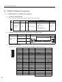
3.1 CNTR-01 Module Connections - - - - - - - - - - - - - - - - - - - - - - - - - - - - - - - - - - - -50
3.1.1 Specifications on Cable and Connector- - - - - - - - - - - - - - - - - - - - - - - - - - - - - - - - - - - - - - - - 50
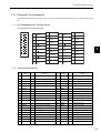
3.1.2 Connector Pin Arrangement - - - - - - - - - - - - - - - - - - - - - - - - - - - - - - - - - - - - - - - - - - - - - - - 51
3.2 CNTR-01 Connection Example - - - - - - - - - - - - - - - - - - - - - - - - - - - - - - - - - - - -52
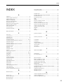
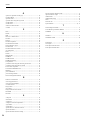
INDEX - - - - - - - - - - - - - - - - - - - - - - - - - - - - - - - - - - - - - - - - - - - - - - - - - - - - - - 53
Revision History
12
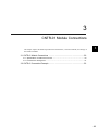
1
1
Mounting Optional Modules on
Machine Controller
This chapter explains on the MP2000 series Machine Controller, that can install the CNTR-01 Module, and mounting/removing the optional modules.
1.1 CNTR-01 Module Applicable Machine Controllers - - - - - - - - - - - - - - - - - - 14
1.2 Mounting/Removing Option Modules on Machine Controller - - - - - - - - - - - 14
1.2.1 Mounting Option Modules - - - - - - - - - - - - - - - - - - - - - - - - - - - - - - - - - - - - - - - - - - - -14
1.2.2 Removing Optional Modules - - - - - - - - - - - - - - - - - - - - - - - - - - - - - - - - - - - - - - - - - - - 17
13
1 Mounting Optional Modules on Machine Controller
1.2.1 Mounting Option Modules
1.1 CNTR-01 Module Applicable Machine Controllers
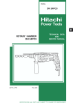
The table below lists the MP2000-series Machine Controllers on which the CNTR-01 Module can be mounted.
Name
MP
2200
Model
Base Unit
with 100/
200-VAC
Input
JEPMC-BU2200
Base Unit
with 24-VDC
Input
JEPMC-BU2210
MP2300
JEPMC-MP2300
Max. Number of
Applicable
Connecttable
CPU Version
Modules
30 modules
when using the
Remarks
Max. Number of CNTR-01 Modules that Can Be Connected when
using 4 racks (extended to the max-
CPU-01*1
31 modules
when using the
imum)*3
CPU-02*2
2 modules
Ver. 2.44 or
later
MP2100M
Applicable
MPE720
Version
JAPMC-MC2140 24 modules
Ver. 5.33 or
later
Can be mounted on an expansion
rack when mounting an expansion
I/F board MP2100MEX (model:
JAPMC-EX2200 and connecting an
expansion rack (can be used als as
the MP2200 base unit).
Max. Number of CNTR-01 Modules that Can Be Connected when
using 3 racks (extended to the maximum)*3
* 1. CPU Module for MP2200. Model: JAPMC-CP2200
* 2. CPU Module for MP2200. Model: JAPMC-CP2210, with one slot for CF card and one USB port
* 3. The Connection Module EXIOIF (Model: JAPMC-EX2200) is required between racks.
CNTR-01 Module cannot be mounted on the following MP2000-series Machine Controllers: MP2100, MP2500, and
MP2500M
1.2 Mounting/Removing Option Modules on Machine Controller
Use the following procedure to mount or remove Option Modules.
In the photos given here to explain the procedure, a Machine Controller MP2200 and an Option Module 217IF-01
are used. The procedure to mount a Counter Module CNTR-01 on a Machine Controller MP2300 or MP2100M is
the same as that to mount 217IF-01 on MP2200.
1.2.1 Mounting Option Modules
Use the followin procedure to mount an Option Module.
For the replacement of Option Module, refer to 1.2.2 Removing Optional Modules on page 17 to remove the Option
Module to be replaced.
( 1 ) Preparation
1.
Backup the Programs
Save the programs written to the Machine Controller in the personal computer using MPE720. (Right-click the
Counter Folder, and select Transfer - All Files - Dump from the pop-up menu.)
14
1.2 Mounting/Removing Option Modules on Machine Controller
2.
Remove the Machine Controller and Expansion Racks
a) For MP2300
Turn OFF the power supply and disconnect all the cables from the MP2300. Then, remove the MP2300 from the
panel or rack, and place it where there is sufficient space, such as working table.
b) For MP2200 and MP2100M
Turn OFF the power supply and disconnect all the cables from the expansion rack (MP2200 base unit) where the
Option Module to be replaced is mounted. Then, remove the expansion rack and place it on a place with sufficient space, such as working table.
1
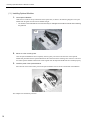
( 2 ) Removing Optional Cover
Use the following procedure if the optional cover is installed on the slot.
1.
Remove the battery cover.
Pull the notch on the side of the MP2000 series towards you to remove the battery cover.
2.
Remove the cover of Optional Module.
Insert the protruding part of the battery cover into the slot on top of the cover of Optional Module to unhook, as
shown in the diagram. Face the front of the battery cover towards you for this operation.
Unhook the bottom in the same way.
15
1 Mounting Optional Modules on Machine Controller
1.2.1 Mounting Option Modules
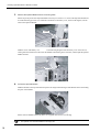
( 3 ) Installing Optional Modules
1.
Insert Optional Modules.
Guide rails are visible at the top and bottom of the Option Slot, as shown in the following diagram. Line up the
Module with the guide rail and insert the Module straight.
The FG bar on the inside bottom of the Unit Case may be damaged if the Module is inserted without following
the guide rail.
Guide
rail
2.
Mount on to the mounting base.
Once the Optional Module has been completely inserted, place your hand on the front face of the Optional
Module and push hard until the Optional Module has been inserted into the mounting base connectors. The front
face of the Optional Module and the hook will be aligned when the Optional Module has been installed properly.
3.
Install the panel of the Optional Module.
Place the hole on the bottom of the panel of the Optional Module onto the hook on the bottom of the MP2300.
This completes the installation procedure.
16
1.2 Mounting/Removing Option Modules on Machine Controller
1.2.2 Removing Optional Modules
( 1 ) Preparation
1.
Backup the Programs
Save the programs written to the Machine Controller in the personal computer using MPE720. (Right-click the
Controller Folder, and select Transfer - All Files - Dump from the pop-up menu.)
2.
Remove the Machine Controller and Expansion Racks
1
a) For MP2300
Turn OFF the power supply and disconnect all the cables from the MP2300. Then, remove the MP2300 from the
panel or rack, and place it on a place with sufficient space, such as working table.
b) For MP2200 and MP2100M
Turn OFF the power supply and disconnect all the cables from the expansion rack (MP2200 base unit) where the
Option Module to be replaced is mounted. Then remove the expansion rack and place it in a place with sufficient
space, such as working table.
( 2 ) Removing Optional Modules
1.
Remove the battery cover.
Pull the notch on the side of the MP2000 series towards you to remove the battery cover.
2.
Remove the panel of Optional Module.
Insert the protruding part of the battery cover into the slot on top of the panel of Optional Module to unhook, as
shown in the diagram. Face the front of the battery cover towards you for this operation.
Unhook the bottom in the same way.
17
1 Mounting Optional Modules on Machine Controller
1.2.2 Removing Optional Modules
3.
Remove the Optional Module from the mounting base.
Pull the top of the panel of the Optional Module towards you to remove it. A notch on the Optional Module will
be visible from the gap in the cover. Hook the round knob on the battery cover, shown in the diagram, into the
notch in the Optional Module.
Notch
Round knob
Hold the center of the battery cover as shown in the following diagram. Push the battery cover down and out,
rotating from the round knob to disconnect the Module and mounting base connectors, and then pull the Optional
Module forward.
Fulcrum
4.
Pull out the Optional Module.
Hold the Module on the top and bottom and pull it out straight. Hold the edges of the Module and avoid touching
the parts on the Module.
Put the removed Module into the bag that it was supplied with and store it in this bag.
The optional cover must be installed on the empty slot.
18
2
Specifications and Functions for
CNTR-01 Module
2
This chapter explains the detailed specifications and functions of the CNTR-01 Module.
2.1 CNTR-01 Module Specifications - - - - - - - - - - - - - - - - - - - - - - - - - - - - - - - 20
2.1.1 CNTR-01 Module Functions - - - - - - - - - - - - - - - - - - - - - - - - - - - - - - - - - - - - - - - - - - - 20
2.1.2 CNTR-01 Module Appearance and External Dimensions - - - - - - - - - - - - - - - - - - - - - -20
2.1.3 Specifications - - - - - - - - - - - - - - - - - - - - - - - - - - - - - - - - - - - - - - - - - - - - - - - - - - - - -21
2.2 Pulse Counting Methods - - - - - - - - - - - - - - - - - - - - - - - - - - - - - - - - - - - - 24
2.2.1 Sign Method - - - - - - - - - - - - - - - - - - - - - - - - - - - - - - - - - - - - - - - - - - - - - - - - - - - - - -24
2.2.2 UP/DOWN Method - - - - - - - - - - - - - - - - - - - - - - - - - - - - - - - - - - - - - - - - - - - - - - - - -24
2.2.3 Pulse A/B Method - - - - - - - - - - - - - - - - - - - - - - - - - - - - - - - - - - - - - - - - - - - - - - - - - -25
2.3 Counter Modes - - - - - - - - - - - - - - - - - - - - - - - - - - - - - - - - - - - - - - - - - - - 26
2.3.1 Reversible Counter - - - - - - - - - - - - - - - - - - - - - - - - - - - - - - - - - - - - - - - - - - - - - - - - -26
2.3.2 Interval Counter - - - - - - - - - - - - - - - - - - - - - - - - - - - - - - - - - - - - - - - - - - - - - - - - - - -27
2.3.3 Frequency Measurement Counter - - - - - - - - - - - - - - - - - - - - - - - - - - - - - - - - - - - - - - -28
2.4 Counter Functions - - - - - - - - - - - - - - - - - - - - - - - - - - - - - - - - - - - - - - - - 29
2.4.1 Outline of Counter Function - - - - - - - - - - - - - - - - - - - - - - - - - - - - - - - - - - - - - - - - - - -29
2.4.2 Setting the Counter Fixed Parameters - - - - - - - - - - - - - - - - - - - - - - - - - - - - - - - - - - - -30
2.4.3 Setting the I/O Data - - - - - - - - - - - - - - - - - - - - - - - - - - - - - - - - - - - - - - - - - - - - - - - - -33
2.5 Counter Function Details - - - - - - - - - - - - - - - - - - - - - - - - - - - - - - - - - - - - 38
2.5.1 A/B Pulses Counting Mode - - - - - - - - - - - - - - - - - - - - - - - - - - - - - - - - - - - - - - - - - - - -38
2.5.2 Mask of Calculation by C-Pulse - - - - - - - - - - - - - - - - - - - - - - - - - - - - - - - - - - - - - - - -38
2.5.3 Count Disable - - - - - - - - - - - - - - - - - - - - - - - - - - - - - - - - - - - - - - - - - - - - - - - - - - - - -38
2.5.4 Calculating Preset - - - - - - - - - - - - - - - - - - - - - - - - - - - - - - - - - - - - - - - - - - - - - - - - - -39
2.5.5 PI Latch - - - - - - - - - - - - - - - - - - - - - - - - - - - - - - - - - - - - - - - - - - - - - - - - - - - - - - - - - 40
2.5.6 Coincidence Output/Coincidence Interrupt - - - - - - - - - - - - - - - - - - - - - - - - - - - - - - - - -41
2.5.7 Ring Counter - - - - - - - - - - - - - - - - - - - - - - - - - - - - - - - - - - - - - - - - - - - - - - - - - - - - -43
2.5.8 Number of POSMAX Turns Preset - - - - - - - - - - - - - - - - - - - - - - - - - - - - - - - - - - - - - - 43
2.5.9 Electronic Gear Function - - - - - - - - - - - - - - - - - - - - - - - - - - - - - - - - - - - - - - - - - - - - -44
2.5.10 Multipurpose Output Function - - - - - - - - - - - - - - - - - - - - - - - - - - - - - - - - - - - - - - - - -47
19
2 Specifications and Functions for CNTR-01 Module
2.1.1 CNTR-01 Module Functions
2.1 CNTR-01 Module Specifications
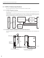
This section explains the function, appearance, and specifications of CNTR-01 module.
2.1.1 CNTR-01 Module Functions
The CNTR-01 module is equipped with 32 bits and 2 channels, and counts the pulse outputs of the pulse generator such
as rotary encoder.
CNTR-01 module can be mounted to the MP2300 option slot with up to 2 modules, and to the MP2200 base unit (when
4 units are connected) with up to 30 modules (when CPU-01 is used) or 31 modules (when CPU-02 is used), and to the
MP2100M and MP2100MEX expansion lack (when 3 lacks are connected) with 24 modules.
5V-differential type
interface
Pulse input processing
System
bus
12V-voltage type
interface
Shared
memory
CN1
Latch input
Coincidence output
DO output
Counter control
processing
2.1.2 CNTR-01 Module Appearance and External Dimensions
The following diagram shows the appearance of the CNTR-01, and the external dimensions when connecting the cable
connector.
(34)
Indicators (LED)
CNTR-01
RUN
ERR
CH1
CH2
CN1
I/O connector
(CN1)
(125)
(5)
Units: mm
(19.3)
CNTR-01 Module Appearance
20
(95)
External Dimensions when installing
the cable connector (side view)
2.1 CNTR-01 Module Specifications
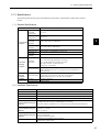
2.1.3 Specifications
The following table shows the general and hardware specifications, and the details of LED of the CNTR-01
module.
( 1 ) General Specifications
Item
Environmental
Conditions
Specifications
Ambient
Operating
Temperature
0 to 55 °C
Ambient Storage
Temperature
-25 to 85 °C
Ambient
Operating
Humidity
30% to 95% (with no condensation)
Ambient Storage
Humidity
5% to 95% (with no condensation)
Pollution Level
Pollution level 1 (conforming to JIS B 3501)
Corrosive Gas
There must be no combustible or corrosive gas.
Operating
Altitude
2,000 m above sea level or lower
Conforming to JIS B 3502:
10 to 57 Hz with single-amplitude of 0.075 mm
Vibration
Resistance
Mechanical
Operating
Conditions
2
57 to 150 Hz with fixed acceleration of 9.8 m/s2
10 sweeps each in X, Y, and Z directions
(sweep time: 1 octave/min)
Conforming to JIS B 3502:
Shock Resistance
Electrical
Operating
Conditions
Installation
Requirements
Peak acceleration of 147 m/s2 (15 G) twice for 11 ms each in the X, Y,
and Z directions
Noise Resistance
Conforming to EN 61000-6-2, EN 55011 (Group 1, Class A)
Power supply noise (FT noise): 2 Kv min., for one minute
Radiation noise (FT noise): 1 Kv min., for one minute
Ground
Ground to 100 Ω max.
Cooling Method
Natural cooling
( 2 ) Hardware Specifications
Item
Specifications
Description
Counter Module
Name
CNTR-01
Model Number
JAPMC-PL2300-E
Number of Channels
2
Input Circuits
(Can be switched using the
MPE720)
5-V differential: Max. frequency 4 MHz (RS422, non-isolated)
12V: Max. frequency 120 KHz (12 V, 7 mA current source mode input, photocoupler I/F)
Pulse Counting Methods
(Can be switched using the
MPE720)
A/B (×1, ×2, and ×4)
Up/Down(×1 and ×2)
Sign(×1 and ×2)
Counter Function
(Can be switched using the
MPE720)
Reversible counter mode
Interval counter mode
Frequency measurement mode
Coincidence Interrupt
Outputs to the CPU Module via the system bus.
Simultaneously outputs a DO.
21
2 Specifications and Functions for CNTR-01 Module
2.1.3 Specifications
Item
Specifications
Coincidence Output
2-point 24-VDC ± 20%, 50 mA current sink mode output, photocoupler interface
Response time: 1ms max. when OFF → ON, 1ms max. when ON → OFF
DO Output *
(Can be switched using the
MPE720)
2-point 24-VDC ± 20% , 50 mA current sink mode output, photocoupler interface
Response time: 1 ms max. when OFF → ON, 1 ms max. when ON → OFF
・Zone output
・Speed coincidence
・Frequency coincidence
PI Latch Output
DI: 2-point 24-VDC ± 20% souce mode input, photocoupler I/F
Response time: 30 μs max. when OFF → ON, 600 μs max. when ON → OFF
Phase-C: In 5-V differential input mode, the minimum ON pulse width is 125 ns.
In 12/24-V input mode, the minimum ON pulse width is 4.2 μs.
Latch input response time: 95 to 125 ns (response delay for pulse-A or B input
Connector
CN1: I/O connector
Indicators
RUN (green)
ERR (red)
CH1 (green)
CH2 (green)
Current Consumption
600mA at 5 V
Dimensions (mm)
125 × 95 (H × D)
Mass
Approx. 85 g
* Note that the DO output may turn ON at the moment the power supply turns OFF for 3 or 4 ms.
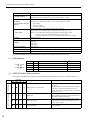
( 3 ) LED Indicators
RUN
ERR
CH1
CH2
Name
Color
RUN
Green
Normally operating
Status when Lit
Being stopped
Status when Unlit
ERR
Red
Malfunction occurs
Normally operating
CH1
Green
CH1 counter count value increments or decrements
No pulse input
CH2
Green
CH2 counter count value increments or decrements
No pulse input
( 4 ) CNTR-01 Module Status Indication
The CNTR-01 Module status is indicated by the combination of LED indicators as shown in the following table.
Normal Operation Status
Initialization
Status
22
Indication
RUN
ERR
CH1
CH2
CNTR-01 Module Status
Description
○
●
○
○
Status when power is turned ON
This is the status just after the Module’s power supply is
turned ON.
The ERR Indicator is turned OFF during initialization.
A boot error occurred if this LED status does not
change. The CNTR-01 firmware must be overwritten if
a boot error occurs.
○
○
○
○
Not defined
Indicates that the CNTR-01 Module has not been registered in Module Configuration. Register the Module in
the Module Configuration Window.
★
○
–
–
CPU being stopped
Indicates that the Machine Controller’s CPU is being
stopped. Execute a CPU RUN command to restore
normal operation status.
●
○
–
–
Operating normally
The Module is operating normally and pulse count is
being performed.
2.1 CNTR-01 Module Specifications
Status
Indication
RUN
★
CH1
–
Error
★
ERR
○
★
–
CNTR-01 Module Status
CH2
–
Description
Hardware error
1: 2: ROM error
3: RAM error
Hardware failure of the CNTR-01 Module occurred.
4: CPU error
Replace the Module.
6: Shared memory error
7: Counter ASIC error
(Number indicates the number of times
blinking.)
Software error
1: 2: Watchdog time timeout error
3: Address error (reading) exception
Software failure of the CNTR-01 Module occurred.
4: Address error (writing) exception
Replace the Module.
6: General illegal instruction exception
7: Slot illegal instruction exception
(Number indicates the number of times
blinking.)
2
z : Lit
{ : Unlit
: Blinking
-
: Not specified
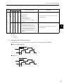
( 5 ) Minimum Width of Pulse Counting
Fill the following pulse width with the loose wire side of the standard cable (JEPMC-W2063--E).
■ Input 5-V Differential Input
250ns
125ns
62.5ns (A/B method)
■ Input 12V
8.4Ǵs
4.2Ǵs
2.1Ǵs (A/B method)
23
2 Specifications and Functions for CNTR-01 Module
2.2.1 Sign Method
2.2 Pulse Counting Methods
The CNTR-01 Module supports three pulse counting methods:
• Sign
• UP/DOWN
• A/B
This section describes the details on each pulse counting method.
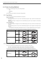
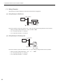
2.2.1 Sign Method
The count is incremented and decremended based on the polarity:
Polarity: Positive logic
When the pulse B input is at Low, the count is incremented by the pulse A input. (Positive in the frequency measurement*)
When the pulse B input is at High, the count is decremented by the pulse A input. (Negative in the frequency
measurement)
Polarity: Negative logic
When the pulse B input is at High, the count is incremented by the pulse A input. (Positive in the frequency measurement).
When the pulse B input is at Low, the count is decremented by the pulse A input. (Negative in the frequency measurement)
* For information on the frequency measurement, refer to 2.3.3 Frequency Measurement Counter on page 28.
The following table shows the pulse counting operations with different multiplications and polarities.
Pulse Counting Method
Polarity
Positive
logic
Sign (×1)
Negative
logic
Positive
logic
Sign (×2)
Negative
logic
UP Count (Forward)
Pulse A
Pulse A
Pulse B
LOW
Pulse A
Pulse B
HIGH
LOW
Pulse B
Pulse A
LOW
Pulse A
Pulse B
HIGH
Pulse B
Pulse A
Pulse A
Pulse B
DOWN Count (Reverse)
HIGH
Pulse B
Pulse A
LOW
LOW
Pulse B
2.2.2 UP/DOWN Method
The count is incremented ane decremented in the following way regardless of the polarity.
The count is incremented by the pulse A input. (Positive in the frequency measurement*)
The count is decremented by the pulse B input. (Negative in the frequency measurement)
The following table shows the pulse counting operations with different multiplications and polarities.
Pulse Counting Mode
Polarity
DOWN Count (Reverse)
Positive
logic
Pulse A
Negative
logic
Pulse A
Pulse A
Pulse B
Pulse B
UP/DOWN (×1)
24
UP Count (Forward)
Pulse B
Pulse A
Fixed at LOW or HIGH
Fixed at LOW or HIGH
Fixed at LOW or HIGH
Pulse B
Fixed at LOW or HIGH
2.2 Pulse Counting Methods
Pulse Counting Mode
Polarity
UP Count (Forward)
Positive
logic
Pulse A
Negative
logic
Pulse A
UP/DOWN (×2)
Pulse B
Pulse B
DOWN Count (Reverse)
Pulse A
Fixed at LOW or HIGH
Pulse B
Pulse A
Fixed at LOW or HIGH
Fixed at LOW or HIGH
Fixed at LOW or HIGH
Pulse B
±0 when the pulses A and B are input at a time.
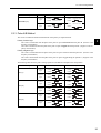
2.2.3 Pulse A/B Method
The count is incremented and decremented based on the polarity as explained below.
Polarity: Positive logic
The count is incremented when the phase of the pulse A input is advanced from the pulse B. (Positive in the
frequency measurement)
The count is decrmented when the phase of the pulse A input is lagged behind the pulse B. (Negative in the frequency measurement)
Polarity: Negative logic
The count is incremented when the phase of the pulse A input is advanced from the pulse B 0. (Positive in the
frequency measurement)
The count is decremented when the phase of the pulse A input is lagged behing the pulse B 0. (Negative in the
frequency measurement)
2
The following table shows the pulse counting operations with difference multiplications and polatiries.
Pulse Counting Mode
Polarity
Positive
logic
A/B (×1)
Negative
logic
Positive
logic
A/B (×2)
Negative
logic
Positive
logic
A/B (×4)
Negative
logic
UP Count (Forward)
DOWN Count (Reverse)
Pulse A
Pulse A
Pulse B
Pulse B
Pulse A
Pulse A
Pulse B
Pulse B
Pulse A
Pulse A
Pulse B
Pulse B
Pulse A
Pulse A
Pulse B
Pulse B
Pulse A
Pulse A
Pulse B
Pulse B
Pulse A
Pulse A
Pulse B
Pulse B
25
2 Specifications and Functions for CNTR-01 Module
2.3.1 Reversible Counter
2.3 Counter Modes
The CNTR-01 Module has three counter modes. The counter mode can be switched by setting the Fixed Parameter
Tab Page* of CNTR-01 Module Definition Window.
• Reversible counter
• Interval counter
• Frquency measurement
This section outlines each counter mode.
* Refer to 2.4.2 Setting the Counter Fixed Parameters on page 30.
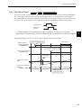
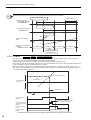
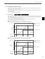
2.3.1 Reversible Counter
The count is incremented and decremented based on the pulse A and pulse B inputs.
The Count Disable and Count Preset functions are enabled when specified in the output data setting field* of I/O Data
Tab Page in the CNTR-01 Module Definition Window. Also the Mask of Calculation by C-Pulse can be selected to
prohibit counting while the pulse C is being input. The count value is stored in the input register (Counter Value) every
high-speed scan (or low-speed scan).
* Refer to 2.4.3 ( 3 ) Out Data Items on page 35.
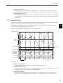
The diagram below illustrates an example of the reversible counter operation when the Counting Mask Using Pulse C
function is enabled)..
p3
2147483647㧔MAX㧕
p6
p2
㧔㧗㧕
p7
Count preset (1)
n3
Count preset (2)
n2
Counter
count
register
p1
p8
0
n6
Restarts counting
n1
Stops
counting
Stops counting
㧔㧙㧕
n4
n7
Count
Count
prohibited permitted
n5
Time㧔s㧕
2147483648㧔MIN㧕
Pulses A and B
Restarts
counting
p4
UP
Stop
UP
DOWN
UP
p5
Stop
DOWN
Stop
DOWN
Pulse C terminal
(positive logic)
Pulse C terminal
(negative logic)
Counter value
n1
Ts
n2
n3
n4
n5
n6
n7
Ts = scan setting (s)
<Explanation>
Counter value (IL
+4)
Stores sequentially the count value every scan (n1 to n7 in the above diagram)
Count preset (1) and (2)
As the Count Preset Request is executed at the positions p1 and p7 in the above diagram, the count values are
forcibly reset to the preset values p2 and p8.
26
2.3 Counter Modes
Overflow and Underflow
When the count value increments to the value MAX (p3), it is automatically reset to the value MIN (p4)
When the count value decrements to the value MIN (p5), it is automatically reset to the value MAX (p6).
Count disable/Count permit
The Counting Mask Using Pulse C function is enabled to stop counting while the pulse C is being input.
Also, executing the Count Prohibit command stops counting until the command is cancelled regardless of the
pulse C input.
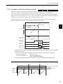
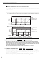
2.3.2 Interval Counter
The count is incremented and decremented based on the pulse A and B inputs, and the count value is stored in the input
register (Current Counter Count Value) every high-speed scan (or low-speed scan).
The count value is latched and the counter is reset when the pulse C is input (Inverval Latch). The latched data is
stored in the input register (Interval Data) every set scan.
2
The diagram below illustrates an example of the interval counter operation.
p2
2147483647㧔MAX㧕
p3
n7
m3
㧔㧗㧕
m1
m2
n1
n3
n2
n4
Counter
0
count
register
n6
m4
㧔㧙㧕
n5
Time (s)
2147483648㧔MIN㧕
Pulses A and B
p1
UP
DOWN
UP
p4
DOWN
UP
Pulse C terminal
(positive logic)
Pulse C terminal
(negative logic)
m1
Interval data
Counter value
n1
Ts
n2
m2
n3
n4
m3
n5
n6
m4
n7
Ts = scan setting
<Explanation>
Counter value (IL
+4)
Stores sequentially the count value (n1 to n7 in the above diagram) every scan.
Interval data (IL
+6)
The count value (m1 to m4 in the above diagram) is latched and reset at the rising edge of the pulse C. The
latched data is stored in the register Interval Data (IL
+6).
Overflow and Underflow
When the count value decrements to the value MIN (p1), it is automatically reset to the value MAX (p2).
When the count value increments to the value MAX (p3), it is automatically reset to the value MIN (p4).
27
2 Specifications and Functions for CNTR-01 Module
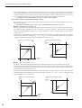
2.3.3 Frequency Measurement Counter
2.3.3 Frequency Measurement Counter
The frequency is calculated from the input pulse A and B trains and stored in the input register (Counter Value) every
high-speed scan (or low-speed scan).
The diagram below illustrates an example of the frequency measurement counter operation.
Nn-2
Nn-1
Nn
Nn+1
Nn+2
1
T
Input pulse
Time (s)
T
Frequency
f1
Counter value
f2
f3
f4
f5
f6
f7
f8
Nn-2
Nn-1
Nn
Nn+1
Nn+1
Nn+2
Nn+2
Ts
Ts = scan setting (s)
<Principle of Frequency Measurement>
The frequency is calculated using the following equation.
f=
Nn - Nn-1
T
× MULT
f : Frequency
Nn, Nn-1 : Current counter count value of input pulse of every control cycle
T : Time between input pulses (The measurement time minimum unit: 4 MHz = 0.25μs)
MULT : Frequency coeffecient (set in the fixed parameter)
The above equation is applicable when more than one pulse is input within a measurement cycle. If no pulse is
input within a measurement cycle, the frequency estimated from the previously calculated value is set as the
result (f5 in the above diagram), and the true value (f6 in the above diagram) is calculated in the following measurement cycle when pulses are input.
28
2.4 Counter Functions
2.4 Counter Functions
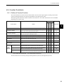
2.4.1 Outline of Counter Function
The counter functions are used to write the status and the count value in the input registers according to the counter
operation method specified by the counter fixed parameters and output register values.
The following table outlines the CNTR-01 Module counter functions. The counter functions that can be used differ
depending on the counter mode.
Frequency
Measurement
Details
Interval
Function Name
Reversible
Counter Mode*
Reference
2
PI Latch
Latches the count value at the phase-C signal of DI signal input.
9
Coincidence Output
Outputs a DO signal when the count value agrees with the preset
value, and writes the status in the status register.
9
9
9
P.35, P.36
P.41
Coincidence Interrupt
Sends an interrupt signal to the CPU of the Machine Controller when
the count value agrees with the preset value.
9
9
9
P.35, P.36
P.41
Mask of Calculation by C-Pulse
Stops counting while the phase-C pulse is being input.
9
Count Disable
Stops counting during the time specified in the output data.
9
Count Preset
Resets the count value to the preset value.
9
Electronic Gear
Converts the count value into reference units.
9
Ring Counter
Controls cyclicly the count value in the range between 0 to the set
value.
9
P.32, P.43
Zone Output
Outputs a DO signal when the count value is in the zone specified by the
upper limit and lower limit, and writes the status in the status register.
9
P.35, P.36
P.47
Speed Coincidence
Outputs a DO signal when the feedback speed is in the range specified by the
detection value and width, and writes the status in the status register.
9
P.35, P.36
P.48
Frequency Coincidence
Outputs a DO signal when the detected frequency is in the range specified by
the detection value and width, and writes the status in the status register.
Multipurpose
Outputs
P.35, P.40
P.32, P.38
9
P.35, P.38
P.35, P.36
P.39
9
P.32, P.44
9
P.35, P.36
P.48
* In the counter mode marked with 9 , the counter function can be used.
The above functions can be used by setting the fixed parameters (see P.30) and output data (see P.35).
29
2 Specifications and Functions for CNTR-01 Module
2.4.2 Setting the Counter Fixed Parameters
2.4.2 Setting the Counter Fixed Parameters
This section describes the procedure to set the counter fixed parameters.
In this manual, the fixed parameters indicate the counter fixed parameters unless otherwise specified.
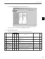
( 1 ) Open the Fix Parameter Set Tab Page
Set the fixed parameters for the counter funcions in the Fixed Parameters Tab Page of the Counter Module Definition
Window. Use the following procedure to open the Counter Module Definition Window.
1.
Double-click the Module Configuration under the Definition Folder in the File Manager Window.
The Engineering Manager will start and the Module Configuration Window will open.
2.
Point to CNTR-01 in Module Type row of the Controller section of the Module Configuration Window. Double-click the slot number of the CNTR01 in the Module Details section.
The Counter Module Definition Window will open.
30
2.4 Counter Functions
3.
Select the Fix Parameter Set Tab Page to display the page.
2
Fig 2.1 Fix Parameter Set Tab Page in the Counter Module Definition Window
Set the fixed parameters for each channel in the Fix Parameter Set Tab Page.
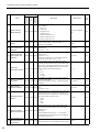
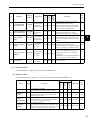
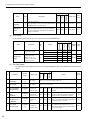
( 2 ) List of Fix Parameter Set
The following table lists the fixed parameters. Refer to the reference page for details .
Reversible
Interval
Frequency
Measurement
Counter Mode
SYNC-SCAN
Valid
Valid
Valid
Specify whether the I/O data of counter function is
updated in synchronization with High-speed scan or
Low-speed scan.
High
─
01
Channel selection
Valid
Valid
Valid
Specify whether to use or not to use the channel.
0: Not use, 1: Use
0: Not use
─
02
The First Register
Number
Valid
Valid
Valid
Specify the leading register number to be used for the
channel.
03
A/B Pulse Signal
form Selection
Valid
Valid
Valid
Select the signal form of the phase-A and -B pulses.
0: +5-V differential input, 1: 12-V collector input
0: +5-V differential
input
─
04
C-Pulse signal type
Valid
Valid
Valid
Select the signal form of the phase-C pulse.
0: +5-V differential input, 1: 12-V collector input
0: +5-V differential
input
─
05
A/B Pulse Signal
Polarity
Valid
Valid
Valid
Set the polarity of the phase-A and -B pulses.
0: Positive polarity, 1: Negative polarity
0: Positive polarity
P.38
06
C-Pulse signal
polarity selection
Valid
Valid
Valid
Set the polarity of the phase-C pulse.
0: Positive polarity, 1: Negative polarity
0: Positive polarity
─
No.
Name
Description
Default Value
Ref.
Page
─
31
2 Specifications and Functions for CNTR-01 Module
2.4.2 Setting the Counter Fixed Parameters
Frequency
Measurement
Default Value
Ref.
Page
6: Phase-A/-B pulses
(×4)
P.38
Description
07
Pulse Counting
Mode Selection
Valid Valid
Valid
Select the pulse counting method from the following
seven methods.
0: Sign (×1)
1: Sign (×2)
2: Up/Down (×1)
3: Up/Down (×2)
4: Phase-A/-B pulses (×1)
5: Phase-A/-B pulses (×2)
6: Phase-A/-B pulses (×4)
08
Counter Mode Selection
Valid Valid
Valid
Select the counter mode.
0: Reversible counter, 1: Interval counter, 2:
Frequency measurement
0: Reversible counter
mode
P.26
09
Coincidence Detection Function Use
Selection
Valid Valid
Valid
Set whether to use or not to use the coincidence detection function.
0: Not use, 1: Use
0: Not use
P.41
10
Coincidence Interrupt Function Use
Selection
Valid
Set whether to use or not to use the coincidence interrupt function.
0: Not use, 1: Use
(Valid only when the No. 09: Coincidence Interrupt
Function Use Selection is set to 1: Use.)
0: Not use
P.41
Valid Valid
Set the number of digits of the detected frequency
when the fixed parameter No.08 (Counter Mode Selection) is set to 2: Frequency Measurement. The actually
detected frequency multiplied by the value set here
will be written as the detected frequency.
0: × 1
0: ×1
1: ×10
2: ×100
3: ×1000
11
Frequency
Invalid Invalid Valid
calculation selection
12
Mask of Calculation
by C-Pulse
Set whether to prohibit or permit counting while the
pulse C is being input.
Valid Invalid Invalid
0: Enabled (prohibits counting), 1: Disabled (permits
counting)
1: Disabled*1
P.38
13
Ring-Counter
function selection
Set whether to use or not to use the ring counter funcValid Invalid Invalid tion.
0: Not use, 1: Use
0: Not use
P.43
14
15
16
32
Name
Interval
No.
Reversible
Counter Mode
Reference Unit Selection*2
Valid Valid
Number of Digits
Valid Valid
Below Decimal Point
Travel Distance per
Machine Rotation
(scale pitch)
Valid
Valid
Valid Valid Invalid
Specify the unit to be used for monitoring. When the
unit other than pulse is selected, the electronic gear
function can be used. When pulse is selected, the electronic gear function cannot be used.
0: pulse
0: pulse
1: mm
2: deg
3: inch
Set the number of degits to the right of the decimal
point for the minimum reference unit in the range
between 0 to 5.
<Example>
If the minimum reference unit is 1μm (10-3mm),
set the Reference Unit Selection to 3: mm, and Number of Decimal Places to 3
3
Set the load moving amount per load axis rotation in
10000
the range between 1 and 2147483647 (reference units).
─
P.44
─
P.44
2.4 Counter Functions
Frequency
Measurement
Reversible
Counter Mode
Name
17
Encoder Gear Ratio
Valid
Set the value m in the range between 1 and 65535 when
Valid Invalid the load axis rotates n times while the encoder axis rotates
m times.
1
P.44
18
Machine Gear Ratio
Valid
Set the value n in the range between 1 and 65535 when
Valid Invalid the load axis rotates n times while the encoder axis
rotates m times.
1
P.44
19
Maximum value of
Ring Counter
(POSMAX)
When the fixed parameter No. 13 (Ring-Counter function selection) is set to 1: Use, set the position to be
Valid Invalid Invalid
reset every turn in the range between 1 and
2147483647 (reference units).
360000
P.43
16384
(Before multiplication)
P.44
Interval
Description
20
Encoder Resolution
(Pre Quadrature)
Valid
Valid
21
Feedback speed
moving average
time constant
Valid
Set the moving average filter time constant to be used
Valid Invalid to calculate the feedback speed in the range between 0
and 32.
Valid
Set the number of input pulses per encoder rotation in
the range between 1 and 2147483647 (pulses/rev).
Default Value
Ref.
Page
No.
1
2
–
* 1. With MPE720 Ver.5.33, the default value of Mask of Calculation by C-Pulse is 0: Enabled.
* 2. When the fixed parameter No.14 (Reference Unit Selection) is set to 0: pulse, the settings of No. 16 through 19 are
disregarded.
2.4.3 Setting the I/O Data
( 1 ) Opening the I/O Data Set Tab Page
Set the I/O Data in the I/O Data Set Tab Page of the Counter Module Definition Window. (Refer to 2.4.2 Setting the
Counter Fixed Parameters on page 30 for information on how to open the Counter Module Definition Window.)
Fig 2.2 I/O Data Set Tab Page in the Counter Module Definition Window
The status to be checked and the I/O data to be specified are explained below.
33
2 Specifications and Functions for CNTR-01 Module
2.4.3 Setting the I/O Data
( 2 ) In Data Items
[ a ] Status (RUNSTS)
The status of each register bit is displayed in the Status field. “ ● ” is displayed when the bit is ON while “ ○ ” is displayed when the bit is OFF. Gray circles are displayed in offline mode.
Name
Bit No.
Meaning
Error Setting the Data
0
1 (ON): Data setting error
Fixed Parameter Error
1
1 (ON): Fixed parameter setting error
Preset Count Completed
2
1 (ON): Count value preset completed
PI Latch Completed
3
1 (ON): PI latch completed
A/B Pulse 0
4
1 (ON): Feedback pulse is ± 1 or less.
Coincidence Detection
5
1 (ON): Coincidence detection sitnal ON
A-Pulse Status Monitor
6
1 (ON): High
B-Pulse Stats Monitor
7
1 (ON): High
C-Pulse Status Display
8
1 (ON): High
Remarks
Detected in pulse units.
Fixed Parameter Write
9
1 (ON): Writing a fixed parameter
ON only during write.
Phase-A or -B Disconnect
A
Fixed to 0 (OFF)
For future use
POSMAX Preset
C
1 (ON): Completed
Multipurpose signal
D
1 (ON): Multi-purpose signal ON
Module Ready
F
1 (ON): Counter processing being executed
[ b ] In Data Details
The following items are displayed in the In data field.
The abbreviation of the register name to store the corresponding data is given in parentheses in the Data Name column.
34
Number*
00
Status
(RUNSTS)
IW
+ 00
01
Incremental Pulses
(PDV)
IL
+ 02
02
Counter Value
(PFB)
IL
+ 04
03
PI Latch Value (PINT)
IL
+ 06
04
After Convert Increment Pulse (PDVG)
05
Current Count Value
After Conversion
(PINTG)
IL
+ 08
IL
+ 0A
Range (Unit)
Frequency
Measurement
Data Name
Interval
No.
Reversible
Counter Mode
Register
Description
Ref.
Page
Bit setting
Valid Valid Valid Refer to [ a ] Status (RUNSTS).
─
−2147483648 to
Indicates the difference between the pulse
Valid Valid Valid count value at the previous scan and that at the
current scan.
─
2147483647
(pulse)
−2147483648 to
2147483647
(pulse)
−2147483648 to
2147483647
(pulse)
−2147483648 to
2147483647
(reference unit)
−2147483648 to
2147483647
(reference unit)
Valid Valid Valid Indicates the pulse count value every scan.
P.26
Indicates the current counter count value at
the moment an external signal is input.
P.40
Valid Valid Invalid
Indicates the number of incremental pulses
converted into reference units. When the
Valid Valid Valid fixed parameter No. 14 (Reference Unit Selection) is set to pulse, the converted value is the
same as the number of incremental pulses.
─
Indicates the current counter count value converted into reference units. When the fixed
Valid Valid Valid parameter No. 14 (Reference Unit Selection)
is set to pulse, the converted value is the same
as the current count value.
─
2.4 Counter Functions
Number*
06
PI Latch Value After
Converts (FREQG)
IL
+ 0C
07
Number of POSMAX
Turns (PMAXTURN)
IL
+ 0E
08
Feedback Speed
(FSPD)
IL
+ 10
09
Detected Frequency
(FREQ)
IL
+ 12
Range (Unit)
Frequency
Measurement
Data Name
Interval
No.
Reversible
Counter Mode
Register
Ref.
Page
Description
Indicates the value of PI latch data/interval
data converted into reference units.
Valid Valid Invalid When the fixed parameter No. 14 (Reference
Unit Selection) is set to pulse, the converted
value is the same as the PI latch data.
─
−2147483648 to
Indicates the number of turns up to the present
Valid Invalid Invalid when the fixed parameter No. 13 (RingCounter function selection) is set to be used.
P.43
−2147483648 to
When the electronic gear function is not used
(the fixed parameter No. 14 (Reference Unit
Valid Valid Invalid
Selection) is set to pulse), pulse/sec is used as
the unit.
P.47
Indicates the frequency detected at the
moment an external signal is input.
“m” indicates the set value of the fixed parameter No. 11 (Frequency calculation selection).
P.26
-2147483648 to
2147483647
(reference unit)
2147483647
(turn)
2147483647
(reference unit)
−2147483648 to
2147483647
Invalid Invalid Valid
(10-m Hz)
10
Average Frequency
(FRQAVE)
IL
+ 14
Indicates the average of the detected frequency values of the number of times speci2147483648
to
−
fied in the output data No. 10 (Averaging
Invalid Invalid Valid
2147483647
count setting).
(10-m Hz)
m indiates the value set in the fixed parameter
No. 11 (Frequency calculation selection).
11
System Monitor
IL
+ 1E
−2147483648 to Valid Valid Valid
For system analysis
2
─
─
2147483647
*
indicates the leading register number.
( 3 ) Out Data Items
Click the Set Button to output the settings made in the Out data field.
[ a ] Operation Mode
Set the following items for the bits 0 to 5 of the Operation Mode (RUNMOD: OW
+ 00).
Description
Frequency
Measurement
Bit No.
Interval
Name
Reversible
Counter Mode
Default Value
Ref.
Page
Count Disable
0
1: Prohibited, 0: Permitted
Specify whether to prohibit or permit counting.
Valid Valid Invalid 0: Permitted
P.38
Calculating
Preset
1
1:Reset, 0: Not reset
Specify whether to reset or not to reset the count
value to the preset value.
Valid Invalid Invalid 0: Not reset
P.39
PI Latch
Detect Demand
2
1: Latch, 0: Not latch
Specify whether to store or not to store the count
value when an external signal is input.
Valid Valid Invalid 0: Not latch
P.40
3
1: Output, 0: Not output
Specify whether to output or not to output the coinciValid Valid Valid 0: Not output
dence detection signal when the counter count value
and the coincidence detection set value match.
Coincidence
Detection
P.41
35
2 Specifications and Functions for CNTR-01 Module
2.4.3 Setting the I/O Data
Frequency
Measurement
Description
4
1: Reset, 0: Not reset
Specify whether to reset or not to reset the number of
POSMAX turns to its preset value.
Valid Invalid Invalid 0: Not reset
P.43
5
1: Detect, 0: Not detect
Specify whether to detect or not to detect the multipurpose output (zone output/speed coincidence/frequency coincidence).
Valid Invalid Valid 0: Not detect
P.47
POSMAX
Presetting
Multipurpose
output
Default Value
Ref.
Page
Bit No.
Interval
Name
Reversible
Counter Mode
[ b ] Set Function
Set the following items using the bit 0 to 7 of the Set Function (OW
+01).
PI latch detection
signal
Set the external signal to
be used for PI latch.
0 to 3
Multipurpose
output
When the Multi-purpose
Output Detection
Request is set to 1:
Detect, set the output
detection method.
4 to 7
Frquency
Measurement
Bit
No.
Interval
Description
Name
Reversible
Counter Mode
0: PI (discrete input)
Valid
Invalid
Invalid
2: Pulse C
Valid
Invalid
Invalid
0: Invalid
Valid
─
Valid
1: Zone output
Valid
Invalid
Invalid
2: Speed coincidence
Valid
Invalid
Invalid
3: Frequency coincidence Invalid
Invalid
Valid
Setting
Default
Value
Ref.
Page
0: PI
P.40
0:
Invalid
─
P.47
P.48
P.48
[ c ] Out Data Details
The abbreviation of the register name to store the corresponsing data is given in the parentheses in the Data Name
column.
36
Register
Number*
Range (Unit)
Frequency
Measurement
Data Name
Interval
No.
Reversible
Counter Mode
Details
Ref.
Page
Operation Mode
(RUNMOD)
OW
Bit settings
+ 00
Refer to [ a ] Operation Mode on page 35.
─
Set Function
OW
Bit settings
+ 01
Refer to [ b ] Set Function.
─
01
Count Presetting
Data (PRSDAT)
OL
+ 02
-2147483648 to
2147483647
(reference unit)
Set a value to which the current counter count
Valid Invalid Invalid value is reset when the Count Preset Request is
executed.
P.39
02
Agreed Detection
Value
(COINDAT)
OL
+ 04
-2147483648 to
2147483647
(reference unit)
Set the current counter count value to output the
Valid Valid Valid coincidence detection signal and output the
interrupt signal to the Machine Controller.
P.41
03
Preset Data of
POSMAX Turns
(TURNPRS)
OL
+ 06
-2147483648 to
2147483647
(turn)
Set a value to which the number of POSMAX
Valid Invalid Invalid turns is reset when the POSMAX Turn Number
Presetting Demand is executed.
P.43
04
Zone output
minimum value
OL
+ 08
-2147483648 to
2147483647
(reference unit)
Set the zone lower limit when the Multi-purpose Output Detection Request is set to 1:
Valid Invalid Invalid
Detect and the Multi-purpose Output Selection
is set to Zone Output.
P.47
2.4 Counter Functions
Frequency
Measurement
Reversible
Counter Mode
Ref.
Page
Range (Unit)
05
Zone output
maximum value
OL
+ 0A
-2147483648 to
2147483647
(reference unit)
Set the zone upper limit when the Multi-purpose Output Detection Request is set to 1:
Valid Invalid Invalid
Detect and the Multi-purpose Output Selection
is set to zone output.
P.47
06
Speed coincidence
detection setting
OL
+ 0C
-2147483648 to
2147483647
Valid Invalid Invalid
Set the detection speed when the Multi-purpose
Output Detection Request is set to 1: Detect and
the Multi-purpose Output Selection is set to
Speed Coincidence.
P.48
07
Speed coincidence
detection width
OL
+ 0E
-2147483648 to
2147483647
Set the speed detection width when the Multipurpose Output Detection Request is set to 1:
Valid Invalid Invalid
Detect and the Multi-purpose Output Selection
is set to speed coincidence.
P.48
08
Frequency
coincidence
detection setting
OL
+ 10
Set the detection frequency when the Multi-purpose Output Detection Request is set to 1:
0 to 2147483647 Invalid Invalid Valid
Detect and the Multi-purpose Output Selection
is set to Frequency Coincidence.
09
Frequency
coincidence
detection width
OL
+ 12
-2147483648 to
2147483647
10
Averaging count
setting
OW
0 to 255
+ 14
Invalid Invalid Valid
11
System Monitor
OW
-2147483648 to
2147483647
+ 1E
Valid Valid Valid For system analysis
Data Name
Interval
Register
Number*
No.
Details
Set the frequency detection width when the
Multi-purpose Output Detection Request is set
Invalid Invalid Valid
to 1: Detect and the Multi-purpose Output
Selection is set to Frequency Coincidence.
Set the number of times of frequency detection
to calculate the input data No. 10 (Average Frequency).
2
P.48
P.48
─
─
*
indicates the leading register number.
37
2 Specifications and Functions for CNTR-01 Module
2.5.1 A/B Pulses Counting Mode
2.5 Counter Function Details
This section describes the details on the fixes parameter and input/output data setting items.
The counter function is valid in the counter mode indicated with ○○
while it is not valid in the counter mode indi-
cated with ○○ .
2.5.1 A/B Pulses Counting Mode
Reversible
Interval
Frequency Measurement
The pulses A and B counting method can be selected by setting the following fixed parameters.
No.
05
07
Name
Details
Default Value
A/B Pulse Signal Polarity
Set the polarity of phase-A and -B pulse signals:
0: Positive logic, 1: Negative logic
0: Positive logic
Pulse Counting Mode
Selection
Select the pulse counting method:
0: Sign (× 1)
1: Sign (× 2)
2: Up/Down (× 1)
3: Up/Down (× 2)
4: Pulses A/B (× 1)
5: Pulses A/B (× 2)
6: Pulses A/B (× 4)
6: A/B (× 4)
For details on the pulse counting methods, refer to 2.2 Pulse Counting Methods on page 24.
2.5.2 Mask of Calculation by C-Pulse
Reversible
Interval
Frequency Measurement
This function is used to stop counting while the pulse C is being input. This function is enabled by setting the fixed
parameter No. 12 (Mask of Calculation by C-Pulse) to 0: Enabled. However, this function is invalid while the PI Latch
Detection Demand using the pulse C is ON.
While the pulse counting is being stopped, counting the following values is stopped: Number of Incremental Pulses
(PDV; IL
+2), Counter Value (PFB; IL
+4), After Convert Increment Pulse (PDVG; IL
+8),
and Current Count Value After Conversion (PFBG: IL
+A)
An operation example of the Mask of Calculation by C-Pulse is given in 2.3.1 Reversible Counter on page 26.
2.5.3 Count Disable
Reversible
Interval
Frequency Measurement
This function stops counting while the bit 0 (Count Disable) of the Operation Mode (OW
+00) of the Setting
Output Data is ON.
This function can be used independently from the Mask of Calculation by C-Pulse.
While the pulse counting is being stopped, counting the following values is stopped: Number of Incremental Pulses
(PDV; IL
+2), Counter Value (PFB; IL
+4), After Convert Increment Pulse (PDVG; IL
+8),
and Current Count Value After Conversion (PFBG: IL
+A)
An operation example of the Count Prohibit function is given in 2.3.1 Reversible Counter on page 26.
38
2.5 Counter Function Details
2.5.4 Calculating Preset
Reversible
Interval
Frequency Measurement
This function forcibly resets the counter count value to the value specificied in the Count Preset Data (OL
+2).
The counter value is reset to the preset value when the the signal of the bit 2 (Calculating Preset) of the Operation
Mode OW
+00 of the Setting Output Data is input (detection at the signal rising edge). When the value is reset
to the preset value, the bit 2 (Preset Count Completed) of the Status (IW
+00) of the In Data turns ON.
Calculating Preset
Preset Count
Completed
An operation example of the Calculating Preset function is given in 2.3.1 Reversible Counter on page 26.
When using the ring counter function, set the calculating preset data to a value between 0 and the value “POSMAX1”.
2
The following diagram shows the count preset completion timing of the CNTR-01 Module.
Count Preset Request: ON
Scan cycle Ts
Calculating Preset
(Count Preset Request)
(OW Bit 1)
Count Preset Completed: ON
Preset Count Completed
(IW Bit 2)
Count Preset
m2
Counter count register
value
m4
m1
Current Count Value After
Converts
(IL + 00A)
m3
m2̉
m1
m2
m3
m4
Data that reflects
count preset value
39
2 Specifications and Functions for CNTR-01 Module
2.5.5 PI Latch
INFO
The following diagram shows the count preset completion timing of the LIO-01 Module.
Count Preset Request: ON
Scan cycle Ts
Calculating Preset
(Count Preset Request)
(OW Bit 1)
Count Preset Completed: ON
Preset Count Completed
(IW Bit 2)
Count Preset
m2
Counter count register
value
m4
m1
Current Count Value After
Converts
(IL + 00A)
m3
m2̉
m1
m2̉
m3
m4
Data that reflects
count preset value
2.5.5 PI Latch
Reversible
Interval
Frequency Measurement
This function stores (latches) the counter count value at the moment an external signal is input (at the rising edge
detecting point) in the register (IL
+06: PINT) as the PI latch data.
Either a discrete input (PI input) or pulse C can be selected for the external signal to be used.
The following graph shows the PI latch process: Execution of PI latch detection request, detection of the external input
signal rising edge, storage of the PI latch data in the register.
When the electronic gear function is enabled (when the fixed parameter No. 14 (Reference Unit Selection) is set to
other than pulse), the latch data converted into reference units is written in the input register PI Latch Value After Converts/Interval Data After Conversion.
㧔㧗㧕
Signal rising edge detected
PI Latch Data
Current counter
0
count value
㧔㧙㧕
Hardware latch
Time (s)
PI Latch Detection
Request
External input signal
(discrete (PI) input or
pulse C)
Discrete (PI): ON for 30Ǵs min.*
Pulse C: ON for 125 ns min.
PI Latch Completed
signal
PI Latch Register
display
PINT (PI Latch Data)
* At least 600 μs must elapse before accepting the ON signal after the signal turns OFF from ON.
40
2.5 Counter Function Details
2.5.6 Coincidence Output/Coincidence Interrupt
Reversible
Interval
Frequency Measurement
This function outputs the coincidence output signal and outputs an interrupt signal to the Machine Controller when the
count value becomes the value predefined in the output register (Agreed Detection Value: OL
+4).
The Coincidence Detection (Operation Mode of Out Data) is enabled when the fixed parameter No. 9 (Coincidence
Detection Function Use Selection) is set to 1: Use. And, the Coincidence Interrupt Request is enabled when the fixed
parameter No. 10 (Coincidence Interrupt Function Use Selection) is set to 1: Use.
The following graph shows the Coincidence Output/Coincidence Interrupt process: Execution of the coincidence
detection request, detection of the coincidence point, and reception of the interrupt.
㧔㧗㧕
Coincidence point
2
Agreed Detection Value
㧔COINDAT㧕
Counter value
0
㧔㧙㧕
Time (s)
Coincidence point
detection value
COINT
Coincidence
Detection Request
Coincidence
output signal
Interrupt Request
signal
T0*
T1*
Interrupt received
* T0: Maximum time from when the Machine Controller receives an interrupt request signal until it starts interrupt
processing (70 to 120 μs)
TI: Time from when an interrupt request signal is received until the DWG.I (interrupt drawing) execution starts
Normal program execution
:
Approx. 90 to 170 μs
Direct I/O command execution
:
Approx. 90 to (1460+40+N) μs (N = No. of direct I/O words (Max. 8))
Use the Coincidence Detection Signal of the Status to monitor the coincidence detection signal output.
Precautions When Using the Ring Counter
㧔㧕
Current
counter
value
after
conversion
Maximum value of ring counter
㧔POSMAX㧕
Agreed Detection Value
㧔COINDAT㧕
0
41
2 Specifications and Functions for CNTR-01 Module
2.5.6 Coincidence Output/Coincidence Interrupt
When the fixed parameter No. 13 (Ring-Counter function selection) is set to 1: Use, the coincidence detection value exists every
cycle as shown in the diagram above. For the coincidence detection processing when the ring counter function is enabled, the
coincidence detection set value closest to the current counter count value after conversion is obtained and set every scan. Therefore, if a pulse that exceeds one cycle is input within 1 scan, the coincidence detection may not be executed.
For details on the ring counter function, refer to 2.5.7 Ring Counter on page 43.
Precautions When Using the Electronic Gear Function
Errors in the result of unit conversion from/to reference unit from/to pulse may cause the following differences in the coincidence detection operation.
For details on the electronic gear function, refer to 2.5.9 Electronic Gear Function on page 44.
● When 1 reference unit = n pulses (n > 1)
The value p0 converted from the coincidence detection set value m (reference unit) into pulses is the coincidence detected value.
The counter value whose value after conversion is equal to m is p0 or more but less than p1. When the pulse to increment the
count (in the direction indicated with the arrow A) is input, the CNTR-01 executes coincidence detection at the timing the
counter value = m.
When the pulse to decrement the count (in the direction indicated with the arrow B) is input, the current counter value after conversion is equal to m when the counter value = p1 − 1 (p1 + 1 if p0 < 0). However, the CNTR-01 Module does not execute the
coincidence detection at this timing, but executes at the timing the counter value = p0.
When p0 is a positive value
When p0 is a negative value
pulse
m 1
Reference
units
B
m
m 1
p1
p0
p0
A
A
p0
p0
p1
B
m 1
m
m 1
Reference
units
pulse
● When 1 pulse = n reference units (n > 1)
The value p converted from the agreed detection value m0 (reference units) into pulses is the coincidence detected value.
The current counter value after conversion converted from the counter value p is m0 or more but less than m1. When the pulse
to increment the count (in the direction indicated with the arrow A) is input, the CNTR-01 Module executes coincidence detection at the timing the current count value = m0.
When the pulse to decrement the count (in the direction indicated with the arrow B) is input, the CNTR-01 Module executes
coincidence detection at the timing the current counter value after conversion = m1 − 1 (m1 + 1 if m0 < 0)before the current
counter value after conversion becomes m0.
When m0 is a positive value
When m0 is a negative value
pulse
m1
Reference
units
B
m0
p+1
p
p
p-1
A
p-1
A
p
B
m0
42
m1
Reference
units
p
p+1
pulse
2.5 Counter Function Details
2.5.7 Ring Counter
Reversible
Interval
Frequency Measurement
The Ring Counter function cyclicly controls the counter count value to be written in the input register within the range
between 0 and the maximum ring counter value (POSMAX). Set the maximum ring counter value in the fixed parameter No. 19 (Maximum value of Ring Counter).
When the fixed parameter No. 13 (Ring-Counter function selection) is set to 1: Use, the value of the input register
Number of POSMAX Turns (PMAXTURN: IL
+E) increments by 1 (for forward rotation) or decrements by 1
(for reverse rotation) every time the count value exceeds the ring counter reset position.
This function can be used for the machine configuration to be reset cyclicly without using a special application program.
㧔㧕
Maximum value of
ring counter
(POSMAX㧕
Current counter value
after conversion
2
0
2.5.8 Number of POSMAX Turns Preset
Reversible
Interval
Frequency Measurement
This function forcibly resets the value of Number of POSMAX Turns (PMAXTURN:IL
+E) to the value specified in Preset Data of POSMAX Turns of the Operation Mode (TURNPRS: OL
+6) of the Out Data.
When the value is reset to the preset value, the bit C (POSMAX Turn Number Presetting Completed) of the Status
(IW
+00) of the In Data turns ON.
POSMAX Presetting
POSMAX Preset
43
2 Specifications and Functions for CNTR-01 Module
2.5.9 Electronic Gear Function
2.5.9 Electronic Gear Function
Reversible
Interval
Frequency Measurement
The Electronic Gear function can be used when other than pulse is set to the fixed parameter No. 14 (Reference Unit
Selection).
( 1 ) Outline
The Electronic Gear function is used to set per pulse input to the CNTR-01 Module to any reference unit value.
To calculate the number of required pulses for the system shown below, the operations when using the electronic gear
and when not using the electronic gear differ as explained below.
Workpiece
No. of encoder pulses: 8192
Ball screw pitch: 6 mm
<When the Electronic Gear is Not Used>
<When the Electronic Gear is Used>
If 13653 pulses are input, the number of revolutions is
13653 ÷ 8192 = 1.666 (revolutions)
1 revolution moves the workpiece 6mm, therefore the travel
amount by 1666 revolutions is
6 (mm/revolution) × 1.666 (revolutions) = 9.999 (mm)
Therefore, the workpiece moves for 9999 mm by inputting
13653 pulses. This equation must be calculated at the host
controller.
Mechanical conditions such as the moving amount per
machine rotation, encoder gear ratio, anc machine gear ratio
are predefined and the minimum reference unit is set to 1
μm.
To move the workpiece 10 mm,
10 (mm) ÷ 1 (μm) = 10000 reference units
Input 10000 reference units.
( 2 ) Settings
Use the following procedure to make the settings.
1.
Confirm the machine specifications.
Elements relating to the Electronic Gear
• Gear ratio
• Ball screw pitch
• Pully diameter, etc.
Ball screw pitch
Gear ratio
2.
Confirm the number of encoder pulses displayed in Counter Value, and set this value to the fixed
parameter No. 20 (Encoder Resolution (Pre Quadrature)).
3.
Set the reference unit (the smallest unit for the reference data to move the load) according to the settings of the fixed parameter No. 14 (Reference Unit Selection) and No. 15 (Number of Digits Below
Decimal Point).
Reference to move a table in
units of 0.001 mm
Reference unit 0.001mm
Consider the machine specifications and positioning
precision when setting the reference unit.
When reference unit is 1μm, inputting 50,000 reference pulses moves the workpiece by 50000 × 1μm = 50 mm.
44
2.5 Counter Function Details
4.
Find the load travel distance per load axis rotation using the reference unit, and set to the fixed
parameter No. 16 (Travel Distance per Machine Rotation).
Load travel distance per load axis rotation reference unit
Travel distance per machine rotation axis
=
(reference unit)
Reference unit
<Calculation Example>
For a ball screw pitch of 5 mm and a reference unit is 0.001 mm
5 - = 5000
-----------0.001
(Reference unit)
Ball screw
Load axis
Round table
Belt + pully
Load axis
P
πD
2
D
P: Pitch
One
rotation
5.
P
Reference unit
D: Pully diameter
Load axis
One
rotation
360
Reference unit
One
rotation
πD
Reference unit
Set the Encoder Gear Ratio and the Machine Gear Ratio in the fixed parameters No. 17 and No. 18.
When the encoder axis has rotated m times and the mechanical configuration allows the load axis to rotate n
times, set the following values.
No.17: Encoder Gear Ratio = m (rotations)
No.18: Machine Gear Raio = n (rotations) (Setting range: 1 to 65,535 (rotations))
<Setting Example>
• For the configuration shown in the diagram
4 rotations
4回転
7 rotations
7回転
Load負荷軸
axis nn回転
rotations
Encoder axis
エンコーダ軸
m rotations
m回転
9 rotations
9回転
3 rotations
3回転
Gear ratio = n / m = (3 / 7) × (4 / 9) = 4 / 21
Therefore, set the following values.
No.17: Encoder Gear Ratio = 4 (rotations)
No.18: Machine Gear Ratio = 21 (rotations)
45
2 Specifications and Functions for CNTR-01 Module
2.5.9 Electronic Gear Function
( 3 ) Setting Examples
The following are setting examples for each kind of load mechnical configuration.
[ a ] Setting Example for Ball Screw
m
7 rotations
Encoder
n
5 rotations
Ball screw pitch
P = 6 mm/rotation
In the above machine system, if the reference unit = 0.001 mm, the setting of each parameter will be as follows.
• Moving Amount per Machine Rotation = 6mm / 0.001mm = 6000
• No. 17: Encoder Gear Ratio = 7 (rotations)
• No. 18: Machine Gear Ratio = 5 (rotations)
[ b ] Setting Example for Rotating Load
m
30 rotations
Encoder
n
10 rotations
Rotating load
360 / rotation
In the above machine system, if the reference unit = 0.1°, the setting of each parameter will be as follows.
• Moving Amount per Machine Roration = 360° / 0.1°= 3600
• No. 17: Encoder Gear Ratio = 3 (rotations)
• No. 18: Machine Gear Ratio = 1 (rotation)
46
2.5 Counter Function Details
2.5.10 Multipurpose Output Function
The function is used to output the multi-purpose output signal externally when the specified output condition is satisfied and the Multipurpose Output is executed.
The output condition can be selected by setting the output register Multi-purpose Output Selection according to the
selected counter mode.
This section describes each output condition.
( 1 ) Zone Output
Reversible
Interval
Frequency Measurement
The multi-purpose output signal is output at the rising edge of Multi-purpose Detection Request signal when the output
register Multipurpose Output is set to 1: Zone Output and the counter value is in the range between the zone output
minimum value and the zone output maximum value.
As the counter value is detected by software processing, there will be a delay of maximum 500μs .
Operation examples of the Zone Output is illustrated below.
2
■ When Zone Output Maximum Value < Zone Output Minimum Value
2147483647㧔MAX㧕
㧔㧕
Maximum value of ring counter
(POSMAX)
Zone output maximum value
Counter
0
count
register
Zone output minimum value
㧔㧕
2147483648㧔MIN㧕
Multi-purpose
output signal
■ When Zone Output Maximum Value > Zone Output Minimum Value
2147483647㧔MAX㧕
㧔㧕
Maximum value of ring counter
(POSMAX)
Zone output minimum value
Counter
count register 0
Zone output maximum value
㧔㧕
2147483648㧔MIN㧕
Multi-purpose
output signal
47
2 Specifications and Functions for CNTR-01 Module
2.5.10 Multipurpose Output Function
■ When Zone Output Maximum Value = Zone Output Minimum Value
The Multi-purpose Output signal is output when the counter value and the zone output minimum value (= the zone output upper limit) match.
Operation When Using the Ring Counter
The zone output operation will be as shown below when the fixed parameter No. 13 (Ring-Counter function selection) is set to
1: Use.
● When Zone Output Minimum Value < Zone Output Maximum Value
㧔㧕
Maximum value of ring counter
(POSMAX)
Zone output maximum value
Current
counter
value
after
conversion
Zone output minimum value
0
Multi-purpose
output signal
● When Zone Output Minimum Value > Zone Output Maximum Value
㧔㧕
Maximum value of ring counter
(POSMAX)
Zone output minimum value
Current
counter
value
after
conversion
Zone output maximum value
0
Multi-purpose
output signal
For information on the ring counter function, refer to 2.5.7 Ring Counter on page 43.
( 2 ) Speed Coincidence Output
Reversible
Interval
Frequency Measurement
The multi-purpose output signal is output at the rising edge of Multipurpose Output signal when the output register
Multipurpose Output is set to 2: Speed Coincidence and the feedback speed calculated from the difference between the
counter values in two control cycles is within the range Speed Coincidence Detection Width whose center point is the
set value of the output register Speed Coincidence Detection Setting.
The software processing for detecting the counter count value cause a delay for 500 μs maximum.
( 3 ) Frequency Coincidence Output
Reversible
Interval
Frequency Measurement
The multi-purpose output signal is output at the rising edge of Multipurpose Output signal when the output register
Multipurpose Output is set to 3: Frequency Coincidence and the frequency measured by the frequency measurement
counter is within the range Speed Coincidence Detection Width whose center point is the set value of the output register Speed Coincidence Detection Setting.
The software processing for detecting the counter count value cause a delay for 500μs maximum.
48
3
CNTR-01 Module Connections
This chapter explains the detailed specifications and functions, connection methods, and settings of
the CNTR-01 Module.
3
3.1 CNTR-01 Module Connections - - - - - - - - - - - - - - - - - - - - - - - - - - - - - - - 50
3.1.1 Specifications on Cable and Connector - - - - - - - - - - - - - - - - - - - - - - - - - - - - - - - - - - -50
3.1.2 Connector Pin Arrangement - - - - - - - - - - - - - - - - - - - - - - - - - - - - - - - - - - - - - - - - - - - 51
3.2 CNTR-01 Connection Example - - - - - - - - - - - - - - - - - - - - - - - - - - - - - - - 52
49
3 CNTR-01 Module Connections
3.1 CNTR-01 Module Connections
3.1.1 Specifications on Cable and Connector
( 1 ) Connector Specifications
Used to connect for the multi-purpose output signals or pulse input signals.
Connector
Name
Connector
External I/O
Connector
Connector Model
No. of
Pins
40
CN1
Module
Cable
10240-52A3PL
Manufacturer
・Connector
10140-6000EL
・Shell
10340-3210-006
(One-touch- lock type)
Sumitomo
3M
( 2 ) Connector Models and External Appearance of Standard Cable
Cable
Length
JEPMC-W2063-A5-E
0.5 m
Apprearance (JEPMC-W2063--E)
L
150
JEPMC-W2063-01-E
1m
JEPMC-W2063-03-E
3m
JEPMC-W2063E-㧖㧖
Laminate tape
3M
10340
Cable for CNTR-01
Module
Model
Shielded wire
( 3 ) Standard Cable Wiring
The following table shows thewiring for the JEPMC-W2063--E standard cable loose wire.
Terminal No.
21
40
50
1
20
Dot Mark
Wire Color
Dot Mark
Terminal No.
1
-
Orange
Continuous- - -
21
2
-
Gray
Continuous- - -
22
3
-
White
Continuous- - -
23
4
-
Yellow
Continuous- - -
24
5
-
Pink
Continuous- - -
25
6
--
Orange
-
26
7
--
Gray
-
27
8
--
White
-
28
9
--
Yellow
-
29
10
--
Pink
-
30
11
---
Orange
--
31
12
---
Gray
--
32
13
---
White
--
33
14
---
Yellow
--
34
15
---
Pink
--
35
16
----
Orange
---
36
17
----
Gray
---
37
18
----
White
---
38
19
----
Yellow
---
39
20
----
Pink
---
Shielded wire
40
Shell
3.1 CNTR-01 Module Connections
3.1.2 Connector Pin Arrangement
The following table shows the connector (CN1) of the pin arrangement and the terminal layout for the CNTR-01 module.
( 1 ) Pin Arrangement and Terminal Layout
21
1
2
22
Pin Arrangement at Connection Side
1
2
+5PB1
4
SG
6
+5PB2
3
5
7
+5PA1
39
40
26
-5PB2
+5PC2
12VA1
12VB1
11
19
SG
+5PA2
13
12VA2
15
12/24VC2
12VB2
16
17
18
OUT1
20
PIL1
19
30
12PB1
32
24PC1
12/24VC1
12
20
24
21
-5PA1
23
-5PC1
25
-5PA2
27
-5PC2
29
12PA1
31
12PC1
33
12PA2
35
12PC2
37
COIN2
39
24V
28
9
14
-5PB1
+5PC1
8
10
22
34
12PB2
36
24PC2
38
OUT2
40
PIL2
COIN1
0V (24V)
3
( 2 ) Terminal Specifications
No.
1
Signal
Name
+5PA1
I/O
Function
No.
I
5V differential A1 pulse input(+) 21
Signal
Name
-5PA1
I/O
Function
I
5V differential A1 pulse input (−)
2
+5PB1
I
5V differential B1 pulse input(+) 22
-5PB1
I
5V differential B1 pulse input (−)
3
+5PC1
I
5V differential C1 pulse input(+) 23
-5PC1
I
5V differential C1 pulse input (−)
4
SG
─
Ground (for pulse input)
24
SG
─
Ground (for pulse input)
5
+5PA2
I
5V differential A2 pulse input(+) 25
-5PA2
I
5V differential A2 pulse input (−)
6
+5PB2
I
5V differential B2 pulse input(+) 26
-5PB2
I
5V differential B2 pulse input (−)
7
+5PC2
I
5V differential C2 pulse input(+) 27
-5PC2
I
5V differential C2 pulse input (−)
8
─
─
28
─
9
12VA1
P
Power supply 12VA1 input
29
12PA1
I
12VA1 pulse input
10
12VB1
P
Power supply 12VB1 input
30
12PB1
I
12VB1 pulse input
11
12/24VC1
P
Power supply 12/24VC1 input
31
12PC1
I
12VC1 pulse input
12
─
─
32
24PC1
I
24VC1 pulse input
13
12VA2
P
Power supply 12VA2 input
33
12PA2
I
12VA2 pulse input
14
12VB2
P
Power supply 12VB2 input
34
12PB2
I
12VB2 pulse input
15
12/24VC2
P
Power supply 12/24VC2 input
35
12PC2
I
12VC2 pulse input
16
─
─
17
COIN1
O
O
─
Latch input 1
18
OUT1
19
0V (24V)
20
PIL1
I
─
36
24PC2
I
24VC2 pulse input
37
COIN2
O
Coincidence detection output 2
Multi-purpose output 1
38
OUT2
O
Multi-purpose output 2
Ground (24V) 8
39
24V
P
24V power supply input
40
PIL2
I
Latch input 2
Coincidence detection output 1
P: Power supply input, I: Input signal, O: Open-collector output
51
3 CNTR-01 Module Connections
3.2 CNTR-01 Connection Example
The following diagram shows the connection example of the CNTR-01.
CNTR-01
CH1 pulse 㧭
CH1 pulse B
Fixed
parameter
setting
Pulse generator
5V-line driver
output
1
+5PA1
330ǡ
21
-5PA1
+5PB1
330ǡ
2
22
3
+5PC1
23
4
-5PC1
SG
9
12VA1
29
12PA1
10
12VB1
30
12PB1
11
12/24VC1
31
12PC1
32
24PC1
330ǡ
P
P
-5PB1
∗
P
1.5Kǡ
1.5Kǡ
680ǡ
1.5Kǡ
CH1 pulse C
Fixed
parameter
setting
1.5Kǡ
680ǡ
1.5Kǡ
1.5Kǡ
680ǡ
1Kǡ
CH2 pulse 㧭
CH2 pulse B
Fixed
parameter
setting
5
+5PA2
330ǡ
25
-5PA2
330ǡ
6
26
+5PB2
7
+5PC2
27
24
-5PC2
SG
13
12VA2
33
12PA2
14
12VB2
34
12PB2
330ǡ
∗
-5PB2
∗
680ǡ
1.5Kǡ
1.5Kǡ
CH2 pulse C
Fixed
parameter
setting
680ǡ
1.5Kǡ
15
1.5Kǡ
680ǡ
1.5Kǡ
35
12PC2
36
24PC2
∗
Junction terminal block
1.5Kǡ
Pulse generator
12V-open collector
output
12V
1Kǡ
CH1 Coincidence
detection output
39
24V
17
COIN1
37
COIN2
0V
㧸
CH2 Coincidence
detection output
㧸
DC power
supply
+
DC24V
-
CH1 Multi-purpose
output
18
OUT1
38
OUT2
19
0V(24V)
5.6Kǡ
20
PIL1
5.6Kǡ
40
PIL2
DC power
supply
+
DC12V
-
㧸
CH2 Multi-purpose
output
㧸
1.0A
CH1 Latch input
CH2 Latch input
Connector shell
Standard cable
JEPMC-W2063-غغ-E
* If not connecting the phase C with modules, set the fixed parameter No.12 (Counting Mask Using Pulse C) to Disabled.
52
INDEX
INDEX
Error Setting the Data
external I/O connector
- - - - - - - - - - - - - - - - - - - - - - - - - 34
- - - - - - - - - - - - - - - - - - - - - - - - - 50
F
A
A/B Pulse 0 - - - - - - - - - - - - A/B Pulse Signal from Selection - A/B Pulse Signal Polarity - - - - - A/B pulses counting mode - - - - After Convert Increment Pulse - - Agreed Detection Value - - - - - - appearance and external dimensions
applicable machine controllers - - A-Pulse Status Monitor - - - - - - Average Frequency - - - - - - - - Averaging count setting - - - - - - -
- - - - - - - - - - - - - - - - - 34
- - - - - - - - - - - - - - - - - 31
- - - - - - - - - - - - - - - - - 31
- - - - - - - - - - - - - - - - - 38
- - - - - - - - - - - - - - - - - 34
- - - - - - - - - - - - - - - - - 36
- - - - - - - - - - - - - - - - - 20
- - - - - - - - - - - - - - - - - 14
- - - - - - - - - - - - - - - - - 34
- - - - - - - - - - - - - - - - - 35
- - - - - - - - - - - - - - - - - 37
B
B-Pulse Stats Monitor
- - - - - - - - - - - - - - - - - - - - - - - - - 34
C
cable wiring - - - - - - - - - - - - - - - - - - Calculating Preset - - - - - - - - - - - - - - - calculating preset - - - - - - - - - - - - - - - Channel selection - - - - - - - - - - - - - - - Coincidence Detection - - - - - - - - - - - - Coincidence Detection Function Use Selection
Coincidence Interrupt - - - - - - - - - - - - - coincidence interrupt - - - - - - - - - - - - - Coincidence Interrupt Function Use Selection Coincidence Output - - - - - - - - - - - - - - coincidence output - - - - - - - - - - - - - - COINDAT - - - - - - - - - - - - - - - - - - - connection example - - - - - - - - - - - - - - connector - - - - - - - - - - - - - - - - - - - connector pin arrangement - - - - - - - - - - Count Disable - - - - - - - - - - - - - - - - - count disable - - - - - - - - - - - - - - - - - - Count Preset - - - - - - - - - - - - - - - - - - count preset - - - - - - - - - - - - - - - - - - Count Presetting Data - - - - - - - - - - - - - counter function details - - - - - - - - - - - - counter functions - - - - - - - - - - - - - - - Counter Mode Selection - - - - - - - - - - - counter modes - - - - - - - - - - - - - - - - - Counter Value - - - - - - - - - - - - - - - - - counter value - - - - - - - - - - - - - - - - - C-Pulse signal polarity selection - - - - - - - C-Pulse signal type - - - - - - - - - - - - - - C-Pulse Status Display - - - - - - - - - - - - Current Count Value After Conversion - - - - -
- - - - - - - - - - - - - - - - - - - - - - - - - - 35
E
Electronic Gear - - - electronic gear function
Encoder Gear Ratio - Encoder Resolution - -
- - - - - - - - - - - - - - - - - - - - - - - - 29
- - - - - - - - - - - - - - - - - - - - - - - - 44
- - - - - - - - - - - - - - - - - - - - - - - - 33
- - - - - - - - - - - - - - - - - - - - - - - - 33
- - - - - - - - - - - 35
- - - - - - - - - - - 33
- - - - - - - - - - - 34
- - - - - - - - - - - 34
- - - - - - - - - - - 35
- - - - - - - - - - - 35
- - - - - - - - - - - 32
- - - - - - - - - - - 29
- - - - - - - - - - - 37
- - - - - - - - - - - 37
- - - - - - - - - - - 48
- - - - - - - - - - - 28
- - - - - - - - - - - 35
- - - - - - - - - - - 35
- - - - - - - - - - - 20
G
general specifications
- - - - - - - - - - - 50
- - - - - - - - - - - 35
- - - - - - - - - - - 39
- - - - - - - - - - - 31
- - - - - - - - 34, 35
- - - - - - - - - - - 32
- - - - - - - - - - - 29
- - - - - - - - - - - 41
- - - - - - - - - - - 32
- - - - - - - - - - - 29
- - - - - - - - - - - 41
- - - - - - - - - - - 36
- - - - - - - - - - - 52
- - - - - - - - - - - 50
- - - - - - - - - - - 51
- - - - - - - - 29, 35
- - - - - - - - 27, 38
- - - - - - - - - - - 29
- - - - - - - - - - - 26
- - - - - - - - - - - 36
- - - - - - - - - - - 38
- - - - - - - - - - - 29
- - - - - - - - - - - 32
- - - - - - - - - - - 26
- - - - - - - - - - - 34
- - - - - - - - 26, 27
- - - - - - - - - - - 31
- - - - - - - - - - - 31
- - - - - - - - - - - 34
- - - - - - - - - - - 34
D
Detected Frequency
Feedback Speed - - - - - - - - - - - - - - - - Feedback speed moving average time constant
Fixed Parameter Error - - - - - - - - - - - - - Fixed Parameter Write - - - - - - - - - - - - FREQ - - - - - - - - - - - - - - - - - - - - - FREQG - - - - - - - - - - - - - - - - - - - - Frequency calculation selection - - - - - - - Frequency Coincidence - - - - - - - - - - - - Frequency coincidence detection setting - - - Frequency coincidence detection width - - - frequency coincidence output - - - - - - - - - frequency measurement counter - - - - - - - FRQAVE - - - - - - - - - - - - - - - - - - - - FSPD - - - - - - - - - - - - - - - - - - - - - - functions - - - - - - - - - - - - - - - - - - - - -
- - - - - - - - - - - - - - - - - - - - - - - - - 21
H
hardware specifications
- - - - - - - - - - - - - - - - - - - - - - - - 21
I
in data details - - - - - - in data items - - - - - - - Incremental Pulses - - - installing optional modules
interval counter - - - - - interval data - - - - - - - Inverval Latch - - - - - - -
- - - - - - - - - - - - - - - - - - - - - - 34
- - - - - - - - - - - - - - - - - - - - - - 34
- - - - - - - - - - - - - - - - - - - - - - 34
- - - - - - - - - - - - - - - - - - - - - - 16
- - - - - - - - - - - - - - - - - - - - - - 27
- - - - - - - - - - - - - - - - - - - - - - 27
- - - - - - - - - - - - - - - - - - - - - - 27
J
JEPMC-W2063--E
- - - - - - - - - - - - - - - - - - - - - - - - 50
LED indicators - - - list of fix parameter set
- - - - - - - - - - - - - - - - - - - - - - - - 22
- - - - - - - - - - - - - - - - - - - - - - - - 31
L
M
Machine Gear Ratio - - - - - - - - - - - - - - - - - - - - Mask of Calculation by C-Pulse - - - - - - - - - - - - - mask of calculation by C-pulse - - - - - - - - - - - - - - maximum value of ring counter - - - - - - - - - - - - - minimum width of pulse counting - - - - - - - - - - - - Module Ready - - - - - - - - - - - - - - - - - - - - - - - mounting option modules - - - - - - - - - - - - - - - - - mounting/removing option modules on machine controller
Multipurpose output - - - - - - - - - - - - - - - - - - - - multipurpose output function - - - - - - - - - - - - - - - Multipurpose Outputs - - - - - - - - - - - - - - - - - - - Multipurpose signal - - - - - - - - - - - - - - - - - - - - -
- - - - - 33
- - 29, 32
- - - - - 38
- - - - - 33
- - - - - 23
- - - - - 34
- - - - - 14
- - - - - 14
- - - - - 36
- - - - - 47
- - - - - 29
- - - - - 34
N
Number of Digits Below Decimal Point
Number of POSMAX Turns - - - - - number of POSMAX turns preset - - -
- - - - - - - - - - - - - - - 32
- - - - - - - - - - - - - - - 35
- - - - - - - - - - - - - - - 43
53
INDEX
O
open the fix parameter set tab page - Operation Mode - - - - - - - - - - - operation mode - - - - - - - - - - - - operation when using the ring counter
out data details - - - - - - - - - - - - out data items - - - - - - - - - - - - - outline of counter function - - - - - - overflow - - - - - - - - - - - - - - - -
-----------------------------------------------------------------------------------------------------------------
30
36
35
48
36
35
29
27
P
PDV - - - - - - - - - - - - - - - - - - - - - - - - - - - - - - PDVG - - - - - - - - - - - - - - - - - - - - - - - - - - - - - PFB - - - - - - - - - - - - - - - - - - - - - - - - - - - - - - Phase-A or -B Disconnect - - - - - - - - - - - - - - - - - - PI Latch - - - - - - - - - - - - - - - - - - - - - - - - - - - - PI latch - - - - - - - - - - - - - - - - - - - - - - - - - - - - PI Latch Completed - - - - - - - - - - - - - - - - - - - - - PI Latch Detect Demand - - - - - - - - - - - - - - - - - - - PI latch detection signal - - - - - - - - - - - - - - - - - - - PI Latch Value - - - - - - - - - - - - - - - - - - - - - - - - PI Latch Value After Converts - - - - - - - - - - - - - - - - pin arrangement - - - - - - - - - - - - - - - - - - - - - - - PINT - - - - - - - - - - - - - - - - - - - - - - - - - - - - - PINTG - - - - - - - - - - - - - - - - - - - - - - - - - - - - PMAXTURN - - - - - - - - - - - - - - - - - - - - - - - - - POSMAX - - - - - - - - - - - - - - - - - - - - - - - - - - - POSMAX Preset - - - - - - - - - - - - - - - - - - - - - - - POSMAX Presetting - - - - - - - - - - - - - - - - - - - - - Pre Quadrature - - - - - - - - - - - - - - - - - - - - - - - - precautions when using the electronic gear function - - - - precautions when using the ring counter - - - - - - - - - - Preset Count Completed - - - - - - - - - - - - - - - - - - - Preset Data of POSMAX Turns - - - - - - - - - - - - - - - PRSDAT - - - - - - - - - - - - - - - - - - - - - - - - - - - pulse A/B method - - - - - - - - - - - - - - - - - - - - - - pulse counting methods - - - - - - - - - - - - - - - - - - - Pulse Counting Mode Selection - - - - - - - - - - - - - - - -
-------------------------------------------------------
34
34
34
34
29
40
34
35
36
34
35
51
34
34
35
33
34
36
33
42
41
34
36
36
25
24
32
-------------------------------------------------------------------------------------------------------------------------------------------------------------------
32
15
17
26
29
43
32
36
34
R
Reference Unit Selection - - removing optional cover - - - removing optional modules - reversible counter - - - - - - Ring Counter - - - - - - - - - ring counter - - - - - - - - - - Ring-Counter function selection
RUNMOD - - - - - - - - - - RUNSTS - - - - - - - - - - - -
S
scale pitch - - - - - - - - - - - - - Set Function - - - - - - - - - - - - set function - - - - - - - - - - - - - setting the counter fixed parameters sign method - - - - - - - - - - - - - specifications - - - - - - - - - - - - specifications on cable and connector
Speed Coincidence - - - - - - - - - Speed coincidence detection setting -
54
----------------------------------------------------------------------------------------------------------------------------------------
32
36
36
30
24
21
50
29
37
Speed coincidence detection width
speed coincidence output - - - - standard cable - - - - - - - - - - standard cable wiring - - - - - - Status - - - - - - - - - - - - - - - SYNC-SCAN - - - - - - - - - - System Monitor - - - - - - - - - -
- - - - - - - - - - - - - - - - - 37
- - - - - - - - - - - - - - - - - 48
- - - - - - - - - - - - - - - - - 50
- - - - - - - - - - - - - - - - - 50
- - - - - - - - - - - - - - - - - 34
- - - - - - - - - - - - - - - - - 31
- - - - - - - - - - - - - - - 35, 37
T
The First Register Number - - - - - - Travel Distance per Machine Rotation
TURNPRS - - - - - - - - - - - - - - -
- - - - - - - - - - - - - - - 31
- - - - - - - - - - - - - - - 32
- - - - - - - - - - - - - - - 36
U
underflow - - - - - UP/DOWN method
- - - - - - - - - - - - - - - - - - - - - - - - - 27
- - - - - - - - - - - - - - - - - - - - - - - - - 24
Z
Zone Output - - - - - - - - zone output - - - - - - - - - Zone output maximum value
Zone output minimum value -
-----------------------------------------------------------------------------
29
47
37
36
Revision History
The revision dates and numbers of the revised manuals are given on the bottom of the back cover.
MANUAL NO.ޓSIEP C880700 27A
Published in Japan
February 2008 05-9 0 -1
Date of
publication
Date of
Publication
May 2010
Rev.
No.
0
WEB
Rev.
No.
5
WEB revision number
Revision number
Date of original
publication
Section
Revised Contents
2.4.2
Revision: Counter mode of feedback speed moving average time constant (no.21)
2.4.3 (3) [b]
Revision: Bit no.
November 2009
4
3.1.1 (3)
Revision: Dot mark’s description, “Sequence number- - -” to “Continuous- - -.”
September 2009
3
Preface
Addition: Warranty
Back cover
Revision: Address
Revision: The diagrams of down count (reverse) of pulse A/B method (×1)
May 2008
2
2.2.3
February 2008
1
All chapters
Slightly revised
2.1.3 (4)
Addition: CNTR-01 Module status indication
2.5.4
Addition: Count preset completion timing
Back cover
–
First edition
September 2005
–
–
Revision: Address
Machine Controller MP2000 Series
Counter Module
CNTR-01 USER'S MANUAL
IRUMA BUSINESS CENTER (SOLUTION CENTER)
480, Kamifujisawa, Iruma, Saitama 358-8555, Japan
Phone 81-4-2962-5696 Fax 81-4-2962-6138
YASKAWA ELECTRIC AMERICA, INC.
2121 Norman Drive South, Waukegan, IL 60085, U.S.A.
Phone (800) YASKAWA (800-927-5292) or 1-847-887-7000 Fax 1-847-887-7370
YASKAWA ELETRICO DO BRASIL LTDA.
Avenida Fagundes Filho, 620 Sao Paulo-SP CEP 04304-000, Brazil
Phone 55-11-3585-1100 Fax 55-11-5581-8795
YASKAWA ELECTRIC EUROPE GmbH
Hauptstraβe 185, 65760 Eschborn, Germany
Phone 49-6196-569-300 Fax 49-6196-569-398
YASKAWA ELECTRIC UK LTD.
1 Hunt Hill Orchardton Woods Cumbernauld, G68 9LF, United Kingdom
Phone 44-1236-735000 Fax 44-1236-458182
YASKAWA ELECTRIC KOREA CORPORATION
7F, Doore Bldg. 24, Yeoido-dong, Youngdungpo-Ku, Seoul 150-877, Korea
Phone 82-2-784-7844 Fax 82-2-784-8495
YASKAWA ELECTRIC (SINGAPORE) PTE. LTD.
151 Lorong Chuan, #04-02A, New Tech Park 556741, Singapore
Phone 65-6282-3003 Fax 65-6289-3003
YASKAWA ELECTRIC (SHANGHAI) CO., LTD.
No.18 Xizang Zhong Road. Room 1702-1707, Harbour Ring Plaza Shanghai 200001, China
Phone 86-21-5385-2200 Fax 86-21-5385-3299
YASKAWA ELECTRIC (SHANGHAI) CO., LTD. BEIJING OFFICE
Room 1011A, Tower W3 Oriental Plaza, No.1 East Chang An Ave.,
Dong Cheng District, Beijing 100738, China
Phone 86-10-8518-4086 Fax 86-10-8518-4082
YASKAWA ELECTRIC TAIWAN CORPORATION
9F, 16, Nanking E. Rd., Sec. 3, Taipei, Taiwan
Phone 886-2-2502-5003 Fax 886-2-2505-1280
YASKAWA ELECTRIC CORPORATION
YASKAWA
In the event that the end user of this product is to be the military and said product is to be
employed in any weapons systems or the manufacture thereof, the export will fall under
the relevant regulations as stipulated in the Foreign Exchange and Foreign Trade
Regulations. Therefore, be sure to follow all procedures and submit all relevant
documentation according to any and all rules, regulations and laws that may apply.
Specifications are subject to change without notice
for ongoing product modifications and improvements.
© 2005-2010 YASKAWA ELECTRIC CORPORATION. All rights reserved.
MANUAL NO. SIEP C880700 27A
Published in Japan May 2010 05-9 0 -5
09-8-2