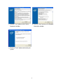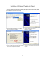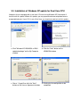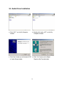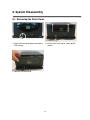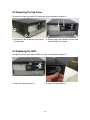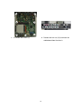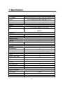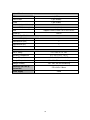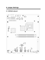
1
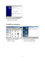
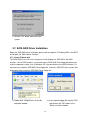
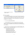
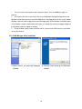
User Manual April 2010 Revision 1.1 POSEO 5200 Hardware System Copyright 2008 ~2010 All Rights Reserved Manual Version 1.1 The information contained in this document is subject to change without notice. We make no warranty of any kind with regard to this material, including, but not limited to, the implied warranties of merchantability and fitness for a particular purpose. We shall not be liable for errors contained herein or for incidental or consequential damages in connection with the furnishing, performance, or use of this material. This document contains proprietary information that is protected by copyright. All rights are reserved. No part of this document may be photocopied, reproduced or translated to another language without the prior written consent of the manufacturer. TRADEMARK Intel®, Pentium® and MMX are registered trademarks of Intel® Corporation. Microsoft® and Windows® are registered trademarks of Microsoft Corporation. 2 Safety IMPORTANT SAFETY INSTRUCTIONS 1. To disconnect the machine from the electrial power supply, turn off the power switch and remove the power cord plug from the wall socket. The wall socket must be easily accessible and in close proximity to the machine. 2. Read these instructions carefully. Save these instructions for future reference. 3. Follow all warnings and instructions marked on the product. 4. Do not use this product near water. 5. Do not place this product on an unstable cart,stand,or table.The product may fall, causing serious damage to the product. 6. Slots and openings in the cabinet and the back or bottom are provided for ventilation;to ensure reliable operation of the product and to protect it from overheating. These openings must not be blocked or covered.The openings should never be blocked by placing the product on a bed, sofa, rug, or other similar surface.This product should never be placed near or over a radiator or heat register,or in a built-in installation unless proper ventilation is provided. 7. This product should be operated from the type of power indicated on the marking label.If you are not sure of the type of power available, consult your dealer or local power company. 8. Do not allow anything to rest on the power cord. Do not locate this product where persons will walk on the cord. 9. Never push objects of any kind into this product through cabinet slots as they may touch dangerous voltage points or short out parts that could result in a fire or electric shock. Never spill liquid of any kind on the product. CE MARK This device complies with the requirements of the EEC directive 2004/108/EC with regard to “Electromagnetic compatibility” and 2006/95/EC “Low Voltage Directive”. FCC This device complies with part 15 of the FCC rules. Operation is subject to the following two conditions: (1) This device may not cause harmful interference. (2) This device must accept any interference received, including interference that may cause undesired operation. 3 CAUTION ON LITHIUM BATTERIES There is a danger of explosion if the battery is replaced incorrectly. Replace only with the same or equivalent type recommended by the manufacturer. Discard used batteries according to the manufacturer’s instructions. LEGISLATION AND WEEE SYMBOL 2002/96/EC Waste Electrical and Electronic Equipment Directive on the treatment, collection, recycling and disposal of electric and electronic devices and their components. The crossed dustbin symbol on the device means that it should not be disposed of with other household wastes at the end of its working life. Instead, the device should be taken to the waste collection centers for activation of the treatment, collection, recycling and disposal procedure. To prevent possible harm to the environment or human health from uncontrolled waste disposal, please separate this from other types of wastes and recycle it responsibly to promote the sustainable reuse of material resources. Household users should contact either the retailer where they purchased this product, or their local government office, for details of where and how they can take this item for environmentally safe recycling. Business users should contact their supplier and check the terms and conditions of the purchase contract. This product should not be mixed with other commercial wastes for disposal. 4 Revision History Revision Number Description Revision Date 1.0 Initial release 2008 August 1.1 Updated specifications Updated motherboard drawing Added Appendix B: Dimensional Drawings & Moved BIOS Error Codes to Appendix C 2010 April 5 Table of Contents 1. Packing List.................................................................................................................... 7 2. System View .................................................................................................................. 8 2.1 Front View............................................................................................................. 8 2.2 Rear View ............................................................................................................. 9 3. Driver Installation ......................................................................................................... 10 3.1 Driver List............................................................................................................ 10 3.2 Chipset Driver Installation ................................................................................... 10 3.3. Installation of Windows XP update for Dual Core CPU...................................... 13 3.4. VGA Driver Installation....................................................................................... 14 3.5. Audio Driver Installation ..................................................................................... 16 3.6 LAN Driver Installation ........................................................................................ 17 3.7. SATA RAID Driver Installation ............................................................................ 18 4. Peripherals Installation................................................................................................. 22 4.1. Cash Drawer Installation.................................................................................... 22 5. Hardware Status Display.............................................................................................. 24 6. System Disassembly.................................................................................................... 27 6.1. Removing the Front Cover................................................................................. 27 6.2 Removing the Top Cover .................................................................................... 28 6.3 Replacing the HDD ............................................................................................. 28 6.4. Replacing the DVD-ROM................................................................................... 29 6.5. Replacing the Power Supply.............................................................................. 30 6.6. Replacing the I/O & PCI Extension Module ....................................................... 31 6.7. Replacing the Memory ....................................................................................... 32 6.8. Replacing the Motherboard................................................................................ 32 7. Specification................................................................................................................. 34 8. Jumper Settings ........................................................................................................... 36 8.1. B99 Motherboard ............................................................................................... 36 8.2. Connectors ........................................................................................................ 37 8.3. Jumper Settings ................................................................................................. 38 9. RAID BIOS Settings ..................................................................................................... 41 Appendix A: PCI Card Dimensions................................................................................ 47 Appendix B: Dimensional Drawings .............................................................................. 48 Appendix C: BIOS Error Codes ..................................................................................... 49 6 1. Packing List Take the system unit out of the carton. Remove the unit from the carton by holding it by the foam inserts. The following contents should be found in the carton: a. Power Cable b. Driver CD 7 2. System View 2.1 Front View Hardware Status Display 2 x USB Key Lock Power Button HDD 8 Power Connectivity Module 2.2 Rear View AC Power COM2 & 4 Power Power Power USB USB USB 24V 12V 5V USB DVI Line Out DC Output 24V LPT COM 3 & 5 USB CD 1 P/S 2 Keyboard VGA COM1 DC Output 12V LAN Note: The maximum current that can be drawn from each COM port is 500 mA. DC output 24 V Pin Assignment 9 3. Driver Installation 3.1 Driver List Folder/File File Description <CD>:\Poseo5200.htm POSEO 5200 Driver List <CD>:\Common/Intel/Chipset/i9xx Chipset Driver <CD>:\Common/INTEL/Utility/WindowsXP_update/KB92 Windows XP update (Chipset) 1411(Chipset) <CD>:\Common/INTEL/Utility/WindowsXP_update/KB89 Windows XP update 6256(Dual%20Core%20CPU) (Dual Core CPU) <CD>:\COMMON/INTEL/VGA/i94x VGA Driver <CD>:\Common\INTEL\Raid\ICH7R\Windows\Driver SATA RAID Driver <CD>:\Common\INTEL\Raid\ICH7R\Windows\raid_tools RAID Manager Utility <CD>:\Common\AC97_Codec\Realtek\ALC202A Audio Driver <CD>:\Common\Lan_driver\Realtek_PCI\ LAN Driver -The following procedures are for Windows XP, other platforms are similar. 3.2 Chipset Driver Installation a. Double click "infinst_autol_v8.0.1.1002” on the My Computer window. window. b. Click the "Next" button on the Welcome window. 10 c. Click the "Yes" button on the License d. Click the ”Next” button on the Readme Agreement window. Information window. e. Click the “Finish” button and restart your system. 11 Installation of Windows XP update for Chipset * You must install this update after installing the Chipset driver. Without this update, your USB ports may not work correctly. a. Click "WindowsXP-KB921411-x86-ENU” on the My Computer window. b. Click the "Next" button on the KB921411 window. c. Chose “I Agree” then click the “Next” button d. Click the “Finish”button and restart your on the License Agreement window system. 12 3.3. Installation of Windows XP update for Dual Core CPU Computers that are equipped with a dual core CPU and running Windows XP Service pack 2 should install this update. Without this update, you may experience decreased performance or unexpected behavior. If your CPU is not a Dual Core, you should not need to install this update. a. Click "WindowsXP-KB896256-v4-ENU updated package” on the My Computer window. b. Click the "Next" button on the KB896256 window. c. Chose “ I Agree”then click the "Next" button on the License Agreement window. d. Waiting for the configuration to be completed. 13 e. Click the “Finish” button and restart your system 3.4. VGA Driver Installation a. Double click "win2k_xp1425" on the My Computer window. b. Click the "Next" button on the Welcome window. 14 c. Click the “Next” button on the Welcome Window d. Click the “Next” button on the Readme Information Window e. Click the ”Yes”button on the License Agreement window. f. Click the ”Finish”button and restart your system. 15 3.5. Audio Driver Installation a. Click “A3.71” on the My Computer window. b. Double click “wdm_a371” on the My Computer window. c. Click “Next” button on the Realtek AC’97 d. Click “Yes” button on the Digital d. Audio Setup window. Signature Not Found window. 16 e. Click “Finish” button on the Realtek AC’97 Audio Setup window. 3.6 LAN Driver Installation a. Double click ”Setup” on the My Computer window. b. Click the "Finish" button on the Maintenance complete window. 17 c. Click the ”OK” button and restart your system. 3.7. SATA RAID Driver Installation Before the SATA RAID driver installation, please refer to chapter 9.5 ”Enabling RAID in the BIOS” and chapter 9.6 “RAID Volume Creation”. 3.7.1. Create F6 driver disk The SATA RAID Driver is for users who plan to install Windows on SATA HDDs with RAID functions. To use RAID functions, you need to make a SATA RAID Driver floppy disk before you install the operation system, such as Windows XP. If you do not plan to use RAID functions, it is not necessary to make a SATA RAID Driver floppy disk. Connect a USB-FDD to the system, then follow below steps to make a SATA RAID Driver floppy disk. a. Double click “F6flpy32.exe” on the My computer window. b. Insert a blank floppy disk into the FDD, and click on the "OK" button in the "Batch assistant" window. 18 c. Click the “Yes” button on the “Confirm operation” window d. Wait for the driver disk to be written. 3.7.2. F6 driver installation 1. Press the F6 key when prompted in the status line with the Press F6 if you need to install a third party SCSI or RAID driver message. This message appears at the beginning of Windows XP setup (during text-mode phase). Note: Nothing will happen immediately after pressing F6. Setup will temporarily continue loading drivers. You will then be prompted with a screen asking you to load support for mass storage device(s). 2. Press the S key to Specify Additional Device. 3. You will be prompted to Please insert the disk labeled Manufacturer-supplied hardware support disk into Drive A: When prompted, insert the floppy disk containing the following files: IAAHCI.INF, IAAHCI.CAT, IASTOR.INF, IASTOR.CAT, IASTOR.SYS, and TXTSETUP.OEM and press the Enter key. 4. After pressing Enter, you should be presented with a list of available SCSI Adapters. Select your controller from the list. The up and down arrow keys can be used to scroll through the list as all controllers may not be visible. The list may include: o Intel® 82801ER SATA RAID Controller o Intel® 82801FR SATA RAID Controller o Intel® 82801GR/GH SATA RAID Controller o Intel® 82801GHM SATA RAID Controller o Intel® 631xESB/632xESB SATA RAID Controller o Intel® 82801R/DO/DH SATA RAID Controller 19 1 The next screen should confirm your selected controller. Press the Enter key again to continue. 2 At this point, you have successfully F6'ed in the Intel® Matrix Storage Manager driver and Windows setup should continue. Leave the floppy disk in the floppy drive until the system reboots. Windows setup will need to copy the files from the floppy again to the Windows installation folders. Once Windows setup has copied these files again, you should then remove the floppy diskette so that Windows setup can reboot as needed. 3 During Windows setup, create a partition and file system on the RAID volume as you would on any physical disk. 3.7.3. RAID Manager Utility installation a. Select “iata621_cd” on the My Computer Window b. Click the “Next” button on the Welcome window 20 c. Click the “Next” button on the Warning window d. Click the “Yes”button on the License Agreement window e. Click the “Next” button on the Readme window f. Select “Yes, I want to restart my computer now” and click the “Finish” button to complete the installation 21 4. Peripherals Installation 4.1. Cash Drawer Installation You can install a cash drawer through the Cash Drawer port. Please verify the pin assignment before installation. 4.1.1. Cash Drawer Pin Assignment Pin Signal 1 GND 2 DOUT bit0 3 DIN bit0 4 12V/24V 5 DOUT bit1 6 GND 4.1.2. Cash Drawer Controller Register The Cash Drawer Controller use one I/O address to control the Cash Drawer. Register Location: 48Ch Attribute: Size: Read / Write 8 bits Bit 7: Reserved Bit 6: Cash Drawer “DIN bit0” pin input status. = 1: the Cash Drawer closed or no Cash Drawer = 0: the Cash Drawer is open 22 Bit 5: Reserved Bit 4: Reserved Bit 3: Cash Drawer “DOUT bit1” pin output control. = 1: Opening the Cash Drawer = 0: Allow close the Cash Drawer Bit 2: Cash Drawer “DOUT bit0” pin output control. = 1: Opening the Cash Drawer = 0: Allow close the Cash Drawer Bit 1: Reserved Bit 0: Reserved Note: Please follow the Cash Drawer control signal design to control the Cash Drawer. 4.1.3. Cash Drawer Control Command Example Use Debug.EXE program under DOS or Windows98 Command Cash Drawer O 48C 01 Opening O 48C 00 Allow to close Set the I/O address 48Ch bit2 =1 for opening Cash Drawer by “DOUT bit0” pin control. Set the I/O address 48Ch bit0 = 0 for allow close Cash Drawer. Command Cash Drawer I 48C Check status The I/O address 48Ch bit6 =1 mean the Cash Drawer is opened or not exist. The I/O address 48Ch bit6 =0 mean the Cash Drawer is closed. 23 5. Hardware Status Display 5.1. Introduction The Hardware Status Display in the front panel of the POSEO 5200 gives information about the working of the main portions of the system hardware. In case of malfunction, it shows which portion of the hardware has an abnormal status: - Power: CPU, 3.3V, 5V, 12V - Fan: CPU and System fan - Temperature: CPU and System temperature. As soon as you connect the power cable, the Hardware Status Display becomes active. You can follow the progress of the booting process, and if the system hangs, the Display will show a BIOS Error code which can help with the debugging. 5.2. Function Description 5.2.1 System Power is off (Standby power) Temperature HDD: no access is off Fans are off LAN: no access DC Power is off 24 5.2.2 System Power is on (Normal status) Blinking "ON" Temperature means HDD access "ON" (not blinking) means LAN access Fan is normal DC power is normal 5.2.3 System Power is on (Abormal status) If the system hangs during the boot sequence, the Hardware Status Display will show a BIOS Error Code, as shown below. BIOS Error Code Note: For a list of BIOS Error Codes, please refer to Appendix B. 25 5.3. Function Table System Action Display Shows Remarks - CPU and System Temperature (°C) System Off - CPU and System Fan are off (standby - DC Power is off power) - HDD access is off Monitor hardware status in standby power mode - LAN access is off Power On - CPU and System Temperature (°C) The Hardware Status Display will show - CPU and Fan normal/abnormal an Error Code if either o following - DC Power status normal/abnormal conditions are true: (CPU, 3.3V, 5V, 12V) - 5V power is abnormal - HDD & LAN access ON/OFF - The system can not boor normally Normal / Abnormal Thresholds • Temperature abnormal above 80°C • Fan abnormal under 1000 rpm • CPU Voltage abnormal under 0.6V • +12V Voltage abnormal under 0.675V • +5V Voltage abnormal under 0.8V • +3.3V Voltage abnormal under 1.4V 26 6. System Disassembly 6.1. Removing the Front Cover a. Open the front cover door and unlock it with the key. b. Lift the front cover up as shown by the arrows c. Remove the front cover 27 6.2 Removing the Top Cover To remove the top cover, please first follow the steps described in chapter 6.1. a. Remove the two screws on each side of b. Slide the top cover towards the front and the top cover remove it from the system. 6.3 Replacing the HDD To replace the front cover, please follow the steps as described in chapter 6.1. a. Loosen the thumb screw (1). b. Lower the locking bar (1). 28 c. Pull on the blue tab to remove the HDD. d. Repeat for the second HDD. 6.4. Replacing the DVD-ROM To replace the front cover, please follow the steps as described in chapter 6.1 a. Loosen the thumb screw (1) b. Pull the DVD-ROM holder out c. Disconnect the cables (2) to remove the DVD-ROM 29 6.5. Replacing the Power Supply To replace the power supply, please follow the steps as described in chapters 6.1 and 6.2 If you have a DVD-ROM, disconnect the cables as shown in chapter 6.4, item c. a. Remove the screws (3). b. Slide the HDD module forward to release it from the chassis c. Put the HDD module to the side as d. Disconnect the power cables (2) to shown. Slide the power supply to the side remove the power supply. as shown. e. Remove the screws (3) to separate the power supply from the holder. 30 6.6. Replacing the I/O & PCI Extension Module To replace the I/O and PCI extension module, please follow the steps as described in chapter 6.1 and 6.2 a. Remove the extension module by gently b. Disconnect the cables (2) and remove the pulling it upwards taking care not to screws (2, one on each side) to remove damage the connector. the I/O module from the holder. c. Disconnect the cables (2) and remove the screws (2) to release the PCI riser card from the holder. 31 6.7. Replacing the Memory To replace the memory, please follow the steps as described in chapter 6.1, 6.2 , 6.6(a), 6.5(a+c). a. Use your finger to push the DIMM slot b. Remove the memory module from the slot. ejector clips into the down position. 6.8. Replacing the Motherboard To replace the motherboard, please first follow the steps as described in chapters 6.1, 6.2, 6.5(a~d) and 6.6(a) a. Disconnect the HDD power cable and the b. Disconnect all the cables from the SATA cable from the HDD docking board. motherboard: Disconnect the Hardware Status Display - 20 pin power cable cable. - 40 pin IDE cable + DVD-ROM power cable - HDD SATA and power cables - 2 x fan cable - Hardware Status Display cable - Line Out and DC24V cables - VGA cable 32 c. c. Remove the screws (7) d. Remove the hex nuts (16) to release the motherboard from the chassis 33 7. Specification Mainboard CPU Support Chipset B99 LGA775 Pentium Dual Core 1.8GHz, 1MB cache, 800 MHz FSB INTEL 945G FSB 533 / 800 / 1066 MHZ / ICH7R System Memory Up to 4GB DDR ll RAM, 2 RAM-DIMM slots Graphic Memory Shared memory up to 224 MB Storage HDD 1 x 3.5" SATA, option: 1 x 3.5” SATA ODD 1 x PATA Slim CD-ROM / CD-RW / DVD-ROM Drive Bay (optional) Expansion PCI Slot 2 slots supported from PCI riser card USB 1 ( USB7 ) External I/O Ports Front I/O USB 2 ( USB1~2 ) Power Button 1 Rear I/O PS/2 Keyboard 1 USB Serial_RS232 4 ( USB3~ 6 ) 5 (COM1 , COM2, COM3, COM4, COM5) Parallel 1 LAN (10 / 100 / 1000 ) 1 VGA 1 ( DB15 ) DVI 1 Line- out 1 Cash Drawer Port 1 DC 24V output 1 DC 12V output 1 (for OLC 8.4 VESA power) Control / Indicators Power Button 1 (Front) LED_HDD/Power 2 Hardware Status Display 1 34 Internal Header USB 1 ( USB8 ) Power Button 1 ( pin header) COM6 1 (pin header) Peripherals ( special feature) Second HDD (hot swap) RAID (optional) Supports RAID 0, RAID 1 for 2 SATA HDDs System ID Built-in Connectivity Module Powered USB (12V) 2 Powered USB (24V) 1 Powered USB (5V) 1 USB 4 Environment EMC & Safety FCC Class A, CE, LVD Operating Temperature 5°C~ 35°C (41°F ~95°F) Storage Temperature -10°C~ 60°C (14°F ~140°F) Storage Temperature 10% - 90% RH non condensing Storage Humidity 10% - 90% RH non condensing Dimension (W x D x H) 270 x 345 x 120mm System Box 230W Power Supply 35 8. Jumper Settings 8.1. B99 Motherboard 36 8.2. Connectors Connectors Function CN4 COM6 Connector CN5 Connectors Function CN16 HDD Action LED Connector Speaker & MIC Connector CN17 LAN Action LED Connector CN6 CD-in & Line-in Connector CN18 CN7 USB8 CN19 LVDS (DVI) CN9 Power Connector (+5V/+12V) FAN_CPU3 CPU Fan Connector CN10 Power Connector (+5V/+12V) FAN_SYS3 System Fan Connector CN11 Hardware Reset Connector IDE3 Primary IDE Connector CN12 Power Connector (+5V/+12V) PWR3 +24V Power Output CN13 Power Connector (+5V/+12V) PWR5 +12V Connector CN15 Power LED Connector 37 Hardware Status Display connector 8.3. Jumper Settings 1. COM1 Power Setting ◎Factory Default Setting Pin 1 9 Function JP4 (SHORT) DCD# ◎1-2 +5V 3-4 +12V 5-6 RI# ◎7-8 +5V 9-10 +12V 11-12 Function JP8 (SHORT) DCD# ◎1-2 +5V 3-4 +12V 5-6 RI# ◎7-8 +5V 9-10 +12V 11-12 Function JP6 (SHORT) DCD# ◎1-2 +5V 3-4 +12V 5-6 RI# ◎7-8 +5V 9-10 +12V 11-12 Function JP5 (SHORT) DCD# ◎1-2 +5V 3-4 +12V 5-6 RI# ◎7-8 +5V 9-10 +12V 11-12 2. COM 2 Power Setting Pin 1 9 3. COM 3 Power Setting Pin 1 9 4. COM 4 Power Setting Pin 1 9 38 5. COM 5 Power Setting Pin 1 9 Function JP3 (SHORT) DCD# ◎1-2 +5V 3-4 +12V 5-6 RI# ◎7-8 +5V 9-10 +12V 11-12 6. 2ND Display Power Setting Function JP11 (SHORT) +12V 1-2 NC ◎1 7. CMOS Operation Mode Setting Function JP13 (SHORT) COMS Normal ◎N/C COMS Reset 1-2 8. Power Mode Setting Function JP14 (SHORT) ATX Power ◎N/C AT Power 1-2 9. Cash Drawer Power Setting Voltage JP7 (SHORT) +12V 1-2 + 24V ◎3-4 10. Hardware Status Display Function JP15 (SHORT) Disable ◎1-2 3-4 Enable 5-6 7-8 39 8.4. Connector and Pin Definitions CN5: Speaker & MIC Connector Pin 1 AMP_ORL Pin 2 GND Pin 3 GND Pin 4 AMP_ORR Pin 5 GND Pin 6 MIC1 CN6: CD-IN Connector Pin 1 CDIN_L Pin 2 CDIN_REF Pin 3 CDIN_R Pin 4 CDIN_REF Pin 5 GND Pin 6 LINE_IN_L Pin 7 LINE_IN_R Pin 8 GND CN7: USB8 Pin 1 +5V_USB1 Pin 2 USB20_R_P1 Pin 3 USB20_R_P1+ Pin 4 GND CN9/10/12/13: Power Connector (+5V/+12V) Pin 1 +12V Pin 2 GND Pin 3 GND Pin 4 +5V CN11: Hardware Reset Connector Pin 1 GND Pin 2 ALL_SYS_PWRGD PWR5: +12V Power Connector Pin 1 GND Pin 2 GND Pin 3 +12V_ATX Pin 4 +12V_ATX 40 9. RAID BIOS Settings 9.1. BIOS Setup Utility The BIOS setup defines how the system is configured. You need to run this program the first time you configure this product. You may need to run it again if you change the configuration. You need to connect a PC keyboard to the keyboard connector to run the BIOS setup utility. 9.2. Starting the BIOS Setup 1. Turn on or reboot this product. 2. Press the DEL key immediately after the product is turned on, or press the DEL key when the following message is displayed during POST (the Power on Self-Test). Press DEL to enter SETUP. 3. The main menu of the BIOS setup is displayed. 4. If the supervisor password is set, you must enter it here. If, after making and saving system changes with the Setup utility, you find that this product no longer boots, start the BIOS setup and execute the following. 9.3. When a Problem Occurs Load Optimized Defaults 9.4. BIOS Main Menu When the BIOS Main Menu is displayed, the following items can be selected. Use the arrow keys to select items and the Enter key to accept and enter the sub-menu. Note: The BIOS menu below is from B99 RAID BIOS version B990V10.BIN. If you have a different BIOS version, the contents of the menu may differ slightly. 41 Standard CMOS Features Use this menu for basic system configuration. Advanced BIOS Features Use this menu to set the Advanced Features available on the system. Advanced Chipset Features Use this menu to change the values in the chipset registers and optimize the system’s performance. Integrated Peripherals Use this menu to specify your settings for integrated peripherals. Power Management setup Use this menu to specify your settings for power management. PnP/PCI Configurations This entry appears if your system supports Plug and Play and PCI Configuration. PC health status Displays CPU, System Temperature, Fan Speed, and System Voltages Value. Load Optimized Defaults 42 Use this menu to load the BIOS default values, i.e., factory settings for optimal performance system operations. While Award has designed the custom BIOS to maximize performance, the factory has the option to change these defaults to meet their needs Set Supervisor Password Enables you to change, set, or disable the supervisor or user password Set Password Change, set, or disable the password. It allows you to limit access to the system and to the setup, or just to the setup. Save & exit setup Save CMOS value changes to CMOS and exits setup. Exit without saving Ignores all CMOS value changes and exits setup. 43 9.5. Enabling RAID in the BIOS Enter the BIOS Setup program by pressing the DEL key. Select Integrated Peripherals, and then press “Enter” Select OnChip IDE Device, and then press “Enter” 44 Select SATA Mode, and then press “Enter” Select RAID, and then press “Enter” Press the F10 key to save the BIOS settings and exit the BIOS Setup program. 9.6. RAID Volume Creation 1 When the Intel® Matrix Storage Manager option ROM status screen appears during POST, press the Ctrl and i keys at the same time to enter the Intel Matrix Storage Manager option ROM user interface. 2 Select Option 1: Create RAID Volume and press the Enter key. 3 Use the up or down array keys to select the RAID level and press the Enter key. 4 Unless you have selected RAID 1, use the up or down arrow keys to select the strip size and 45 press the Enter key. 5 Press the Enter key to select the physical disks. 6 Select the appropriate number of hard drives by using the up or down arrow keys to scroll through the list of hard drives and pressing the Space key to select the drive. When finished, press the Enter key. 7 Select the volume size and press the Enter key. 8 Press the Enter key to create the volume. At the prompt, press the Y key to confirm volume creation. 9 Select Option 4: Exit and press the Enter key. Press the Y key to confirm exit. 46 Appendix A: PCI Card Dimensions Maximum dimension of the PCI add-on card: Component Side: 130mm x 90.26mm ( D x W ) (Picture 1) 47 Appendix B: Dimensional Drawings 48 Appendix C: BIOS Error Codes POST (hex) CFh Description Test CMOS R/W functionality. Early chipset initialization: -Disable shadow RAM C0h C1h -Disable L2 cache (socket 7 or below) -Program basic chipset registers Detect memory -Auto-detection of DRAM size, type and ECC. -Auto-detection of L2 cache (socket 7 or below) C3h Expand compressed BIOS code to DRAM C5h Call chipset hook to copy BIOS back to E000 & F000 shadow RAM. 0h1 Expand the Xgroup codes locating in physical address 1000:0 02h Reserved 03h Initial Superio_Early_Init switch. 04h Reserved 05h 1. Blank out screen 2. Clear CMOS error flag 06h Reserved 07h 1. Clear 8042 interface 2. Initialize 8042 self-test 1. 08h Test special keyboard controller for Winbond 977 series Super I/O chips. 2. Enable keyboard interface. 09h Reserved 0Ah 1. Disable PS/2 mouse interface (optional). 2. Auto detect ports for keyboard & mouse followed by a port & interface swap (optional). 3. Reset keyboard for Winbond 977 series Super I/O chips. 0Bh ~ 0Dh Reserved 0Eh Test F000h segment shadow to see whether it is R/W-able or not. If test fails, keep beeping the speaker. 0Fh Reserved 10h Auto detect flash type to load appropriate flash R/W codes into the 49 POST (hex) Description run time area in F000 for ESCD & DMI support. 11h Reserved 12h Use walking 1’s algorithm to check out interface in CMOS circuitry. Also set real-time clock power status, and then check for override. 13h Reserved 14h Program chipset default values into chipset. Chipset default values are MODBINable by OEM customers. 15h Reserved 16h Initial Early_Init_Onboard_Generator switch. 17h Reserved 18h Detect CPU information including brand, SMI type (Cyrix or Intel) and CPU level (586 or 686). 19h ~ 1Ah Reserved 1Bh Initial interrupts vector table. If no special specified, all H/W interrupts are directed to SPURIOUS_INT_HDLR & S/W interrupts to SPURIOUS_soft_HDLR. 1Ch Reserved 1Dh Initial EARLY_PM_INIT switch. 1Eh Reserved 1Fh Load keyboard matrix (notebook platform) 20h Reserved 21h HPM initialization (notebook platform) 22h Reserved 23h 1. Check validity of RTC value: e.g. a value of 5Ah is an invalid value for RTC minute. 2. Load CMOS settings into BIOS stack. If CMOS checksum fails, use default value instead. 3. Prepare BIOS resource map for PCI & PnP use. If ESCD is valid, take into consideration of the ESCD’s legacy information. 4. Onboard clock generator initialization. Disable respective clock resource to empty PCI & DIMM slots. 5. Early PCI initialization: -Enumerate PCI bus number -Assign memory & I/O resource -Search for a valid VGA device & VGA BIOS, and put it into C000:0. 50 POST (hex) Description 24h ~ 26h Reserved 27h Initialize INT 09 buffer 28h Reserved 1. Program CPU internal MTRR (P6 & PII) for 0-640K memory address. 2. Initialize the APIC for Pentium class CPU. 29h 3. Program early chipset according to CMOS setup. Example: onboard IDE controller. 4. Measure CPU speed. 5. Invoke video BIOS. 2Ah ~ 2Ch Reserved 1. Initialize multi-language 2Dh 2. Put information on screen display, including Award title, CPU type, CPU speed …. 2Eh ~ 32h Reserved 33h Reset keyboard except Winbond 977 series Super I/O chips. 34h ~ 3Bh Reserved 3Ch Test 8254 3Dh Reserved 3Eh Test 8259 interrupt mask bits for channel 1. 3Fh Reserved 40h Test 8259 interrupt mask bits for channel 2. 41h ~ 42h Reserved 43h Test 8259 functionality. 44h ~ 46h Reserved 47h Initialize EISA slot 48h Reserved 49h 1. Calculate total memory by testing the last double word of each 64K page. 2. Program write allocation for AMD K5 CPU. 4Ah ~ 4Dh Reserved 4Eh 1. Program MTRR of M1 CPU 2. Initialize L2 cache for P6 class CPU & program CPU with proper cacheable range. 3. Initialize the APIC for P6 class CPU. 4. On MP platform, adjust the cacheable range to smaller one in case the cacheable ranges between each CPU are not identical. 4Fh Reserved 50h Initialize USB 51 POST (hex) Description 51h Reserved 52h Test all memory (clear all extended memory to 0) 53h ~54h Reserved 55h Display number of processors (multi-processor platform) 56h Reserved 1. Display PnP logo 57h 2. Early ISA PnP initialization -Assign CSN to every ISA PnP device. 58h Reserved 59h Initialize the combined Trend Anti-Virus code. 5Ah Reserved 5Bh (Optional Feature) Show message for entering AWDFLASH.EXE from FDD (optional) 5Ch Reserved 5Dh 1. Initialize Init_Onboard_Super_IO switch. 2. Initialize Init_Onbaord_AUDIO switch. 5Eh ~ 5Fh Reserved 60h Okay to enter Setup utility; i.e. not until this POST stage can users enter the CMOS setup utility. 61h ~ 64h Reserved 65h Initialize PS/2 Mouse 66h Reserved 67h Prepare memory size information for function call: INT 15h ax=E820h 68h Reserved 69h Turn on L2 cache 6Ah Reserved 6Bh Program chipset registers according to items described in Setup & Auto-configuration table. 6Ch Reserved 6Dh 1. Assign resources to all ISA PnP devices. 2. Auto assign ports to onboard COM ports if the corresponding item in Setup is set to “AUTO”. 6Eh Reserved 6Fh 1. Initialize floppy controller 2. Set up floppy related fields in 40:hardware. 52 POST (hex) 70h ~ 72h Description Reserved (Optional Feature) 73h Enter AWDFLASH.EXE if : -AWDFLASH is found in floppy drive. -ALT+F2 is pressed 74h Reserved 75h Detect & install all IDE devices: HDD, LS120, ZIP, CDROM….. 76h Reserved 77h Detect serial ports & parallel ports. 78h ~ 79h Reserved 7Ah ~ 7Eh Detect & install co-processor 7Fh 1. Switch back to text mode if full screen logo is supported. -If errors occur, report errors & wait for keys -If no errors occur or F1 key is pressed to continue: Clear EPA or customization logo. 80h ~ 81h Reserved E8POST.ASM starts 82h 1. Call chipset power management hook. 2. Recover the text fond used by EPA logo (not for full screen logo) 3. If password is set, ask for password. 83h Save all data in stack back to CMOS 84h Initialize ISA PnP boot devices 85h 1. USB final Initialization 2. NET PC: Build SYSID structure 3. Switch screen back to text mode 4. Set up ACPI table at top of memory. 5. Invoke ISA adapter ROMs 6. Assign IRQs to PCI devices 7. Initialize APM 8. Clear noise of IRQs. 86h ~ 92h Reserved 93h Read HDD boot sector information for Trend Anti-Virus code 94h 1. Enable L2 cache 2. Program boot up speed 3. Chipset final initialization. 4. Power management final initialization 5. Clear screen & display summary table 53 POST (hex) Description 6. Program K6 write allocation 7. Program P6 class write combining 95h 1. Program daylight saving 2. Update keyboard LED & typematic rate 1. Build MP table 2. Build & update ESCD 96h 3. Set CMOS century to 20h or 19h 4. Load CMOS time into DOS timer tick 5. Build MSIRQ routing table. FFh Boot attempt (INT 19h) 54