1
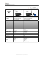
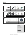
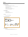
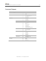
USER MANUAL Version 2.0 (2005.08) Promi-SD™ 101/202/205 Bluetooth RS232C Serial Adapter by Bluetooth Enabling Wireless Serial Communications 1 Promi–SD User Manual – Products z Promi-SD/ESD Series ESD01 ESD02 SD101 SD202 SD205 Bluetooth Serial Adapter Part Number IP11-320 IP11-321 IP10-300 IP10-301 IP10-302 Description Board-type wireless serial adapter with MMCX antenna connector Board-type wireless serial adapter with onboard antenna External type wireless serial adapter with internal battery External type wireless serial adapter External type wireless serial adapter with dip switch Power Class Class1 Class2 Class2 Class1 Class1 RF Range Up to 100m Up to 30m Up to 30m Up to 100m Up to 100m Power Connector Header 2.54m Header 2.54m DC plug or 9 pin DC plug or 9 pin DC plug or 9 pin Power supply 3.3V 3.3V 5V 5V~12V 5V~12V Serial connector 2.54mm Header 2.54mm Header 2x6 1x4x2 Female DB9 Female DB9 Female DB9 Serial Interface UART UART RS-232 RS-232 RS-232 Dip switch No No No No Yes (4 slots) Battery No No Yes No No Profile Serial Port Profile Serial Port Profile Serial Port Profile Serial Port Profile Serial Port Profile Applicable Antenna Stub Antenna Dipole Antenna Patch Antenna Stub Antenna Dipole Antenna Patch Antenna Stub Antenna Dipole Antenna Patch Antenna Stub Antenna Dipole Antenna Patch Antenna Stub Antenna Dipole Antenna Patch Antenna Bluetooth Qualified Fully Fully Fully Fully Fully Type Approved FCC CE FCC CE TELEC MIC CE FCC TELEC MIC CE FCC MIC CE FCC Dimensions (H¯W¯D) 27x27 18x20x11.7 62.5x31.2x16.3 62.5x31.2x16.3 62.5x31.2x16.3 Includes Stub Antenna Antenna Cable (15cm) Stub Antenna DC power cable AC/DC power adapter Stub Antenna DC power cable Stub Antenna DC power cable Develop Board Set DBS ESD01 or ESD02 use only Jig Board + Power Adaptor + RS232 Cable Part Number: IP30-500 © 2005 Initium Co., Ltd. All rights reserved Promi–SD User Manual – Products z Promi-MSP Series MSP102B MSP102A Wireless MultiSerial Adapter ¨ Part Number IP20-400 IP20-401 Wireless multi-serial adapter Wireless multi-serial adapter COM port redirector supported Serial/IP COM port redirector supported Serial/IP Up to 7 links simultaneously Up to 14 links simultaneously Power Class Class1 Class1 RF Range Up to 100m Up to 100m Power Connector DC plug DC plug Power supply 5V 5V Serial connector Male DB9 Male DB9 Serial Interface RS-232 RS-232 Dip switch No No Battery No No Profile LAN Access Dial-up Serial Port Profile LAN Access Dial-up Serial Port Profile Applicable Antenna Stub Antenna Dipole Antenna Patch Antenna Stub Antenna Dipole Antenna Patch Antenna Bluetooth Qualified Fully Fully Type Approved MIC CE FCC MIC CE FCC Dimensions (H¯W¯D) 147x112x32 147x112x32 Dipole Antenna AC/DC Power Adapter RS232 Cable LAN Cable Mounting Kit CD Dipole Antenna AC/DC Power Adapter RS232 Cable LAN Cable Mounting Kit CD Bluetooth USB Adapter Description Includes © 2005 Initium Co., Ltd. All rights reserved Promi–SD User Manual – Products z Accessories Antenna Power Supply Extension Cable SAT DAT PAT EAT IA60-800 IA60-801 IA60-802 IA60-820 Stub (30mm) Dipole (120mm) Patch (130¯90¯65mm) Board type (18¯6¯7mm) ESD01 use only EPA OPA UPA DPA IA70-840 IA70-841 IA70-860 IA70-861 External Power Adaptor Domestic use only External Power Adaptor International use USB power cable DC power cable RFC EEC SPC IA80-880 IA80-881 IA80-882 Antenna extension cable (1m) Antenna extension cable (15cm) ESD01 use only Serial power cable + Power adapter Ì For more information, please contact: Jinhyun Bae Marketing Manager Rm 901 Kins Tower 25-1 Jungja, Bundang Sungnam Kyunggi 463-120 South Korea +82 31 782-3232 (ext.102) +82 31 782-3231 Fax [email protected] [email protected] http://www.initium.co.kr © 2005 Initium Co., Ltd. All rights reserved Promi-SD User Manual – Table of Contents 1 Table of Contents Before Using the Product Welcome ------------------------------------------------------------- 3 Copyrights/Certification/Limited Liability ----------------- 3 Precautions and Safety ----------------------------------------- 3 General Terms and Conditions of Sale -------------------- 4 1. Getting Started Features of Promi-SD --------------------------------------------- 7 Components -------------------------------------------------------- 8 Assembly ------------------------------------------------------------- 8 Locating the Controls ------------------------------------------ 9 2. Configurations Operation Modes ------------------------------------------------- 12 LED Indicators ----------------------------------------------------- 13 Serial Ports ---------------------------------------------------------- 13 Reset to Factory Defaults ------------------------------------- 14 ---------------------------------------------------- 14 PromiWizard™ -------------------------------------------------------- 18 PromiWIN™ Terminal Program ------------------------------------------------ 20 Dip Switch (SD205 only) --------------------------------------- 21 Pairing Button (SD205 only) ---------------------------------- 22 3. Connections RS232 Interface Pin Assignment Power Supply --------------------------------------------------- 24 ---------------------------------------------------- 25 ------------------------------------------------------ 26 4. Trouble Shooting No Data Transmission ---------------------------------------------- 28 Data Loss or Malfunctioning ----------------------------------- 28 Transmission Delay ------------------------------------------------ 28 5. Specifications Bluetooth ----------------------------------------------------------- 30 Serial Interface --------------------------------------------------- 30 Power ---------------------------------------------------------------- 30 Mechanical Dimensions ---------------------------------------- 30 Environmental --------------------------------------------------- 30 Default Antenna ------------------------------------------------- 31 Power Consumption -------------------------------------------- 31 Wireless Coverage ---------------------------------------------- 31 Battery (SD101 only) --------------------------------------------- 31 Appendix A. AT Commands Terminology ------------------------------------------------------- A-2 Command Category ----------------------------------------- A-3 Command Description --------------------------------------- A-4 Command Validity ------------------------------------------- A-12 Appendix B. S-Register Appendix C. Type Approvals Appendix D. Technical Support © 2005 Initium Co., Ltd. All rights reserved Promi-SD User Manual – Before Using the Product 2 Before Using the Product z Welcome z Copyrights/Certification/Limited Liability z Precautions and Safety z General Terms and Conditions of Sale get UNWIRED, it’s easy! © 2005 Initium Co., Ltd. All rights reserved Promi-SD User Manual – Before Using the Product 3 Welcome Thank you for purchasing Promi-SD products. Promi-SD is a terminal device for wireless serial communication using Bluetooth technology, the international standard for short range wireless communications. Its interoperability and credibility delivers the maximum benefits of wireless communication. This user manual is designed to help you use the Promi-SD series properly. It is important that you read the manual to ensure that you get the most out of your products. Thank you. Copyrights/Certification/Limited Liability Ì Copyrights Initium Co., Ltd. has all the rights of the patent, trademark, literary property and intellectual property related to this manual. You may not copy or reproduce any part of this manual unless authorized by Initium Co., Ltd. You can be punished by using any part of this manual illegally. The companies, institutions, products, people and events used in examples are not real data. We don’t have any intension to be related with any companies, institutions, products, people and events through this manual and should not draw inferences. Users are responsible for observing the copyrights and intellectual properties. Ì Ì Certification Promi- MIC Bluetooth CE FCC TELEC SD101 c c c c c SD202 c c c c c SD205 c c c Limited Liability Neither the manufacturer, importers nor dealers is responsible for any accidental damage including bodily injury or any damage resulting from misuse or unsuitable operation by you. The information on this manual is prepared with the current product specifications. The manufacturer, Initium Co., Ltd., is adding new features to the product and may persistently apply new technologies hereafter. All standards may be changed at any time without notice. Precautions and Safety Ì Ì Electricity y Use only the supplied AC adapter. Use of unauthorized power adapter is not recommended. Electrical shock may result. y Do not kink or crease the power cable or place heavy objects on the power cable. Fire can result from damaged power cables. y Do not handle power plug and adapter with wet hands. Electrical shock may result. y Immediately power off the product and unplug the AC adapter if smoke or odors emit from the product and adapter. Fire can result from improper use. y Immediately power off the product and unplug the AC adapter if water or other liquids are present. Fire can result from improper use. Product © 2005 Initium Co., Ltd. All rights reserved Promi-SD User Manual – Before Using the Product 4 y Promi-SD meets the RS-232 standards. Do not wire with non-standard products. Damage to your products may result from improper use. y Do not drop or subject the device to impact. Damage to your products may result from improper use. y Keep away from harsh environments including humid, dusty, and smoky areas. Damage to your products may result from improper use. y Do not use excessive force on the buttons or attempt to disassemble the device. Damage to your products may result from improper use. y Do not place heavy objects on the product. Damage to your products may result from improper use. General Terms and Conditions of Sale 1. GENERAL. These general terms and conditions of sale (along with any associated written specification, quotation and/or supplemental terms and conditions provided by Seller) exclusively will govern the sale or licensing by Seller of all goods and services (including without limitation, hardware, firmware and software products, training, programming, maintenance, engineering, parts, repair and remanufacturing services – hereinafter, "Products") furnished to Buyer hereunder, whether such sale or licensing is effected by paper-based transactions or via facsimile or other forms of electronic data interchange or electronic commerce, and represents the entire agreement between Buyer and Seller with respect thereto. Buyer’s receipt or acceptance of delivery of any of the Products ordered or purchased hereunder will constitute its acceptance of these terms and conditions. No addition or modification to these terms and conditions will be binding on Seller unless agreed to in writing signed by an authorized representative at Seller’s headquarters. Seller objects to and rejects other terms and conditions that may be proposed by Buyer or that appear on or are referenced in Buyer’s purchase order or requisition that are in addition to or otherwise not consistent with the terms and conditions set forth or referenced herein. 2. WARRANTY. (a) Hardware: Seller warrants that new hardware Products furnished here-under will be free from defects in material, workmanship and design for a period of one (1) year from the date of invoice from Seller or its appointed distributor, as the case may be. Repaired or replacement Products provided as a result of this warranty subparagraph are similarly warranted for a period of six (6) months from the date of shipment to Buyer or the remainder of the original warranty term for that particular Product, whichever is longer. (b) Software and Firmware: Unless otherwise provided in a Seller or third party license, Seller warrants that standard software or firmware Products furnished hereunder, when used with Seller-specified hardware, will perform in accordance with published specifications prepared, approved, and issued by Seller for a period of one (1) year from the date of invoice from Seller or its appointed distributor, as the case may be. Seller makes no representation or warranty, express or implied, that the operation of the software or firmware Products will be uninterrupted or error free, or that the functions contained therein will meet or satisfy Buyer's intended use or requirements. (c) Non-Warranty Factory Remanufacture, Repair and Field Exchange: Seller warrants that non-warranty factory remanufactured or field exchanged hardware Products or repaired hardware Product components will be free from defects in material and workmanship for a period of one (1) year from the date of invoice from Seller or its appointed distributor, as the case may be. Repaired or replacement Products provided as a result of this warranty subparagraph are warranted for a period of thirty (30) days from the date of shipment to Buyer or the remainder of the original warranty term, whichever is longer. (d) Services: Seller warrants that Products comprised solely of services (e.g., training, on-site repair, engineering and custom application programming services) will be performed by appropriately skilled personnel employed or retained by Seller. (e) “Open Box” Products: Seller warrants that hardware Products sold as “Open Box” (e.g., customer and distributor returns, factory refurbished or reconditioned, etc.) will be free from defects in material and workmanship for a period of ninety (90) days from the date of invoice from Seller or its appointed distributor, as the case may be. “Open Box” Products, while serviceable, may not reflect the latest series or revision. Repaired or replacement Products provided as a result of this warranty subparagraph are similarly warranted for a period of thirty (30) days from the date of shipment to Buyer or the remainder of the original ninety-day warranty term for that particular Product, whichever is longer. (f) Buyer Specifications/Compatibility: Seller does not warrant and will not be liable for any design, materials, construction criteria or goods furnished or specified by Buyer (including that sourced from other manufacturers or vendors specified by Buyer). Any warranty applicable to such Buyer-specified items will be limited solely to the warranty, if any, extended by the original manufacturer or vendor directly or indirectly to Buyer. Seller does not warrant the compatibility of its Products with the goods of other manufacturers or Buyer’s application except to the extent expressly represented in Seller’s published specifications or written quotation. (g) Recyclable Materials: In keeping with environmental policies and practices, Seller reserves the right to utilize in its product manufacturing, repair and remanufacturing processes certain recyclable materials (e.g., fasteners, plastics and the like) or remanufactured parts equivalent to new in performance or parts which may have been subject to incidental use. However, such utilization will not affect any provided Product warranty or published reliability statistics. (h) Remedies: Remedies under the above warranties will be limited, at Seller’s option, to the replacement, repair, re-performance or modification of, or issuance of a credit for the purchase price, of the Products involved, and where applicable, only after the return of such Products pursuant to Seller's instructions. Replacement Products may be new, remanufactured, refurbished or reconditioned at Seller’s discretion. Buyer requested on-site warranty service (consisting of time, travel and expenses related to such services) will be at Buyer’s expense. The foregoing will be the exclusive remedies for any breach of warranty or breach of contract arising therefrom. (i) General: Warranty satisfaction is available only if (a) Seller is provided prompt written notice of the warranty claim and (b) Seller’s examination discloses that any alleged defect has not been caused by misuse; neglect; improper installation, operation, maintenance, repair, alteration or modification by other than Seller; accident; or unusual deterioration or degradation of the Products or parts thereof due to physical environment or electrical or electro-magnetic noise environment. (j) THE ABOVE WARRANTIES ARE IN LIEU OF ALL OTHER WARRAN-TIES AND CONDITIONS, WHETHER EXPRESSED, IMPLIED OR STATUTORY, INCLUDING IMPLIED WARRANTIES OF MERCHANTABILITY OR FITNESS FOR A PARTICULAR USE, OR PERFORMANCE OR APPLICATION WARRANTIES, TO THE FULLEST EXTENT PERMITTED BY APPLI-CABLE LAW. Rights under the above warranties (subject to noted limitations) extend to Buyer’s customers if Buyer is a Seller-appointed distributor for the Products. 3. DISCLAIMER AND LIMITATION OF LIABILITY. TO THE FULLEST EXTENT PERMITTED BY APPLICABLE LAW, SELLER WILL NOT BE LIABLE FOR ANY BUSINESS INTERRUPTION OR LOSS OF PROFIT, REVENUE, MATERIALS, ANTICIPATED SAVINGS, DATA, CONTRACT, GOODWILL OR THE LIKE (WHETHER DIRECT OR INDIRECT IN NATURE) OR FOR ANY OTHER FORM OF INCIDENTAL, INDIRECT OR CONSEQUENTIAL DAMAGES OF ANY KIND. SELLER'S MAXIMUM CUMULATIVE LIABILITY RELATIVE TO ALL OTHER CLAIMS AND LIABILITIES, INCLUDING OBLIGATIONS UNDER ANY INDEMNITY, WHETHER OR NOT INSURED, WILL NOT EXCEED THE COST OF THE PRODUCT(S) GIVING RISE TO THE CLAIM OR LIABILITY. SELLER DISCLAIMS ALL LIABILITY RELATIVE TO GRATUITOUS INFORMATION OR ASSISTANCE PROVIDED BY, BUT NOT REQUIRED OF SELLER HEREUNDER. ANY ACTION AGAINST SELLER MUST BE BROUGHT WITHIN EIGHTEEN (18) MONTHS AFTER THE CAUSE OF ACTION ACCRUES. THESE DISCLAIMERS AND LIMITATIONS OF LIABILITY WILL APPLY REGARDLESS OF ANY OTHER CONTRARY PROVISION HEREOF AND REGARDLESS OF THE FORM OF ACTION, WHETHER IN CONTRACT, TORT (INCLUDING NEGLIGENCE AND STRICT LIABILITY) OR OTHERWISE, AND FURTHER WILL EXTEND TO THE BENEFIT OF SELLER’S VENDORS, APPOINTED DISTRIBUTORS AND OTHER AUTHORIZED RESELLERS AS THIRD-PARTY BENEFICIARIES. EACH PROVISION HEREOF WHICH PROVIDES FOR A LIMITATION OF LIABILITY, DISCLAIMER OF WARRANTY OR CONDITION OR EXCLU-SION OF DAMAGES IS SEVERABLE AND INDEPENDENT OF ANY OTHER PROVISION AND IS TO BE ENFORCED AS SUCH. 4. INTELLECTUAL PROPERTY INDEMNITY. Except as excluded herein, Seller will defend any suit or proceeding brought against Buyer arising out of a claim that the design or construction of the Products sold or licensed hereunder by Seller infringes any patent, copyright or trademark granted or registered in the country of Seller’s shipping destination, provided (a) Buyer promptly notifies Seller in writing of any such claim and any suit or proceeding, (b) at Seller’s expense, Buyer gives Seller the sole right to defend, settle and control the defense of the suit or proceeding, (c) Buyer provides all necessary information and assistance for such defense or settlement, and (d) Buyer takes no position adverse to Seller in connection with such claim. In the event Seller is obligated to defend such suit or proceeding, Seller will pay all costs and damages finally awarded or agreed upon by Seller that are directly related thereto. Seller’s obligations under this paragraph will be fulfilled if Seller, at its option and expense: (i) procures for Buyer the right to continue using such Products, (ii) replaces the same with non-infringing equipment/software having functionality similar to that of the Products, (iii) modifies the Products to make them non-infringing while retaining similar functionality, or (iv) if (i)-(iii) are not commercially practicable, refunds to Buyer the purchase price of the affected Products in exchange for their return. Seller will have no obligation to defend or for any other liability with respect to: [a] any suit or proceeding to the extent based on or arising out of a configuration or modification made, specified or requested by Buyer and which is incorporated into or constitutes the Products, [b] the use of the Products in a process or application specified, requested or controlled by Buyer or any third parties, or [c] the use of the Products in combination with other © 2005 Initium Co., Ltd. All rights reserved Promi-SD User Manual – Before Using the Product 5 equipment, software or materials not supplied by Seller. As used in this paragraph, the term “Products” shall mean only Seller’s standard hardware and software that are generally commercially available, and expressly excludes third-party-branded equipment/software. THIS PARAGRAPH IS IN LIEU OF ALL WARRANTIES OR REPRESENTATIONS, WHETHER EXPRESS OR IMPLIED, THAT THE PRODUCTS WILL BE FREE OF THE RIGHTFUL CLAIM OF ANY THIRD PARTY BY WAY OF INFRINGEMENT OR THE LIKE. 5. RESALE OF THIRD-PARTY BRANDED PRODUCTS AND SERVICES. NOTWITHSTANDING ANY OTHER PROVISION HEREIN, SELLER MAKES NO REPRESENTATIONS, PROVIDES NO INDEMNITIES (INTELLECTUAL PROPERTY OR OTHERWISE), AND DISCLAIMS ALL WARRANTIES OF ANY KIND, EXPRESS OR IMPLIED RELATIVE TO ANY THIRD-PARTY BRANDED PRODUCT OR SERVICE (INCLUDING TRAINING) WHICH MAY BE RESOLD OR SUBLICENSED BY SELLER AS A DISCRETE ITEM HEREUNDER. 6. LICENSED SOFTWARE AND FIRMWARE. Use of Products comprised of software or firmware may be subject to Buyer’s acceptance of additional terms and conditions set forth in separate Seller or third-party license agreements that will control to the extent necessary to resolve any conflict with the terms and conditions stated or otherwise referenced herein. In the absence of a separate Seller’s license agreement, Buyer is granted a non-exclusive, non-transferable license to use provided Seller’s software or firmware only in object code form and solely in conjunction with Seller-provided Products, with no rights to sublicense, disclose, disassemble, decompile, reverse engineer, or otherwise modify the software or firmware. 7. PACKING AND MARKING. Buyer-specified packing or marking may be subject to additional charges not otherwise included in the price of the Products. 8. WEIGHTS AND DIMENSIONS. Published or advertised weights and dimensions are estimates or approximations only and are not warranted. 9. PRICES. Prices and other information shown in any Seller publication (including product catalogs and brochures) are subject to change without notice and to confirmation by specific quotation. Such publications are not offers to sell and are maintained only as a source of general information. Prices do not include sales, use, excise, customs, value-added or similar taxes. Buyer will pay or reimburse Seller for all such taxes as may be applicable. Time and material services will be provided in accordance with Seller’s published service rates (including applicable overtime and travel expenses) in effect as of the date such services are provided, unless otherwise confirmed by Seller’s written quotation or order acknowledgment. Billable service time includes travel time to and from the job site and all time Seller’s representatives are available for work and waiting (whether on or off the job site) to perform the services. 10. CHANGES AND SUBSTITUTIONS. Buyer-requested order changes, including those affecting the identity, scope and delivery of the Products, must be documented in writing and are subject to Seller’s prior approval and adjustments in price, scheduling and other affected terms and conditions. In any event, Seller reserves the right to reject any change that it deems unsafe, technically inadvisable or inconsistent with established engineering or quality guidelines and standards, or incompatible with Seller's design or manufacturing capabilities. Seller further reserves the right to substitute using the latest superseding revision or series or equivalent Product having comparable form, fit and function. 11. RETURNS. All returns of Products will be pursuant to Seller’s instructions. Non-warranty returns of unused and resalable Products for credit will be subject to Seller’s return policies in effect at the time, including applicable restocking charges and other conditions of return. Products returned under warranty must be properly packed and shipped to Seller-specified locations. Shipping containers must be clearly marked per Seller’s instruction and shipped freight prepaid by Buyer. Notwithstanding the foregoing, all sales of “Open Box” Products and any third-party branded products are final and do not qualify for non-warranty return. 12. ORDER CANCELLATION. Cancellation by Buyer prior to shipment is permitted only by written notice and upon payment to Seller of reasonable cancellation and restocking charges, including reimbursement for direct costs. Cancellation charges associated with orders for custom Products or Products specifically manufactured to Buyer’s specification may equal the actual selling price of the Products. Seller has the right to cancel an order for cause at any time by written notice, and Seller will be entitled to cancellation and restocking charges as identified above. No termination by Buyer for cause will be effective unless and until Seller has failed to correct such alleged cause within forty-five (45) days after receipt of Buyer’s written notice specifying such cause. 13. FORCE MAJEURE. Seller will not be liable for any loss, damage or delay arising out of its failure (or that of its subcontractors) to perform hereunder due to causes beyond its reasonable control, including without limitation, acts of God, acts or omissions of Buyer, acts of civil or military authority, fires, strikes, floods, epidemics, quarantine restrictions, war, riots, acts of terrorism, delays in transportation, or transportation embargoes. In the event of such delay, Seller’s performance date(s) will be extended for such length of time as may be reasonably necessary to compensate for the delay. 14. DISPUTES. The parties will attempt in good faith promptly to resolve any dispute arising hereunder by negotiations between representatives of the parties who have authority to settle the dispute. If unsuccessful, the parties further will attempt in good faith to settle the dispute by non-binding third-party mediation, with mediator fees and expenses apportioned equally to each side. Any dispute not so resolved by negotiation or mediation may then be submitted to a court of competent jurisdiction in accordance with the terms hereof. These procedures are the exclusive procedures for the resolution of all such disputes between the parties. 15. GOVERNING LAW AND FORUM. The agreement evidenced hereby and all disputes arising thereunder will be governed by and interpreted in accordance with the internal laws and will be subject to the exclusive jurisdiction of the courts of the state, province or other governmental jurisdiction in which Seller’s principal place of business resides, but specifically excluding the provisions of the 1980 UN Convention on Contracts for the International Sales of Goods. Should any term or provision hereof be held wholly or partly invalid or unenforceable under applicable law, the remainder of the agreement evidenced hereby will not be affected thereby. 16. ASSIGNMENT. The agreement evidenced hereby may not be assigned by either party without the written consent of the other (which consent will not be unreasonably withheld). However, consent will not be required for internal transfers and assignments as between Seller and its parent company, subsidiaries or affiliates as part of a consolidation, merger or any other form of corporate reorganization. 17. LANGUAGE. The parties acknowledge that they have required that the agreement evidenced hereby be drawn up in English. Les parties reconnaissent avoir exigé la rédaction en anglais du Contrat. In the event of a conflict between the English and other language versions, the English version will prevail. © 2005 Initium Co., Ltd. All rights reserved Promi-SD User Manual – 1. Getting Started 6 1. Getting Started z Features of Promi-SD z Components z Assembly z Locating the Controls get UNWIRED, it’s easy! © 2005 Initium Co., Ltd. All rights reserved Promi-SD User Manual – 1. Getting Started 7 Features of Promi–SD Ì Reliability and Interoperability Promi-SD is a terminal device for wireless serial communication using the Bluetooth technology that is international standard of short range wireless communications. Promi-SD accomplishes more reliable wireless communication. As Promi-SD can communicate with other Bluetooth devices, user may construct various communications with it. Promi-SD provides several models with different communication ranges from 30m (Promi-SD101) up to 100m (PromiSD202, 205) for user’s various applications. In terms of noise, Promi-SD delivers better quality of communication than standard RS232 cables. Ì Compact Design Promi-SD has the most compact design of the same kind devices and can be placed conveniently into any devices or equipments. Its detachable antenna of variety optimizes the quality and distance of wireless communications. Ì Easy Configuration and Adaptation Promi-SD can be configured and controlled by typical AT commands. User can easily configure Promi-SD on the terminal program such as HyperTerminal and implements the wireless communication without modifying user’s existing serial communication program. In addition to the basic AT commands, Promi-SD provides some expanded AT commands for its various functions. User friendly PromiWizard and PromiWIN are also provided for easy setup on Microsoft Windows. For Promi-SD205, user can setup the serial port parameters by dip switch without PC. Ì Security The FHSS (Frequency Hopping Spread Spectrum) technique of Bluetooth lets Promi-SD have less radio interference and no danger of hacking in air. Promi-SD also supports authentication and data encryption. Ì Benefits y No cable installation y Free from the environmental limitations y Easy relocation y Simple maintenance © 2005 Initium Co., Ltd. All rights reserved Promi-SD User Manual – 1. Getting Started 8 Components Stub Antenna Promi-SD101/SD202/SD205 DC 5V Power Cable Fig.1-1 Components of Promi-SD Please check the components of Promi-SD in Fig. 1-1 when purchasing. The picture of product may differ by models. The components of the package may change for improving product capacity or quality without notice. Assembly ※ Antenna is left-hand threaded. ※ Use of non-authorized power adapter is not recommended. Fig.1-2 Assembly of Promi-SD © 2005 Initium Co., Ltd. All rights reserved Promi-SD User Manual – 1. Getting Started 9 Locating the Controls Front Panel † Power Jack Back Label ‡ Power Switch Reset Button ※ SD101/SD202 has reset button on side. SD205 has it on front. Fig.1-3 Locating the Controls Ì Front Panel † y Promi-SD101/SD202 © 2005 Initium Co., Ltd. All rights reserved Promi-SD User Manual – 1. Getting Started y Ì 10 Promi-SD205 Back Label ‡ Model name & firmware version Product serial number Manufacturing year/month © 2005 Initium Co., Ltd. All rights reserved Promi-SD User Manual – 2. Configurations 11 2. Configurations z Operation Modes z LED Indicators z Serial Ports z Reset to Factory Defaults z PromiWizard™ z PromiWIN™ z Terminal Program z Dip Switch z Pairing Button get UNWIRED, it’s easy! © 2005 Initium Co., Ltd. All rights reserved Promi-SD User Manual – 2. Configurations 12 Operation Modes In addition to the serial port configurations such as bit/second, data bit, parity, stop bit, flow control, Promi-SD has some configurations for Bluetooth. For getting the most out of Promi-SD, user should understand the following Bluetooth connection schemes. A Bluetooth device can play a role as a master or slave. Master tries to connect itself to other Bluetooth device, and slave is waiting to be connected from other Bluetooth devices. A Bluetooth connection is always made by a pair of master and slave. A slave can be in two modes, Inquiry Scan or Page Scan mode. Inquiry Scan mode is waiting the packet of inquiry from other Bluetooth devices and Page Scan mode is waiting the packet of connection from other Bluetooth devices. Every Bluetooth device has its unique address, called BD (Bluetooth Device) address, which is composed of 12 hexa-decimal numbers. Promi-SD has 4 operation modes as follows. Each mode can be identified with LED indicators as illustrated in next section. Ì Mode0 Promi-SD must be in Mode0, when it is directly controlled by AT commands. In this mode, there is no response when power on or software reset, and Promi-SD is just waiting for AT command input. Neither master nor slave is assigned to Promi-SD in mode0. User can change the configurations of Promi-SD in this mode. The factory default is set to Mode0. Ì Mode1 Promi-SD tries to connect the last connected Bluetooth device. Promi-SD in Mode1 is to be a master and tries to connect the last connected Bluetooth device. Promi-SD always stores the BD address of the Bluetooth device to which Promi-SD has connected last time. When Promi-SD is initially used or after hardware reset, there is no BD address stored in Promi-SD. In this case, Mode1 does not make any sense and mode change from other operation modes to Mode1 is not allowed. The mode change to Mode1 can be made after Promi-SD succeeds to connect to other Bluetooth device in Mode0. Once changed to Mode1, Promi-SD will try to connect automatically the last connected Bluetooth device whenever power on or software reset. Promi-SD in Mode1 cannot be discovered or connected by other Bluetooth devices. Ì Mode2 Promi-SD is waiting for the connection from the last connected Bluetooth device. Promi-SD in Mode2 is to be a slave and waiting for the connection only from the last connected Bluetooth device. Just like Mode1, if there is no BD address stored in Promi-SD, the mode change from other operation modes to Mode2 is not allowed. Once changed to Mode2, Promi-SD will wait for the connection from the last connected Bluetooth device whenever power on or software reset. Promi-SD in Mode2 cannot be discovered or connected to Bluetooth devices other than the last connected device. Ì Mode3 Promi-SD is waiting for the connection from any other Bluetooth devices. Promi-SD in Mode3 acts like in Mode2, but allows any connection from other Bluetooth device. Most of general Bluetooth device is set to Mode3. Promi-SD in Mode3 can be discovered and connected from any other Bluetooth devices. © 2005 Initium Co., Ltd. All rights reserved Promi-SD User Manual – 2. Configurations 13 LED Indicators Ì Ì Promi-SD101/SD202 Indicator Power LED Status LED Mode0 Green ┏━━━━━━━ Red Mode1 Green ┏━━━━━━━ Green (every 1 sec) Mode2 Green ┏━━━━━━━ Green (every 3 sec) ┏┰┓ Mode3 Green ┏━━━━━━━ Green (every 3 sec) ┏┰┓ Connected Green ┏━━━━━━━ Green ┏━━━━━━━ ┏┓ ┏━━━━━━━ Promi-SD205 Indicator Power LED Standby LED Mode0 Green ┏━━━━━━━ Red Mode1 Green ┏━━━━━━━ Connect LED ┏━━━━━━━ Green (every 1 sec) ┏┓ Mode2 Green ┏━━━━━━━ Green (every 3 sec) ┏┰┓ Mode3 Green ┏━━━━━━━ Green (every 3 sec) ┏┰┓ Connected Green ┏━━━━━━━ Green ┏━━━━━━━ RS232-Tx and RS232-Rx LED are blinking accordingly when data is transmitted. For small data transmission, it may be hard to recognize the quick blinking. Serial Ports The applicable settings for serial ports are as follows. Serial Port Settings Values Baud rate 1200, 2400, 4800, 9600 , 19200, 38400, 57600, 115200, 230400 Data bit 8 Parity No parity , Even parity, Odd parity Stop bit 1,2 Hardware Flow Control Use , No use The values in box are the factory defaults. Ì Data Bit Promi-SD supports only 8 data bit. In the case of 7 data bit, please contact the technical support. Ì Hardware Flow Control Promi-SD plugged into its host system transmits data from host to the other side Bluetooth device. These data is saved temporarily in the internal buffer of Promi-SD and sent repeatedly until the transmission is completed packet by packet. When the radio transmission condition is not good enough to send data promptly, it can cause the transmission delay. If the host sends more data when the buffer is full, buffer overflow will make Promi-SD malfunction consequently. In order to prevent this buffer overflow, Promi-SD works as follows. © 2005 Initium Co., Ltd. All rights reserved Promi-SD User Manual – 2. Configurations 14 In case of using hardware flow control, Promi-SD makes RTS be ‘disable’ to stop receiving further data from the host when the buffer becomes full. RTS will be ‘able’ to begin receiving data again from the host when the buffer has some room for more data. In case of not using hardware flow control, Promi-SD clears the buffer to secure the room for next data when the buffer becomes full. This means the loss of data. As the transmission data becomes large, the possibility of data loss goes higher. For large data transmission, use of hardware flow control is highly recommended. Reset to Factory Defaults To turn back all the configurations to its factory settings, press the reset button depicted in Fig. 1-3. Press the reset button with a narrow pointed tool like paper clip longer than 1 second. Reset works only when power is on. Configuration Software Configuration Software Usage Operating Platform PromiWizard Automatic connection of a pair of Promi-SD’s MS Windows 98SE or higher PromiWIN Individual setup of Promi-SD MS Windows 98SE or higher This configuration software comes with the product, which also can be downloaded from http://www.initium.co.kr. PromiWizard PromiWizard is a Wizard program for the configuration of a pair of Promi-SD’s to make automatic connection between them afterwards. To make connection with Bluetooth devices other than Promi-SD, use PromiWIN or AT commands on a terminal program. For convenience sake, we call two Promi-SD’s SD1 and SD2 respectively. Install and run PromiWizard. Plug SD1 into the serial port of host computer and power on. Status (Promi-SD101/202) or Standby (Promi-SD205) LED will be lit in red. It may be blinking in green if SD1 has different settings from factory defaults. Click [Wizard Setting] button to configure the serial port settings of SD1. These settings must be same as those of the host system, to which SD1 is used. Click [Next], then Status (Promi-SD101/202) or Standby (Promi-SD205) LED will be lit in red. © 2005 Initium Co., Ltd. All rights reserved Promi-SD User Manual – 2. Configurations 15 Click [Next] with marking in the check box. SD1 becomes in Scan mode, in which SD1 can be discovered and connected from other Bluetooth device. Status (Promi-SD101/202) or Standby (Promi-SD205) LED will blink twice in green every 3 seconds. Take SD2 out of the host computer. Be careful to keep the power on. Now, plug SD2 into the serial port of the host computer and power on. Click [Wizard Setting] button to configure the serial settings of SD2. These settings must be same as those of the host system, to which SD2 is used. Click [Next], then Status (Promi-SD101/202) or Standby (Promi-SD205) LED will be lit in red. Click [Next] with marking in the check box. Status (Promi-SD101/202) or Standby (Promi-SD205) LED will blink in green. SD2 begins to search nearby Bluetooth devices for 30 seconds. The program will show the Bluetooth devices with Device Address, Device Name and CoD (Class of Device). © 2005 Initium Co., Ltd. All rights reserved Promi-SD User Manual – 2. Configurations 16 Select SD1 and click [Connect], then the following message box will be shown. It takes about 5 seconds to complete connection. SD1 and SD2 now have each other’s BD address. Status (PromiSD101/202) or Standby (Promi-SD205) LED’s of both SD1 and SD2 will be lit in green. For the automatic connection between SD1 and SD2 when power off and on, operation mode of SD1 and SD2 have to be set respectively. © 2005 Initium Co., Ltd. All rights reserved Promi-SD User Manual – 2. Configurations 17 Set the operation mode of SD2 to Mode1. SD2 is working as a master trying to connect itself to SD1. Take SD2 out of the host computer and plug SD1 into the serial port again. Set the operation mode of SD1 to Mode2. SD1 is working as a slave waiting for the connection from SD2. Now the configuration of SD1 and SD2 has been completed. When power off and on both of them, they will make connection again automatically. © 2005 Initium Co., Ltd. All rights reserved Promi-SD User Manual – 2. Configurations 18 PromiWIN PromiWIN is a program running on Microsoft Windows for the configuration of Promi-SD. Install PromiWIN on your computer. Plug a Promi-SD into the serial port of the computer and turn on the power. Run PromiWIN. Set each option properly and click [Confirm]. If the settings are different from the host computer, error message will pop up. If the Promi-SD is in the status of connection, warning message will pop up. Then the current connection can be cancelled by [연결 해제] button on the main window. © 2005 Initium Co., Ltd. All rights reserved Promi-SD User Manual – 2. Configurations 19 Serial port settings can be changed by <Start Configuration> and <PromiWIN Configuration> of PromiWIN in the menu bar at upper left corner of the window without re-running the PromiWIN program. The icons in the left side window come to the corresponding windows. In device configuration window, hardware reset can be executed or operation mode and RS232 can be configured as well. Security option also can be configured in this window. Promi-SD has 4 response messages, ‘OK’, ‘ERROR’, ‘CONNECT’, and ‘DISCONNECT’. In some cases, these responses can affect the host system unexpectedly. To prevent this, user can set the response to ON or OFF. For Promi-SD205, hardware flow control can be configured only by dip switch. Thus H/W Flow Control option will not work in this case. Click [Apply] button to reflect the given options to Promi-SD actually. Connect icon will show the following window to search and connect other Bluetooth devices. © 2005 Initium Co., Ltd. All rights reserved Promi-SD User Manual – 2. Configurations 20 Click [Search] button to search nearby Bluetooth devices. The maximum number of devices to be searched can be controlled. Select one of the devices searched and click [Connect] button. The selected Bluetooth device must be in Page scan mode. Click [연결 해제] button to cancel the connection normally. Connection(in) icon will show the following window to make Promi-SD wait to a connection from the other Bluetooth device. The waiting time in seconds can be controlled. With 0 input for this waiting time, Promi-SD keeps waiting for connection until [Cancel] button is clicked. Terminal Program A terminal program is an application that will enable a PC to communicate directly with a modem. If you are using Windows 98SE or higher version of Windows, HyperTerminal program as it is included as part of the operating system. Promi-SD provides some extended AT commands for its configurations on terminal program. This manual will explain the method using HyperTerminal. If you need to install HyperTerminal, click start>setting>control panel>add/remove programs. For more precise information, please refer to Help of Microsoft Windows. Attach Promi-SD to serial port of host computer and power on. Check Status LED (Promi-SD101/202) or Standby LED (Promi-SD205) is lit in green. Launch HyperTerminal. It can be found in start >programs >accessories >communication >HyperTerminal. Select the Serial port that Promi-SD will be connected to. Input the same settings into Serial port configuration window as Promi-SD settings. The settings need to be set correctly, otherwise, error message may be shown up on the screen or cause malfunctioning of Promi-SD. © 2005 Initium Co., Ltd. All rights reserved Promi-SD User Manual – 2. Configurations 21 Choose the settings in File->Properties->Settings->ASCII setup that let you turn echo on in HyperTerminal; this will show the response Promi-SD sends on the screen. You now get the HyperTerminal window where you are able to control Promi-SD with AT commands. For expanded AT commands that Promi-SD provides, please refer to Appendix A. AT commands. Example of AT commands: AT+BTINFO? 000B53000509,PSDv2a-000509,MODE0,STANDBY,0,0,HWFC OK AT+BTINQ? 000B5320007E,PSDv2a-20007E,001F00 0004B300E205,AP2002:1 #0,020300 OK ATD000B53000509 OK CONNECT 000B53000509 Dip Switch (Promi-SD205 only) This feature is only on Promi-SD205. With the combination of 4 slot dip switches, baud rate and hardware flow control can be set simply without host computer. Reset Button Dip Switch Pairing Button © 2005 Initium Co., Ltd. All rights reserved Promi-SD User Manual – 2. Configurations 22 Upper 3 dip switches are used for setting baud rate, and bottom dip switch is used for setting hardware flow control option. If the baud rate needs to be set out of the range given below, PromiWIN or terminal program should be used for extended AT commands. At this time combination of dip switches must be complied with AT cmd. Then baud rate will go back to 9600 as default. Baud Rate 2400 Hardware Flow Control 4800 9600 No use 19.2K 38.4K 57.6K 115.2K AT cmd Use Handshaking Pairing Button (Promi-SD205 only) Promi-SD205 provides Pairing Button for instant configuration without PC to make an automatic connection between two Promi-SD205s. For convenience sake, name two Promi-SD205s as SD1 and SD2 respectively. 1. Turn off all the nearby Promi-SD/ESD. 2. Turn on SD1 and SD2 and hardware reset both of them by pressing Reset Button. 3. Press the Pairing Button of SD1 for 2 seconds until Standby LED of SD1 blinks 3 times every 3 seconds. Keep the power ON. 4. Press the Pairing Button of SD2 for 2 seconds until Standby LED turns off and Connect LED blinks 3 times every 2 seconds. Now press again the Pairing Button for 2 seconds until Connect LED blinks every 0.5 second. 5. Wait for SD1 & SD2 to be connected for a while until Connect LED’s of SD1 and SD2 is lit in green. It takes about 30 seconds to make a connection. If there are many Bluetooth devices nearby, it will take a little bit more. 6. Turn SD1 off and on. Connect LED blinks twice in green every 3 seconds. 7. Turn SD2 off and on. Connect LED blinks once in green every 1 second. 8. Now a pair of Promi-SD205 is configured to make automatic connection, whenever power off and on. 9. Just use this pair of Promi-SD205 like virtual serial cable. © 2005 Initium Co., Ltd. All rights reserved Promi-SD User Manual – 3. Connections 23 3. Connections z RS232 Interface z Pin Assignment z Power Supply get UNWIRED, it’s easy! © 2005 Initium Co., Ltd. All rights reserved Promi-SD User Manual – 3. Connections 24 RS232C Interface Ì RS232C In the early 1960s, a standards committee, today known as the Electronic Industries Association, developed a common interface standard for data communications equipment. At that time, data communications was thought to mean digital data exchange between a centrally located mainframe computer and a remote computer terminal, or possibly between two terminals without a computer involved. These devices were linked by telephone voice lines, and consequently required a modem at each end for signal translation. While simple in concept, the many opportunities for data error that occur when transmitting data through an analog channel require a relatively complex design. It was thought that a standard was needed first to ensure reliable communication, and second to enable the interconnection of equipment produced by different manufacturers, thereby fostering the benefits of mass production and competition. From these ideas, the RS232 standard was born. It specified signal voltages, signal timing, signal function, a protocol for information exchange, and mechanical connectors. Refer the following site for details; http://www.camiresearch.com/Data_Com_Basics/RS232_standard.html Ì DTE/DCE If the full EIA232 standard is implemented as defined, the equipment at the far end of the connection is named the DTE device (Data Terminal Equipment, usually a computer or terminal), has a male DB9 connector. Equipment at the near end of the connection (the telephone line interface) is named the DCE device (Data Circuit-terminating Equipment, usually a modem), has a female DB9 connector. The cable linking DTE and DCE devices is a parallel straight-through cable with no cross-overs or self-connects in the connector hoods. If all devices exactly followed this standard, all cables would be identical, and there would be no chance that an incorrectly wired cable could be used. Ì DB9 Female Promi-SD is a DCE device compatible with RS232 standard, having DB9 female interface. Pin # Signal Direction Description 1 CD Output Received Line Signal Detect 2 TxD Output Transmitted Data 3 RxD Input Received Data 4 DSR Input DTE Ready 5 GND - 6 DTR Output 7 CTS Input 8 RTS Output 9 Vcc Input Signal Ground DCE Ready Clear to Send Request to Send Ring Indicator © 2005 Initium Co., Ltd. All rights reserved Promi-SD User Manual – 3. Connections 25 Pin Assignment Ì To Host with DTE Interface Ì To Host with DCE Interface DCE (Host System) DCE (Promi-SD) 1 CD 1 CD 2 TxD 2 TxD 3 RxD 3 RxD 4 DSR 4 DSR 5 GND 5 GND 6 DTR 6 DTR 7 CTS 7 CTS 8 RTS 8 RTS 9 Vcc 9 Vcc © 2005 Initium Co., Ltd. All rights reserved Promi-SD User Manual – 3. Connections 26 Power Supply Promi-SD can be supplied power through the power jack and through pin 9 of DB9 connector. Ì Through Power Jack DC 5 ~ 12V, Min. 150mA power should be supplied through DC power cable. Red cable is positive and black one is negative. Electrical Polarity Red + Black DC Power Cable AC/DC power adaptor and USB power cable are also available to supply power. AC/DC Power Adapter Ì USB Power Cable Through Pin 9 of DB9 connector The power can be supplied through pin 9 of DB9 connector. Because Promi-SD does not have any protection circuit from surge, it must be constant voltage of 5 ~ 12V. © 2005 Initium Co., Ltd. All rights reserved Promi-SD User Manual – 4. Trouble Shooting 27 4. Trouble Shooting z No Data Transmission z Data Loss or Malfunctioning z Transmission Delay get UNWIRED, it’s easy! © 2005 Initium Co., Ltd. All rights reserved Promi-SD User Manual – 4. Trouble Shooting 28 No Data Transmission Ì COM Port Settings Check whether the Baud rate of Promi-SD is same as that of its host equipment. If you do not know the current Baud rate of Promi-SD, initialize it to 9600 by pressing Reset Button. Check whether the Data bit is set to 8. Promi-SD supports only 8 Data bit. If your host equipment uses 7 Data bit and even or odd parity, it can work as if it uses 8 Data bit and No parity. This is valid only when both DCE devices are PromiSD. In this case, set both Promi-SDs to 8 Data bit and No parity. If one of DCE devices is other Bluetooth device such as Bluetooth USB dongle, please contact Technical Support. Check whether the Parity and Stop bit of Promi-SD are same as those of its host equipment. Promi-SD supports No parity, Even parity and Odd parity, 1 and 2 Stop bit. Check whether the host equipment of Promi-SD uses Hardware Flow Control. Promi-SD is initially set to Use of Hardware Flow Control. If your host equipment does not use Hardware Flow Control, set the Hardware Flow Control of Promi-SD to No use. Promi-SD does not support RS-232 break signal. Ì Pin Assignment Promi-SD is DCE device. If your host equipment is DTE, plug Promi-SD directly to the host equipment or use straight RS232 cable. If your host equipment is DCE, use cross over RS-232 cable (Null modem cable). Data Loss or Malfunctioning Ì Hardware Flow Control When transmitting large data with No use of Hardware Flow Control, Promi-SD will clear the data buffer unexpectedly. This possibility goes higher as the RF transmission environment is bad. Ì SD Response The messages of SD response may affect the function of host system. Set ATS10=0 not to send SD response to host system and try again. Refer Appendix B. for details. Transmission Delay Ì RF Processing Delay It takes 30msec approximately for a Promi-SD to complete the data transmission to the other side Bluetooth device. This time delay cannot be reduced and would be bigger as the RF transmission environment is bad. Do not use Promi-SD If your applications cannot allow this time delay. Ì RF Transmission Environment If there are lots of Bluetooth device working in a small area and/or the RF communication distance is too long and/or there are some obstacles affecting RF performance, Promi-SD repeats the transmission packet by packet due to interferences and/or low RF performance. This leads the transmission time delay. © 2005 Initium Co., Ltd. All rights reserved Promi-SD User Manual – 5. Specifications 29 5. Specifications z Bluetooth z Serial Interface z Power z Mechanical Dimensions z Environmental z Default Antenna z Power Consumption z Wireless Coverage z Battery get UNWIRED, it’s easy! © 2005 Initium Co., Ltd. All rights reserved Promi-SD User Manual – 5. Specifications Ì Ì Ì Ì 30 Bluetooth Interface y Bluetooth 1.1 specification compatible and qualified y Protocol: RFCOMM, L2CAP, SDP y Profiles: Serial Port Profile, Generic Access Profile, Service Discovery Profile y Radio Frequency: 2.4 ~ 2.4738GHz y Number of Channels: 79 y Transmission Power Class 2 (Promi-SD101) y Transmission Power Class 1 (Promi-SD202/SD205, ESD) y Data Transmission Rate: 380Kbps Max. Serial Interface y EIA RS232C Standard y Connector: DB9 female y Data Transmission Rate: 1,200 ~ 230,400bps y Hardware Flow Control: On/Off Power y DC 5 ~ 12V Constant Voltage y Supply: DC Jack or Pin 9 of DB9 Mechanical Dimensions 16mm 63mm Ì 35mm 30mm Environmental y Recommended Operational Temperature: -20℃ ~ 70℃ y Recommended Operational Humidity: 90% Max. Non-condensing © 2005 Initium Co., Ltd. All rights reserved Promi-SD User Manual – 5. Specifications Ì Ì 31 Default Antenna y Type: Helical y Frequency: 2,400 ~ 2,485GHz y Gain: Max. 1dBi ±1 y Impedance: 50Ω y size: 30mm¯9mm (W¯D) y weight: 3.5g Power Consumption The power consumption varies according to the operation status of Promi-SD. The table below shows the average measuring results in different operation modes with 1m communication distance. Consumption Operation Status SD202 Not plugged into Serial port 17mA Plugged into Serial port 31mA Inquiry Scan 106mA Page Scan 106mA Inquiry & Page Scan 64mA Connected as Master device 60mA Connected as Slave device 37mA Connected in Park mode as Master device 33mA Connected in Park mode as Slave device 32mA Connected and Transmitting Data at 9600bps 66mA Connected and Transmitting Data at 115200bps 80mA The power consumption will be increased as the communication distance is getting longer, but never exceeds 106 ㎃ in any case. Ì Wireless Coverage The table below shows the average measuring results in open space. These results can vary according to the environmental conditions. Antennas for two Promi-SD units Ì Maximum Distance Maximum Distance (SD202/205) (SD101) Stub Antenna – Stub Antenna 100m 30m Stub Antenna - Dipole Antenna 150m 50m Dipole Antenna - Dipole Antenna 200m 80m Patch Antenna - Dipole Antenna 400m 150m Patch Antenna - Patch Antenna 1,000m 300m Battery (SD101 only) y Type: Lithium-Ion y Capacity: 3.8V, 190mAh y Protector: Temperature and current voltage protection y Charging Time: 1Hour 45 Minutes ±15Minutes y Full-load Runtime: 5Hours when transmitting data at 115200kbps © 2005 Initium Co., Ltd. All rights reserved Promi-SD User Manual – 5. Specifications y Can be charged up to 500 times approximately © 2005 Initium Co., Ltd. All rights reserved 32 Promi-SD User Manual – Appendix A. AT Commands A-1 Appendix A. AT Commands z Terminology z Command Category z Command Description z Command Validity get UNWIRED, it’s easy! © 2005 Initium Co., Ltd. All rights reserved. Promi-SD User Manual – Appendix A. AT Commands A-2 Terminology Ì AT Command AT command set is the de facto standard language for controlling modems. The AT command set was developed by Hayes and is recognized by virtually all personal computer modems. Promi-SD provides the extended AT command set to control and configure the serial parameters and Bluetooth connection. Ì AT Response Promi-SD replies to AT commands with 4 kinds of message, ‘OK’, ‘ERROR’, ‘CONNECT’ and ‘DISCONNECT’. Ì Ì Ì Ì Operation Mode y Mode0: Waiting for AT commands y Mode1: Attempting to connect to the last connected Bluetooth device y Mode2: Waiting for the connection from the last connected Bluetooth device y Mode3: Waiting for the connection from any other Bluetooth devices Operation Status y Standby: Waiting for AT commands y Pending: Executing tasks y Connect: Transmitting data Security y Authentication: Pin code (or Pass key) y Encryption: Data encryption Symbols The symbols are used for the description of command syntax as follows: Symbol Meaning ASCII Code Carriage return 0x0D Line feed 0x0A Carriage return + Line feed 112233445566 Bluetooth device address n or m One digit decimal number to Timeout in second © 2005 Initium Co., Ltd. All rights reserved. Promi-SD User Manual – Appendix A. AT Commands A-3 Command Category Command Category Index RESET SERIAL PORT BLUETOOTH Information 1 ATZ 2 AT&F 3 AT 4 AT+UARTCONFIG,b,p,s 5 AT+USEDIP? 6 AT+BTINFO? 7 AT+BTINQ? 8 AT+BTLAST? Mode 9 AT+BTMODE,n Status 10 +++ 11 AT+SETESC,nn 12 ATO 13 AT+BTCANCEL 14 AT+BTSCAN 15 AT+BTSCAN,n,to 16 AT+BTSCAN112233445566,to 17 ATD 18 ATD112233445566 19 ATH 20 AT+BTKEY=$string 21 AT+BTSD? 22 AT+BTCSD 23 AT+BTFP,n 24 AT+BTSEC,a,e 25 AT+BTNAME=$string 26 AT+BTLPM,n 27 AT&V 28 ATSnn? 29 ATSnn=mm Connection Security Miscellaneous S-REGISTER AT commands © 2005 Initium Co., Ltd. All rights reserved. Promi-SD User Manual – Appendix A. AT Commands Command Description 1 ATZ SD Response OK Purpose Software Reset Description This is the same effect as power off and on. This command disconnects Bluetooth device, and stops ongoing task. After rebooting, the status is decided by the preset operation mode. Some AT commands need ATZ to take effect. Reference AT&F, AT+BTCSD, AT+UARTCONFIG 2 AT&F SD Response OK Purpose Hardware reset Description This is the same effect as initialization by reset button. All parameters are initialized to factory defaults. The storage of Promi-SD is cleared completely. Reference ATZ 3 AT SD Response OK Purpose Check the connection status with host equipment Description Check if the connection to host equipment is normal. The serial parameters of Promi-SD must be same as those of host equipment. If not, SD response is none or ‘ERROR’ or abnormal sequence of strings. Reference AT+UARTCONFIG, ATZ, AT&F 4 AT+UARTCONFIG,Baudrate,Parity,Stopbit SD Response OK Purpose Set Serial parameters Parameters Baudrate=1200/2400/9600/14400/19200/38400/57600/115200/230400 (Default=9600) Parity=N/E/O (Default=N) Stopbit=1/2 (Default=1) Description The Serial parameters can be set or changed. The factory default is 9600, N, 1. To take effect of this command, ATZ or power off and on. Reference AT, ATZ, AT&F, ATS Example AT+UARTCONFIG,38400,E,1 5 AT+USEDIP? (SD205 only) © 2005 Initium Co., Ltd. All rights reserved. A-4 Promi-SD User Manual – Appendix A. AT Commands SD Response m Purpose Check the Baud rate set by dip switch Description m=0: Set to ‘AT cmd’ m=1: Set to other than ‘AT cmd’ Reference AT, ATZ, AT&F, ATS 6 AT+BTINFO? SD Response 112233445566,DeviceName,Mode,Status,Auth,Encryp,FlowControl OK Purpose Display Bluetooth settings Description The current Bluetooth settings are displayed including BD address, Device name, Operation mode, Operation status, Authentication, Data Encryption, and Hardware Flow Control. The initial value of Device name is ‘PSDv3b-445566’. PSD stands for PromiSD, v3b for the version of firmware, and 445566 for the last 6 digits of BD address. Mode=MODE0/MODE1/MODE2/MODE3 Status=STANDBY/PENDING/CONNECT Auth=0/1 (Authentication is not activated when 0) Encrypt=0/1 (Encryption is not activated when 0) FlowControl=HWFC/NoFC Reference AT+BTNAME, AT+BTMODE, AT+BTSEC, ATS14? Example 000B530011FF,INITIUM,MODE0,PENDING,1,1,HWFC 7 AT+BTINQ? SD Response 112233445566,FriendlyName,CoD 112233445566,FriendlyName,CoD 112233445566,FriendlyName,CoD OK Purpose Search Bluetooth devices nearby Description The Bluetooth devices in Inquiry scan mode nearby are displayed with their BD addresses, Device names, and Class of device. Maximum 10 devices are scanned for 30 seconds. Reference AT+BTSCAN, ATD, AT+BTINFO? 8 AT+BTLAST? SD Response 112233445566 OK Purpose Display the BD address of the last connected device Description The Bluetooth device connected to this Promi-SD last time is displayed with its BD address. Reference AT+BTSCAN, ATD, AT+BTINFO?, AT+BTINQ? 9 AT+BTMODE,n SD Response OK © 2005 Initium Co., Ltd. All rights reserved. A-5 Promi-SD User Manual – Appendix A. AT Commands Purpose Set operation mode Parameters n=0: MODE0 (Default) n=1: MODE1 n=2: MODE2 n=3: MODE3 Description When the operation status is ‘Pending’ currently, change the status to ‘Standby’ with AT+BTCANCEL prior to this command. To take effect of this command, ATZ or power off and on. Reference Example AT+BTINFO? AT+BTMODE,2 OK ATZ 10 +++ SD Response OK Purpose Convert the operation status of ‘Connect’ to ‘Standby’ Description In ‘Connect’ status, data from host is transmitted to the other side Bluetooth device, and any AT command is not accepted but this command, which is not echoed on the screen. When Promi-SD encounters a character ‘+’ from host, it stops the data transmission and waits for next 2 characters. If the next 2 characters are both ‘+’, it restart to transmit data including the first ‘+’ as well. If not, it converts the operation status to ‘Standby’. If the data from host includes ‘+++’, it will convert the operation status to ‘Standby’ unexpectedly. Notice that Promi-SD holds data transmission when it encounters ‘+’, until receiving next character. ‘+’ is an escape sequence character by default, which is changeable by AT+SETESC. Reference AT+SETESC, ATO, AT+BTCANCEL 11 AT+SETESC,nn SD Response OK Purpose Change the escape sequence character Parameters nn=Decimal number of ASCII code (Default=43) Description Escape sequence character set to ‘+’ by default is changeable. The parameter nn must be a printable character. Reference +++, ATO Example AT+SETESC,42 12 ATO SD Response None Purpose Convert the operation status of ‘Standby’ to ‘Connect’ Description You can convert the operation status of ‘Standby’ to ‘Connect’ ready to transmit data. Reference +++, AT+SETESC © 2005 Initium Co., Ltd. All rights reserved. A-6 Promi-SD User Manual – Appendix A. AT Commands 13 AT+BTCANCEL SD Response OK Purpose Terminate a current executing task Description This terminates a current executing task, such as Inquiry scan and Page scan, then converts the operation status to ‘Standby’. Reference AT+BTSCAN, ATD, AT+BTINQ? 14 AT+BTSCAN SD Response OK CONNECT 112233445566 Purpose Wait for inquiry and connection from other Bluetooth devices Description This allows the inquiry and connection from the other Bluetooth devices. The operation status will be in ‘Pending’ after this command. When connection is made and released, the operation status is back to ‘Pending’. To convert the operation status to ‘Standby’ AT+BTCANCEL must be used. This has the same effect as AT+BTSCAN,3,0. When connection is made with other Bluetooth device, SD response will be ‘CONNECT’ with its BD address. Reference ATD, AT+BTINQ?, AT+BTCANCEL 15 AT+BTSCAN,n,to SD Response OK CONNECT 112233445566 or OK ERROR Purpose Wait for inquiry and connection from other Bluetooth devices for a given duration Parameters n=1: Allows Inquiry scan n=2: Allows Page scan n=3: Allows both of Inquiry scan and Page scan to= Time duration in seconds Description For the given to, Promi-SD is waiting for the inquiry and connection from other Bluetooth devices. If the parameter of to is 0, it will wait forever. When connection is made with other Bluetooth device, SD response will be ‘CONNECT’ with its BD address. If there is no connection made within this time duration, SD response is ‘ERROR’ and the operation status becomes to ‘Standby’. Reference ATD, AT+BTINQ?, AT+BTCANCEL Example AT+BTSCAN,2,30 16 AT+BTSCAN112233445566,to SD Response OK CONNECT 112233445566 or OK ERROR © 2005 Initium Co., Ltd. All rights reserved. A-7 Promi-SD User Manual – Appendix A. AT Commands Purpose Wait for connection by the Bluetooth device with given BD address Parameters 112233445566=BD address to= time duration in seconds Description For the given to, Promi-SD is waiting for the connection from the Bluetooth device with the given BD address. If the parameter of to is 0, it will wait forever. When connection is made with the Bluetooth device, SD response will be ‘CONNECT’ with its BD address. If there is no connection made within this time duration, SD response is ‘ERROR’ and the operation status becomes to ‘Standby’. Reference ATD, AT+BTINQ?, AT+BTCANCEL Example AT+BTSCAN000B530011FF,30 17 ATD SD Response OK CONNECT 112233445566 or OK ERROR Purpose Connect to the last connected Bluetooth device Description Promi-SD saves the BD address of the Bluetooth device most recently connected. ATD can make connection to it without input its BD address. If it fails to make connection, SD response is ‘ERROR’. Reference AT+BTINQ?, AT+BTSCAN 18 ATD112233445566 SD Response OK CONNECT 112233445566 or OK ERROR Purpose Connect to the Bluetooth device with given BD address Parameters 112233445566=BD address Description Promi-SD attempts to connect to the Bluetooth device with the given BD address. To make successful connection, the Bluetooth device must be in Page scan. This attempt continues for 5 minutes. If it fails to make connection, SD response is ‘ERROR’. Reference AT+BTINQ?, AT+BTSCAN Example ATD000B530011FF 19 ATH SD Response OK DISCONNECT Purpose Release the current connection Description The current Bluetooth connection is released normally. It takes about 30 seconds to detect an abnormal disconnection such as power off and moving out of service range. Reference ATD, AT+BTSCAN © 2005 Initium Co., Ltd. All rights reserved. A-8 Promi-SD User Manual – Appendix A. AT Commands 20 AT+BTKEY=$string SD Response OK Purpose Change pin code Parameters $string= New pin code (Default=”1234”) Description Pin code is a string, which allows 16 alpha-numeric characters maximum. Based on this pin code, Promi-SD generates a link key which is used in actual authentication process. Reference AT+BTCSD, AT+BTFP, AT+BTSD?, AT+BTSEC, ATZ, AT&F Example AT+BTKEY=”apple” 21 AT+BTSD? SD Response 112233445566 OK Purpose Display the list of Bluetooth devices sharing the pin code Description Once a connection is made with pin code, Promi-SD saves the Bluetooth device with its link key generated by pin code. The connection to a device listed in Promi-SD can be made automatically without authentication process. The maximum number of the list is 5. Reference AT+BTCSD, AT+BTFP, AT+BTKEY, AT+BTSEC, ATZ, AT&F 22 AT+BTCSD SD Response OK Purpose Clear the list of Bluetooth devices sharing the pin code Description This clears the list of Bluetooth devices with link key in flash memory. To take effect of this command, ATZ or power off and on because the main memory still has the list. Reference AT+BTFP, AT+BTKEY, AT+BTSD?, AT+BTSEC, ATZ, AT&F 23 AT+BTFP,n SD Response OK Purpose Set generation of link key every time of connection Parameters n=0: Inactivate (Default) n=1: Activate Description If n is set to 1, Promi-SD asks pin code every time of connection. This is used to level up the security. Reference AT+BTCSD, AT+BTKEY, AT+BTSD?, AT+BTSEC, ATD, ATZ, AT&F 24 AT+BTSEC,Authentication,Encryption SD Response OK Purpose Set authentication and data encryption Parameters Authentication=0: Inactivate (Default) Authentication=1: Activate Encryption=0: Inactivate (Default) Encryption=1: Activate © 2005 Initium Co., Ltd. All rights reserved. A-9 Promi-SD User Manual – Appendix A. AT Commands Description If the authentication is activated, the pin code must be set by AT+BTKEY command. Data encryption cannot be used when authentication is not activated, i.e. Authentication=0 and Encryption=1 is not valid. Reference AT+BTCSD, AT+BTFP, AT+BTSD?, AT+BTSD?, ATZ, AT&F 25 AT+BTNAME=$string SD Response OK Purpose Change device name Parameters $string= New device name (Default=”PSDv3b-445566”) Description Promi-SD can have a user friendly name to identify easily. The name allows 30 alphanumeric characters maximum. Reference AT+BTINFO?, AT+BTINQ? Example AT+BTNAME=”My-Promi-SD” 26 AT+BTLPM,n SD Response OK Purpose Set low power mode Parameters n=0: Inactivate (Default) n=1: Activate Description During no data transmission, Promi-SD can be in low power mode to save the power consumption. It takes a few seconds to wake up Promi-SD in low power mode. 27 AT&V SD Response S0:m0;S1:m1; …Sn:mn OK Purpose Display all the S-register Description All parameters are stored at S-register in flash memory. These values are sustained until hardware reset. Reference ATS 28 ATSnn? SD Response value OK Purpose Display a given S-register Parameters nn= Address of S-register Description A specific S-register is displayed. Reference AT&V 29 ATSnn=mm SD Response OK © 2005 Initium Co., Ltd. All rights reserved. A-10 Promi-SD User Manual – Appendix A. AT Commands Purpose Parameters Change S-register value nn= Address of S-register mm= New value of S-register Description Some S-registers are optimized for the overall performance and protected from an arbitrary change by user. When users try to change these S-registers, SD response is ‘ERROR’. For details of S-register, refer Appendix. B. Reference AT&V Example ATS10=0 © 2005 Initium Co., Ltd. All rights reserved. A-11 Promi-SD User Manual – Appendix A. AT Commands A-12 Command Validity Operation Status AT Command Standby Pending AT ○ ○ ATZ ○ ○ AT&F ○ ○ AT+BTINQ? ◎ ATD112233445566 ◎ ATD ◎ AT+BTSCAN ◎ AT+BTSCAN,n,to ◎ AT+BTSCAN112233445566,to ◎ AT+BTCANCEL Connect ○ +++ ○ AT+SETESC ◎ ATO ● ATH ● AT+BTSEC,Auth,Encr ◎ AT+BTLAST? ○ AT+BTMODE,n ◎ AT+BTNAME="Name" ◎ AT+BTKEY="nnnn" ◎ AT+BTINFO? ○ AT+BTLPM,n ◎ AT+BTSD? ○ AT+BTCSD ◎ AT+BTFP,n ◎ AT+UARTCONFIG,b,p,s ◎ AT+USEDIP? ○ ◎ Valid only when Promi-SD is not connected to other Bluetooth device. ● Valid only when Promi-SD is connected to other Bluetooth device. © 2005 Initium Co., Ltd. All rights reserved. ○ ○ ○ ○ Promi-SD User Manual – Appendix B. S-Register B-1 Appendix. B S-Register get UNWIRED, it’s easy! © 2005 Initium Co., Ltd. All rights reserved. Promi-SD User Manual – Appendix. B S-Register B-2 S-Register S-registers contain 46 parameters of Promi-SD. These are stored in flash memory and sustained the values unless hardware reset is executed. The value of S-register can be accessed and changed with ATS command by user. Some S-registers not shown below are set to maximize the performance of Promi-SD. Thus it is not recommended to change these S-registers. Change the value of S-register only in Standby status. Ì S1: Force to Reconnect (default 1) S1=0, Promi-SD in Mode1 does not try reconnection when disconnected. S1=1, Promi-SD in Mode1 keeps trying reconnection when disconnected. Ì S3: Stream UART Policy (default 0) S3=0, the priority of UART streaming is throughput. S3=1, the priority is latency, which minimizes the delay of data transmission. This is useful in case of transmiting very small data quickly. Ì S4: Enable Remote Name Query (default 1) S4=0, Promi-SD inquires only BD address. This speeds up the inquiry process. S4=1, Promi-SD inquire BD address, device name and class of device. Ì S10: Enable SD Response (default 1) S10=0, Promi-SD does not send SD responses to host system. S10=1, Promi-SD send SD responses to host system. Ì S11: Enable Escape (default 1) S11=0, Promi-SD does not allow escape sequence character. The operation status of Connect cannot be changed to Standby. As Promi-SD skips the process detecting escape sequence character, the more efficient data transmission is expected. S11=1, Promi-SD allow escape sequence character. Whenever it is needed, the Connect status can be changed to Standby. Ì S12: Clear Data Buffer When Disconnected (default 0) S12=0, Promi-SD does not clear the data buffer received from host system when disconnected. S12=1, Promi-SD clears the data buffer when disconnected. Ì S14: Enable DTR Transfer (default 1, SD202/205 only) S14=0, DTR/DSR signal is transferred to loop-back. S14=1, DTR signal is transferred to DSR of remote device. Ì S15: Enable Disconnect by DTR (default 0, SD202/205 only) S15=0, DTR signal cannot release the connection. S15=1, The connection can be released when DTR signal is off. Ì S24: Maximum Number of Inquiry Result (default 10) The maximum number of inquiry list can be controlled. © 2005 Initium Co., Ltd. All rights reserved. Promi-SD User Manual – Appendix. B S-Register Ì B-3 S28: Escape Sequence Character (default 43) The decimal number of the ASCII code of escape sequence character can be controlled. The initial value is 43, the ASCII code of ‘+’. Ì S29: Error Code The most recent error code is stored in this register. User cannot change this value. Ì S31: Page Timeout (default 300) This is the timeout in seconds to attempt connection with ATD command. Ì S33: Inquiry Timeout (default 30) This is the timeout in seconds to execute inquiry scan. Ì S37: Supervision Timeout (default 16000) This is the timeout in 625µsec to presume disconnection, which is set to 16000 initially. 16000¯625µsec=10sec) The smaller the value becomes, the more quickly Promi-SD can detect an abnormal disconnection. But when the communication is suspended for some environmental reasons, it may be regarded as disconnection. Ì S46: BD Address of Last Connected Device This saves the BD address of the Bluetooth device connected most recently. © 2005 Initium Co., Ltd. All rights reserved. Promi-SD User Manual – Appendix C. Type Approvals C-1 Appendix C. Type Approvals get UNWIRED, it’s easy! © 2005 Initium Co., Ltd. All rights reserved. Promi-SD User Manual – Appendix C. Approvals © 2005 Initium Co., Ltd. All rights reserved. C-2 Promi-SD User Manual – Appendix C. Approvals © 2005 Initium Co., Ltd. All rights reserved. C-3 Promi-SD User Manual – Appendix C. Approvals © 2005 Initium Co., Ltd. All rights reserved. C-4 Promi-SD User Manual – Appendix C. Approvals © 2005 Initium Co., Ltd. All rights reserved. C-5 Promi-SD User Manual – Appendix C. Approvals © 2005 Initium Co., Ltd. All rights reserved. C-6 Promi-SD User Manual – Appendix C. Approvals © 2005 Initium Co., Ltd. All rights reserved. C-7 Promi-SD User Manual – Appendix D. Technical Support D-1 Appendix D. Technical Support get UNWIRED, it’s easy! © 2005 Initium Co., Ltd. All rights reserved. Promi-SD User Manual – Appendix D. Technical Support D-2 Use this form to request technical support for Promi-SD. Individual form should be filled out for each Promi-SD in question. Referring to the example on separate sheet, please provide as much information as possible so we may resolve and respond to your inquiry promptly. When you have finished, submit this form by e-mail to [email protected] or by fax to +82 31 7823231. NOTE: Before you contact technical support, please have a look at our FAQ. Chances are, you will find an instant answer to your problem. 3 indicates a required field. Ì User Contact Information Name 3 Company E-mail 3 Phone 3 Fax 3 Ì Overall Hardware Setup 3 (Depict or describe actual hardware connections) Ì Host Device (to which Promi-SD is attached) Description 3 Serial Port Port Parity 3 Setup Baud Rate 3 Stop Bits 3 Data Bits 3 Flow Control 3 Comments Ì Promi-SD Model Name 3 BD Address* 3 S-Register** 3 * BD Address is the 6-digit number labeled on the product. ** As for S-Register, the values are shown by “AT&V” command on a PC running Serial Port program (e.g. HyperTerminal). See the User’s Manual for details. © 2005 Initium Co., Ltd. All rights reserved. Promi-SD User Manual – Appendix D. Technical Support D-3 Ì Pin Assignment to Promi-SD Promi-SD Ì Host Device Direction Signal Pin # Pin # Out CD 1 ÅÆ Out TxD 2 ÅÆ In RxD 3 ÅÆ In DSR 4 ÅÆ ─ GND 5 ÅÆ Out DTR 6 ÅÆ In CTS 7 ÅÆ Out RTS 8 ÅÆ In Vcc 9 ÅÆ Signal Direction Bluetooth Connection: This Promi-SD is connected to (mark one) an another Promi-SD a Promi-ESD a Promi-MSP others Model 3 Manufacture Application S/W Ì Environment for RF Communication Distance* 3 Obstacles** 3 Ì Problems you have * Distance is a linear distance between Promi-SD and the other side Bluetooth device. ** Obstacles are things affecting RF performance in the middle of Promi-SD and the other side Bluetooth device, such as walls, partitions, other equipments, etc. © 2005 Initium Co., Ltd. All rights reserved.