1
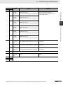
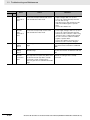
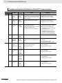
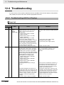
12 Troubleshooting and Maintenance 12-4 Troubleshooting If an error occurs in the machine, determine the error conditions from the error displays and operation state, identify the cause of the error, and take appropriate measures. 12-4-1 Troubleshooting with Error Displays Error List Error No. (hex) Main Sub 11 0 12 0 Name Cause Control Power Supply Undervoltage Overvoltage The voltage between the positive and negative terminals in the control power supply converter dropped below the specified value. 100-V products: Approx. 70 VDC (Approx. 30 VAC) 200-V products: Approx. 145 VDC (Approx. 100 VAC) 400-V products: Approx. 15 VDC • The power supply voltage is low. A momentary power interruption occurred. • Insufficient power supply capacity: the power supply voltage dropped because there was inrush current when the main power supply was turned ON. • The Servo Drive is faulty (circuit fault). Measure the voltage between the L1C and L2C lines on the connectors and the terminal block. The power supply voltage exceeded the allowable input voltage range, causing the voltage between the positive and negative terminals in the converter to exceed the specified value. The power supply voltage is high. The voltage was suddenly increased by the phase advance capacitor or the uninterruptible power supply (UPS). 100-V products: Approx. 200 VDC (Approx. 140 VAC) 200-V products: Approx. 400 VDC (Approx. 280 VAC) 400-V products: Approx. 800 VDC (Approx. 560 VAC) • The Regeneration Resistor wiring is broken. Measure the voltage between the connector (L1, L2, and L3) lines. Input the correct voltage. Remove the phase advance capacitor. • The External Regeneration Resistor is inappropriate and cannot absorb all of the regenerative energy. The load inertia is too large, gravitational torque on the vertical axis is too large, or there is some other problem to absorb the regenerative energy. • The Servo Drive is faulty (circuit fault). 12-14 Measures • Increase the power supply voltage. Change the power supply. • Increase the power supply capacity. • Replace the Servo Drive. • Use a tester to measure the resistance of the external resistor between the B1 and B2 terminals on the Servo Drive. If the resistance is infinite, the wiring is broken. Replace the external resistor. • Change the regeneration resistance and wattage to the specified values. (Calculate the regenerative energy and connect an External Regeneration Resistor with the required regeneration absorption capacity. Reduce the descent speed.) • Replace the Servo Drive. G5-series AC Servomotors and Servo Drives User’s Manual (with Built-in EtherCAT Communications) 12 Troubleshooting and Maintenance Error No. (hex) Main Sub 13 0 Cause Measures Main Circuit Power Supply Undervoltage (Undervoltage between positive and negative terminals) If the Undervoltage Error Selection (3508 hex) is set to 1, a momentary power interruption occurred between L1 and L3 for longer than the value specified for the Momentary Hold Time (3509 hex). Alternatively, the voltage between the positive and negative terminals in the main power supply converter dropped below the specified value while the servo was ON. 100-V products: Approx. 80 VDC (Approx. 55 VAC) 200-V products: Approx. 110 VDC (Approx. 75 VAC) 400-V products: Approx. 180 VDC (Approx. 125 VAC) • The power supply voltage is low. Measure the voltage between the connector (L1, L2, and L3) lines. • A momentary power interruption occurred. Main Power Supply Undervoltage (AC • Insufficient power supply capacity: the interruption power supply voltage dropped because detected) there was inrush current when the main power supply was turned ON. • Phase-failure: a Servo Drive with 3-phase input specifications was operated with single-phase power supply. • Check the setting of the Momentary Hold Time (3509 hex). Set each phase of the power supply correctly. • Increase the power supply capacity. Refer to 2-3-1 Servo Drive Model Table on page 2-8 for information on the power supply capacity. • Connect each phase (L1, L2, and L3) of the power supply correctly. Use L1 and L3 for single-phase 100 V and single-phase 200 V. • Replace the Servo Drive. 12 • Increase the power supply voltage. Change the power supply. Eliminate the cause of the failure of the electromagnetic contactor on the main circuit power supply, and then turn ON the power again. G5-series AC Servomotors and Servo Drives User’s Manual (with Built-in EtherCAT Communications) 12-15 12-4-1 Troubleshooting with Error Displays • The Servo Drive is faulty (circuit fault). 12-4 Troubleshooting 1 Name 12 Troubleshooting and Maintenance Error No. (hex) Main Sub 14 0 Name Cause Overcurrent The current flowing through the converter exceeded the specified value. • The Servo Drive is faulty (faulty circuit, faulty IGBT part, etc.). • The Servomotor cable is short-circuited between phases U, V, and W. • The Servomotor cable is ground-faulted. • Motor windings are burned out. 1 IPM Error • The Servomotor wiring contacts are faulty. • The relay for the dynamic brake has been welded due to frequent servo ON/OFF operations. • The Servomotor is not suitable for the Servo Drive. • The command input timing is the same as or earlier than the Servo ON timing. • The resistance of the connected External Regeneration Resistor is less than the minimum allowable value. 15 12-16 0 Servo Drive Overheat The temperature of the Servo Drive radiator or power elements exceeded the specified value. • The ambient temperature of the Servo Drive exceeded the specified value. • Overload Measures • Disconnect the Servomotor cable, and turn ON the servo. If the problem immediately recurs, replace the Servo Drive with a new one. • Check to see if the Servomotor cable is short-circuited between phases U, V and W by checking for loose wire strands on the connector lead. Connect the Servomotor cable correctly. • Check the insulation resistance between phases U, V, and W of the Servomotor cable and the grounding wire of the Servomotor. If the insulation is faulty, replace the Servomotor. • Check the balance between the resistance of each wire of the Servomotor. If resistance is unbalanced, replace the Servomotor. • Check for missing connector pins in Servomotor connections U, V, and W. If any loose or missing connector pins are found, secure them firmly. • Replace the Servo Drive.Do not turn the servo ON for 3 minutes after using the dynamic brake. • Check model (capacity) of the Servomotor and the Servo Drive on the nameplates. Replace the Servomotor with a Servomotor that matches the Servo Drive. • Wait at least 100 ms after the servo has been turned ON, then input commands. • Connect an External Regeneration Resistor whose resistance is more than the minimum allowable value. • Improve the ambient temperature and the cooling conditions of the Servo Drive. • Increase the capacities of the Servo Drive and the Servomotor. Set longer acceleration and deceleration times. Reduce the load. G5-series AC Servomotors and Servo Drives User’s Manual (with Built-in EtherCAT Communications) 12 Troubleshooting and Maintenance Error No. (hex) Main Sub 16 0 Name Overload Measures When the feedback value for torque command exceeds the overload level specified in the Overload Detection Level Setting (3512 hex), overload protection is performed according to the overload characteristics. • The load was heavy, the effective torque exceeded the rated torque, and operation continued too long. • Vibration or hunting occurred due to faulty gain adjustment. The Servomotor vibrates or makes unusual noise. The Inertia Ratio (3004 hex) setting is faulty. • The Servomotor wiring is incorrect or broken. • The machine was hit by an object, or the machine load suddenly became heavy. The machine was distorted. • The electromagnetic brake remains ON. Check if torque (current) waveforms oscillate or excessively oscillates vertically during analog output or communications. Check the overload warning display and the load rate through communications. • Increase the capacities of the Servo Drive and the Servomotor. Set longer acceleration and deceleration times. Reduce the load. • Readjust the gain. 12 • Connect the Servomotor cable as shown in the wiring diagram. Replace the cable. • Remove the distortion from the machine. Reduce the load. • • Measure the voltage at the brake terminals. Turn OFF the brake. • Wire the Servomotor and the encoder correctly so that the wiring matches the axes. Refer to 3-2 Overload Characteristics (Electronic Thermal Function) on page 3-35 for information on overload characteristics. 18 0 Regeneration The regenerative energy exceeds the Overload processing capacity of the Regeneration Resistor. • The regenerative energy during deceleration caused by a large load inertia increased the converter voltage, and then insufficient energy absorption by the Regeneration Resistor further increased the voltage. • The Servomotor rotation speed is too high to absorb the regenerative energy within the specified deceleration time. • The operating limit of the external resistor is limited to a 10% duty. Check the load rate of the Regeneration Resistor through communications. This Regeneration Resistor cannot be used for continuous regenerative braking. • Check the operation pattern (speed monitor). Check the load rate of the Regeneration Resistor and check for the excessive regeneration warning display. Increase the capacities of the Servo Drive and the Servomotor, and length the deceleration time. Use an External Regeneration Resistor. • Check the operation pattern (speed monitor). Check the load rate of the Regeneration Resistor and the excessive regeneration warning display. Increase the capacities of the Servo Drive and the Servomotor, and lengthen the deceleration time. Reduce the Servomotor rotation speed. Use an External Regeneration Resistor. • Set the Regeneration Resistor Selection (3016 hex) to 2. Precautions for Correct Use Always provide a temperature fuse or other protective measure when setting the External Regeneration Resistor Setting (3017 hex) to 2. Otherwise, the Regeneration Resistor will not be protected, generate excessive heat, and be burnt. 1 Regeneration The Servo Drive regeneration drive Tr is Tr Error faulty. Replace the Servo Drive. G5-series AC Servomotors and Servo Drives User’s Manual (with Built-in EtherCAT Communications) 12-17 12-4-1 Troubleshooting with Error Displays • When multiple machines were wired, the wiring was incorrect and the Servomotor cable to was connected to a Servomotor for another axis. 12-4 Troubleshooting Cause 12 Troubleshooting and Maintenance Error No. (hex) Name Cause Measures Main Sub 21 0 Encoder Communicati ons Disconnectio n Error A disconnection was detected because communications between the encoder and the Servo Drive were stopped more frequently than the specified value. Wire the encoder correctly as shown in the wiring diagram. Correct the connector pin connections. 1 Encoder Communicati ons Error There was a communications error in data from the encoder. There was a data error mainly due to noise. The encode cable is connected, but a communications data error occurred. • Provide the required encoder power supply voltage 5 VDC 5% (4.75 to 5.25 V). Be careful especially when the encode cable is long. • If the Servomotor cable and the encoder cable are bundled together, separate them. • Connect the shield to FG. 23 0 Encoder Communicati ons Data Error No communications error occurred with the data from the encoder, but there is an error in the contents of the data. There was a data error mainly due to noise. The encode cable is connected, but a communications data error occurred. • Provide the required encoder power supply voltage 5 VDC 5% (4.75 to 5.25 V). Be careful especially when the encode cable is long. • If the Servomotor cable and the encoder cable are bundled together, separate them. • Connect the shield to FG. 24 0 Error Counter Overflow Position error pulses exceeded the setting of the Following error window (6065 hex). • Motor operation does not follow the command. • Check to see if the Servomotor rotates according to the position command pulse. Check on the torque monitor to see if the output torque is saturated. Adjust the gain. Maximize the set values on the Positive torque limit value (60E0 hex) and the Negative torque limit value (60E1 hex). Wire the encoder as shown in the wiring diagram. Lengthen the acceleration and deceleration times. Reduce the load and the speed. • Increase the set value of object 6065 hex. • The value of the Following error window (6065 hex) is small. 1 Excessive Speed Deviation Error The difference (speed deviation) between Motor Velocity Demand Value After Filtering and actual speed has exceeded the set value of the Excessive Speed Deviation Setting (3602 hex). Note When Motor Velocity Demand Value After Filtering is forced to 0 during an immediate stop due to halt or forward/ reverse drive prohibition input, the speed deviation immediately increases The speed deviation also increases when the Motor Velocity Demand Value After Filtering starts. Therefore, provide enough margin when making the settings. 12-18 • Increase the set value of object 3602 hex. • Lengthen the acceleration time of the Motor Velocity Demand Value After Filtering. Alternatively, improve the tracking (following) performance by adjusting the gain. • Disable the Excessive Speed Deviation Setting. (3602 hex = 0) G5-series AC Servomotors and Servo Drives User’s Manual (with Built-in EtherCAT Communications) 12 Troubleshooting and Maintenance Error No. (hex) Main Sub 25 0 During fully-closed control, the difference between the load position from the external encoder and the Servomotor position from the encoder was larger than the number of pulses set as the Hybrid Following Error Counter Overflow Level (3328 hex). Measures • Check the Servomotor and load connection. • Check the external encoder and Servo Drive connection. • When moving the load, check to see if the change in the Servomotor position (encoder feedback value) has the same sign as the change in the load position (external encoder feedback value). Check to see if the External Feedback Pulse Dividing Numerator and Denominator (3324 hex and 3325 hex), and External Feedback Pulse Direction Switching (3326 hex) are set correctly. 0 Overspeed The Servomotor rotation speed exceeded the value set on the Overspeed Detection Level Setting (3513 hex). 1 Overspeed 2 The Servomotor rotation speed exceeded the value set for the Overspeed Detection Level Setting at Immediate Stop (3615 hex). 1 Absolute Value Cleared The multi-rotation counter for the absolute encoder was cleared during USB communications by the CX-Drive. • Check to see if the multi-rotation counter for the absolute encoder was cleared during USB communications by the CXDrive. Note This operation is performed for safety and is not an error. ABS • Do not give excessive speed commands. • Check the input frequency, dividing ratio, and multiplication ratio of the command pulse. • If overshooting occurred due to faulty gain adjustment, adjust the gain. • Wire the encoder as shown in the wiring diagram. 4 Command Error The position command variation after the electronic gear is higher than the specified value. • Check to see if the position command variation is large. • Check the electronic gear ratio. • Check to see if the backlash compensation amount is too large. 5 Command Generation Error During position command processing, an error such as an “over the calculation range” error occurred. Check to see if the electronic gear ratio, and the acceleration and deceleration rates meet the restrictions. 6 Operation Command Duplicated An attempt was made to establish EtherCAT communications (change from Init to PreOperational state) or to turn ON the servo from the controller (enable operation) while executing an FFT that operates with the Servo Drive alone or a trial run. Check to see if EtherCAT communications is established or the servo is turned ON (enable operation) while an FFT or a trial run was being conducted. 7 Position Data Initialized A Config operation was performed or the multi-rotation counter was cleared for the absolute encoder during EtherCAT communications. Check to see if Config operation was performed or the multi-rotation counter was cleared for the absolute encoder during EtherCAT communications. Note: This operation is performed for safety and is not an error. G5-series AC Servomotors and Servo Drives User’s Manual (with Built-in EtherCAT Communications) 12-19 12 12-4-1 Troubleshooting with Error Displays 27 Excessive Hybrid Deviation Error Cause 12-4 Troubleshooting 26 Name 12 Troubleshooting and Maintenance Error No. (hex) Main Sub 29 1 Name Cause Measures Error Counter Overflow 1 The value that is obtained by dividing the absolute encoder position (in pulses) by the electronic gear ratio exceeded 231 (2,147,483,648) during the initialization of position data, after the control power was turned ON in absolute value mode, after a Config operation, after FFT was executed, or after a trial run was executed. Review the operation range of the absolute external encoder position and the electronic gear ratio. ABS 2 Error Counter Overflow 2 The position error in pulses exceeded 229 (536,870,912). Alternatively, the position error in command units exceeded 230 (1,073,741,824). • Check to see if the Servomotor rotates according to the position command. • Check on the torque monitor to see if the output torque is saturated. • Adjust the gain. • Maximize the set values on the Positive torque limit value (60E0 hex) and the Negative torque limit value (60E1 hex). • Wire the encoder as shown in the wiring diagram. 30 (st) 0 Safety Input Error At least one of the input photocouplers for safety inputs 1 and 2 turned OFF. Check the input wiring of safety inputs 1 and 2. 33 0 Interface Input Duplicate Allocation Error 1 There is a duplicate setting in the input signal (IN1, IN2, IN3, and IN4) function allocations. Allocate the functions to the connector pins correctly. 1 Interface Input Duplicate Allocation Error 2 There is a duplicate setting in the input signal (IN5, IN6, IN7, and IN8) function allocations. 2 Interface Input Function Number Error 1 There is an undefined number specification in the input signal (IN1, IN2, IN3, and IN4) function allocations. Alternatively, a logic setting error was detected. 3 Interface Input Function Number Error 2 There is an undefined number specification in the input signal (IN5, IN6, IN7, and IN8) function allocations. Alternatively, a logic setting error was detected. 4 Interface Output Function Number Error 1 There is an undefined number specification in the output signal (OUTM1) function allocation. 5 Interface Output Function Number Error 2 There is an undefined number specification in the output signal (OUTM2) function allocation. 8 External Latch Input Allocation Error There is an error in the latch input function allocation. • The function was allocated to input signals other than IN5, IN6, or IN7. • The function was allocated to NC. • The function was not allocated for all control modes. 12-20 G5-series AC Servomotors and Servo Drives User’s Manual (with Built-in EtherCAT Communications) 12 Troubleshooting and Maintenance Error No. (hex) Main Sub 34 0 Name The Servomotor exceeded the allowable operating range set in the Overrun Limit Setting (3514 hex) with respect to the position command input range. • The gain is not appropriate. • The set value of object 3514 hex is too small. 36 0 Object Error Object Corrupted EEPROM write verification data was corrupted when the power supply was turned ON and data was read from the EEPROM. The Servo Drive is faulty. Replace the Servo Drive. Return the Servo Drive to the dealer that it was purchased from and ask for investigation and repair. 0 Drive Prohibition Input Error 1 When the Drive Prohibition Input Selection (3504 hex) was set to 0, both the Forward Drive Prohibition Input (POT) and the Reverse Drive Prohibition Input (NOT) turned ON. When object 3504 hex was set to 2, either the Forward Drive Prohibition input or the Reverse Drive Prohibition input turned ON. Check for any problems with the switches, wires, and power supplies that are connected to the Forward Drive Prohibition input or the Reverse Drive Prohibition input. In particular, check to see if the control signal power supply (12 to 24 VDC) turned ON too slowly. 1 Drive Prohibition Input Error 2 When object 3504 hex was set to 0, EtherCAT communications were interrupted and either POT or NOT was ON, an operation command (such as a trial run or FFT) was received from the CX-Drive. Conversely, POT or NOT turned ON while operation was being performed for a CXDrive operation command. 0 Absolute encoder system down error The voltage of the built-in capacitor dropped below the specified value because the power supply to the encoder or the battery power supply was down. Connect the battery power supply, and then clear the absolute encoder. Unless the absolute encoder is cleared, the error cannot be reset. The multi-rotation counter of the encoder exceeded the specified value. • Set the Operation Switch When Using Absolute Encoder (3015 hex) to an appropriate value. • Make sure that the traveling distance from the origin of the machine is no more than 32,767 revolutions. The Servomotor rotation speed exceeded the specified value when only the battery power supply was used during a power interruption. • Check the power supply voltage (5V 5%) on the encoder side. • Check the connections to connector CN2. Unless the absolute encoder is cleared, the error cannot be reset. An encoder initialization error was detected. Replace the Servomotor. 0 1 2 40 ABS 41 0 Absolute Encoder Counter Overflow Error ABS 42 0 Absolute Encoder Overspeed Error ABS 43 0 Encoder Initialization Error G5-series AC Servomotors and Servo Drives User’s Manual (with Built-in EtherCAT Communications) 12-21 12 12-4-1 Troubleshooting with Error Displays • Reset all of the objects. • If this error occurs repeatedly, the Servo Drive may be faulty. In this case, replace the Servo Drive. Return the Servo Drive to the dealer that it was purchased from and ask for investigation and repair. 2 38 • Check the gains (the balance between position loop gain and speed loop gain) and the inertia ratio. • Increase the set value of object 3514 hex. Alternatively, set object 3514 hex to 0 to disable the protection function. Data in the Object Save Area was corrupted when the power supply was turned ON and data was read from the EEPROM. 1 37 Measures 12-4 Troubleshooting Overrun Limit Error Cause 12 Troubleshooting and Maintenance Error No. (hex) Main Sub 44 0 Name Cause Absolute Encoder 1-rotation Counter Error Measures The encoder detected a 1-rotation counter error. Replace the Servomotor. The encoder detected a multi-rotation counter error. Replace the Servomotor. The rotation of the encoder was higher than the specified value when the power supply was turned ON. Do not let the Servomotor move when the power supply is turned ON. ABS 45 0 Absolute Encoder Multi-rotation Counter Error ABS 47 0 Absolute Encoder Status Error ABS 48 0 Encoder Phase-Z Error A missing serial incremental encoder phase- Replace the Servomotor. Z pulse was detected. The encoder is faulty. 49 0 Encoder CS Signal Error A logic error was detected in the CS signal for serial incremental encoder. The encoder is faulty. Replace the Servomotor. 50 0 External Encoder Connection Error A disconnection was detected because communications between the external encoder and the Servo Drive were interrupted more than the specified number of times. Wire the external encoder correctly as shown in the connection diagram. Correct the connector pin connections. 1 External Encoder Communicati ons Data Error There was a communications error in data from external encoder. There was a data error mainly due to noise. The external encoder connection cable is connected, but a communications data error occurred. • Provide the required external encoder power supply voltage 5 VDC 5% (4.75 to 5.25 V). Be careful especially when the external encoder connection cable is long. • If the Servomotor cable and the external encoder connection cable are bundled together, separate them. • Connect the shield to FG. Refer to the external encoder connection diagram. 12-22 G5-series AC Servomotors and Servo Drives User’s Manual (with Built-in EtherCAT Communications) 12 Troubleshooting and Maintenance Error No. (hex) Name Cause Measures Sub 51 0 External Encoder Status Error 0 Bit 0 of the external encoder error code (ALMC) was set to 1. Refer to the external encoder specifications. 1 External Encoder Status Error 1 Bit 1 of the external encoder error code (ALMC) was set to 1. Refer to the external encoder specifications. 2 External Encoder Status Error 2 Bit 2 of the external encoder error code (ALMC) was set to 1. Refer to the external encoder specifications. 3 External Encoder Status Error 3 Bit 3 of the external encoder error code (ALMC) was set to 1. Refer to the external encoder specifications. 4 External Encoder Status Error 4 Bit 4 of the external encoder error code (ALMC) was set to 1. Refer to the external encoder specifications. 5 External Encoder Status Error 5 Bit 5 of the external encoder error code (ALMC) was set to 1. Refer to the external encoder specifications. 0 Phase-A Connection Error An error such as broken wiring was detected in the external encoder phase-A connection. Check the external encoder phase A connection. 1 Phase-B Connection Error An error such as broken wiring was detected in the external encoder phase-B connection. Check the external encoder phase-B connection. 2 Phase-Z Connection Error An error such as broken wiring was detected in the external encoder phase-Z connection. Check the external encoder phase-Z connection. 83 Refer to Troubleshooting Errors Related to EtherCAT Communications on page 12-26. 87 0 Immediate Stop Input Error 88 Refer to Troubleshooting Errors Related to EtherCAT Communications on page 12-26. 90 91 An Immediate Stop (STOP) signal was entered. 12 12-4-1 Troubleshooting with Error Displays 55 Eliminate the cause of the error and then clear the external encoder error. Then, temporarily turn OFF the control power supply to reset. 12-4 Troubleshooting Main Check the Immediate Stop (STOP) signal wiring. G5-series AC Servomotors and Servo Drives User’s Manual (with Built-in EtherCAT Communications) 12-23 12 Troubleshooting and Maintenance Error No. (hex) Name Cause Measures Main Sub 92 0 Encoder Data Restoration Error Initialization of internal position data was not processed correctly in semi-closed control mode and absolute value mode. • Provide the required encoder power supply voltage 5 VDC 5% (4.75 to 5.25 V). Be careful especially when the encode cable is long. • If the Servomotor cable and the encoder cable are bundled together, separate them. • Connect the shield to FG. 1 External Encoder Data Restoration Error Initialization of internal position data was not processed correctly in fully-closed control mode and absolute value mode. • Provide the required external encoder power supply voltage 5 VDC 5% (4.75 to 5.25 V). Be careful especially when the external encoder connection cable is long. • If the Servomotor cable and the external encoder connection cable are bundled together, separate them. • Connect the shield to FG. Refer to the external encoder connection diagram. 0 Object Setting Error 1 Electronic gear ratio exceeded the allowable range. Check the object settings. The electronic gear ratio must be set between 1/1000 and 1000. 2 Object Setting Error 2 External encoder ratio exceeded the allowable range. Check the object settings. The external encoder ratio must be set between 1/40 and 160. 3 External Encoder Connection Error The set value of the External Feedback Pulse Type Selection (3323 hex) differs from the external encoder type that is actually connected for serial communications. Electronic gear ratio exceeded the allowable range. Set object 3323 hex to conform with the external encoder type that is actually connected. 93 12-24 G5-series AC Servomotors and Servo Drives User’s Manual (with Built-in EtherCAT Communications) 12 Troubleshooting and Maintenance Error No. (hex) Sub 93 (continued) 4 Cause Measures Function Setting Error The function that was set does not support the communications cycle. • The electronic gear object ratio was not 1:1 when the communications cycle was set to 250/500 s. • Fully-closed Control Mode was selected when the communications cycle was set to 250 s. • Homing mode (hm) was set in Modes of operation (6060 hex) when the communications cycle was set to 250 or 500 s. • A mapping exceeding 20 bytes was set in an RxPDO when the communications cycle was set to 250 s. • A mapping exceeding 12 bytes was set in an RxPDO during Fully-closed Control Mode. • Profile position mode (pp) or Homing mode (hm) was set in Modes of operation (6060 hex) when the communications cycle was set to 1 ms, Fully-closed Control Mode was selected, and the electronic gear object ratio was not 1:1. • The number of bytes (objects) mapped to RxPDO is 0. • 11 or more objects were mapped to RxPDO. • 12 or more objects were mapped to TxPDO. • Reference Position for CSP (4020 hex) was mapped to TxPDO when the communications cycle was set to 250/ 500 s or when the electronic gear object ratio was not 1:1. • Check the communications cycle settings or the electronic gear object. • Check the communications cycle settings or control mode settings. • Check the communications cycle settings or the mode of operation. • Check the communications cycle settings or the number of bytes of mapping. • Check the number of bytes of mapping or the parameters for the control mode settings. • Check the number of mapped objects. • Check the mapped objects. The Servomotor does not match the Servo Drive. Replace the Servomotor with a Servomotor that matches the Servo Drive. The control circuit malfunctioned due to excess noise or some other problem. The self-diagnosis function of the Servo Drive was activated, and an error occurred in the Servo Drive. • Turn OFF the power once, and turn it ON again. • If the error is displayed even after the power is turned ON again, the system may be faulty. Stop using the system, and replace the Servomotor and/or the Servo Drive. Return the Servo Drive to the dealer that it was purchased from and ask for investigation and repair. 0 to 4 Motor mismatch Other numbers Other errors 12 12-4-1 Troubleshooting with Error Displays 95 Name 12-4 Troubleshooting Main G5-series AC Servomotors and Servo Drives User’s Manual (with Built-in EtherCAT Communications) 12-25 12 Troubleshooting and Maintenance Troubleshooting Errors Related to EtherCAT Communications Error number Error timing Name Cause Measures Main Sub 83 1 EtherCAT state change error Occurs during operation. A communications state change command was received for which the current communications state could not be changed. Check the specifications of the communications state change command for the host controller. 2 EtherCAT illegal state change error Occurs during operation. An undefined communications state change command was received. Check the specifications of the communications state change command for the host controller. 3 Communica Occurs tions sync during error operation. The number of consecutive errors in receiving data during the communication sync time exceeded the value specified for the Communications Control Setting. • Connect the EtherCAT communications cable correctly. • Check to see if the EtherCAT communications cable is exposed to excessive noise. • Check that the host controller completed communications before a interruption is generated in the synchronous cycle (SYNC0 cycle). 4 Sync Error Occurs during operation. Control PCB error Replace the Servo Drive. 5 Sync Manager WDT Error Occurs during operation. PDO communications were stopped for more than the specified period of time. • Check the operation of the host controller. • Connect the EtherCAT communications cable correctly. 0 Node Occurs address when the setting error power supply is turned ON. The node address that was read from the rotary switches was not • Turn OFF the power supply, then turn it ON again. • Replace the Servo Drive. 88 12-26 between 00 and 99. 1 ESC initialization error Occurs when the power supply is turned ON. Control PCB error • Turn OFF the power supply, then turn it ON again. • Replace the Servo Drive. 2 Interruptions Error Occurs when the power supply is turned ON. Control PCB error • Turn OFF the power supply, then turn it ON again. • Replace the Servo Drive. 3 SII verification error Occurs when the power supply is turned ON. Control PCB error • Turn OFF the power supply, then turn it ON again. • Replace the Servo Drive. G5-series AC Servomotors and Servo Drives User’s Manual (with Built-in EtherCAT Communications) 12 Troubleshooting and Maintenance Error number Name Error timing Cause Measures Sub 90 0 Communica Occurs tions setting when the error power supply is turned ON. • An out-of-range value was set from the host controller. • A command that changes the communications state to an unsupported state was received. • Make EtherCAT communications settings such as the synchronous cycle (SYNC0 cycle) correctly. • Check the specifications of the communications state change command for the host controller. 91 1 Command error • When bit 9 (Remote) of the Statusword (6041 hex) was set to 1 (remote), and the Servo Drive was in operation enabled state (Servo ON), a command that changes the communications state from Operational to another state (Init, Pre-Operational, Safe-Operational) was received. • An unsupported number was set in Modes of operation (6060 hex). • CSV or CST was set in Modes of operation (6060 hex) during fullyclosed control. • The Modes of operation (6060 hex) was switched in less than 2 ms. • The homing operation was started when the Homing method (6098 hex) was set to a value other than 8, 12, 19, 20, 33, 34, or 35. • The data setting warning (Warning No. B0 hex) occurred in a row, exceeding the Data Setting Warning Detection Setting (3781 hex) value. Check the command specifications of the host controller. Occurs during operation. 12 12-4-1 Troubleshooting with Error Displays G5-series AC Servomotors and Servo Drives User’s Manual (with Built-in EtherCAT Communications) 12-4 Troubleshooting Main 12-27