1
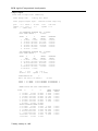
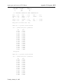
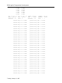
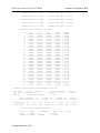
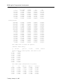
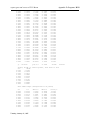
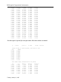
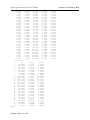
report typos and errors to W.H. Mason
Appendix D: Programs D-19
D.4 LAMDES User’s Manual
This is the Lamar design program, LamDes2.f. It can be used as a non-planar LIDRAG to get
span e for multiple lifting surface cases when user supplies spanload. It has also been called the
Lamar/Mason optimization code. It finds the spanload to minimize the sum of the induced and
pressure drag, including canards or winglets. It also provides the associated camber distribution
for subsonic flow. Since two surfaces are included, it can find the minimum trimmed drag while
satisfying a pitching moment constraint.
The program will prompt you for the input file name. A sample input file called lamdes.inp is on
the disk, and the output obtained from this case is included here.
References:
J.E. Lamar, “A Vortex Latice Method for the Mean Camber Shapes of Trimmed Non-Coplanar
Planforms with Minimum Vortex Drag,” NASA TN D-8090, June, 1976.
W.H. Mason, “Wing-Canard Aerodynamics at Transonic Speeds - Fundamental Considerations
on Minimum Drag Spanloads,” AIAA Paper No. 82-0097, January 1982.
Input Instructions:
The program assumes the load distribution is constant chordwise until a designated chordwise location (XCFW on the first surface and XCFT on the second surface). The loading then decreases
linearly to the trailing edge. This corresponds to a 6 & 6A series camber distribution (the value
for the 6A series is usually 0.8). If airfoil polars are used to model the effects of viscosity, the polars are input in a streamwise coordinate system. The user is responsible for adjusting them from
2D to 3D.
This program uses an input file that is very similar to, but not the same as, the VLMpcv2 code. It
is based on the same geometry and coordinate system ideas. Section D.6 should be consulted for
a discussion of the geometry system.
Card #
Format
1
Literal
2
8F10.6
Tuesday, January 21, 1997
Field
Name
Remarks
DATA
Title card for the data set
1
PLAN
Number of lifting surfaces for the
configuration; use 1 or 2.
2
XMREF
c.g. shift from origin of input planform
coordinate system (the program originally
trimmed the configuration about the input
planform origin).
+ is a c.g. shift forward
- is a c.g. shift aft
3
CREF
reference chord of the configuration,
used only to nondimensionalize the
pitching moment coefficients.
4
SREF
reference area of the configuration
D-20 Applied Computational Aerodynamics
5
TDKLUE
minimization clue
= 0 - minimize induced drag only
= 1 - minimize induced plus pressure drag
6
CASE
options for the drag polar
= 0, model polar, same a, CLmin, CD0
for each surface(see note 3 below).
= 1, model polar, each surface has its
own a, CLmin, CD0
= 2, one general polar for entire config.
= 3, one general polar for each surface
7
SPNKLU
spanload clue
= 0 spanload is internally computed using
the minimization
= 1, no minimization is done, spanload is
read in, and e and pressure drag are
computed.
Geometric/Planform Data - see the VLMpc section (D.6) for more details
Card #
Format
Field
Name
1-P
8F10.6
1
AAN(IT)
# of straight lines defining this surface
2
XS(IT)
= 0. (not used in this code)
3
YS(IT)
= 0. (not used in this code)
4
RTCDHT(IT)
root chord height ( - is “higher”)
5
PDRG1(IT)
CLmin
6
PDRG2(IT)
“a”
7
PDRG3(IT)
CD0
1
XREG
X point of line segment
(positive is forward)
2
YREG
Y point of line segment
(positive is forward)
3
DIH
dihedral angle of line
4
AMCD
sweep wing move code, set = 1 for this
program
2-P
Note:
8F10.6
Remarks
1.
Card 2-P is read in AAN + 1 times. Surface description starts at forward
centerline and works outboard and around, returning to the aft centerline
of the surface.
2.
Cards 1-P and 2-P are read in as a set for each lifting surface
(see VLM4997 for clarification)
3.
The model polar is given by: Cd = a (Cl - Clmin)2 + CD0
Tuesday, January 21, 1997
report typos and errors to W.H. Mason
Appendix D: Programs D-21
Control Data (corresponding to “Group Two” data in Lamar’s nomenclature)
Card #
1-C
2-C
Format
Field
6F5.3,2F10.6 1
6F10.4
Tuesday, January 21, 1997
Name
CONFIG
Remarks
arbitrary configuration number or ID
(may include up to four digits)
2
SCW
Number of chordwise horseshoe vortices
to be used to represent the wing;
a maximum of 20 may be used,
do not set to zero.
3
VIC
nominal number of spanwise rows at
which chordwise horseshoe may be
located; a maximum of 50 may be used.
The product of SCW and SSW cannot
exceed 400 (see VLM4997 chapter for
details of vortex layout).
4
XMCH
Mach number, used to apply PrandtlGlauert comressibility correction factor.
5
CLDES
design lift coefficient for lifting system
6
XITMAX
Maximum number of iterations allowed in
finding the solution for minimum +
pressure drag with arbitrary polars input.
Must be less than 50. 20 is sufficient for
most cases.
7
EPSMAX
The convergence criteria for the general
polar case.A value of .0005 appears to be
reasonable.
1
XCFW
The chord fraction “a” at which the chord
load shape changes from rooftop to a
linear decrease to zero at the trailing edge
on the first planform. See the introduction
to this section for more discussion.
2
XCFT
Same as XCFW, except applies to the
second planform.
3
FKON
Clue for constraints
= 0 body moment constraint
= 1 no constraints
= 2 root bending moment constraint
= 3 both moment anf root bending
moment constraints.
4
CMB
The design wing CM when FKON = 0
5
FICAM
Camber computation clue.
= 0, no cambers computed
= 1, wing cambers computed
D-22 Applied Computational Aerodynamics
3-C
8F10.6
6
PUNCH
clue to punch cambers out
= 0 - no punch file created
= 1 - cards output (unit 7)
7
CRBMT
Design root bending moment
for FKON = 2.
1
RELAX
The under-relaxation factor for the
general polar solution. RELAX = .03 to .3
is satisfactory for most applications.
2
FIOUTW
Output clue.
= 0 - full iteration history is output
= 1 - only final results are output
3
CD0
Basic drag coefficient that will be added to
the drag computed by summing the
induced drag and the profile drag
contained in the input polars.
Arbitrary Polar Input (the following cards are read only if CASE ≥ 2.)
Card #
1-D
Format
Literal
Field
2-D
8F10.5
3-D
8F10.5
Note:
1.
2.
Name
TITLE
Remarks
The identifying title for the input drag
polar for this surface.
1
FNCLCD
The number of CL,CD pairs used to
define the input polar.
1
FQCL
The value of streamwise lift coefficient
for this pooint on the drag polar.
2
FQCD
The value of streamwise drag coefficient
for the given lift coefficient.
Card 3-D is read FNCLCD times
Cards 1-D, 2-D and 3-D are read for each planform if CASE = 3.
Spanload Input (the following cards are read only if SPNKLU = 1)
Card #
1-S
Format
Literal
Field
Name
TITLE
Remarks
This is the title card for the input
spanloads.
2-S
7F10.5
1
FSPNPT
Number of points on the spanload to
be read in for this planform.
3-S
7F10.5
1
YSPNPT
Span location in physical coordinates at
which ccl/ca is input (y is positive here!)
2
CLSPNP
The spanload at YSPNPT
Note:
1.
2.
Card 3-S is read FSPNPT times
Cards 2-S and 3-S are read for each planform as a set.
Tuesday, January 21, 1997
report typos and errors to W.H. Mason
Appendix D: Programs D-23
Sample Input: (note: it is important to put data in proper columns!)
Lamar program sample input - revised forward swept wing
2.000
-8.000
89.50
26640.
1.0
3.0
5.000
0.0
0.0
-8.8
0.0
0.0
68.95
0.0
0.0
1.0
68.95
-34.0
49.61
-65.30
0.0
1.0
25.64
-65.30
0.0
1.0
22.25
-34.00
22.25
0.00
5.0
0.0
0.0
0.0
0.0
0.0
-25.90
0.0
0.0
1.0
-25.90
-34.0
38.10
-164.0
0.0
1.0
-2.40
-164.0
0.0
1.0
-147.90
-20.0
-147.90
0.0
1.0 10.0 20. 0.9 0.90 40.0 0.0006
0.0
0.65
0.0
-0.10
1.0
0.030
1.0
0.0
0.0
0.0
0.0
drag polar on canard (conv. sec)
18.0
0.00
0.0000
0.10
0.0000
0.25
0.0002
0.30
0.00078
0.40
0.00175
0.50
0.00315
0.55
0.0040
0.60
0.00535
0.65
0.00685
0.70
0.00880
0.75
0.01125
0.80
0.01485
0.85
0.01975
0.88
0.02400
0.915
0.03600
1.00
0.0880
1.20
0.2680
1.80
0.9880
drag polar
22.0
0.000
0.0003
0.200
0.0003
0.300
0.0005
0.400
0.0008
0.500
0.00125
0.600
0.00178
0.700
0.00244
0.800
0.00324
0.900
0.00442
0.950
0.00528
0.970
0.00570
0.990
0.00621
1.000
0.00650
1.020
0.00730
1.040
0.00820
1.060
0.00930
1.080
0.01090
1.100
0.01280
1.125
0.02400
1.130
0.03600
1.200
0.20400
2.000
2.12400
Tuesday, January 21, 1997
0.0
D-24 Applied Computational Aerodynamics
Sample Output:
enter name of input file: lamdes.inp
Lamar Design Code
mods by W.H. Mason
Lamar program sample input - revised forward swept wing
plan
= 2.0 xmref =
tdklue = 1.0 case =
sref
=
26640.0000
-8.0000
3.0
cref
= 89.5000
spnklu = 0.0
1st REFERENCE PLANFORM HAS 5 CURVES
ROOT CHORD HEIGHT =
-8.8000
POINT
1
2
3
4
5
6
X
REF
76.9500
76.9500
57.6100
33.6400
30.2500
30.2500
Y
REF
0.0000
-34.0000
-65.3000
-65.3000
-34.0000
0.0000
SWEEP
ANGLE
0.00000
31.71155
90.00000
-6.18142
0.00000
DIHEDRAL
ANGLE
0.00000
0.00000
0.00000
0.00000
0.00000
2nd REFERENCE PLANFORM HAS 5 CURVES
ROOT CHORD HEIGHT =
0.0000
POINT
X
Y
SWEEP
REF
REF
ANGLE
1 -17.9000
0.0000
0.00000
2 -17.9000 -34.0000 -26.21138
3 46.1000-164.0000 90.00000
4
5.6000-164.0000 -45.29687
5-139.9000 -20.0000
0.00000
6-139.9000
0.0000
scw
= 10.0
xitmax = 40.0
vic = 20.0
epsmax = 0.00060
CONFIGURATION NO.
1.
delta ord shift for moment =
CURVE
CURVE
DIHEDRAL
ANGLE
0.00000
0.00000
0.00000
0.00000
0.00000
1 IS SWEPT
1 IS SWEPT
-8.0000
0.0000 DEGREES ON PLANFORM
0.0000 DEGREES ON PLANFORM
1
2
BREAK POINTS FOR THIS CONFIGURATION
POINT
X
Y
Z
SWEEP
ANGLE
0.0000
0.0000
31.7116
90.0000
-6.1814
0.0000
1 76.9500
0.0000 -8.8000
2 76.9500 -20.0000 -8.8000
3 76.9500 -34.0000 -8.8000
4 57.6100 -65.3000 -8.8000
5 33.6400 -65.3000 -8.8000
6 30.2500 -34.0000 -8.8000
7 30.2500
0.0000 -8.8000
SECOND PLANFORM BREAK POINTS
1 -17.9000
0.0000
0.0000
0.0000
2 -17.9000 -34.0000
0.0000 -26.2114
3 -2.4908 -65.3000
0.0000 -26.2114
4 46.1000-164.0000
0.0000 90.0000
5
5.6000-164.0000
0.0000 -45.2969
6-139.9000 -20.0000
0.0000
0.0000
7-139.9000
0.0000
0.0000
Tuesday, January 21, 1997
DIHEDRAL
ANGLE
0.0000
0.0000
0.0000
0.0000
0.0000
0.0000
0.0000
0.0000
0.0000
0.0000
0.0000
0.0000
report typos and errors to W.H. Mason
Appendix D: Programs D-25
280 HORSESHOE VORTICES USED
PLANFORM
TOTAL
SPANWISE
1
80
8
2
200
20
10. HORSESHOE VORTICES IN EACH CHORDWISE ROW
xcfw = 0.00
ficam = 1.00
cmb
= -.10
xcft
punch
iflag
=
=
=
relax = 0.03
firbm = 0.00
fioutw =
yrbm
=
0.65
0.00
1
fkon
=
crbmnt =
0.00
0.000
1.00
0.0000
cd0
zrbm
0.0000
0.0000
drag polar on canard (conv. sec)
there are
18.0
1.0 polars on this surface
points this polar
qcl
0.0000
0.1000
0.2500
0.3000
0.4000
0.5000
0.5500
0.6000
0.6500
0.7000
0.7500
0.8000
0.8500
0.8800
0.9150
1.0000
1.2000
1.8000
planform 1
qcd
0.0000
0.0000
0.0002
0.0008
0.0018
0.0032
0.0040
0.0054
0.0069
0.0088
0.0113
0.0148
0.0198
0.0240
0.0360
0.0880
0.2680
0.9880
drag polar
there are
22.0
1.0 polars on this surface
points this polar
qcl
0.0000
0.2000
0.3000
0.4000
0.5000
0.6000
0.7000
0.8000
0.9000
0.9500
0.9700
0.9900
1.0000
1.0200
1.0400
Tuesday, January 21, 1997
qcd
0.0003
0.0003
0.0005
0.0008
0.0012
0.0018
0.0024
0.0032
0.0044
0.0053
0.0057
0.0062
0.0065
0.0073
0.0082
planform 2
=
=
D-26 Applied Computational Aerodynamics
1.0600
1.0800
1.1000
1.1250
1.1300
1.2000
2.0000
LM = 70 IL = 71
BOTL = 164.000
NMA(KBOT) = 50
0.0093
0.0109
0.0128
0.0240
0.0360
0.2040
2.1240
JM = 72 IM = 73
BOL = 65.300
KBOT = 2
TSPAN =-164.000
SNN
= 1.6400
NMA(KBIT) = 20
TSPANA = -65.300
DELTYB = 3.2800
KBIT
= 1
induced drag cd = 0.06815
pressure drag cdpt = 0.01665
induced drag cd = 0.06818
pressure drag cdpt = 0.01441
induced drag cd = 0.06827
pressure drag cdpt = 0.01255
induced drag cd = 0.06839
pressure drag cdpt = 0.01139
induced drag cd = 0.06850
pressure drag cdpt = 0.01053
induced drag cd = 0.06863
pressure drag cdpt = 0.00976
induced drag cd = 0.06876
pressure drag cdpt = 0.00915
induced drag cd = 0.06885
pressure drag cdpt = 0.00886
induced drag cd = 0.06893
pressure drag cdpt = 0.00868
induced drag cd = 0.06898
pressure drag cdpt = 0.00856
induced drag cd = 0.06902
pressure drag cdpt = 0.00847
induced drag cd = 0.06905
pressure drag cdpt = 0.00841
induced drag cd = 0.06907
pressure drag cdpt = 0.00836
induced drag cd = 0.06909
pressure drag cdpt = 0.00832
induced drag cd = 0.06911
pressure drag cdpt = 0.00829
induced drag cd = 0.06913
pressure drag cdpt = 0.00826
induced drag cd = 0.06915
pressure drag cdpt = 0.00823
induced drag cd = 0.06916
pressure drag cdpt = 0.00821
induced drag cd = 0.06917
pressure drag cdpt = 0.00819
induced drag cd = 0.06918
pressure drag cdpt = 0.00817
induced drag cd = 0.06919
pressure drag cdpt = 0.00816
induced drag cd = 0.06920
pressure drag cdpt = 0.00815
induced drag cd = 0.06921
pressure drag cdpt = 0.00814
induced drag cd = 0.06921
pressure drag cdpt = 0.00813
induced drag cd = 0.06922
pressure drag cdpt = 0.00812
induced drag cd = 0.06923
pressure drag cdpt = 0.00811
Tuesday, January 21, 1997
report typos and errors to W.H. Mason
Appendix D: Programs D-27
induced drag cd = 0.06923
pressure drag cdpt = 0.00810
induced drag cd = 0.06924
pressure drag cdpt = 0.00810
induced drag cd = 0.06924
pressure drag cdpt = 0.00809
induced drag cd = 0.06924
pressure drag cdpt = 0.00809
induced drag cd = 0.06925
pressure drag cdpt = 0.00808
pressure drag iteration has converged
k
1
2
3
4
5
6
7
8
9
10
11
12
13
14
15
16
17
18
19
20
21
22
23
24
25
26
27
28
29
30
31
eps
28.66362
0.05789
0.05278
0.04274
0.03408
0.03155
0.02773
0.02043
0.01549
0.01218
0.00994
0.00847
0.00724
0.00616
0.00519
0.00442
0.00371
0.00310
0.00263
0.00221
0.00183
0.00154
0.00131
0.00112
0.00095
0.00084
0.00076
0.00069
0.00064
0.00061
0.00057
cl
0.90000
0.90000
0.90000
0.90000
0.90000
0.90000
0.90000
0.90000
0.90000
0.90000
0.90000
0.90000
0.90000
0.90000
0.90000
0.90000
0.90000
0.90000
0.90000
0.90000
0.90000
0.90000
0.90000
0.90000
0.90000
0.90000
0.90000
0.90000
0.90000
0.90000
0.90000
cdi
0.06815
0.06818
0.06827
0.06839
0.06850
0.06863
0.06876
0.06885
0.06893
0.06898
0.06902
0.06905
0.06907
0.06909
0.06911
0.06913
0.06915
0.06916
0.06917
0.06918
0.06919
0.06920
0.06921
0.06921
0.06922
0.06923
0.06923
0.06924
0.06924
0.06924
0.06925
cdp
0.01665
0.01441
0.01255
0.01139
0.01053
0.00976
0.00915
0.00886
0.00868
0.00856
0.00847
0.00841
0.00836
0.00832
0.00829
0.00826
0.00823
0.00821
0.00819
0.00817
0.00816
0.00815
0.00814
0.00813
0.00812
0.00811
0.00810
0.00810
0.00809
0.00809
0.00808
cdi+cdp
0.08480
0.08260
0.08082
0.07978
0.07903
0.07839
0.07791
0.07772
0.07761
0.07754
0.07749
0.07746
0.07743
0.07741
0.07740
0.07739
0.07738
0.07737
0.07736
0.07736
0.07735
0.07735
0.07734
0.07734
0.07734
0.07734
0.07733
0.07733
0.07733
0.07733
0.07733
induced + pressure drag was minimized on this run
ref. chord =
89.500
ref. area = 26640.000
true ar
=
3.2828
first planform
second planform
c average
=
b/2
=
Mach number =
1st planform
2nd planform
cl =
cl =
CL = 0.1713
CL = 0.7292
81.2195
164.0000
0.9000
0.17126
0.72874
cm =
cm =
CDP = 0.0042
CDP = 0.0038
true area =
ref ar
=
0.11493
-0.21493
CM = 0.1150
CM = -0.2149
cb =
cb =
32771.566
4.0384
-0.01502
-0.18341
CB = -0.0151
CB = 0.0000
no root bending moment constraint
CL DES = 0.90000
CD I
= 0.06925
CDPRESS = 0.00804
Tuesday, January 21, 1997
CL COMPUTED =
E
=
CDTOTAL
=
0.9005
0.9230
0.07729
CM = -0.0999
D-28 Applied Computational Aerodynamics
first planform
Y
-61.2000
-53.0000
-44.8000
-37.3500
-29.9000
-22.9000
-15.9000
-5.9000
CL*C/CAVE
0.21189
0.33566
0.41311
0.46740
0.49499
0.50260
0.50504
0.50631
C/CAVE
0.33178
0.40510
0.47842
0.54503
0.57498
0.57498
0.57498
0.57498
CL
0.63862
0.82857
0.86348
0.85757
0.86088
0.87411
0.87835
0.88056
CD
0.00651
0.01765
0.02166
0.02082
0.02129
0.02317
0.02377
0.02419
0.33879
0.53136
0.64513
0.72403
0.78509
0.83563
0.87760
0.91055
0.93428
0.94681
0.94347
0.90911
0.82859
0.74419
0.67721
0.63142
0.60043
0.58289
0.57323
0.56730
0.52480
0.57711
0.62942
0.68173
0.73404
0.78635
0.83866
0.89096
0.94327
0.99558
1.04789
1.10116
1.15442
1.20673
1.25904
1.30656
1.37894
1.46602
1.50210
1.50210
0.64556
0.92072
1.02495
1.06206
1.06954
1.06267
1.04644
1.02198
0.99047
0.95101
0.90036
0.82559
0.71775
0.61670
0.53788
0.48327
0.43543
0.39760
0.38162
0.37767
0.00208
0.00478
0.00752
0.00946
0.01006
0.00951
0.00855
0.00739
0.00622
0.00530
0.00443
0.00354
0.00258
0.00189
0.00145
0.00117
0.00096
0.00079
0.00074
0.00073
second planform
-159.9000
-151.7000
-143.5000
-135.3000
-127.1000
-118.9000
-110.7000
-102.5000
-94.3000
-86.1000
-77.9000
-69.5500
-61.2000
-53.0000
-44.8000
-37.3500
-29.9000
-22.9000
-15.9000
-5.9000
mean camber lines to obtain the spanload
(subsonic linear theory)
y=
-61.2000
slopes,
x/c
0.0750
0.1750
0.2750
0.3750
0.4750
0.5750
0.6750
0.7750
0.8750
0.9750
y/(b/2) =
-0.3732
chord=
dz/dx, at control points, from front to rear
dz/dx
0.1295
0.0672
0.0194
-0.0200
-0.0522
-0.0775
-0.0960
-0.1077
-0.1122
-0.1081
mean camber shape (interpolated to 41 points)
x/c
0.0000
0.0250
0.0500
0.0750
0.1000
0.1250
0.1500
26.9474
z/c
-0.0299
-0.0332
-0.0365
-0.0398
-0.0429
-0.0457
-0.0480
Tuesday, January 21, 1997
delta x
0.0000
0.6737
1.3474
2.0211
2.6947
3.3684
4.0421
delta z
-0.8067
-0.8944
-0.9831
-1.0717
-1.1558
-1.2310
-1.2945
(z-zle)/c
0.0000
-0.0040
-0.0080
-0.0121
-0.0159
-0.0195
-0.0226
report typos and errors to W.H. Mason
0.1750
0.2000
0.2250
0.2500
0.2750
0.3000
0.3250
0.3500
0.3750
0.4000
0.4250
0.4500
0.4750
0.5000
0.5250
0.5500
0.5750
0.6000
0.6250
0.6500
0.6750
0.7000
0.7250
0.7500
0.7750
0.8000
0.8250
0.8500
0.8750
0.9000
0.9250
0.9500
0.9750
1.0000
y=
-0.0499
-0.0514
-0.0526
-0.0534
-0.0540
-0.0544
-0.0545
-0.0544
-0.0540
-0.0534
-0.0525
-0.0515
-0.0503
-0.0489
-0.0474
-0.0456
-0.0438
-0.0418
-0.0396
-0.0374
-0.0350
-0.0326
-0.0301
-0.0275
-0.0248
-0.0221
-0.0193
-0.0165
-0.0137
-0.0109
-0.0081
-0.0054
-0.0027
0.0000
-53.0000
slopes,
x/c
0.0750
0.1750
0.2750
0.3750
0.4750
0.5750
0.6750
0.7750
0.8750
0.9750
Appendix D: Programs D-29
4.7158
5.3895
6.0632
6.7368
7.4105
8.0842
8.7579
9.4316
10.1053
10.7790
11.4526
12.1263
12.8000
13.4737
14.1474
14.8211
15.4948
16.1684
16.8421
17.5158
18.1895
18.8632
19.5369
20.2105
20.8842
21.5579
22.2316
22.9053
23.5790
24.2527
24.9263
25.6000
26.2737
26.9474
-1.3456
-1.3857
-1.4166
-1.4399
-1.4563
-1.4660
-1.4689
-1.4651
-1.4548
-1.4383
-1.4160
-1.3884
-1.3556
-1.3181
-1.2760
-1.2297
-1.1794
-1.1254
-1.0679
-1.0074
-0.9440
-0.8781
-0.8100
-0.7400
-0.6682
-0.5950
-0.5205
-0.4452
-0.3696
-0.2942
-0.2196
-0.1458
-0.0728
0.0000
y/(b/2) =
-0.3232
-0.0252
-0.0275
-0.0294
-0.0310
-0.0323
-0.0334
-0.0343
-0.0349
-0.0353
-0.0354
-0.0353
-0.0351
-0.0346
-0.0339
-0.0331
-0.0322
-0.0310
-0.0298
-0.0284
-0.0269
-0.0253
-0.0236
-0.0218
-0.0200
-0.0181
-0.0161
-0.0141
-0.0120
-0.0100
-0.0079
-0.0059
-0.0039
-0.0020
0.0000
chord=
dz/dx, at control points, from front to rear
dz/dx
0.0783
-0.0034
-0.0572
-0.0982
-0.1306
-0.1557
-0.1740
-0.1854
-0.1898
-0.1845
mean camber shape (interpolated to 41 points)
x/c
0.0000
0.0250
0.0500
0.0750
0.1000
0.1250
0.1500
0.1750
0.2000
0.2250
0.2500
32.9022
z/c
-0.1036
-0.1056
-0.1076
-0.1097
-0.1115
-0.1128
-0.1136
-0.1138
-0.1135
-0.1128
-0.1117
Tuesday, January 21, 1997
delta x
0.0000
0.8226
1.6451
2.4677
3.2902
4.1128
4.9353
5.7579
6.5804
7.4030
8.2256
delta z
-3.4093
-3.4745
-3.5414
-3.6080
-3.6674
-3.7122
-3.7381
-3.7444
-3.7339
-3.7102
-3.6761
(z-zle)/c
0.0000
-0.0046
-0.0092
-0.0138
-0.0182
-0.0222
-0.0255
-0.0283
-0.0306
-0.0325
-0.0340
D-30 Applied Computational Aerodynamics
0.2750
0.3000
0.3250
0.3500
0.3750
0.4000
0.4250
0.4500
0.4750
0.5000
0.5250
0.5500
0.5750
0.6000
0.6250
0.6500
0.6750
0.7000
0.7250
0.7500
0.7750
0.8000
0.8250
0.8500
0.8750
0.9000
0.9250
0.9500
0.9750
1.0000
-0.1104
-0.1089
-0.1070
-0.1050
-0.1026
-0.1001
-0.0973
-0.0943
-0.0911
-0.0878
-0.0842
-0.0806
-0.0767
-0.0728
-0.0687
-0.0645
-0.0602
-0.0558
-0.0513
-0.0468
-0.0422
-0.0375
-0.0328
-0.0281
-0.0233
-0.0186
-0.0139
-0.0092
-0.0046
0.0000
9.0481
9.8707
10.6932
11.5158
12.3383
13.1609
13.9834
14.8060
15.6285
16.4511
17.2737
18.0962
18.9188
19.7413
20.5639
21.3864
22.2090
23.0315
23.8541
24.6766
25.4992
26.3218
27.1443
27.9669
28.7894
29.6120
30.4345
31.2571
32.0796
32.9022
-3.6333
-3.5819
-3.5220
-3.4534
-3.3766
-3.2920
-3.2003
-3.1020
-2.9975
-2.8872
-2.7715
-2.6505
-2.5247
-2.3945
-2.2601
-2.1219
-1.9804
-1.8358
-1.6886
-1.5391
-1.3875
-1.2341
-1.0792
-0.9233
-0.7671
-0.6114
-0.4569
-0.3038
-0.1517
0.0000
-0.0353
-0.0363
-0.0371
-0.0376
-0.0379
-0.0379
-0.0377
-0.0373
-0.0367
-0.0359
-0.0350
-0.0339
-0.0327
-0.0313
-0.0298
-0.0282
-0.0265
-0.0247
-0.0228
-0.0209
-0.0189
-0.0168
-0.0147
-0.0125
-0.0104
-0.0082
-0.0061
-0.0041
-0.0020
0.0000
Note this output is repeated for each span station. Most other stations are omitted
y=
-5.9000
slopes,
x/c
0.0750
0.1750
0.2750
0.3750
0.4750
0.5750
0.6750
0.7750
0.8750
0.9750
y/(b/2) =
-0.0360
chord=
dz/dx, at control points, from front to rear
dz/dx
-0.0501
-0.0505
-0.0495
-0.0500
-0.0537
-0.0623
-0.0814
-0.0975
-0.1077
-0.1097
mean camber shape (interpolated to 41 points)
x/c
0.0000
0.0250
0.0500
0.0750
0.1000
0.1250
0.1500
0.1750
0.2000
122.0000
z/c
-0.0697
-0.0685
-0.0672
-0.0660
-0.0647
-0.0635
-0.0622
-0.0609
-0.0597
Tuesday, January 21, 1997
delta x
0.0000
3.0500
6.1000
9.1500
12.2000
15.2500
18.3000
21.3500
24.4000
delta z
-8.5090
-8.3562
-8.2034
-8.0506
-7.8975
-7.7440
-7.5900
-7.4358
-7.2818
(z-zle)/c
0.0000
-0.0005
-0.0010
-0.0015
-0.0020
-0.0024
-0.0029
-0.0034
-0.0039
report typos and errors to W.H. Mason
0.2250
0.2500
0.2750
0.3000
0.3250
0.3500
0.3750
0.4000
0.4250
0.4500
0.4750
0.5000
0.5250
0.5500
0.5750
0.6000
0.6250
0.6500
0.6750
0.7000
0.7250
0.7500
0.7750
0.8000
0.8250
0.8500
0.8750
0.9000
0.9250
0.9500
0.9750
1.0000
-0.0584
-0.0572
-0.0559
-0.0547
-0.0535
-0.0522
-0.0510
-0.0497
-0.0485
-0.0472
-0.0458
-0.0445
-0.0431
-0.0416
-0.0401
-0.0385
-0.0368
-0.0349
-0.0330
-0.0309
-0.0287
-0.0264
-0.0240
-0.0215
-0.0189
-0.0163
-0.0137
-0.0110
-0.0082
-0.0055
-0.0027
0.0000
27.4500
30.5000
33.5500
36.6000
39.6500
42.7000
45.7500
48.8000
51.8500
54.9000
57.9500
61.0000
64.0500
67.1000
70.1500
73.2000
76.2500
79.3000
82.3500
85.4000
88.4500
91.5000
94.5500
97.6000
100.6500
103.7000
106.7500
109.8000
112.8500
115.9000
118.9500
122.0000
Appendix D: Programs D-31
-7.1286
-6.9763
-6.8249
-6.6742
-6.5237
-6.3728
-6.2210
-6.0676
-5.9121
-5.7537
-5.5919
-5.4262
-5.2558
-5.0791
-4.8940
-4.6978
-4.4878
-4.2627
-4.0221
-3.7669
-3.4982
-3.2174
-2.9253
-2.6231
-2.3115
-1.9920
-1.6662
-1.3359
-1.0031
-0.6690
-0.3345
0.0000
twist table
i
1
2
3
4
5
6
7
8
9
10
11
12
13
14
15
16
17
18
19
20
21
22
23
24
25
26
27
28
y
-61.20000
-53.00000
-44.80000
-37.35000
-29.90000
-22.90000
-15.90000
-5.90000
-159.89999
-151.70001
-143.50000
-135.30002
-127.10001
-118.90002
-110.70002
-102.50002
-94.30003
-86.10003
-77.90003
-69.55002
-61.20000
-53.00000
-44.80000
-37.35000
-29.90000
-22.90000
-15.90000
-5.90000
y/(b/2)
-0.37317
-0.32317
-0.27317
-0.22774
-0.18232
-0.13963
-0.09695
-0.03598
-0.97500
-0.92500
-0.87500
-0.82500
-0.77500
-0.72500
-0.67500
-0.62500
-0.57500
-0.52500
-0.47500
-0.42409
-0.37317
-0.32317
-0.27317
-0.22774
-0.18232
-0.13963
-0.09695
-0.03598
STOP
Tuesday, January 21, 1997
twist
1.71469
5.91587
7.36720
10.25835
9.47910
7.60813
6.49868
5.91663
14.45816
16.44655
14.38027
12.36750
10.75520
9.51973
8.46040
7.34168
6.13154
4.67249
2.88238
1.36595
3.52797
4.51491
4.49845
3.79378
3.77474
3.11226
3.52109
3.98970
-0.0044
-0.0049
-0.0054
-0.0059
-0.0064
-0.0069
-0.0074
-0.0079
-0.0084
-0.0088
-0.0092
-0.0096
-0.0100
-0.0102
-0.0105
-0.0106
-0.0106
-0.0105
-0.0103
-0.0100
-0.0095
-0.0089
-0.0083
-0.0076
-0.0067
-0.0059
-0.0049
-0.0040
-0.0030
-0.0020
-0.0010
0.0000