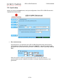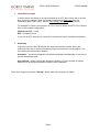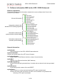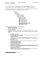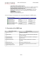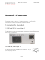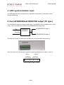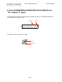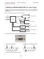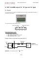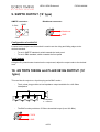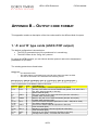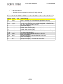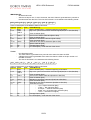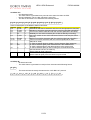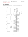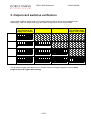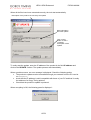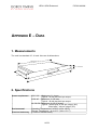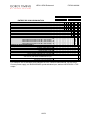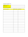
1
LEDI 1/S/RK Enhanced USER MANUAL LEDI 1/S/RK Enhanced FOR19/A/466N CONTENTS 1 1 CONTENTS...........................................................................................................................1 2 INTRODUCTION...................................................................................................................3 1. QUICK INSTALLATION ..........................................................................................................4 2. SET-UP YOUR PRODUCT ......................................................................................................5 2.1. Manual network configuration ....................................................................................5 2.2. Output card configuration...........................................................................................5 3 FULL SETUP ........................................................................................................................7 1. NETWORK CONFIGURATION .................................................................................................7 1.1. Default configuration ..................................................................................................7 1.2. Changing network parameters ...................................................................................8 1.3. Integration in your network.........................................................................................9 2. OUTPUT CARD CONFIGURATION.........................................................................................10 2.1. Introduction ..............................................................................................................10 2.2. Default configuration ................................................................................................10 2.3. Change the settings .................................................................................................10 4 FRONT DISPLAY INTERFACE..........................................................................................11 1. START-UP CONDITIONS .....................................................................................................11 2. TIME DISPLAY ...................................................................................................................12 3. MINOR ALARM CONDITIONS ...............................................................................................13 4. MAJOR ALARM CONDITIONS ...............................................................................................13 5 WEB INTERFACE ..............................................................................................................15 1. PRESENTATION ................................................................................................................15 2. DESCRIPTION OF THE WEB INTERFACE .............................................................................16 2.1. Main screen..............................................................................................................16 2.2. Standard setup.........................................................................................................17 2.3. SNMP setup .............................................................................................................20 2.4. Output and display setup .........................................................................................22 2.5. Input setup ...............................................................................................................27 6 SNMP INTERFACE ............................................................................................................30 1. PRESENTATION ................................................................................................................30 1.1. Software information MIB for the LEDI 1/S/RK Enhanced .......................................31 1.2. Hardware information MIB for the LEDI 1/S/RK Enhanced......................................34 1.3. Description of the SNMP traps.................................................................................35 1/79 LEDI 1/S/RK Enhanced FOR19/A/466N 7 APPENDIX A – CONNECTIONS........................................................................................38 1. CONNECTION FOR ALL PRODUCTS .....................................................................................38 1.1. 230V and 115V AC product (type ‘0’).......................................................................38 1.2. 18/72V DC product (type ‘9’)....................................................................................38 2. AFNOR NFS87500 / IRIG-B SINE WAVE / TDF / DCF SYNCHRONIZATION INPUT ...............39 3. AFNOR NFS87500/ IRIG-B DCLS SYNCHRONIZATION INPUT...........................................39 4. GPS SYNCHRONIZATION INPUT .........................................................................................40 5. DUAL AFNOR/IRIG-B NFS87500 OUTPUT (‘B’ TYPE) .......................................................40 6. DUAL AFNOR/IRIG-B NFS87500 DCLS RS422 AND TTL OUTPUT (‘T’ TYPE) ..................41 7. RS232 AND 485/422 ASCII+TOP (‘A’ AND ‘R’ TYPE)........................................................42 8. TOP / ALARM OUTPUT (‘A’, ‘R’ TYPE AND ‘G’ TYPE) .........................................................43 8.1. Pin-out......................................................................................................................43 9. SMPTE OUTPUT (‘S’ TYPE)............................................................................................44 10. 4/6 TOPS 1000HZ AND FLAIX 861HZ OUTPUT (‘H’ TYPE)............................................44 11. 10MHZ TTL OUTPUT (GPS SYNCHRONIZATION AND OCXO ONLY)................................45 8 APPENDIX B – OUTPUT CODE FORMAT........................................................................46 1. ‘A’ AND ‘R’ TYPE CARDS (ASCII+TOP OUTPUT).................................................................46 2. ‘B’ AND ‘T’ TYPE CARDS (AFNOR/IRIG-B NFS87500) ......................................................53 2.1. Frame format............................................................................................................53 2.2. Bit encoding .............................................................................................................54 3. DCF AND TDF TIME CODE DESCRIPTION ...........................................................................55 4. SMPTE MESSAGE DESCRIPTION .......................................................................................56 9 APPENDIX C – TROUBLESHOOTING..............................................................................58 10 APPENDIX D – MAINTENANCE......................................................................................62 1. PROCEDURE TO FOLLOW TO CHANGE THE BATTERY ...........................................................62 2. OUTPUT CARD SWITCHES VERIFICATION ............................................................................63 3. UPDATING FIRMWARE .......................................................................................................64 3.1. Obtaining Firmware..................................................................................................64 3.2. Reloading Firmware .................................................................................................64 11 APPENDIX E – DATA.......................................................................................................66 1. MEASUREMENTS ..............................................................................................................66 2. SPECIFICATIONS ...............................................................................................................66 3. STAMP CONTENTS ............................................................................................................67 12 APPENDIX F – ADDITIONAL DOCUMENTS ..................................................................70 2/79 LEDI 1/S/RK Enhanced FOR19/A/466N INTRODUCTION 2 This document is a user’s guide for the LEDI 1/S/RK Enhanced. This device can be synchronized either by GPS, either by AFNOR NFS87500, or TDF / DCF radio signal. Optional synchronization outputs are available (alarm, ASCII+TOP, AFNOR NFS87500, IRIG-B, SMPTE, 1000HZ TOPS) Using the LEDI 1/S/RK Enhanced provides you with several advantages: • You can use the installed network architecture with the well-known protocols Ethernet+TCP/IP; • Simplified set-up; • Easy remote configuration and diagnostic; • The product is a 19” 1U rack that can be easily installed on your installation; • It provides configurable synchronization outputs. By using Gorgy Timing clients in combination with the LEDI 1/S/RK Enhanced you greatly improve the ease of installation and use. * Jump directly to section 1 page 4 for quick installation 3/79 LEDI 1/S/RK Enhanced FOR19/A/466N 1. Quick installation This part contains the minimum information for the set-up of the LEDI 1/S/RK Enhanced. You can found additional information in part 3. Check the package content The package must contains the following items: n The product itself: a 19” 1U rack. • • * The name of this product is LEDI 1/S/RK ENHANCED which is written on the front side of the rack; The code and configuration of the product can be checked on the identification stamp put on top or backside of the product. It must be 9213/opt (where opt depends on the output cards – see Appendix E – Data - Stamp contents). o A power supply cable (only for 220V AC and 115V AC versions); p A network cable; q A CDROM that contains set-up and management tools. Contact your dealer if one of the items above isn’t in the package Connect the product n It is highly recommended that you notice the serial number (written on identification stamp), the localization and a short description for the product. The table in You can use the table in Appendix F – Additional documents o Connect the synchronization outputs to your equipment (see Appendix A – Connections for more information); p Connect the LEDI 1/S/RK Enhanced to your network using the network cable; q Connect the LEDI 1/S/RK Enhanced to a power supply using the power supply cable when it is present. Your system should work immediately if there is a DHCP server on your network. After a few seconds, the LEDI 1/S/RK Enhanced activates its outputs. However, Gorgy Timing recommends you to fill-in for each product its physical localization. This is possible using the GTNetMng tool localized on the CD-ROM. For more information, see part 1.2. 4/79 LEDI 1/S/RK Enhanced FOR19/A/466N 2. Set-up your product 2.1. Manual network configuration Gorgy Timing Network products are configured in factory to automatically get an IP address. Two mechanisms are used: 1. If a DHCP server is present on your network, our products get an address automatically. This ensures that the IP address is compatible with your network; 2. If no DHCP server is present, the product automatically takes an IP address using the AutoIP mechanism. In this case, the address is in the range 169.254.x.y (where x and y are in the 0..255 range). If both server and client have started in this mode, they should work correctly together but their IP addresses may be incompatible with other devices on the network.1 The default DHCP identifier is LEnnnnnn (nnnnnn is the serial number of the product).2 You can change this identifier with the GTNetMng tool or through the WEB interface as described in part 1.2 and 2.2. If you don’t have a DHCP server or you want to configure yourself the network parameters, use the GTNetMng tool on the CDROM to change the network parameter. Please refer to part 1.2 for more information. * Don’t hesitate to contact your network administrator for the configuration of the LEDI 1/S/RK Enhanced. He can help you to optimize your network installation 2.2. Output card configuration The default configuration for all the output cards is to deliver UTC time. The time received from the synchronization input is directly sent to the output in UTC format. Each card can be configured to output several local times. This configuration is done through a WEB browser (see part 2). 1 For example, you may not have the possibility to configure the LEDI 1/S/RK Enhanced from a WEB navigator. 2 Some DHCP servers have the ability to copy the DHCP name into the DNS. In this case, you can access the LEDI 1/S/RK Enhanced directly by its DHCP name instead of its IP address. 5/79 LEDI 1/S/RK Enhanced 6/79 FOR19/A/466N LEDI 1/S/RK Enhanced FOR19/A/466N FULL SETUP 3 This part contains information for a full configuration of the product. It should be used for fine network configuration and output cards set-up. 1. Network configuration 1.1. Default configuration The LEDI 1/S/RK Enhanced is configured to automatically take an IP address from a DHCP server. At startup, the product broadcast a DHCP query to get an IP address. This query contains a DHCP name. There are two cases: • If a DHCP server is installed on the network, it record the DHCP name and return an IP address. The LEDI 1/S/RK Enhanced starts working with this address; • If no DHCP server is installed, the LEDI 1/S/RK Enhanced automatically use a default IP address in the range 169.254.x.y (where x and y are between 0 and 255). The default DHCP identifier of the product is LEnnnnnn with nnnnnn, the serial number on 6 digits. The serial number is written on the identification stamp on the top or on the bottom of the product. The default SNMP name of the product (that can be seen from a SNMP browser (see part 6) or from a WEB browser) is LediNetEnhnnnnnn with nnnnnn, the serial number on 6 digits. 7/79 LEDI 1/S/RK Enhanced FOR19/A/466N 1.2. Changing network parameters Use the GTNetMng tool provided on the CDROM to configure your device: n Insert the CDROM in the drive. Start the GTNetMng tool that is localized in the directory Common\Configuration3 o The GTNetMng tool displays automatically the Gorgy Timing products installed on your network. Each line contains information about one connected product as shown below: Name, serial number and localization p Current IP address network mask MAC address DHCP identifier Double-click on the line related to the product you want to configure. The following panel is displayed: Name of the device (GT LEDI 1/S/RK Enhanced) -- Serial number (040204) Localization (Test Line) Ethernet (MAC) address of the Localization of the product q Set the network parameters and physical localization and click the Set! button. 3 For example, if your CD reader has letter E:, the GTNetMng tool is localized in E:\Common\Configuration\GTNetMng.exe 8/79 LEDI 1/S/RK Enhanced FOR19/A/466N 1.3. Integration in your network You don’t have to change any network setting for the following cases: • You have a DHCP server and enough reserved IP address for the product; • You don’t have a DHCP server but you don’t need to access to the device through its WEB or SNMP interface. In this case, the AutoIP mechanism will automatically affect an IP address but this address will probably be incompatible with your network. Anyway if several devices work with AutoIP, they could works together. Some DHCP servers have the capacity to register the device in the DNS. In this case, the registered name is the DHCP identifier. Then, you can access to the device from your WEB or SNMP browser. For example if you give the DHCP name ntpsrv1 to your LEDI 1/S/RK Enhanced, you can simply type ntpsrv1 in the address field of your WEB browser. If you have several products to install on your installation, it is highly recommended to follow the following steps: • Use the document provided in Appendix F – Additional documents (Summarized installation view) and note the serial number and physical localization of each product during the installation and connection; • On a PC connected on the same network that the products and start GTNetMng. All the GT products should appear with their serial number. Set the network parameter and localization using the document filled at previous step. • You can keep this document for further reference. You can found the summarized installation view document in a WORD format on the CD-ROM. Its full path is English\LEDI 1/S/RK Enhanced\docs\installation.doc. 9/79 LEDI 1/S/RK Enhanced FOR19/A/466N 2. Output card configuration 2.1. Introduction Your LEDI 1/S/RK Enhanced is provided with up to 4 output cards. Each card acts as a kind of translator that receives time from the synchronization input and generates specific time code. Currently, there are 7 kinds of cards: • ASCII+TOP RS232 (‘A’ type card) ; • ASCII+TOP RS485 (‘R’ type card) ; • AFNOR NFS 87500 / IRIGB (‘B’ type card) ; • AFNOR /IRIGB TTL / RS422 (‘T’ type card) ; • ALARM (‘G’ type card) ; • SMPTE/EBU (‘S’ type card). • 4/6 TOPS 1000Hz (‘H’ type card). You can freely use and copy the table Devices configuration in Appendix F – Additional documents. 2.2. Default configuration When you receive this product from Gorgy Timing, all the output cards are configured to output UTC time and time is constant all along the year (no Day Saving Time correction). The display is managed as an output cards and can be configured in the same way. 2.3. Change the settings Open the WEB site of the LEDI 1/S/RK Enhanced (see part 5). Click on the button. The current configuration of your product appears at the screen: In this screen you can tune each card independently (see page 22). When you have changed the settings, click on the the outputs or on the display. button. The modification should appear immediately at 10/79 LEDI 1/S/RK Enhanced FOR19/A/466N FRONT DISPLAY INTERFACE 4 The front display interface can display up to 16 characters. Two buttons provides you with display configuration and global reset. The LEDI 1/S/RK Enhanced uses the front display to show current time and different alarm condition. Reset the LEDI 1/S/RK Enhanced Switch between UTC and LOCAL time display 1. Start-up conditions During start-up, the time and date of the LEDI 1/S/RK Enhanced are not valid and are not displayed. Then, you can see the following texts: • When the device start, all the dots of the displays are lightened; • During hardware initialization, the following text is displayed: • Then, the IP address of the product appears; 11/79 LEDI 1/S/RK Enhanced • FOR19/A/466N If there is no time code at the input, the LEDI 1/S/RK Enhanced displays the following message: 2. Time display When no alarm is present and time code is present at the input of the LEDI 1/S/RK Enhanced, the current time of the server is permanently displayed. The display alternatively shows time and date as shown below: • When display is configured to show UTC time, the following information are alternatively displayed: • When display is configured to show local time, the following information are alternatively displayed: 12/79 LEDI 1/S/RK Enhanced FOR19/A/466N 3. Minor alarm conditions There are two possible minor alarms. These alarms are displayed alternatively with the date: • When there is no time code at the input and that the LEDI 1/S/RK Enhanced can guarantee enough accuracy on its internal clock, the following text is displayed: • When the time difference is too important, the LEDI 1/S/RK Enhanced try to rescale its clock and display Rescaling. 4. Major alarm conditions There are two different alarms: • Without time code and when the LEDI 1/S/RK Enhanced can’t guarantee accuracy, it stops deliver time and displays the following text: 13/79 LEDI 1/S/RK Enhanced 14/79 FOR19/A/466N LEDI 1/S/RK Enhanced FOR19/A/466N WEB INTERFACE 5 1. Presentation The LEDI 1/S/RK Enhanced can be configured and supervised through a WEB interface. This interface provides you with the following features: • Management of network parameters; • Management of SNMP parameters; • Management and diagnostic of output cards. Each LEDI 1/S/RK Enhanced has its own WEB server that delivers WEB pages. The WEB site is a JAVA applet; if needed, you can find a JVM on the CDROM in the directory Common\JAVA. To access the WEB site, type-in the address of the LEDI 1/S/RK Enhanced in the address field of your WEB browser (as shown below) and validate the input.4 It takes about 20 seconds to load of the JAVA applet. If the load fails, it can be for one of the following reasons: 1. The IP address is invalid; 2. A network problem5 prevent your computer to contact the LEDI 1/S/RK Enhanced; 3. You don’t have a JVM engine installed on your computer. For the first two reasons, you have to check for the IP address of the LEDI 1/S/RK Enhanced and your network configuration. For the last reason, you have to install the JVM (see directory Common\JAVA on the CDROM). 4 If you have configured your LEDI Network Enhanced in DHCP mode and that your server automatically register DHCP name in the DNS, you can also use the DHCP name instead of the IP address 5 Try to “ping” the LEDI Network Enhanced. If the ping works correctly but you cannot open the WEB site, check especially the configuration of your Internet Explorer. 15/79 LEDI 1/S/RK Enhanced FOR19/A/466N 2. Description of the WEB interface 2.1. Main screen This is the screen that appears when accessing the WEB site of the LEDI 1/S/RK Enhanced. The first four buttons at the left of the screen provide an access to the following panels: 1. Standard: information about the product and configuration of network parameters. See part 2.2; 2. SNMP: configuration of SNMP parameters; 3. Output: diagnostic and configuration of output cards and display; 4. Input: offset from input time code, autonomy and autonomous running mode configuration. The Set Up! button updates immediately the LEDI 1/S/RK Enhanced configuration. The configuration is stored permanently in an EEPROM. # Warning! Some parameters cannot be modified without restarting the LEDI 1/S/RK Enhanced. If you change these kind of parameters and click on the Set Up! button, the LEDI 1/S/RK Enhanced restarts with the new parameters and needs some seconds before re-enable its output and generate time code 16/79 LEDI 1/S/RK Enhanced FOR19/A/466N 2.2. Standard setup When you click the Standard button, the network parameters and product information are displayed as shown below: In the top of the panel, you can control the network parameters and the WEB access password. In the bottom of the panel, you have information about the product. Network parameters # Warning! If you click on the Set Up! button after changing one or several network parameter(s), the LEDI 1/S/RK Enhanced must restart to use the network parameters. During the reset and a few seconds after, the output cards are deactivated. Here are the different parameters: • IP mode Indicate if the LEDI 1/S/RK Enhanced works with a fixed IP (set in the field IP address) or use DHCP protocol (the DHCP identifier is set in the field DHCP identifier); • IP address Indicate the network address affected to the device. An IP address is made of four numbers separated by a dot. Each number range from 0 to 255; • DHCP identifier Identifier to be used when the LEDI 1/S/RK Enhanced is configured in DHCP mode. This identifier has 8 letters maximum. The default value is LEnnnnnn (where nnnnnn is the serial number on 6 digits); 17/79 LEDI 1/S/RK Enhanced FOR19/A/466N • Network submask Indicate the width of the network you use. For example, a network submask 255.255.255.0 indicates that only the last number change (in the example above, address in the network can change between 192.168.10.1 to 192.168.10.254)6; • Gateway address If you want the LEDI 1/S/RK Enhanced to communicate with devices outside the local network, you must indicate a gateway; • Without gateway Check this box when you don’t have a gateway on your network (or don’t want to use it); Product information Here is a description of the product information area: • Hardware Î GT serial number Display the Gorgy Timing serial number of the product. This is a 6 digits number which is the same than the one stamped on the bottom or background of the rack; • Hardware Î Product code Display the Gorgy Timing base code of the product without option (9213x); • Ethernet Interface Î (MAC) Address Indicate the Medium Access address of the Ethernet interface of the LEDI 1/S/RK Enhanced; • Ethernet Interface Î Adapter Serial number Indicate the serial number of the Ethernet interface of the LEDI 1/S/RK Enhanced. This information can be useful for maintenance; • Firmware Î Description Short text that describes which software is running on your product • Firmware Î Version/Release Date Version of the software running in the LEDI 1/S/RK Enhanced and date of the last produced software (in English format yymmdd for example 071129 for 2007, November the 29th); • Last reboot reason A text that Indicates why the LEDI 1/S/RK Enhanced has restarted the last time. 6 If you configure several devices to communicate on the same network, you must have the same network submask. 18/79 LEDI 1/S/RK Enhanced FOR19/A/466N WEB site access protection If you want to protect access to the parameters of the LEDI 1/S/RK Enhanced, you can specify a password. This is done by enter the password twice in the area Enter password and Confirm password (the same password in the two areas). If you don’t want to protect the parameters, check the box Without password. When a password is set, it will be asked to the user at the next connection. In this case, the main screen looks like follows: Status bar The status bar is positioned on bottom of the WEB page. It gives information about the server software. It contains the following information: Current UTC time delivered through NTP Phase difference between software clock and time code delivered by hardware 19/79 Current state of NTP software Synchronization state LEDI 1/S/RK Enhanced FOR19/A/466N 2.3. SNMP setup When you click the SNMP button, the SNMP parameters are displayed as shown below: The very standardized SNMP protocol provides a means to get information and alarms from the LEDI 1/S/RK Enhanced.7 Access to this information (the MIB) can be “protected” by a keyword that is the Community Name. Alarms are sent to a SNMP browser localized on a computer identified by its IP address. Up to 5 IP Trap address can be specified that allows the alarm monitoring from 5 different computers. Last, the SNMP related name, location and contact can be configured in this screen. This information is stored in the system branch of the MIB and can be displayed in a SNMP browser or in the GTNetMng tool (see part 1.2). For convenience, alarms can be notified through the SYSLOG protocol that is more often implemented under UNIX®. 7 See part 6 for more information about SNMP 20/79 LEDI 1/S/RK Enhanced FOR19/A/466N Description Here is a description of the fields in this panel: • Trap address #1..#5 Address(es) of the computer(s) to which will be sent the SNMP alarm notification. When you don’t use an address, you must check the related No box; • SYSLOG address #1..#2 Address(es) of the computer to which will be sent the SYSLOG alarm notification. When you don’t use an address, you must check the related No box; • SYSLOG File Id Identify the file to use on remote computer for SYSLOG protocol; • Community name A simple keyword that is needed in a SNMP browser to access SNMP information. This keyword must have 8 letter at the most; • System name A text that you can use to give a name to the LEDI 1/S/RK Enhanced. This name appears in the sysName variable of the system branch of the MIB. The initial value is LediNetEnhnnnnnn (where nnnnnn is the serial number of the product); • System location A text that you can use to indicate the physical localization of the LEDI 1/S/RK Enhanced. This name appears in the sysLocation variable of the system branch in the MIB. There is no initial value. • System contact A text that you can use to indicate the person to contact for any problem related to this LEDI 1/S/RK Enhanced. This name appears in the sysContact variable of the system branch in the MIB. There is no initial value. 21/79 LEDI 1/S/RK Enhanced FOR19/A/466N 2.4. Output and display setup When you click on the Output button, the configuration of the output of the LEDI 1/S/RK Enhanced is displayed as shown below: This panel shows a synthetic view of the outputs of the product. The display is considered as an output and is driven by a display card. A LEDI 1/S/RK Enhanced can contain up to 4 output cards plus the display card. The display and each output cards can be configured independently using the right cyan box. When an output card is not present or in failure, its box doesn’t appear. At this time, there are 7 kinds of output cards: • ASCII+TOP RS232 (‘A’ type card) ; • ASCII+TOP RS485 (‘R’ type card) ; • AFNOR NFS 87500 / IRIG-B (‘B’ type card) ; • AFNOR / IRIGB TTL / RS422 (‘T’ type card) ; • ALARM (‘G’ type card) ; • SMPTE/EBU (‘S’ type card). • 4/6 TOPS 1000Hz (‘H’ type card). You can freely use and copy the table Devices configuration in Appendix F – Additional documents. 22/79 LEDI 1/S/RK Enhanced FOR19/A/466N Standard output configuration Description&name of the card Disable the output Daylight Saving Time policy Offset to apply to UTC time The previous picture shows the configuration panel for an AFNOR/IRIG-B. In addition, the description contains identification and version of the program embedded in the output card (there, it’s the program NTPSAFN1, version 0252). Each output card can be configured independently through the following parameters : • Output deactivation Except for the display, all the output cards can be deactivated. The deactivation has the following effects : o For ASCII+TOP card, the time frame is not generated and the TOP outputs are in the open state; o For AFNOR output, the carrier is not modulated. o The ALARM output doesn’t generate warning signal. o The 1000Hz output is not generated • Time Zone The “Time Zone” is a time offset that can be added or subtracted from the time received through the synchronization input (which is converted into UTC time) to generate local time. For example in France, local time is GMT + 1:00. • Day Saving Time In addition to the Time Zone, many countries apply a Day Saving Time correction. The year is made of two areas: in summer time, 1 hour more is added to the time (after Time Zone correction), in winter time only the Time zone correction is applied. Don’t forget to select the appropriate country in the WEB interface. Here are the different DST policies : European Union USA / Canada / Mexico / St. Johns / Bahamas / Turks / Caicos Australia – Standard Russia Start: Last Sunday in March at 1 am UTC End: Last Sunday in October at 1 am UTC Start: First Sunday in April End: Last Sunday in October Start: Last Sunday in October End: Last Sunday in March Start: Last Sunday in March at 2 am local time End: Last Sunday in October at 2 am local time 23/79 LEDI 1/S/RK Enhanced FOR19/A/466N Fine output configuration Some output cards provide specific configuration: • ASCII + PPS fine configuration : You can configure here the period and the width of the TOP. • ASCII protocol and parameters selection : Choose your transmission parameters and your protocol type. • AFNOR / IRIG-B fine configuration : Choose your frame format: Afnor, Irig-B or Irig-B + binary second. • ALARM fine configuration : To configure the different alarm signals, choose an alarm type (no alarm, synchronization failure, power failure or synchronization + power failure) then set the period and width of the signal. You must do the same for each alarm type. 24/79 LEDI 1/S/RK Enhanced • SMPTE configuration : The SMPTE output code format can be configured here: - Choose your frame speed : 24, 25 or 30 frames per second. - Choose your code type : - Select « Invert phase bit » if you want to invert the phase bit. - Choose your date format : Click on 2/2 in order to access at this following configuration: 25/79 FOR19/A/466N LEDI 1/S/RK Enhanced FOR19/A/466N - Choose your rescale mode : If you select « Rescale everyday at… », you can choose the rescaling hour and minute: • 1000Hz output configuration : - Choose the type of 1000Hz output Note: TOP FLAIX are automatically set to 861Hz when selected. Click on button to save the modifications. 26/79 LEDI 1/S/RK Enhanced FOR19/A/466N 2.5. Input setup When you click on the Input button, the input configuration of the LEDI 1/S/RK Enhanced is displayed as shown below: • Run autonomously Check this box if you want that your LEDI 1/S/RK Enhanced works autonomously, independently of the time on input. Then press “Set Up!” : the device reboots, and you can set the actual date like shown below. Validate your date by pressing “Set the date” : Note: this mode is useful for synchronization tests, or if you don’t have a synchronization source. However, the date is not exact, and the accuracy is not guarantied. 27/79 LEDI 1/S/RK Enhanced • FOR19/A/466N Local Time on input In some cases, the device is not synchronized on an UTC time source but on a local time source for example. Then you need to configure the time zone from the Greenwich Mean Time (GMT), and the Day Saving Time policy of the source. For example in France, the local time is UTC+1 hour in winter and UTC+2 in summer. Here is the needed configuration: Offset from UTC : +1h00 DST : European Union If you use an UTC time source, keep the “Local time on input” checkbox unchecked. • Autonomy If the time source is lost, the device can work in autonomous mode. When the autonomy time end is reached, the device stops to provide time on his outputs. You can choose the autonomous duration : Automatic : the device computes his autonomy duration automatically, to be sure to provide an accurate time. User defined : define yourself the autonomy duration. You can choose an infinite autonomy to avoid synchronization losses in your installation. Note: don’t forget to press the “Set Up!” button after each change you make! 28/79 LEDI 1/S/RK Enhanced 29/79 FOR19/A/466N LEDI 1/S/RK Enhanced FOR19/A/466N SNMP INTERFACE 6 1. Presentation The LEDI 1/S/RK Enhanced provides a SNMP v1 interface for fine monitoring and diagnostic. The SNMP protocol allows the supervision of a device through the network. Two kind of information are available through a SNMP interface: • A set of variables that can be read. These variables are stored together in a database (MIB) organized in a hierarchical way. The variables are set by the software to reflect its internal states; • Some traps that can be generated by the software to indicate important state modification. There is two important parts in the MIB: • A general-purpose branch named System. This branch is MIB II compatible; • A private branch that contains information specific to the LEDI 1/S/RK Enhanced product. Private MIBs are described with .MIB files. A .MIB file is provided on the CDROM in the directory English\LEDI 1/S/RK Enhanced\MIB: • The file GtNtpOutBus.mib contains the description of the information related to the output cards and the display – Localization in the MIB: iso(1).org(3).dod(6).internet(1).private(4).enterprises(1).gorgy(8955).hardware(2).ntpOutBus(1) 30/79 LEDI 1/S/RK Enhanced FOR19/A/466N 1.1. Software information MIB for the LEDI 1/S/RK Enhanced General organization This branch contains all the information related to the server software itself. Here is the structure of this branch: General information Information related to the hardware PPS tracking algorithm Information related to the synchronization network dialog Information related to the external synchronization General information ntpSrvHeader Short description of the LEDI 1/S/RK Enhanced device. ntpVersionNumber Version and release date of the NTP server firmware ntpSrvSerialNumber Serial number of the Ethernet interface (unique for each device) ntpSrvMAC Address of the Ethernet interface (MAC address) ntpSrvMessageString A text bound with each generated trap. It contains the text bound to the last generated trap. ntpSrvResetInfo A text that gives the reason of the last RESET. ntpSrvFailure true(1) if there is no time code and that the NTP output is deactivated false(0) if the time code is present or the NTP server software can guarantee the accuracy; NTP output is activated 31/79 LEDI 1/S/RK Enhanced FOR19/A/466N Tracking module information ntpSrvLockedOnSecurity true(1) if a time difference too important has been detected between the NTP software clock and the time returned by the hardware ; for security reasons, the NTP server is currently locked false(0) if no significant time difference has been detected ntpSrvLockedManually true(1) if the software has been locked by a user false(0) if the software is not locked by a user ntpSrvRescaleAmount A text that gives the amount of the difference between NTP software clock and hardware time that leads to a security lock unit: second ntpSrvRescaling true(1) if the NTP server software is currently rescaling on the hardware. During rescaling stage, the NTP server don’t reply to clients false(0) if no rescaling in progress ntpSrvRequiredAccuracy A text that gives the required accuracy for this NTP software (related to the time provided by the hardware) unit: seconds LEDI 1/S/RK Enhanced: this accuracy is fixed to 0.24414 ms (4096-1 s) ntpSrvSecurityThreshold A text that gives the maximum accepted difference between software clock and hardware time before locking the server unit: seconds LEDI 1/S/RK Enhanced: this value is initialised to 65535.0 seconds Network dialog information&statistics ntpSrvNbNtpRequests Total number of received NTP requests (in fact all the requests received on port 123). When this counter reaches 32767, it reloops to 0. ntpSrvNbRjectedRequests Number of rejected NTP requests. A request can be rejected if it bad-formed, encryption is invalid or the NTP server is locked. When this counter reaches 32767, it reloops to 0. ntpSrvRequestsRate Shows an approximation of the average number of requests per seconds. ntpSrvNbTcpTimeRequests Total number of received TCP Time requests. When this counter reaches 32767, it reloops to 0. ntpSrvNbUdpTimeRequests Total number of received UDP Time requests. When this counter reaches 32767, it reloops to 0. 32/79 LEDI 1/S/RK Enhanced FOR19/A/466N External synchronization information It gives information on an external time reference used by the hardware (for example an antenna). ntpSrvExternallySynchronized notapplicable(2) if there is no information on external time reference true(1) if the hardware is correctly synchronized on its external time reference false(0) if the hardware is not synchronized on its external time reference (out of radio coverture?) ntpSrvSyncLostDuration Number of seconds since beginning of synchronisation lose or duration of last synchronisation lose ntpSrvStratumLevel Current stratum level. This is the value returned to the NTP client. This value can change when the synchronisation is lost depending on the policy defined in the setup. Moreover, the default value can be changed through the setup. ntpSrvLIValue Current LI value. This is the value returned to the NTP client. This value can change when the synchronisation is lost depending on the policy defined in the setup. ntpSrvAutonomous true(1) if the NTP software is using its own clock to deliver time through the NTP false(0) if the NTP software is using time code from its synchronisation input ntpSrvAutonomous If ntpSrvAutonomous=false, give number of seconds that the server can works without time code at its input If ntpSrvAutonomous=true, give number of remaining seconds before stopping synchronizing equipment through NTP Other texts are possible (for example when there is no possible autonomy) 33/79 LEDI 1/S/RK Enhanced FOR19/A/466N 1.2. Hardware information MIB for the LEDI 1/S/RK Enhanced The MIB describes which card is detected and what is the configuration for the cards. All the output cards and the display are connected to a same output bus. The different fields of this branch are described below: • ntpOutBusCardNumber Number of cards detected on output bus; • ntpOutBusCardTable A table that shows all the cards detected on the output bus. Each card is indexed by its address (1..8 for output cards and 9 for the display). Each entry has the following format: o o o o o o 8 ntpOutBusCardIndex: Index of this entry (i.e card address). This value can have a value from 1 to 8 (for output cards) or 9 (for display); ntpOutBusCardState: The state of the card. It can be detected that indicate that the card works correctly, failure if the card don’t reply or scrambled if the reply from the card is incorrect; ntpOutBusCardType: Type of the card (see Appendix E – Data - Stamp contents for a list of the possible output cards types); ntpOutBusCardDescription: A textual description of the card; ntpOutBusCardActivation: Indicate if the output of the card activated or deactivated (this feature can be controlled from the WEB interface). If the card cannot be deactivated, this field has the value notapplicable;8 ntpOutBusCardTimeZone: Time-zone for this output. This is displayed as an offset from universal time. This setting can be changed from the WEB interface; for example the display cannot be deactivated 34/79 LEDI 1/S/RK Enhanced o o o FOR19/A/466N ntpOutBusCardDayLightSavingPolicy: Indicate which day saving time policy is used. If there is no DST, this field has the value <none>. This setting can be changed from the WEB interface; ntpOutBusCardDayLighSavingCurrent: Indicate if Day Saving Time is in effect (value summertime) or not (value wintertime). If Day Saving Time is not activated, this field has the value notapplicable; ntpOutBusCardTotalOffset: Indicate current total offset from UTC. Here is an example of the description of the output cards displayed in a SNMP browser: 1.3. Description of the SNMP traps # 8 Related Mib variable ntpSrvAutonomy Alarm meaning Warning: no time code. The time base has less than 3 minutes of autonomy 7 ntpSrvFailure Failure: no more time code and the time base has no more autonomy 6 5 ntpSrvRescaled ntpSrvRescaling NTP server software is rescaled or is rescaling on its PPS source 4 ntpSrvSecurityLock NTP server locked consequently to an abrupt rescaling 3 ntpSrvUserLock NTP server locked by the user 1 2 ntpSrvSynchronized ntpSrvUnSynchronized The hardware is synchronized or not on its time reference 35/79 LEDI 1/S/RK Enhanced 36/79 FOR19/A/466N LEDI 1/S/RK Enhanced 37/79 FOR19/A/466N LEDI 1/S/RK Enhanced FOR19/A/466N APPENDIX A – CONNECTIONS 7 This appendix contains a description of the different connectors of the LEDI 1/S/RK Enhanced. All the plugs are localized on the backside of the product. 1. Connection for all products 1.1. 230V and 115V AC product (type ‘0’) The backside of the product has a standard power supply plug, the Ethernet RJ45 plug and a RESET button as shown below: 1.2. 18/72V DC product (type ‘9’) +VDC The Ethernet connector and the RESET button are the same. Only the power supply plug is different. 0V 38/79 LEDI 1/S/RK Enhanced FOR19/A/466N 2. AFNOR NFS87500 / IRIG-B sine wave / TDF / DCF synchronization input The AFNOR/IRIG-B or TDF / DCF synchronization input is localized on the backside of the product. Synchronization is done through a 2 points plug without polarity, as shown below: 3. AFNOR NFS87500/ IRIG-B DCLS synchronization input The AFNOR/IRIG-B DCLS (not modulated) synchronization input is localized on the backside of the product. Synchronization is done through a DB9 plug as shown below: Connector pins for TTL input : GND Connector pins for RS422 input : GND TTL(in) 5 4 9 3 8 2 7 1 E+ 5 6 4 9 E- 39/79 3 8 2 7 1 6 LEDI 1/S/RK Enhanced FOR19/A/466N 4. GPS synchronization input The GPS antenna input is localized on the backside of the product. Connection is done through a SMA plug. 5. Dual AFNOR/IRIG-B NFS87500 output (‘B’ type) This card has its output on a single 4 points plug. The AFNOR code is available twice on this output. Here is a schematic overview of the AFNOR/IRIG-B output card: TOP AFNOR/IRIG-B output 1 Amplitude Modulator Time code AFNOR/IRIG-B output 2 The output connector is localized on the back side of the rack and is shown below: Here is the pin-out of the connector (the same signal is generated on outputs ½ and ¾) : Output 1 1 2 40/79 Output 2 3 4 LEDI 1/S/RK Enhanced FOR19/A/466N 6. Dual AFNOR/IRIG-B NFS87500 DCLS RS422 and TTL output (‘T’ type) This card has its outputs on a 4 points plug and a BNC connector. The RS422 AFNOR code is available on the 4 points output : Tx/Rx + 1 2 3 4 The BNC connector provides TTL signal : Tx GND 41/79 Tx/Rx - LEDI 1/S/RK Enhanced FOR19/A/466N 7. RS232 and 485/422 ASCII+TOP (‘A’ and ‘R’ type) The ASCII+TOP card has a 4 points plug and a DB9 connector. The 4 points plug is used to output the TOP through static relays and the DB9 plug is used to output time frame using RS-232 levels. Here is a schematic overview of the ASCII+TOP output: Open collector output TOP Time code VCC Driver Static relay output TXD RS-232 line driver RS-232 output TX+ RS-485 line driver RS-485 output TX- The ASCII DB9 connector is localized on the backside of the rack and is shown below. Connector pin-out for RS232 : GND Connector pin-out for RS485 and RS422 : GND TXD 5 4 9 3 8 2 7 TX+ 5 1 6 4 9 The pulse (TOP) output is described below : 42/79 TX- 3 8 2 7 1 6 LEDI 1/S/RK Enhanced FOR19/A/466N 8. TOP / ALARM output (‘A’, ‘R’ type and ‘G’ type) 8.1. Pin-out The 4 points plug on the ASCII and ALARM cards can provide a configurable time pulse or synch/power alarm pulse. The 4 points plug has the following pin-out: static relay output 1 1 2 static relay output 2 3 4 Static Relay Outputs 1 and 2 : • • • Pin 1, Pin 2 : without polarity Max. switching voltage : 350 V AC/DC Max. switching current : 130 mA Example of how to use the static relay output (pins 1-2) : loudspeaker VCC 1 R + pulse 2 WARNING : You must ensure that i = V < 130mA R 43/79 External DC or AC Power Supply WARNING : V max = 60 Volts LEDI 1/S/RK Enhanced FOR19/A/466N 9. SMPTE OUTPUT (‘S’ type) SMPTE connector: 3 Cold Blackburst connector: 1 GND Blackburst GND 2 Hot Configuration of switch S4: Located on the output card, this switch is used to set the rising and falling edges to the desired standard. - To set in SMPTE standard, switch towards the back panel To set in EBU standard, switch towards the front panel Level output: Using the P1 potentiometer located on the output card, adjust the output code to the desired level. 10. 4/6 TOPS 1000Hz and FLAIX 861Hz OUTPUT (‘H’ type) This card has its output on a 4 points plug and a BNC socket: - The 4 points plug provides a low impedance output available for a 4/8 Ohms loudspeaker 1 - 2 3 4 Loudspeaker 4 – 8 Ohms The BNC socket provides a 50 Ohms sinusoidal output (Level 6,6 dBm) TOPS GND 44/79 LEDI 1/S/RK Enhanced FOR19/A/466N 11. 10MHz TTL OUTPUT (GPS synchronization and OCXO only) 10Mz TTL level GND 45/79 LEDI 1/S/RK Enhanced FOR19/A/466N APPENDIX B – OUTPUT CODE FORMAT 8 This appendix contains a description of the time code used for the different kind of outputs. 1. ‘A’ and ‘R’ type cards (ASCII+TOP output) The default configuration is shown below: • The PPS is generated every 30 seconds and is 1 second long; • The ASCII frame is the “Gorgy Uni” protocol By using the WEB interface, you can choose another protocol and set the transmission parameters as you want. The existing protocols are listed below: Gorgy Uni: - Uni-directional mode - The ASCII frame is generated every second at the same time than the PPS. - The size of this frame is 24 characters with following format: STX D A Y 10D D / 10M M / 10Y Y 10H H : 10m m : 10S S CR Here is a description of the different fields of this frame: Byte Nr Field Size Value/Meaning 1 STX 1 Start of Text ($02) – mark the beginning of the frame. 2,3,4 D,A,Y 3 The day in the week in a human-readable way (MON, TUE, WED, THU, FRI, SAT, SUN for Monday to Sunday) 5 1 Space character ($20) 6,7 10D,D 2 Day in the month on two ASCII characters ($30,$31 to $33,$31) 8 / 1 Forward slash character ($2F) 9,10 10M,M 2 Month in the year on two ASCII characters ($30,$31 to $31,$32) 11 / 1 Forward slash character ($2F) 12,13 10Y,Y 2 Year on two ASCII characters ($30,$30 for 2000 – $39,$39 for 2099) 14,15 2 Two Space characters ($20) 16,17 10H,H 2 Hours on two ASCII characters ($30,$30 to $32,$33) 18 : 1 Colon character ($3A) 19,20 10m,m 2 Minutes on two ASCII characters ($30,$30 to $35,$39) 21 : 1 Colon character ($3A) 22,23 10S,S 2 Seconds on two ASCII characters ($30,$30 to $35,$39) 24 CR 1 Carriage Return ($0D) – mark the end of the frame 46/79 LEDI 1/S/RK Enhanced FOR19/A/466N Gorgy Bi: - Bi-directional mode - The ASCII frame is generated on receipt of ‘D’ ASCII character. - The size of this frame is 27 characters with following format: STX 10C C D A Y 10D D / 10M M / 10Y Y 10H H : 10m m : 10S S CR Here is a description of the different fields of this frame: Byte Nr Field Size Value/Meaning 1 STX 1 Start of Text ($02) – mark the beginning of the frame. 2,3 10C,C 2 Cents of second on two ASCII characters ($30,$30 to $39,$39) 4 1 Space character ($20) 5,6,7 D,A,Y 3 The day in the week in a human-readable way (MON, TUE, WED, THU, FRI, SAT, SUN for Monday to Sunday) 8 1 Space character ($20) 9,10 10D,D 2 Day in the month on two ASCII characters ($30,$31 to $33,$31) 11 / 1 Forward slash character ($2F) 12,13 10M,M 2 Month in the year on two ASCII characters ($30,$31 to $31,$32) 14 / 1 Forward slash character ($2F) 15,16 10Y,Y 2 Year on two ASCII characters ($30,$30 for 2000 – $39,$39 for 2099) 17,18 2 Two Space characters ($20) 19,20 10H,H 2 Hours on two ASCII characters ($30,$30 to $32,$33) 21 : 1 Colon character ($3A) 22,23 10m,m 2 Minutes on two ASCII characters ($30,$30 to $35,$39) 24 : 1 Colon character ($3A) 25,26 10S,S 2 Seconds on two ASCII characters ($30,$30 to $35,$39) 27 CR 1 Carriage Return ($0D) – mark the end of the frame 47/79 LEDI 1/S/RK Enhanced FOR19/A/466N Si-Clock: - Uni-directional mode - The ASCII frame is generated every second at the same time than the PPS. - The size of this frame is 32 characters with following format: STX ‘D’ : 10D D . 10M M . 10Y Y ; ‘T’ : W ; ‘U’ : 10H H . 10m m . 10S S ; # * EH ! ETX Here is a description of the different fields of this frame: Byte Nr Field Size Value/Meaning 1 STX 1 Start of Text ($02) – mark the beginning of the frame. 2 ‘D’ 1 ‘D’ ASCII character ($44) 3 : 1 Colon character ($3A) 4,5 10D,D 2 Day in the month on two ASCII characters ($30,$31 to $33,$31) 6 . 1 Dot character ($2E) 7,8 10M,M 2 Month in the year on two ASCII characters ($30,$31 to $31,$32) 9 . 1 Dot character ($2E) 10,11 10Y,Y 2 Year on two ASCII characters ($30,$30 for 2000 – $39,$39 for 2099) 12 ; 1 Semi-colon character ($3B) 13 ‘T’ 1 ‘T’ ASCII character ($54) 14 : 1 Colon character ($3A) 15 W 1 Weekday on one ASCII character ($31 to $37 for Monday to Sunday) 16 ; 1 Semi-colon character ($3B) 17 ‘U’ 1 ‘U’ ASCII character ($55) 18 : 1 Colon character ($3A) 19,20 10H,H 2 Hours on two ASCII characters ($30,$30 to $32,$33) 21 . 1 Dot character ($2E) 22,23 10m,m 2 Minutes on two ASCII characters ($30,$30 to $35,$39) 24 . 1 Dot character ($2E) 25,26 10S,S 2 Seconds on two ASCII characters ($30,$30 to $35,$39) 27 ; 1 Semi-colon character ($3B) 28 # 1 Number sign character ($23) if the time base is not initialized Space character ($20) if the time base is initialized 29 * 1 Asterisk character ($2A) if the time base is in free running mode Space character ($20) if the time base is synchronized 30 EH 1 ‘U’ ASCII character ($55) if the delivered time is the UTC time Space character ($20) if the delivered time is the standard time ‘S’ ASCII character ($53) if the delivered time is the summer time 31 ! 1 Exclamation mark ($21) in case of change to summer/winter time (announcement one hour in advance) Space character ($20) otherwise 32 ETX 1 End of Text ($03) – mark the end of the frame SAF/TROY: - Uni-directional mode - The ASCII frame is generated every second at the same time than the PPS. - The size of this frame is 15 characters with following format: SOH 10Y Y 10M M 10D D 10H H 10m m 10S S EOT CHK 48/79 LEDI 1/S/RK Enhanced FOR19/A/466N Here is a description of the different fields of this frame: Byte Nr Field Size Value/Meaning 1 SOH 1 Start of Header ($01) – mark the beginning of the frame. 2,3 10Y,Y 2 Year on two ASCII characters ($30,$30 for 2000 – $39,$39 for 2099) 4,5 10M,M 2 Month in the year on two ASCII characters ($30,$31 to $31,$32) 6,7 10D,D 2 Day in the month on two ASCII characters ($30,$31 to $33,$31) 8,9 10H,H 2 Hours on two ASCII characters ($30,$30 to $32,$33) 10,11 10m,m 2 Minutes on two ASCII characters ($30,$30 to $35,$39) 12,13 10S,S 2 Seconds on two ASCII characters ($30,$30 to $35,$39) 14 EOT 1 End of Transmission ($04) – mark the end of the frame 15 CHK 1 Checksum = Exclusive OR off all characters excluding SOH EH90: - Uni-directional mode The hexadecimal frame is generated at the end of the second number two of each minute The parameters must be set to “1200,8,E,2” in RS232 mode only, so that the last character of the frame is synchronized with the PPS. A RS232 level pulse (DPE) is generated at the same time than the frame A specific pin-out of the DB9 connector is defined for this protocol: 1, 3 = GND; 6 = TXD; 7 = DPE; Other pins are not connected. The size of this frame is 12 characters with following format: SOH STATUS STX W D M Y H m S ETX SYN Here is a description of the different fields of this frame: Byte Nr Field Size Value/Meaning 1 SOH 1 Start of Header ($01) – mark the beginning of the frame. 2 STATUS 1 8 bits for the time status: - b7,b6 = 0 - b5 = Holiday - b4 = Summer time - b3 = Winter time - b2 = Time is no more synchronized - b1 = Time is not synchronized for more than 48 hours - b0 = 0 3 STX 1 Start of Text ($02) 4 W 1 Weekday on one DCB character ($01 to $07 for Monday to Sunday) 5 D 1 Day in the month on one DCB character ($01 to $31) 6 M 1 Month in the year on one DCB character ($01 to $12) 7 Y 1 Year on one DCB character ($00 for 2000 – $99 for 2099) 8 H 1 Hours on one DCB character ($00 to $23) 9 M 1 Minutes on one DCB character ($00 to $59) 10 S 1 Seconds on one DCB character ($00 to $59) 11 ETX 1 End of Text ($04) – mark the end of the frame 12 SYN 1 Synchronous Idle ($16) – at the same time than the PPS EH90- FF: - The same protocol as above with an additional character (value = $FF) which is added at the beginning of the frame. - The size of this frame is 13 character with the following format: FF SOH STATUS STX W D M Y H m S ETX SYN 49/79 LEDI 1/S/RK Enhanced FOR19/A/466N IBM/SYSPLEX: - Bi-directional mode - After the receipt of one ‘C’ ASCII character, the ASCII frame is generated every second at the same time than the PPS. This size of this frame is 16 characters with following format: SOH 100D 10D D : 10H H : 10m m : 10S S CR LF Here is a description of the different fields of this frame: Byte Nr Field Size Value/Meaning 1 SOH 1 Start of Header ($01) – mark the beginning of the frame. 2,3,4 100D, 3 Day in the year on three ASCII characters ($30,$30,$31 to $33,$36,$36) 10D, D 5 : 1 Colon character ($3A) 6,7 10H,H 2 Hours on two ASCII characters ($00 to $23) 8 : 1 Colon character ($3A) 9,10 10m,m 2 Minutes on two ASCII characters ($00 to $59) 11 : 1 Colon character ($3A) 12,13 10S,S 2 Seconds on two ASCII characters ($00 to $59) 14 1 Space character ($20) 15 CR 1 Carriage Return ($0D) 16 LF 1 Line Feed ($0A) – mark the end of the frame Thales: - Uni-directional mode The ASCII frame is generated every second at the same time than the PPS. A RS232 level pulse is generated at the same time than the PPS on the pin number 7 of the DB9 connector. The size of this frame is 16 characters with following format: SOH 100D 10D D : 10H H : 10m m : 10S S P CR LF Here is a description of the different fields of this frame: Byte Nr Field Size Value/Meaning 1 SOH 1 Start of Header ($01) – mark the beginning of the frame. 2,3,4 100D, 3 Day in the year on three ASCII characters ($30,$30,$31 to $33,$36,$36) 10D, D 5 : 1 Colon character ($3A) 6,7 10H,H 2 Hours on two ASCII characters ($30,$30 to $32,$33) 8 : 1 Colon character ($3A) 9,10 10m,m 2 Minutes on two ASCII characters ($30,$30 to $35,$39) 11 : 1 Colon character ($3A) 12,13 10S,S 2 Seconds on two ASCII characters ($30,$30 to $35,$39) 14 P 1 Time base accuracy: - < 1µs = Space character ($20) - 1-10µs = . Dot character ($2E) - 10-100µs = * Asterisk character ($2A) - 100µS-1ms = # Number sign character ($23) - > 1ms = ? Question mark ($3F) 15 CR 1 Carriage Return ($0D) 16 LF 1 Line Feed ($0A) – mark the end of the frame 50/79 LEDI 1/S/RK Enhanced FOR19/A/466N OLD BHL Uni: - Uni-directional mode - The ASCII frame is generated every second at the same time than the PPS. - During initialization, only the last character is sent (CR) - The size of this frame is 18 characters with following format: S 10S m 10m H 10H W D 10D M 10M Y 10Y F EH C P CR Here is a description of the different fields of this frame: Byte Nr Field Size Value/Meaning 1,2 S,10S 2 Seconds on two ASCII characters with the units first ($30,$30 to $39,$35) 3,4 m,10m 2 Minutes on two ASCII characters with the units first ($30,$30 to $39,$35) 5,6 H,10H 2 Hours on two ASCII characters with the units first ($30,$30 to $33,$32)) 7 W 1 Weekday on one ASCII character ($31 to $37 for Monday to Sunday) 8,9 D,10D 2 Day in the month on two ASCII characters with the units first ($31,$30 to $31,$33) 10,11 M,10M 2 Month on two ASCII characters with the units first ($31,$30 to $32,$31) 12,13 Y,10Y 2 Year on two ASCII characters with the units first ($30,$30 for 2000 – $39,$39 for 2099) 14 F 1 ‘F’ ASCII character ($46) for holiday, Space character ($20) otherwise 15 EH 1 ‘H’ ASCII character ($48) if the delivered time is the standard time ‘E’ ASCII character ($45) if the delivered time is the summer time 16 C 1 ‘C’ ASCII character ($43) in case of change to summer/winter time (announcement one hour in advance) Space character ($20) otherwise 17 P 1 ‘P’ ASCII character ($50) if the time base is in free running mode Space character ($20) if the time base is synchronized 12 CR 1 Carriage Return ($0D) – mark the end of the frame OLD BHL Bi: - Bi-directional mode - The ASCII frame is generated on receipt of two characters with following format: ‘H’ CR - The returned frame is exactly the same as the “OLD BHL Uni” protocol. S 10S m 10m H 10H W D 10D M 10M Y 10Y F EH C P CR 51/79 LEDI 1/S/RK Enhanced FOR19/A/466N NEW BHL Uni: - Uni-directional mode - The binary coded frame is generated every second at the same time than the PPS - During initialization, only one character is sent: (CR) - The size of this frame is 9 characters with following format: Y M D W H m S TS STATUS Here is a description of the different fields of this frame: Byte Nr Field Size Value/Meaning 1 Y 1 Year on one binary character ($00 for 2000 – $63 for 2099) 2 M 1 Month in the year on one binary character ($01to $0C) 3 D 1 Day in the month on one binary character ($01-$1F) 4 W 1 Weekday on one binary character ($01 to $07 for Monday to Sunday) 5 H 1 Hours on one binary character ($00 to $17) 6 M 1 Minutes on one binary character ($00 to $3B) 7 S 1 Seconds on one binary character ($00 to $3B) 8 TS 1 Tenths of second on one binary character ($00 to $09) 9 STATUS 1 8 bits for the time status: - b7 = 0 - b6 = Change to summer/winter time announcement - b5 = One day before holiday - b4 = Holiday - b3 = Summer time - b2 = Winter time - b1 = Time is synchronized - b0 = Delivered time is valid NEW BHL Bi: - Bi-directional mode - The ASCII frame is generated on receipt of one character CR ($0D) - The returned frame is exactly the same as the “NEW BHL Uni” protocol. Y M D W H m S TS STATUS - During initialization, all characters except S and TS are set to $FF FF FF FF FF FF FF S TS FF 52/79 LEDI 1/S/RK Enhanced FOR19/A/466N 2. ‘B’ and ‘T’ type cards (AFNOR/IRIG-B NFS87500) 2.1. Frame format 53/79 LEDI 1/S/RK Enhanced FOR19/A/466N 2.2. Bit encoding The signal is modulated only on ‘B’ card. The ‘T’ card output signal has TTL level. 54/79 LEDI 1/S/RK Enhanced FOR19/A/466N 3. DCF and TDF time code description Details of message transmitted over a full minute : "0" synchronization bits year 8 4 10 20 40 80 P3 M control bits 0 2 1 10 8 month 4 2 1 4 day of week 2 (1= monday ; 7= sunday) 1 20 10 8 10 50 J+1 =JF JF ES E/H HE HH "0" "1" 20 40 4 day of month 2 1 P2 20 30 10 8 40 20 4 2 1 P1 10 8 4 2 1 minutes hours KEY: J JF ES E/H HE HH P1, P2, P3 Current day State holiday Standby transmitter used Indicates a seasonal changeover on the next hour Summer time Winter time Parity bits 55/79 LEDI 1/S/RK Enhanced FOR19/A/466N 4. SMPTE message description 0 START CLOCK EDGE BETWEEN BIT 79 AND BIT 0 1 2 4 8 0 0 0 0 10 20 0 4 8 EUROPEAN FORMAT FRAMES UNITS 0 1 st d BINARY GROUP US FORMAT 0 LEITCH FORMAT 0 FRAMES TENS COLOR FRAME FLAG 12 1 2 4 0 1 2 4 8 1 2 4 8 10 20 40 16 20 24 2 d BINARY GROUP Day of Week Day of Week Days units Days units Months units Months units SECONDS UNITS 3 d BINARY GROUP SECONDS TENS BI-PHASE MARK PHASE CORRECTION BIT (EBU) 28 10 20 0 0 1 2 4 8 1 2 4 8 10 20 40 0 10 0 0 0 1 2 4 8 1 2 4 8 10 20 0 32 36 40 44 48 52 56 60 64 68 72 76 79 Months tens Months and days tens MINUTES UNITS Months units 5 th BINARY GROUP Days units 0 MINUTES TENS Months tens 6 th BINARY GROUP Days tens Years units HOURS UNITS Years units 7 th BINARY GROUP Years units 0 Years tens Years tens HOURS TENS UNASSIGNED ADDRESS BIT 58 BI-PHASE MARK PHASE CORRECTION BIT (EBU) 10 20 40 80 0 0 1 1 1 1 1 1 1 1 1 1 1 1 0 1 Days tens 4 th BINARY GROUP Years tens 8 th BINARY GROUP SYNC WORD LONGITUDINAL BIT ASSIGNMENT 80 BITS PER FRAME 32 USER BINARY SPARE BITS 16 SYNC 31 ASSIGNED ADDRESS 1 UNASSIGNED ADDRESS THE UNASSIGNED BIT IS LOGICAL ZERO UNTIL ASSIGNED RECORDED WAVEFORM 1 0 1 1 0 1 1 0 CLOCK 56/79 LEDI 1/S/RK Enhanced 57/79 FOR19/A/466N LEDI 1/S/RK Enhanced FOR19/A/466N APPENDIX C – TROUBLESHOOTING 9 This section tries to answer to most frequent question concerning the use of your device. First, ensure that the GTNetManager software and a SUN JAVA Virtual Machine 1.4.2_X minimum are installed on your computer. GtNetManager can’t see the server ? 1. At least one LED above the Ethernet plug must be set or blinking. Otherwise, there is a network connexion problem, or a power problem. 2. If you use several VLAN (Virtual Local Area Network), verify that the device is on the same VLAN than your computer. 3. Verify that the IP address of your computer and the one of the server are in the same range. The network mask should be identical. For example, the server configuration is : IP : 192.168.10.85 and MASK : 255.255.255.0 Then your computer configuration should be : IP : 192.168.10.x and MASK : 255.255.255.0 (where x is between 0 and 255). Î DHCP ADDRESSING The default IP configuration of the server is in DHCP mode. If DHCP is set, see below. Î FIXED ADDRESS IS LOST If you have lost the IP address you fixed to the server, you can use the MAC address (see next question). Î FIXED ADDRESS IS UNREACHABLE If you cannot reach the server at the IP address you fixed, there should be an IP address conflict with an other device connected to the network. You can use a cross cable to connect directly to the server. 58/79 LEDI 1/S/RK Enhanced FOR19/A/466N 4. Is there a running DHCP server on the network or on your computer ? Î YES The server asks the DHCP server for an IP address at start-up. Maybe the server started before being connected to the network. Start-up again the server and try again. Î NO You can eventually download a DHCP server on Internet (www.telecharger.com). Otherwise see below to continue without DHCP. 5. When no DHCP server is reachable, the server takes automatically an IP address in the range 169.254.x.y. You need to change your computer IP to the same range (for example 169.254.0.1) and a network mask 255.255.0.0. You can eventually use a cross cable. The server is detected : Î YES You can now configure your server through the WEB page. Î NO The server is maybe in fixed IP address mode. How acceding to the server using its MAC address ? The physical address (MAC) of the Ethernet interface is written on the bottom. It is a 12hexadecimal number (for example 00-20-4a-82-8c-1d). In a command window, type : arp -s 192.168.10.53 00-20-4a-82-8c-1d then : telnet 192.168.10.53 1 The server is fixed temporarily at the IP address 192.168.10.53. You can now configure its IP address through the WEB page or GtNetManager. 59/79 LEDI 1/S/RK Enhanced FOR19/A/466N The WEB page can’t be opened ? 1. First, is the server reachable with GTNetManager ? Î YES Your computer and the server should have the same IP range and the same network mask. Î NO See previous question. 2. If you use the SUN Java virtual Machine 1.4.2_x, go to: Start Menu->Settings->ControlPanel->Java Plug-in->Advanced - select JRE 1.4.2_ Start Menu->Settings->ControlPanel->Java Plug-in->Cache - Uncheck “Enable Caching" For the 1.5.0 version : Start-> Parameters->Configuration Panel->Java->"Temporary Internet Files" Parameters->Show applets->Uncheck "Activate caching" 3. Has the page been found by the browser (the loading begins but fails after a while) ? Î NO, PAGE NOT FOUND If you use “Internet Explorer”, go to : Tools Æ Internet Options Æ Connections Æ Network Parameters The browser should not use proxy ; uncheck all checkboxes. Î YES WEB page is reachable, but the browser is unable to load it. Open a TELNET session: Telnet < ip address> 9999 Password : gtmt Proceed to a “Factory Default”, then “Quit and save”. Refresh the WEB page. 60/79 LEDI 1/S/RK Enhanced FOR19/A/466N An output is not visible in the configuration WEB page ? 1. Press ‘F5’ to refresh the WEB page, and go back to output panel. If the output is still missing, see next point. 2. Open a TELNET session: Telnet < ip address> 9999 Password : gtmt Proceed to a “Factory Default”, then “Quit and save”. Refresh the WEB page. 3. If the output is still missing, open the device. Check the black cables connections and the switches configurations (see Appendix D – MAINTENANCE / Output card switches verification). The screen displays “no time code!” or “NO TIME CODE!” ? Verify your time source because the device is not synchronized. Notice : in case of GPS synchronization and OCXO oscillator, wait 20 minutes during the warm up of the OCXO and the satellites discovery. 61/79 LEDI 1/S/RK Enhanced 10 FOR19/A/466N APPENDIX D – MAINTENANCE 1. Procedure to follow to change the battery Tools : Screw Driver Gorgy Timing reference : BAT1728S Life period : 5 years Battery checking Connect the product to the 230VAC during one hour. Remove the power supply. Open the product with the screw driver, the battery is located between the power supply card and the display card Output 1 … Output 2 Output N Synch. input Power Supply Battery Display • • • Disconnect the old battery with the screw driver. Check the voltage, if the voltage is less than 7V, the battery is on failure. Connect the new battery with the screw driver. 62/79 LEDI 1/S/RK Enhanced FOR19/A/466N 2. Output card switches verification If you need to add an output card or if an output seems to be in failure (do not appear in the WEB page), open the device and verify the switch configuration on the output cards: Output 1 (the nearest of the supply card 103064) Output 2 Output 3 Output 4 (the furthest of the supply card 103064) 1 output 1 2 3 4 5 6 7 8 1 2 3 4 5 6 7 8 1 2 3 4 5 6 7 8 1 2 3 4 5 6 7 8 1 2 3 4 5 6 7 8 1 2 3 4 5 6 7 8 1 2 3 4 5 6 7 8 1 2 3 4 5 6 7 8 1 2 3 4 5 6 7 8 2 outputs 3 outputs 4 outputs 1 2 3 4 5 The 8th switch of each card allows you to test the card by forcing the signal on output. Don’t forget to put it OFF again after testing! 63/79 6 7 8 LEDI 1/S/RK Enhanced FOR19/A/466N 3. Updating Firmware 3.1. Obtaining Firmware Firmware updates and releases notes for GORGY TIMING devices can be downloaded directly from GORGY TIMING WEB site (www.ntp-secured-solutions.com). This tool only runs on a PC running Windows 98, NT, 2000 or XP. The upgrade is an auto-extractable executable. The name of this tool has the following layout: product_ upgrade_ prevers_ new_vers_ .exe The different fields of this name are : • product_ : name of the product concerned by the update • prevers_ : version of the product concerned by the update ; • new_vers_ : new version of the product after applying the update. For example, for an update of the LEDI 1/S/RK Enhanced from any version 2 to the version 2.11, the update file shall have the name ledinetwork_upgrade_2xx_211.exe. 3.2. Reloading Firmware Download the update executable and run it from your computer or execute it directly from the WEB site. The following window appears at the screen : short description of the update It uses by default the temporary directory defined on your PC To change the directory used to store temporary file, click on this button Click on the Start button to extract all the files needed for the update. When the extraction is terminated, the tool GTNetMng is automatically started. 64/79 LEDI 1/S/RK Enhanced FOR19/A/466N When all the files have been extracted correctly, the tool start automatically. Description of the product concerned by the update More information about the update Click on this button to see a complete description of the update To really start the update, enter the IP address of the product in the field IP address and click on the UPDATE ! button. The update process start immediately. When a problem occurs, an error message is displayed. Check the following points: • The product to update must be accessible through your network from the PC used to run GTUpdate ; • check that the IP address is valid, compatible with those of your PC and that it’s really the address of a Gorgy Timing product; • Check that the product to update is powered. When everything is OK, the following panel is displayed : 65/79 LEDI 1/S/RK Enhanced 11 FOR19/A/466N APPENDIX E – DATA 1. Measurements The rack is a standard 19” 1U rack. Here are its dimensions: 424 mm 1U = 44 mm 482 mm 263 mm 2. Specifications Power requirement Environmental Electrical autonomy 230 V AC Maximum: 0,1 A max, Typical : 20 mA plus 2mA per output 115V AC Maximum : 0,2 A max, Typical : 40 mA plus 4mA per output 18-72V DC Maximum : 0,6-0,15 A max Typical : 250mA plus 25 mA per output (18V) 62mA plus 7 mA per output (72V) Operating Temperature: 5 to 50°C (41 to 122°F) Storage Temperature: -40 to 66°C (-40 to 151°F) 4 hours on internal battery 66/79 LEDI 1/S/RK Enhanced OCXO quartz Time base High accuracy level Frequency stability 5.10-8/day Temperature range : -20° to 70°C Ageing 5.10-10/day FOR19/A/466N TCXO Quartz time base High accuracy level Frequency stability: 5.10-6/day Temperature range : -30° to 75°C Ageing 5.10-9/day Protocols supported ARP, UDP, TCP, Telnet, ICMP, SNMP, DHCP, TFTP, HTTP, ENDMI, AutoIP, JAVA, NTP, UDP TIME & TCP TIME 10Base-T with RJ-45 interface Network interface SNMP, WEB server, Telnet, ENDMI Management Possible through a TFTP server Upgrade ROM: 512K, RAM: 128K, EEPROM: 2K Memory 3. Stamp contents The stamp that identifies the product is localized on the top or on the backside of the product. It contains the following information : GORGY TIMING CODE 9213/optX N° SERIE nnnnnn The third line contains the serial number on 6 digits (nnnnnn). The second line contains a description of the product: 67/79 LEDI 1/S/RK Enhanced FOR19/A/466N ITEM CODE 9213 ENTREE DE SYNCHRONISATION TDF (France Inter) receiver signal DCF 77 (Germany) receiver signal 1 KHz modulated AFNOR NFS 87500/IRIG B input clock DCLS AFNOR NFS 87500/IRIG B (TTL or RS422) GPS receiver – TCXO oscillator (Fit with option antenna) POWER SUPPLY 230 VAC/50-60Hz 115 VAC/50-60Hz 18-72 VDC OPTION GPS ANTENNA None GPS Bullet active antenna 35 dB + 25m of cable GPS Bullet active antenna 35 dB + 40m of cable GPS Bullet active antenna 35 dB + 60m of cable GPS Bullet active antenna 35 dB + 80m of cable OUTPUT OF SYNCHRONISATION (*) Dry contact alarm in case of absence of input signal or mains cut 4 Beeps audio 1000 Hz AFNOR NFS 87500/IRIG B – 1KHz ASCII RS 485 + TOP ASCII RS 232 + TOP DCLS AFNOR & IRIG B (TTL / RS 422) SMPTE-EBU time code (LTC 12M-1999 format) (EBU/UER LTC 3097 format) with GENLOCK/Blackburst input Electronic board tropicalized µ µ µ µ µ µ µ / Ï 8 8 8 8 9 Ï F D 8 T N Ï Ï Ï 0 1 9 0 Q R S V G H B R A T U For example, the 92138/890A code identifies a LEDI 1/S/RK Enhanced with 18/72V Direct Current power supply, an IRIG-B/AFNOR synchronization input, and an ASCII RS232 +TOP output. 68/79 S LEDI 1/S/RK Enhanced 69/79 FOR19/A/466N LEDI 1/S/RK Enhanced 12 FOR19/A/466N APPENDIX F – ADDITIONAL DOCUMENTS This appendix contains some documents that can be useful to manage a set of GT products in your installation. Each document is a table that you can freely copy and distribute: • Installation description: you can use this table to make a synthetic view of all your installation; • Device configuration: you can use this table to record for each device what is the standard configuration of outputs and display. 70/79 Summarized installation view Installation description Installation date Who has done this installation Device description Serial number Localization Devices configuration Installation description Installation date Who has done this installation Device Output Time Zone&DST configuration Registered trademark and pattern All modifications reserved ISOLATE BEFORE REMOVE COVER GORGY TIMING RC 74 B 38 WARNING