1
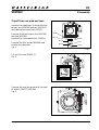
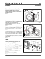
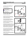
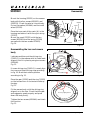
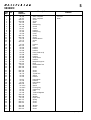
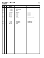
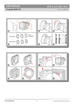
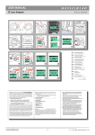
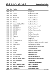
Service Manual
COPYRIGHT ' 2000 ANDERS ENGSTR M
903SWCOM.EPS
ANDERS ENGSTR M, ILLUSTRAT R
stra v gen 46
430 91 H N
tel/fax 031- 96 84 64
[email protected]
001027
January 2001
Victor Hasselblad AB
Göteborg Sweden
Copyright © 2001 by Victor Hasselblad AB. All rights reserved. No parts of this material may be reproduced, stored
in retrieval system or transmitted, in any form or by any means, electronic, mechanical, photocopy, recording, or
otherwise, without the prior written permission of the Company.
Contents list
903SWC
1.
General description
2.
Tools
3.
Disassembly
4.
Reassembly
5.
Exploded view: Shell
6.
Exploded view: Mechanism plate
7.
Exploded view: Viewfinder SWC
Revision 0
January 2001
Related Service Infos
903SWC
12/96
Tripod foot adapter/kits
05/97
New tripod foot
20/97
New camera shell
04/01
New CD-ROM - Version 2.0
Revision 0
January 2001
1
903SWC
General description
Camera type:
Mechanical wide-angle camera with a permanently attached 38
mm Biogon lens, and detachable optical viewfinder and
optional interchangeable film magazines.
Film format and film
choices:
6x6 cm and 6x4.5 cm with different magazines; 120 and 220
with roll films, 70 mm perforated long rolls and Polaroid film
with different magazines.
Lens:
Zeiss Biogon CF 4.5/38 mm T*. True wide-angle lens with
91º diagonal (72º horizontal) angle of view and Ø60 front
bayonet mount.
Viewfinder:
Detachable optical viewfinder with built-in spirit level and
built-in magnifier for reading lens scales through the viewfinder.
Focusing:
Focusing range of lens: 0.3 m to infinity. Depth-of-field range:
3 m to infinity at f/4.5 and 0.65 m to infinity at f/22.
Shutter:
Leaf shutter in lens, 1-1/500 s and flash synchronisation at all
shutter speeds.
Film advance:
Simultaneous manual shutter winding and film advance.
Foldable winding crank.
Camera body:
One-piece cast aluminium alloy shell with 1/4" and 3/8"
threads and plate for Tripod quick-coupling attachment.
System compatibility:
The 903SWC accepts all film magazines in the Hasselblad
system. The Biogon lens will accept Ø60 filters and Softars as
well as lens shades, fixed or professional.
Dimensions:
Camera body with lens and film magazine A12 (LxWxH):
147x112x153 mm (5.8"x4.4"x6.0").
Weight:
Camera body with lens and film magazine A12: 1340 g
(2 lb 15 oz.)
Revision 0
January 2001
2
Tools
903SWC
Tool No.
Description
Used for
902 894
Focusing gauge SWC
Focus the Biogon lens in the same way
as other Hasselblad lenses. Can be used
with all horizontal collimators.
109950 0747 000
Biogon adapter for V-2223 Adaption between the shutter function
gauge V-2223 and the Biogon lens.
The shutter can consequently be
repaired and the lens can be completed
before the assembly to the camera
body.
102165 0000 901
Wrench
Engraved ring
104867 8005 906
Wrench
Front lens group
104117 0064 903
Wrench
Rear lens group
Additional tools for the lens shutter, please see the Service Manual CF lenses.
Revision 0
January 2001
3:1
903SWC
Disassembly
Tripod Foot, rear plate and cone
Remove the viewfinder. Unscrew the four
screws, two (829790) and two (829760)
and remove the tripod foot (30735).
Unscrew the three screws, two (823783)
and one (823780).
Remove the intermediate foot (22821).
823640
22821
823780
823783
30735
Unscrew the four screws (823640) and
remove the rear plate.
Fig. 1
829790
829760
Fig. 1
90301.EPS
001026
Lift out the cone (13435-1).
Fig. 2
13435-1
Fig. 2
90302.EPS
001026
Unscrew the rear lens group with the help
of wrench 104117 0064 903.
Fig. 3
Fig. 3
90303.EPS
Revision 0
001026
January 2001
3:2
903SWC
Disassembly
Make sure the camera is released, then
remove the release lever (13332-1).
Unscrew the screw (822002) and remove
the catch (21165).
Fig. 4
21165
822002
820046
13332-1
The driving ring (21081-1) consists of two
rings, mark their relative position.
Unhook the spring (814707) from the
washer (810928).
Fig. 5
Fig. 4
90304.EPS
001026
"Mark"
Unscrew the three screws (820046) to free
the driving ring (21081-1) from the lens.
Fig. 4
The camera body can now be lifted from the
lens. Do not loose the gear (13320) and the
ring (13322) from the rear part of the lens!
810928
Lift out the driving ring (21081-1) from the
camera body.
Fig. 5
Crank
13320
13322
814707
21081-1
Fig. 5
820015
90305.EPS
22335
001026
Unscrew the two screws (821662) and
remove the spring (22328).
823640
810944
22331
A
22328
Unscrew the two screws (823640) and
remove the outer part of the crank (22331).
Remove the nylon string (22327) and lift
out the inner part of the crank (A).
Remove the tooth wheel (22335) and the
washer (810944).
Unscrew the four screws (820013 and
820015)
Remove the housing (22323).
Fig. 6
Revision 0
820013
22323
22327
821662
Fig. 6
90306.EPS
001211
January 2001
3:3
903SWC
Disassembly
Unscrew the screw (820047) and lift out
the complete mechanism plate (30367-1).
Fig. 7
30367-1
Take out the spacer (810721) and the
washer (810928) from the shell (circular
area fig. 8).
820047
Fig. 7
90307.EPS
001026
Mechanism plate (30367-1)
810721
13337
Unhook the spring (814705) from the
bracket (12873).
822001
816709
810928
816751
12873
Lift of the catch (13427-1) incl. the signal
(20737) and the spring (814705). Remove
the clip (817112) and disconnect the signal
incl. the spring (814705) from the catch.
Unscrew the screw (822031) and remove
the signal release mechanism (13429).
Unscrew the screw (825002), which is
secured with loctite, and separate the
driving gear (13343-1) and the driving
ratchet wheel (13340).
816702
810542
13343-1
814705
13340
817112
822031
30361-1
825002
13427-1
13429
20737
90308.EPS
001026
Unscrew the screw (822001), remove the
spring (816709) and the bracket (12873).
Fig. 8
Remove the release mechanism (13337).
Remove the spring (816751), the washer
(810542) and the spring (816702) from the
release mechanism.
Fig. 8
Revision 0
January 2001
4:1
903SWC
Reassembly
Lubricate the camera as detailed in the
appropriate lubrication chart. Use the
lubricants listed below:
= Isoflex Topas L32
= Isoflex PDP-48
= Loctite, e.g. Loctite 243
= Safety lacquer
Mechanism plate (30367-1)
Lubricate according to fig. 9.
Attach the spring (816702), the washer
(810542) and the spring (816751) to the
release mechanism (13337).
Fig. 9
90308.EPS
001026
Mount the release mechanism to the
mechanism plate (30361-1) and place the
two springs according to Fig. 10 A.
816751
Fit the bracket (12873) and the spring
(816709) into position and secure them
with the screw (822001).
816702
A
90311.EPS
Reassemble the driving gear (13343-1) and
the driving ratchet wheel (13340) according
to fig. 10 B and secure them with the screw
(825002). Make sure that the pawl and the
spring (816506) are in correct position (in
relation to the driving ratchet wheel).
Refit the signal release mechanism (13429)
and secure it with the screw (822031).
Fit the signal (20737) incl. the spring
(814705) to the catch (13427-1) and secure
it with the clip (817112).
Connect the spring (814705) to the bracket
(12873) and then fit the complete catch to
the mechanism plate.
Revision 0
13337
001030
822001
816709
816751
12873
816702
810542
13343-1
814705
13340
817112
816506
30361-1
822031
825002
13427-1
13429
20737
90308.EPS
B
Fig. 10
001026
January 2001
4:2
903SWC
Reassembly
Fitting the mechanism plate into the shell
Place the signal (20737) according to fig. 11.
20737
Fig. 11
90310.EPS
Fit the mechanism plate (30367-1) into the
shell. Fit the washer (810928) and the
spacer (810721) and secure them into
position using screw (820047).
Fig. 12
001023
30367-1
810928
810721
820047
Fig. 12
90307.EPS
Crank
001026
Lubricate according to fig. 13.
Fig. 13
Revision 0
90306.EPS
001211
January 2001
4:3
903SWC
Reassembly
Mount the housing (22323) on the camera
body with the four screws (820015) and
(820013). Check the axle so it turns freely.
Put on the washer (810944) and the tooth
wheel (22335).
820015
22335
823640
810944
Axle
22331
A
22328
Place the inner part of the crank (A) in the
housing and secure it with the nylon string
(22327).
Mount the crank (22321) with the two
screws (823640) and the spring (22328)
secured with the two screws 821662).
Fig. 14
Reassembling the lens and camera
body
820013
22323
821662
22327
Fig. 14
90306.EPS
001211
"Mark"
Lubricate and then put the driving ring
(21081-1) in the camera with its index mark
aligned. Hold it in place by using two screws
(820046).
Fig. 15
If a new driving ring (21081-1) is used, align
the inner and outer driving rings according
to fig. 16. Mark their relative position
according to fig. 15.
820046
810928
21081-1
814707
13320
13322
Fig. 15
Place the gear (13320) and the ring (13322)
on the lens and turn it clockwise to take up
the play.
Fig. 15
Fit the camera body, with the driving ring
aligned, on to the lens. Check that the gear
and coggsector mesh properly and press
down the body firmly.
Tighten the two screws (820046) and check
the function.
Fig. 15
Driving ring alignment
90309.EPS
001023
Revision 0
Fig. 16
January 2001
4:4
903SWC
Reassembly
Check the release sequence:
Cock the camera and move the outer driving
ring slowly towards the release mechanism
(13337). Free the release mechanism by
hand and the shutter should release at a
point just before the release mechanism
leaves the nylon stop (13295).
Fig. 17
13295
13337
90312.EPS
Fig. 17
010130
If the shutter releases too early, or not at all,
it is adjusted by changing the mesh between
the gear (13320) and the toothed segment
(13346). For a small adjustment, turn the
gear (13320) 180º.
Fig. 18
13346
Lens
90309.EPS
001023
13320
Fig. 18
Fit the catch (21165) and tighten the screw
(822002) and one screw (820046).
Install the release lever (13332-1) and
engage the spring (816709). Connect the
spring (814707) to the washer (810928)
according to the circular area and check the
release sequence again.
Fig. 19
21165
822002
816709
820046
13332-1
Fig. 19
90304.EPS
001026
Revision 0
January 2001
4:5
903SWC
Reassembly
Re-install the rear lens group with the help
of wrench 104117 0064 903.
Fig. 20
Fig. 20
Install the cone (13435-1).
Fig. 21
Fit the rear plate (22603). Secure with the
four screws (823640). Check that the rear
plate is aligned with the rear edge of the
camera shell. If necessary adjust with
washers.
90303.EPS
001026
13435-1
Fig. 21
90302.EPS
001026
Note! The rear plate must not protrude over
the shell at any point.
Fit the intermediate foot (22821).
Secure with the two screws (823783) and
one (823780).
823640
22821
823780
Fit the tripod foot (30735) with the four
screws, two (829790) and two (829760).
Fig. 22
Mount the viewfinder.
823783
30735
829790
90301.EPS
829760
Fig. 22
001026
Revision 0
January 2001
COPYRIGHT ' 2000 ANDERS ENGSTR M
903SWC01.EPS
ANDERS ENGSTR M, ILLUSTRAT R
stra v gen 46
430 91 H N
tel/fax 031- 96 84 64
[email protected]
5
903SWC
001023
1
3
2
4
5
6
7
8
40
39
9
10
11
12
13
38
37
35
14
15
36
16
17
18
19
34
20
21
41
24
55
22
42
54
53
25
52
23
26
56
51
27
43
50
44
47
28
45
49
30
46
57
58
29
48
63
33
31
32
64
29
30
59
62
60
65
61
66
65
Revision 0
January 2001
5
903SWC
Pos Pcs
No.
1
Spare
Part No.
Description
2
3
4
5
1
1
2
1
1
1
40 356
40 357
824 607
821 608
22 274
414 434
6
7
8
9
10
1
1
1
1
1
20 948
13 417
22 597
13 418
22 599
11
12
13
14
15
1
1
1
1
1
816 759
821 206
13 134
13 137
812 501
Spring
Screw
Release button
Screw
Pin
16
17
18
19
20
1
1
1
1
1
22 595
812 201
22 594
22 591
22 589
Leather
Pin
Leather
Leather
Leather
21
22
23
24
25
1
1
1
2
1
13 633
22 588
22 590
13 466
22 592
Foam plastic strip
Leather
Leather
Strap button
Leather
26
27
28
29
30
1
2
1
1
2
22 585
831 502
22 821
823 780
823 783
Magazine support
Rivet
Intermediate foot
Screw
Screw
31
32
33
34
35
2
2
1
1
1
829 790
829 760
30 735
22 583
22 593
Screw
Screw
Tripod foot
Spacer
Leather
36
37
38
39
40
2
1
1
4
1
22 612
22 596
22 562
823 640
22 321-1
Name plate
Leather
Name plate
Screw
Spacer
41
42
43
44
45
1
1
1
1
3
21 081-1
13 322
13 320
13 346
820 046
Driving ring
Guide ring
Gear
Toothed segment
Screw
46
47
48
49
50
1
1
1
2
1
810 928
13 295
814 707
823 017
820 013
Washer
Nylon stop
Spring
Screw
Screw
51
52
53
2
2
1
810 408
820 019
822 002
Washer
Screw
Screw
Revision 0
Shell, complete
Shell, complete
Screw
Screw
Shoe
Plate spring
Remark
Chrome
Black
Socket
T-arm
Leather
Plate spring
Cover
January 2001
5
903SWC
Pos Pcs
No.
Spare
Part No.
Description
Remark
54
55
56
57
58
1
2
1
1
1
22 997
830 435
13 435 -1
13 394 -1
20 769 -1
Magazine hook
Screw
Cone, complete
Cone
Frame
59
60
1
4
4
4
4
12 871 -1
810 549
810 542
810 543
810 545
Foam strip
Washer
Washer
Washer
Washer
0,10 mm
0,15 mm
0,20 mm
0,30 mm
61
62
4
1
823 640
22 603
Screw
Rear plate
Please state serial No.
63
64
1
1
1
8
1
22 566
22 584
22 667
823 735
103 349
Foot
Tripod socket
Tripod socket
Screw
Slide
65
66
Revision 0
Previous type tripod foot
Standard 1/4"
Optional 3/8"
January 2001
6
COPYRIGHT ' 2000 ANDERS ENGSTR M
903SWC02.EPS
ANDERS ENGSTR M, ILLUSTRAT R
stra v gen 46
430 91 H N
tel/fax 031- 96 84 64
[email protected]
1
2
3
001120
4
5
6
10
8
12
7
36
11
9
35
34
13
14
15
16
33
32
17
31
19
18
30
20
29
21
22
26
27
28
Revision 0
25
24
23
January 2001
6
903SWC
Pos Pcs
No.
Description
Spare
Part No.
1
2
3
4
5
1
2
1
1
1
22 323
820 015
810 944
22 335
22 331
Housing
Screw
Washer
Tooth wheel
Crank
6
7
8
9
10
2
1
2
1
2
821 662
22 328
823 640
22 327
820 013
Screw
Spring
Screw
Nylon string
Screw
11
12
13
14
15
1
1
1
1
1
810 721
30 367 -1
13 337
816 702
810 542
Spacer
Mechanism plate, complete
Release mechanism
Spring
Washer
16
17
18
19
20
1
1
1
1
1
816 751
13 343 -1
13 429
822 031
13 427 -1
Spring
Driving gear
Signal release mechanism
Screw
Catch
21
22
23
24
25
1
1
1
1
1
814 705
817 112
20 737
814 505
816 606
Spring
Clip
Signal
Spring
Spring
26
27
28
29
30
1
2
1
1
1
825 002
811 106
820 047
30 361 -1
816 506
Screw
Pin
Screw
Mechanism plate
Spring
31
32
33
34
35
36
1
1
1
1
1
1
12 873
816 709
822 001
13 340
13 332 -1
21 165
Bracket
Spring
Screw
Driving ratchet wheel
Release lever
Catch
Revision 0
Remark
January 2001
430 91 H N
tel/fax 031- 96 84 64
[email protected]
7
Viewfinder SWC
1
3
2
4
18
17
19
5
6
16
7
15
14
8
9
13
10
12
11
Revision 0
January 2001
7
Viewfinder SWC
Pos Pcs
No.
Spare
Part No.
Description
1
2
3
4
5
1
2
1
1
2
52 036/01
52 036/02
52 036/03
52 036/04
52 036/05
Libell
Cushion
Housing, upper
Glass plate
String
6
7
8
9
10
1
2
1
1
4
52 036/06
52 036/07
52 036/08
52 036/09
52 036/10
Housing, lower
Screw
Catch
Foot
Screw
11
12
13
14
15
1
1
2
1
1
52 036/11
52 036/12
52 036/13
52 036/14
52 036/15
Screw
Plate spring
Steel ball
Plate spring
Name plate
16
17
18
19
2
1
1
1
52 036/16
52 036/17
52 036/18
52 036/19
Screw
Lens element
Eye piece
Rubber eye cup
Revision 0
Remark
January 2001