1
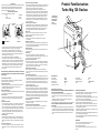
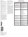
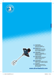
®
Thankyou for choosing this product
Silverline Tools 3 Year Guarantee
• This guarantee becomes effective at the date of retail purchase.
PLEASE KEEP YOUR RECEIPT.
• If this product develops a fault within 30 days of purchase, return it to the
stockist where it was purchased, with your receipt, stating details of the fault.
You will receive a replacement or refund.
• If this product develops a fault within 3 years of purchase return it to;
Silverline Tools Service Centre
PO Box 2988
Yeovil
BA21 1WU
Include your original receipt, details of the fault, your name and address, place and
date of purchase. We do not refund carriage. All product should be in a suitably
clean and safe state for repair, and should be packaged carefully to prevent damage
or injury during transportation. We may reject unsuitable or unsafe deliveries.
• You must provide proof of purchase before any work can be carried out.
• All work will be carried out by Silverline Tools or its authorised repair agents.
• Any parts which are replaced will become the property of Silverline Tools.
• The repair or replacement of the product will not extend the period of guarantee.
• The repair or replacement of your product under guarantee provides benefits which
are additional to and do not affect your statutory rights as a consumer.
What is covered:
• The repair of the product, if found to be defective due to faulty materials or workmanship
within 3 years of purchase. If any part is no longer available or out of manufacture,
Silverline Tools will replace it with a functional replacement part.
• Use of the product in the UK.
What is not covered:
Silverline Tools does not guarantee repairs required as a result of:
• Normal wear and tear Eg blades, brushes, belts, bulbs, batteries etc.
• Accidental damage, faults caused by negligent use or care,
misuse, neglect, careless operation or handling of the product.
• Use of the product for anything other than normal domestic purposes.
• Change or modification of the product in any way.
• Use of parts and accessories which are not Silverline Tools genuine components.
• Faulty installation (except installed by Silverline Tools).
• Repairs or alterations carried out by parties other than
Silverline Tools or its authorised repair agents.
User’s Manual
Turbo Mig 130 Gasless
Product Code 427677
© March 2008
Introduction
Carefully read and understand this manual and any label attached to
the tool before use. Keep these instructions with the product for
future reference. Ensure all persons who use and service this
product are acquainted with this manual.
Electrical Safety Information
• The wires in this product are coloured:
Blue
Neutral (N)
Brown
Live (L)
Green & Yellow Earth (E)
N
BLUE
(Neutral)
E
L
FUSE
L
FUSE
GREEN/YELLOW
OR GREEN
N
BROWN
(Live)
Double Insulated
BLUE
(Neutral)
FUSE
FUSE
E
BROWN
(Live)
Earthed
• As the colours may not correspond with the coloured markings
identifying the terminals in your plug, proceed as follows.
• The wire which is coloured blue must be connected to the
terminal which is marked with the letter N or coloured black, the
wire which is coloured brown must be connected to the terminal
which is marked L or coloured red.
• This appliance must be protected by a suitable fuse.
• To prevent fire or shock hazard, do not expose this product to
rain/water or moisture. There are no user serviceable parts inside
except those referred to in this manual. Always refer servicing to
qualified service personnel. Never remove any part of the casing
unless qualified to do so; this unit contains dangerous voltages.
• Use of a residual current device (RCD) will reduce the risk of
electric shock.
NEVER CONNECT THE BROWN OR BLUE WIRE TO THE EARTH
PIN OF THE 13 AMP PLUG. IF IN DOUBT CONSULT A QUALIFIED
ELECTRICIAN
General Safety Instructions
Even when used as prescribed it is not possible to eliminate all
residual risk factors. Use with caution.
Keep guards in position
• Always keep guards in position, in good working order, correctly
adjusted and aligned. Never attempt to use a power tool
without any guard supplied with it.
Remove adjusting keys
• Always check to see that keys and adjusting wrenches are removed
from power tool before turning on.
Clean work area
• Accidents occur where benches and work areas are cluttered or
dirty, floors must be kept clear, avoid working where the floor is
slippery.
Dangerous environment
• Do not use power tools in damp or wet conditions, or expose them
to rain. Provide adequate surrounding work space and keep are
well lit. Do not use power tools where there is a risk of explosion or
fire from combustible material, flammable liquids, flammable gases or dust of an explosive nature. When using power tools avoid contact with any earthed items such as pipes, radiators, cookers, refrigerators, metal baths and taps.
Children & pets
• Children and pets should always be kept at a safe distance from
your work. Make your workshop child-proof. Lock tool away where
children can’t get access to them. Remove batteries from cordless
tools.
Use the correct power tool
• Don’t force, or attempt to use a power tool for a purpose it was not
designed for. Do not use a small tool to do the job of a heavy duty
tool.
Wear correct clothing and footwear.
• Don’t wear loose clothing, neckties or jewellery or other items which
may get caught in moving parts. Wear non-slip footwear, cover or
tie back long hair. Use safety footwear if necessary.
• Wear safety goggles at all times, every day glasses are not
sufficient for eye protection, as lenses are not impact resistant and
could shatter. Use an approved face or dust mask when operation
creates dust. Ensure dust extraction equipment is functioning and correctly used. Hearing protection should be used if the sound
intensity level for the operator could exceed 85dB(A). Use a hard
hat where there is a risk of falling objects or striking your head on
low level obstructions.
Protect yourself from vibration.
• Hand held power tools may produce vibration. Vibration can cause disease. Gloves to keep the operator warm and dry and therefore
maintain good blood circulation in the fingers may help. This tool
has not been designed for extended or industrial operation.
Secure work
• Always secure work. Where practical use a clamp or vice, it will
allow you to use both hands to operate your power tool.
Keep your balance
• Don’t over reach, keep proper footing at all times to ensure
correct balance.
Maintain your power tool
• Keep your power tool in good working order, keep tools sharp and
clean for best and safest performance. Ensure ventilation holes are
kept clean and unrestricted at all times.
Always disconnect.
• Before changing tools, always ensure they are disconnected from
the power source.
Accessories
• The use of any attachment or accessory other than those
mentioned in this manual could result in damage or injury. The use
of improper accessories could be dangerous.
Never stand on your power tool
• Standing on your power tool or its stand could cause serious injury
if the tool is tipped or if the cutting tool is accidentally contacted. Do
not store materials above or near the tool so that it is necessary to
stand on the tool or its stand to reach them.
Switch off before connecting.
• Ensure the power tool is switched off before connecting to the
power source. If the power tool stops unexpectedly turn the power
switch to off.
Do not abuse the power cord.
• Be sure your cable/extension cable is properly wired and in good
condition. Always replace a damaged cable/extension cable or have
it repaired by a qualified person before using it. Never yank or pull
the cable to disconnect it from the power socket. Never carry your
power tool by it’s cable. Keep the cable away from damp, heat, oil,
solvents, and sharp edges.
Check for damaged or missing parts.
• Before each use check if any part of the power tool is damaged or missing, check carefully that it will operate properly and perform its
intended function. Check alignment of moving parts for binding. Any
guard or other part that is damaged should be correctly repaired or replaced. Do not use if the power switch does not turn the power on
and off. Check any other condition that may affect the safety of the
power tool. DO NOT USE IF DEFECTIVE.
Direction of feed
• Feed work into a blade or cutter against the direction of rotation of
the blade or cutter only.
Don’t leave the tool running unattended
• Always wait until your power tool has come to a complete stop
before leaving it and then disconnect from power source.
Product Familiarisation
Turbo Mig 130 Gasless
1. On/off switch
2. Output setting
3. Amp selector
4. Earth clamp
5. Torch
6. Carry strap
6
1
3
2
4
SPECIFICATION
Input voltage: No-load voltage: Current range:
Rated duty cycle: Adjustment positions: 230V
20-30V
55-120A
10%
4
Additional safety instructions
BEFORE OPERATING THE WELDER YOU MUST OBSERVE THE
SAFETY NOTICES GIVEN BELOW
• Electrical repairs must be carried out by a qualified approved
engineer and only with the welder disconnected from the power
source.
• Operating the welder with the covers removed is prohibited.
• Ensure that the unit is correctly set up.
• MIG welders are easy and safe to operate under normal conditions.
DO NOT OPERATE THE WELDER IN THE RAIN OR IN DAMP
CONDITIONS.
• Do not attempt to lift the welder with the gas bottle mounted on the
rear platform always remove the gas bottle before lifting the welder.
• The unit can be used on an inclined flat surface of up to 15 degrees
however if wheels are fitted to the welder ensure that you check
them.
5
Input capacity:
Class of insulation: Applied welding wire: Fuse:
3.5kW
H
0.8mm flux wire
13A
ADDITIONAL PRECAUTIONS
• All flammable materials must be removed from the welding area.
• DO NOT strike an Arc on or near the gas bottle.
• DO NOT attempt to weld fuel or gas containers.
• Toxic gases are given off during the MIG welding process, always
ensure that you weld in a well ventilated area.
• Always use a face shield or welding helmet fitted with the correct
glass filter. Never use damaged safety equipment.
• Wear welding gloves at all times when welding. They will protect
hands from ultra violet radiation and the heat of the Arc. We also
recommend wearing overalls.
• When welding at higher settings a leather apron should be worn to
protect the operator from spatter.
• When welding in the overhead position suitable headwear should
be worn to protect the head and neck.
• It is recommended that industrial footwear including steel toe caps
are worn when welding.
IMPORTANT
• These units must never be exposed to rain or snow.
• Do not use in a wet or damp environment.
• Do not attempt to thaw pipes.
The units should be connected to the mains supply via a circuit
breaker.
SETTING UP THE WELDER
To load a new wire reel follow the procedure below:
1. Remove the shroud from the torch and unscrew the contact tip.
2. Fit the wire reel onto the spindle ensuring the spring mounting is fitted correctly.
3. Locate the free end of the wire and cut off any distorted or
damaged wire ensuring that the wire does not become slack on
the reel.
4. Hinge back the pressure arm and feed the end of the wire into
the liner hole. Make sure that the wire is fitted so that it feeds into
the wire feed mechanism in a straight line.
5. Fasten the pressure arm down making sure that the MIG wire is in
the groove of the feed roller. Use the correct groove for the
thickness of wire being loaded.
6. To reverse the roller, undo the two securing screws and remove
the bracket, the roller can now be removed from the shaft and
reversed.
7. Hold the torch straight, switch the machine on and operate the
torch trigger, the wire feed roller should operate feeding wire
through the torch.
8. The wire will emerge from the end of the torch, feed the tip back
onto the wire, tighten it and replace the shroud.
THE FOLLOWING INSTRUCTIONS REFER ONLY TO MACHINES
WHICH USE GAS.
• Cylinder mounting brackets should be fitted to the rear of the
machine (where provided)
• Connect the gas tube by pushing the free end into the connector on
the regulator.
• To fit the gas cylinder to the regulator remove the cover from the
cylinder thread, and carefully screw on the regulator, gas will
escape until the regulator is fully fitted. Important always remove the
gas cylinder from the regulator when you have finished welding.
• To set the gas flow regulator turn the knob fully clockwise and then
anti-clockwise half to one turn depending on welding conditions.
• Voltage settings, the machine will have either two or four output
settings depending on the model. These are controlled by the
switches on the front panel (see fig. A). Switching from one setting
to another automatically increases or decreases the wire speed and
therefore weld output. On materials from 0.6mm to 1.3mm select
‘low’ settings and ‘high’ for thicker materials.
FIG A
1. Connect the earth clamp to the metal to be welded.
2. Set output and wire feed speed by selecting the appropriate
controls (see fig. A) depending on material type and thickness and
gauge of wire.
3. Connect the welder to the power source and switch on.
4. The wire should be trimmed to 3mm from the end of the tip.
5. Position the tip approximately 6mm from the point the weld is to
start.
6. Hold the mask in front of your eyes.
7. Press the trigger and when the Arc strikes, move the torch slowly
in the desired direction.
8. If there is not enough wire speed the Arc will hum and a mass will
form on the end of the wire, the wire speed should be increased.
Too high a wire speed will result in excessive spatter and sticking
against the work. When the wire speed is correct there will be a
steady smooth crackling sound. Porous welds means there is
insufficient gas flow and it should be increased.
9. Each welding machine has a rating plate on which can be found
a duty cycle, the welder can be set to deliver different output
currents at a duty cycle (expressed as a percentage). The
percentage represents the welding time in each ten minute cycle, for example 60 percent would mean that you weld for six minutes and then must let the welder cool for four minutes. If the welder is
used in excess of its duty cycles the temperature of some
components will become too hot and the thermal overload
protection will operate causing the welder not to operate, if this
happens the welder should be allowed to cool and after a short
time the thermal overload protection will reset itself and you can
continue welding.
TROUBLESHOOTING CHART
PROBLEM
Weld deposit too thick
• Welding voltage too low
• Torch moved over the work piece too slowly
Weld deposit incomplete and stringy
• Gas flow incorrect
• Torch moved over the work piece too quickly
Arc unstable, excessive spatter and weld porosity
• Rust, paint or grease on the work piece
• Torch held to far from the work piece
• No gas - check bottle content, connections regulator settings
• Incorrect gas for material
Wire repeatedly burns back
• Torch held to close to the work piece
• Break in the welding circuit
Possible causes:
Incorrect size of contact tip for wire
Contact tip damaged - replace
Contact tip loose - tighten
Feed rollers worn - replace
Welding wire corroded - replace
Pressure roller adjustment incorrect - adjust
Pressure roller sticking - lubricate or replace
Wire tangled on reel
Lack of weld penetration
• Welding output too low
• Wire feed speed too low
• Torch moved to fast
Burning holes in work piece
• Welding output too high
• Torch moved erratically or too slowly
No arc produced
• Earth lead or torch cable in open circuit
• Poor earth clamp connection
Welder does not operate (mains indicator not lit).
• Check mains connection
• Check supply fuse
Welder does not operate with trigger pressed.
• Check torch trigger and it’s connections
• Thermal overload cut out - allow to cool
HIGH
2 SETTINGS
LOW
HIGH
MIN
4 SETTINGS
LOW
MAX
Using the welder
Before welding ensure that
• You have read and understand the safety sections of this manual.
• All flammable material and containers have been removed from the
welding area.
• That there is good ventilation especially at the front and rear of the
welder. The welding process produces toxic gases and there must
be adequate ventilation to disperse them.
• That there is fire fighting equipment close to hand.
Possible Cause (s)