1
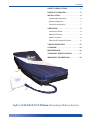
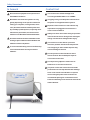
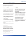
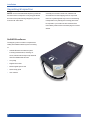
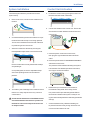
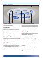
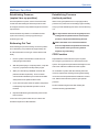
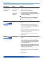
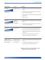
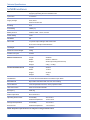
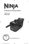
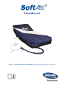
User Manual
SoftAir EXCELLENCE 250mm Alternating Mattress System
SoftAir EXCELLENCE User Manual
Important Notice
Before operating this medical equipment, it is
important to read this manual and understand
the operating instructions and safety
precautions. Failure to do so could result in
patient injury and/or damage to the product.
If you have any questions, please contact
your local Invacare sales office. Please refer
to the back page for contact details.
2
Contents
SAFETY PRECAUTIONS. . . . . . . . . . . . . . . 4
PRODUCT OVERVIEW. . . . . . . . . . . . . . . . 5
INSTALLATION . . . . . . . . . . . . . . . . . . . . . . 6
Unpacking & Inspection . . . . . . . . . . . . . . . 6
System Installation. . . . . . . . . . . . . . . . . . . 7
Control Unit Activation. . . . . . . . . . . . . . . . . 7
OPERATION. . . . . . . . . . . . . . . . . . . . . . . . . 8
Control Unit Panel. . . . . . . . . . . . . . . . . . . . 8
Mattress Function. . . . . . . . . . . . . . . . . . . . 9
Alarm Functions. . . . . . . . . . . . . . . . . . . . 10
Removal & Transport Function. . . . . . . . . 11
TROUBLESHOOTING. . . . . . . . . . . . . . . . 12
CLEANING. . . . . . . . . . . . . . . . . . . . . . . . . 14
MAINTENANCE. . . . . . . . . . . . . . . . . . . . . 16
TECHNICAL SPECIFICATIONS . . . . . . . . 17
WARRANTY INFORMATION. . . . . . . . . . . 18
SoftAir EXCELLENCE 250mm Alternating Mattress System
3
Safety Precautions
In General
Do not use this equipment in the presence of
flammable anesthetics.
Bed frames used with the systems can vary
greatly depending on the specific health care
setting (i.e. hospitals, nursing homes, home
care). A risk assessment must be performed
by a suitably qualified person, especially when
side rails are prescribed, to ensure the bed
meets the new IEC 60601-2-52 bed standard.
A risk assessment must be undertaken when
looking to place additional items between the
mattress surface and patient.
To ensure the alternating cells move effectively,
secure the bed sheets loosely around the
mattress.
Control Unit
The control unit is tested and approved
according to ISO-EN 60601-1 rev.2 & EMC
Only plug into a grounded power outlet and use
the power cord supplied with the system.
Exposure of the electronic Control Unit to any
liquid while it is plugged in could result in a
severe electrical hazard.
Always use fuses of the same rating as specified
in the Technical section. Using fuses with higher
ratings could result in damage and/or injury.
The electronic Control Unit is a precision
electronic product. Handle and transport with
care. Dropping or other sudden impacts may
result in damage to the unit.
Do not open the Control Unit due to risk of
electrical shock. Do not attempt to repair or
service the Control Unit.
Do not place any objects or items such as
blankets on or over the Control Unit.
The power cord to the Control Unit should be
positioned to avoid a trip hazard and/or damage
to the cord. Careful consideration is required
when routing the power cable. Invacare Ltd
recommends placing the cord under the bed
frame and attaching it to an electrical outlet at the
head of the bed.
4
Product Overview
SoftAIR Alternating Mattress System
The SoftAIR Excellence is a alternating mattress system
that provides pressure application and release to patients
who are vulnerable to or suffer from pressure ulcers. It is
designed to replace an existing mattress and can be used
on both standard and profiling bed frames.
Digital Control Unit
SoftAIR Excellence
The Control Unit provides the air supply to the mattress.
The SoftAIR Excellence Mattress comprises of 19 high
• It is controlled via a touch panel with integrated
density cells which all feature a permanently inflated
digital display. The alarm sounds when pressure
internal cell to prevent the patient “bottoming out” in
fails or power is interrupted. The Alarm Mute
the event of low pressure due to incorrect settings,
button silences the alarm for a maximum of 20
electrical or cell failure.
minutes. The alarm resumes if cause of failure is
This system includes three static head cells to provide
not resolved. The alarm will sound for up to two
hours following an interruption to power. As soon as
power is restored, the battery memory back up will
restore the latest pressure/ user settings.
• The Control Unit is fitted with an ‘on board’ battery.
The battery powers the alarm sounder in the event
of a total power failure or power interruption.
• The buttons on the control panel adjust the eight
comfort level settings.
• The system will automatically revert to Alternation
Mode after 20 minutes in Static Mode. See page 8
for further instructions.
• The Alarm LED indictor and Alarm Mute completes
the profile.
static “pillow” support for optimum user comfort, while
air pressure in the other 16 cells is alternated over a
10-12 minute cycle. This provides regular periods of
pressure reduction to aid blood and lymphatic flow to
vulnerable tissue.
The SoftAIR Excellence also includes an independent
heel zone of five low pressure micro cells for
individualised therapy to this sensitive area.
In addition, two permanently inflated side formers assist
in lateral support for the user and carer while increasing
the effectiveness of the one in three alternation cycle.
The hinged mattress base conforms to movements of
a profiling bed .
The visible and audible alarm function has a number of
indications depending on the cause of the failure.
On the side of the control unit are four male air connectors
for connecting the handle.
The rapid release handle includes a cap which can be
inserted into the handle during transportation. When in
transportation mode, tests have proven that the system
will stay inflated for up to 30 hours with no significant loss of
pressure. Whilst in transportation mode, the mattress will
remain in static mode (i.e. cells will not alternate). For this
reason, Invacare recommend that the alternating mode is
resumed once transportation is complete.
The mains supply to the Control Unit can be easily
disconnected and is designed to detach if tugged too
hard, protecting the internal wiring.
5
Installation
Unpacking & Inspection
NOTE: It is recommended that all packing materials
Carefully remove the Control Unit, mattress and
and instructions are kept in the carry bag provided in
accessories from the shipping cartons. Inspect all
the event of the product being shipped to your local
items for any damage that may have occurred during
Invacare Ltd sales office.
transportation. Any damaged or missing parts must
be reported to your local Invacare Ltd sales office
immediately. Please refer to the back page for contact
details.
SoftAIR Excellence
The shipping carton contains a complete and
readily assembled mattress system consisting
of:
• SoftAIR Excellence mattress system
including mattress base, CPR tag, air
hoses, handle with transport cap attached
and two inflatable side formers
• Carry Bag
• Digital Control Unit
• Medical grade power cord
• Quick setup guide
• User manual.
6
Installation
System Installation
The following describes the procedures for initial
system set up.
Control Unit Activation
a.Position the Control Unit by placing the hooks over
the foot board of the bed or side rails.
a.Remove all covers, sheets and the mattress from
the bed.
b.Connect the handle to the Control Unit. Ensure the
air hose does not kink between the bed frame and
Control Unit.
b. On a standard bed, position the mattress on top of
the bed frame with the top cover facing upwards.
The air hoses should be at the foot end of the bed
for positioning of the Control Unit.
c.Attach the mattress to the bed by securing the
two adjustable straps under each end of the bed.
c.Insert the power cord into the Control Unit,
then plug into a grounded 220V 50Hz electrical
outlet.
d.Press the power button for at least two seconds to
Ensure buckles are securely fastened and straps
are pulled tight.
On a profiling bed, secure the adjustable straps
around the profiling sections of the mattress
activate the Control Unit.
The pressure LEDs will flash indicating the system
has activated. For detailed operation instructions,
see Page 8: Control Unit Panel.
platform.
e.Please allow up to a maximum of 50 minutes for
d.To avoid any risk of damage to the mattress ensure
the mattress to fully inflate. Once ready, the first
there are no sharp objects which may come into
four pressure LED’s plus Alternating Mode LED will
contact with it.
illuminate to indicate that the system is ready for use
Check that the attachment of the Mattress does
not interfere with the movement or operation of
the bed. Do not secure straps to bed side rails
as straps will tear.
(system automatically defaults to Alternating Mode after
start-up)
f.Once the Mattress is fully inflated the bedding can
be placed. Fit sheets loosely enough to allow for free
movement of the mattress air cells.
7
Operation
Control Unit Panel
G
<
C
<
B
D
E
F
A
A Power Button
E Pressure Arrow Buttons
Turns system power on and off.
Press the arrows to increase or decrease the pressure
B Alarm LED
setting. Eight pressure settings are available from soft
The red light will flash and an audible alarm will sound
green LEDs illuminate to indicate which of the eight
to alert when the Control Unit or mattress pressure
settings is operational.
fails. The alarm has five different signals to indicate the
cause of the failure.
The audible alarm also sounds when power is switched
off. Press the Alarm Mute to silence.
C Alarm Mute Button
This button silences the audible alarm (on/ off). Audible
alarm will resume after 20 minutes if cause of failure is
not resolved.
D Mode Button
to hard (18mmHg to 60mmHg; 6mmHg per step). The
F Max Firm Button
Press to facilitate rapid inflation to maximum pressure
setting (60mmHg). After 30 minutes,
the system automatically reverts back to the previous
pressure setting for patient safety.
G Control Unit Lock / Unlock Button
Press for at least two seconds to lock the Control
Unit settings. A beep sounds and the amber LED
illuminates to indicate system is locked. When locked,
Press to select either Alternation Mode (alternative
only the Alarm Mute and Lock / Unlock buttons remain
cells cyclically inflating and deflating) or Static Mode
operational.
(all cells fully inflated with no dynamic alternation).
Press again for at least two seconds to unlock. Again a
Static Mode will automatically revert back to Alternation
beep sounds and the amber LED turns off.
Mode after 20 minutes.
The Control Unit will automatically unlock
in the event of a power failure.
8
Operation
Mattress Function
Establishing Pressure
(supine/ face up position)
Establishing Pressure
(inclined position)
Once the patient is in place, use the Pressure button
When moving the patient to a more upright position,
to select the best setting for effective pressure relief
pressure may need to be increased (by approximately
and support, based on the patients weight and comfort
20%) to provide added support and to avoid ‘bottoming
requirements.
out’.
Assess whether the patient is comfortable and the
It is important to return to the original pressure
system is functioning correctly by performing a
setting when the patient returns to the supine
‘bottoming out’ test.
position, and perform a Bottoming Out test.
Bottoming Out Test
When altering the pressure setting, ensure the patient
is not ‘bottoming out’ (insufficiently supported by the
air cells and therefore coming in contact with the bed
Wait a minimum of 10-12 minutes between
pressure adjustment and patient assessment,
as it may take a full cycle for the system to
adjust to any new setting.
base).
CPR Function
1.Ensure system is in alternation mode but is not
Rapid deflation of the mattress may be required
undergoing an alternation.
2.With the patient lying in a supine position, unzip the
top cover, just past the sacral (bottom) region.
3.Slide your hand along a deflated cell under the
patients sacral area (bottom). The inner static
cell will remain inflated but your hand should slide
easily between the patient and the base.
4.If your hand can pass under the patient, the patient
is adequately suspended and pressure can be
lowered.
for emergency procedures or to decommission the
system. Firmly pull the rapid release CPR tag from the
side of the mattress to deflate the whole system.
To re-inflate the system after the CPR tag has been
removed, replace the CPR tag ensuring both sealing
connectors are firmly attached and restart the Control
Unit. Wait for the mattress system to gain optimal
pressure.
Perform a Bottoming Out test after inflating the
mattress following rapid deflation.
5.Repeat the Bottoming Out test after pressure has
been lowered.
In the event of a system malfunction, the alarm will
activate and pressure LEDs will flash.
9
Operation
Alarm Function
The red Alarm LED will flash and an audible alert will
sound to indicate the control unit or mattress pressure
has failed. The LED will remain illuminated until
appropriate pressure is restored. The audible alarm
can be silenced by pressing the Alarm Mute button.
The system has five different alarm signals
which can be identified by five different Pressure
Setting illumination sequences. The signals and
corresponding Pressure Setting LED displays are
illustrated below
Display
Alarm Signal
Initial Failure Mattress has failed to reach minimum operational
pressure within 50 minutes
Low Pressure
Pressure has fallen 5mmHg or more below the setting
minimum
High Pressure
Pressure has exceeded the maximum setting by
10mmHg or more
Alternating Mattress has failed to commence alternation
Mode failure
AC power failure
If the alarm activates and the system fails to inflate or
loses pressure, please refer to the Troubleshooting
section on the following pages.
10
No pressure output due to mains power failure
Operation
Transport Function
System Removal
1.Prior to transport, switch the mode from
1.Switch off the Control Unit and disconnect from
alternating to static and wait five minutes for the
cells to inflate to maximum pressure.
2.Turn off the Control Unit and remove the rapid
release handle from the Control Unit.
3.Allow air to escape for a couple of seconds before
sealing with the attached transport cap. This will
soften the mattress surface for pressure relief
and comfort. If the patient is responsive, question
their comfort level based on current pressure and
adjust accordingly.
Invacare recommend that the alternating mode is
resumed once transportation is complete.
Regularly perform a ‘Bottoming Out’ test to
mains supply.
2.Remove the rapid release handle from the Control
Unit and disconnect the CPR tag.
3.Place the Control Unit and power cord on top of
the mattress and detach it from the bed frame.
4.Once the air has been released from all the cells,
roll up the mattress and return all items to the
Carry Bag for safe keeping.
Prior to restarting the system, ensure the
CPR tag is replaced and both sealing
connectors are firmly attached. Replace the
rapid release handle and firmly connect to the
Control Unit.
ensure the patient is appropriately supported
as air pressure is released from all internal
static cells as well as alternating sections.
11
Troubleshooting
This section provides basic troubleshooting support for the SoftAIR Excellence mattress system.
Alarm/ Fault
Cause
Solution
Control Unit does not
The Control Unit may
1.Check the Control Unit is connected to mains power outlet
operate; no display
not be attached to a
lights illuminate
power source
2.Check the Control Unit is switched on.
A fuse may need
3.Check the mains plug fuse (3 AMP) then check both
replacing in the
Control Unit
with the correct voltage.
Control Unit fuses (1 AMP) – fuses can be released using a
screwdriver to push and turn.
Do not try to open the Control Unit. Opening the unit
could cause personal injury or equipment damage.
Ensure the replacement of fuses is carried out in
accordance with local legislation.
Alarm LED
Initial failure
1. Reset the alarm – turn off Power and press the Alarm Mute
button.
2.Check the handle is intact, ensuring all four sealing
+ audible alarm
connectors are firmly fitted to the Control Unit and the air
hoses. Check the CPR tag is attached and both sealing
connectors are firmly secure.
3.Check all air hoses along the inside of the mattress – each
should be firmly connected. Check each air cell is securely
attached to its connecting air pipe.
4.Check all cells, pipes and hoses for any air leakage.
5.Switch on Power.
Alarm LED
Pressure too low
1. Reset the alarm – turn off Power and press the Alarm Mute
button.
+ audible alarm
2.Check the handle is intact, ensuring all four sealing
connectors are firmly fitted to the Control Unit and the air
hoses. Check the CPR tag is attached and both sealing
connectors are firmly secure.
3.Check all air hoses along the inside of the mattress – each
should be firmly connected. Check each air cell is securely
attached to its connecting air pipe.
4.Check all cells, pipes and hoses for any air leakage.
5.Check that the air filter cover is correctly secured and the
air filter is clean.
6.Switch on Power.
12
Troubleshooting
Alarm/Fault
Cause
Solution
Alarm LED
Pressure too high
1.Reset the alarm – turn off Power and press the Alarm Mute
button.
2.Disconnect the air hoses to reduce pressure – reconnect
+ audible alarm
when pressure has decreased.
3.Check for twists in the air hoses between the mattress and
Control Unit.
4.Switch on Power.
Alarm LED
Alternating
Mode Failure
+ audible alarm
Alarm LED
(no alternation)
1.Reset the alarm – turn off Power and press the Alarm Mute
button.
2.Disconnect the air hoses to reduce pressure – reconnect
when pressure has decreased.
AC power failure
1.Press the Alarm Mute button to silence the audible alarm.
2.Check the power cable is firmly plugged into the mains
outlet and the Control Unit; and check the mains power is
+ audible alarm
switched on.
3.Check the Control Unit fuse (1 AMP) – fuse can be
released using a screwdriver to push and turn.
Patient is sinking or
The pressure may
“bottoming out” whilst lying
be set too low for the
flat on the mattress
patient’s weight
1.Increase the pressure setting by pressing up the Pressure
arrow.
2.To check effective system performance, conduct a
“Bottoming Out” test as described on page 9.
If the problem is not resolved, please contact
your local Invacare Ltd sales office.
13
Maintenance & Cleaning
Infection Control and routine cleaning must be carried
1.Apply an intermediate level disinfectant (or a
out in accordance with your local Infection Control
solution of Sodium Hypochlorite or similar up to
Policy. It is suggested that all disinfection be done with
10,000 ppm available chlorine) to the top cover
a high grade disinfectant such as Sodium Hypochlorite
upper surface either by spraying or by hand
or similar (up to 10,000 ppm available chlorine).
application.
The top cover seams are sealed to prevent
2.Ensure the surface is completely covered with
moisture ingress and bacterial growth in the
the disinfectant and remains in contact with the
seam stitching.
surface according to manufacturer’s instructions.
Do not use high temperature autoclave or
Phenolic based products for cleaning.
It is recommended the system is cleaned
between patients and approximately every two
weeks if in constant use.
Mattress Top Cover
3. Remove disinfectant and rinse thoroughly.
4. Allow to air dry before use.
Mattress Base
Wipe down the outside shell with disinfectant (or a
solution of Sodium Hypochlorite or similar up to 10,000
ppm available chlorine), ensuring that all surfaces
If there are visible signs of body fluids and/ or
come in contact with the disinfectant. Rinse off well with
substances present, the top cover should be washed.
a clean damp cloth and air dry.
Top covers can be machine washed (up to 95ºC) using
disinfectant such as Sodium Hypochlorite or similar (up
to 10,000 ppm available chlorine).
Should the air cells require disinfecting, disconnect
the air cells from the base by unfastening the press
studs at each end and disconnect the air pipes from the
To establish the amount of disinfectant to use,
main air hoses before sliding each cell out from the cell
determine the amount of water in the washer and then
straps. Swab with a solution of Sodium Hypochlorite
follow the manufacturers’ instructions for dilution.
or similar (up to 10,000 ppm available chlorine). Dry
Soak the top cover in the disinfectant during the wash
cycle. Rinse well in clean water and dry thoroughly
before use.
Do not dry the top cover using the
Do not machine wash or dry the
air cells or mattress base.
Do not disassemble the mattress unless
heat cycle or a dryer. Please air dry or select a
cleaning is required. If cleaning or disinfecting
non-heat dry cycle.
is required, do not disconnect the pipes from
If there are no visible signs of body fluids and or
substances on the top cover, the top cover should be
sanitised.
14
thoroughly with a soft cloth before refastening.
individual Air Cells.
Maintenance & Cleaning
Handle
Air Filter Replacement
The exterior of the Handle can be
1.Switch off the power supply to the
periodically wiped using a cloth
dampened with disinfectant.
Control Unit
Ensure the Control Unit is disconnected from the
mains electricity supply before cleaning.
Do not spray disinfectant directly on to the
Control Unit.
2. Disconnect the power cord and air hoses.
3.Place the Control Unit on a flat surface with its back
panel uppermost (place soft cloth under unit to
prevent scratches).
4.Carefully remove the air filter cover. Remove and
Control Unit, or immerse the Control Unit in
discard the filter and fit with a new filter (there may
any type of liquid. This could result in a severe
be a small locking screw – use a small Phillips Head
electrical hazard as this equipment has no
screwdriver to remove this first).
protection against ingress of water.
This equipment is not suitable for use in the
presence of a flammable anesthetic mixture with
air or with oxygen or nitrous oxide.
5.Refit the air filter cover to the Control Unit. The Control
Unit is now ready for re-connection.
Good filter maintenance is critical to maintain
your SoftAIR system to optimal operating
Wipe down Control Unit with warm water containing
condition. Failure to keep the filters clean will
detergent (or with a solution of Sodium Hypochlorite or
result in system downtime and increase repair
similar) and dry thoroughly before use.
costs. It is recommended that the air filter be
replaced annually. Replacement air filters are
available from your local Invacare Ltd sales
office.
Fuse Replacement
1.Switch off the power supply to the Control Unit.
2.Remove the power cord from the electrical socket
on the side of the Control Unit.
3.Insert a small flat head screwdriver into the groove
and turn anti-clockwise (1/4 turn).
4.Remove the “blown” fuse from the fuse holder clip
and discard.
5.Insert a new fuse into the plug. Push against the
force of the spring and turn clockwise with the
screwdriver (1/4 turn).
Ensure the replacement of fuses is carried out
in accordance with local legislation.
15
Technical Specifications
SoftAIR Excellence
Cycle ControlPurpose designed distributor valve
supplying operating air to the inflatable cells
Cycle Time 12 minutes
Supply Voltage 220V, 50Hz
0.2A for Control Unit
IP Rating
IP41
Fuse Rating 1AMP (x1)
Battery Source VARTA, V80H, 1.2Vdc, 70mAh
Power Rating 12VA
Standards
CE
No of Cells 19 (cell in cell) including 3 static head cells
and 5 micro cells plus 2 side bolsters
Cell Height
230mm
Maximum Patient Weight
180kg
Product Life Cycle
2 Years
Mattress Dimensions
Length 2000mm
Width 830mm / 880mm
Height 250mm (including side formers)
Weight 9.5kg / 10.8kg
Control Unit Dimensions
Length 290mm
Width
170mm
Height 270mm
Weight 3.2kg
Cell Material 0.15mm TPU film laminated on 210 denier nylon fabric
Base Material Nylon fabric 420 denier with a 0.1mm TPU coating
Cover Material 100% Polyurethane surface, 100% polyester inside
Hose Connection Push on connection Handle
Emergency CPR Tag
Mode of Operation Non-continuous
Operating Environment Air humidity 30% to 70%
Ambient temperature 10ºC to 40ºC
Storage/Transportation
Air humidity
10% to 70%
Environment Ambient temperature -10°C to 60°C
NOTE: All product specifications are subject to change without notice.
16
Warranty Information
Invacare Ltd warrants each of its products to perform
Product life Cycle
in accordance with established specifications for
The product life cycle quoted can be exceeded if the
the following time periods, starting from the date the
product is maintained as per Invacare maintenance
product is shipped from Invacare Ltd.
and cleaning guildlines, The life cycle can also be
Control Units 2 years
Soft Goods
2 years
considerably reduced if the guildlines for maintenance
and cleaning are not followed or by unintended use
During the warranty period, Invacare Ltd either directly
or through its distributors, will repair or replace at
no charge, any products that are not performing in
accordance with established specifications, unless the
problem/ failure is due to:
• customer damage, negligence and/ or misuse
• unauthorised repairs
Items not covered under warranty include, but are
not limited to, stains, punctures, cuts, damages
to electrical cords, rips or tears, dents and/ or lost/
missing parts.
All products returned for warranty repairs must be
assigned a Return Autho risation Number prior to
return. Returns should include information describing
the problem and or requested repair and be sent
to your local Invacare Ltd sales office by prepaid
transportation. Invacare Ltd will return the repaired/
replaced product at no charge. Warranty repairs do not
extend the length of the warranty period.
Neither Invacare Ltd, its distributors, officers, directors,
employees or agents shall be liable for consequential
or other damages, including but no limited to personal
injury, loss, or any other expense, directly or indirectly
arising from the use of its products. The sole remedy
for breach of the limited warranty granted herein shall
be repair or replacement or the Invacare Ltd products.
17
Invacare UK Ltd.
Pencoed Technology Park, Pencoed, Bridgend, CF35 5AQ, UK
Tel: +44 1656 776200 Fax: +44 1656 776201
Technical Services Tel: +44 1656 776333 Fax: +44 1656 776330
Invacare Denmark
Invacare EC-Høng A/S
Østergade 3, DK-4270 Høng, Denmark
Tel: +45 58 85 27 22 Fax: +45 58 85 43 86
Invacare Norway
Invacare AS
Grensesvingen 9, Postboks 6230, Etterstad, N-0603 Oslo, Norway
Tel: +47 22 57 95 00 Fax: +47 22 57 95 01
Invacare Sweden
Invacare AB
Fagerstagatan 9, S-163 91 Spånga, Sweden
Tel: +46 8 761 70 90 Fax: +46 8 761 81 08
Invacare Ireland Ltd.
Unit 5, Seatown Business Campus, Seatown Road, SWORDS. County Dublin
Tel: +353 1 810 7084 Fax: +353 1 810 7085
www.invacare.com
Part number: 1550997
18