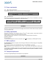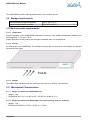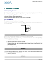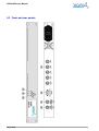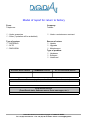
1
USER MANUAL Preliminary Version DIAPASON User Manual DIAPASON User Manual Preliminary Version History of modification of this document Revision Date Product version Modified sections Comments A 02/08/05 Preliminary - Creation B 17/08/05 WARNING This document contains preliminary information about DIAPASON DIGIDIA reserves the right to make changes at any time without prior notice in order to improve design and supply the best possible product. This document includes some confidential information. It can not be copied, otherwise reproduced, translated into another language or transmitted without prior written authorisation from DIGIDIA. Page 2/18 DIAPASON User Manual TABLE OF CONTENT 1INTRODUCTION.................................................................................................................... 4 2PRODUCT PRESENTATION................................................................................................ 5 3FEATURES AND PERFORMANCES.................................................................................... 6 3.1Generalities.................................................................................................................................... 6 3.1Generalities....................................................................................................................................6 3.2Input interfaces............................................................................................................................... interfaces...............................................................................................................................6 3.3Output interfaces............................................................................................................................ 6 interfaces............................................................................................................................6 3.4Control interfaces........................................................................................................................... 6 interfaces...........................................................................................................................6 3.5Power requirements....................................................................................................................... 7 requirements.......................................................................................................................7 3.6Safety requirements....................................................................................................................... .......................................................................................................................7 7 requirements 3.7EMC compliance............................................................................................................................ 7 compliance............................................................................................................................7 3.8Transport requirements.................................................................................................................. 7 requirements..................................................................................................................7 3.9Storage requirements..................................................................................................................... requirements.....................................................................................................................8 3.10Environmental requirements .......................................................................................................8 .......................................................................................................8 3.11 Mechanical Characteristics......................................................................................................... 8 Characteristics.........................................................................................................8 4GETTING STARTED............................................................................................................. 9 4.1Unpacking the rack........................................................................................................................ 9 rack........................................................................................................................9 4.2First start up................................................................................................................................... ...................................................................................................................................9 9 up 5MAINTENANCE................................................................................................................... 11 5.1First level maintenance................................................................................................................ 11 maintenance................................................................................................................11 5.2Precautionary maintenance......................................................................................................... 11 maintenance.........................................................................................................11 6APPENDIX........................................................................................................................... 13 6.1Glossary....................................................................................................................................... 13 6.1Glossary.......................................................................................................................................13 6.2References................................................................................................................................... 13 6.2References...................................................................................................................................13 6.3Front and rear panels................................................................................................................... 14 panels...................................................................................................................14 6.4Instructions in case of return to factory........................................................................................ 15 factory........................................................................................15 Page 3/18 DIAPASON User Manual 1 INTRODUCTION This document is the user manual for the DIAPASON product. It provides general information about the DIAPASON product, and detailed performance characteristics. This user manual is divided into 6 sections where the user can find all the necessary information for the installation, the usual operation and the first level maintenance of it. This part gives a general presentation of this manual. Section 1 – Introduction This part describes DIAPASON and its applications. Section 2 – Product presentation Section 3 – Features and performances This part provides detailed information about interfaces and operation of the DIAPASON This part provides information about installation, Section 4 – Getting started configuration and normal operation of the DIAPASON This part explains how to make first level maintenance. Section 5 – Maintenance The appendixes give additional detailed information Section 6 – Appendix about the DIAPASON and its operation. Page 4/18 DIAPASON User Manual 2 PRODUCT PRESENTATION DIAPASON belongs to the DRM product line developed by DIGIDIA. DIAPASON is to be used with ALTO DRM Content Server. The DIAPASON provided by DIGIDIA includes a high-density electronic board packaged in a 1U 19" rack and gives to the user, guarantees of reliability and robustness against severe environment including EMC constraints. Page 5/18 DIAPASON User Manual 3 FEATURES AND PERFORMANCES 3.1 Generalities DIAPASON modulator depicted in figure 1 provides: • Audio Synchronization for ALTO DRM Content Server; • Accurate Time Stamp insertion for ALTO DRM Content Server; 3.2 Input interfaces A three-digit label [xxx] enables to locate each connector (see Appendix). 3.2.1 • Audio synchronization signal GPS Antenna INPUT [101]: • GPS Signal Input • Output power supply of the active antenna 3.2.2 • GPS Antenna GPS Antenna INPUT [104]: • GPS Signal Input • Output power supply of the active antenna • Voltage: 5V • Current: 50 mA max. • GPS TNC connector (50 Ω) 3.3 Output interfaces • GPS Antenna OUTPUT [103]: • GPS Signal Output • GPS TNC connector (50 Ω) 3.4 Control interfaces 3.4.1 • Content Server Control RS232 connector [102]: • 3.4.2 DB9 connector LEDs on the Front panel DIAPASON equipment can detec two types of alarms: • Unlocked GPS [201]: GPS is still unlocked. This is probably due to antenna problem. • Comm [202]: Control of the content server is not present if this led is lighted • Power [202] is switched on when DIAPASON is switched on. Page 6/18 DIAPASON User Manual 3.5 Power requirements 3.5.1 Main voltage specifications The DIGIDIA equipment can be operated within the following ranges: Input voltage 85 to 264 volts 3.5.2 Frequency 47 to 63 Hz Fuse Protection Two fuses are located on the rear panel, inside the main socket [110], and identified by the label F1/F2. These fuses must be replaced by (or equivalent fuses): Main voltage 110/230 VAC Part N° F1T2A Rate 2A / 250V slow blow Manufacturer CEHESS Size 5 x 20 mm WARNING Equipment must be switch off and main line supply disconnected to network before all open operation or only by qualified staff. 3.6 Safety requirements Equipment connected to the mains by plug on TN or TT power systems, socket-outlet shall be installed near the equipment and shall be easily accessible. Class I equipment (only connected to a socket-outlet with a protective earth connection). Installation category II. Pollution degree 2. The DIAPASON equipment must be connected to earth in accordance to CEI364 (NFC15-100). 3.7 EMC compliance The DIAPASON equipment complies with the European Directives for Electromagnetic Compatibility (EMC 89/336/EEC). The equipment complies with the EN55022-B class and the EN50082-1 standards. EMC characteristics can be guaranteed only if input / output cables with appropriate shielding are used. It is necessary to establish a direct short connection between the earth connection point of the rack and any grounding point available on the bay or chassis in which the system is installed in order to meet EMC constraints. 3.8 Transport requirements Use only the original packing for the transport of any equipment. WARNING Page 7/18 DIAPASON User Manual The DIAPASON remains under guarantee only if this condition is met. 3.9 Storage requirements Recommended storage temperature Recommended relative humidity -20° C and +70° C. 10 to 80 % at 50°C 3.10 Environmental requirements 3.10.1 Temperature Correct operation of the DIAPASON equipment is insured in an ambient temperature between the following limits: + 0°C and + 50°C. Power dissipation of the product with all options installed does not exceed 20 W. 3.10.2 Cooling An internal fan cools DIAPASON. The airflow is entering the unit through the front panel and ejected through the rear panel. 3.10.3 Altitude The DIAPASON equipment can be used from sea level up to 4000 m over sea level. 3.11 Mechanical Characteristics 3.11.1 Weight and dimensions (DIAPASON only). Weight: 5 kg • Dimensions (W x D x H): 0.483 m (19’’) x 0.450 m x 0.044 m (1 U) • 3.11.2 Weight and dimensions (DIAPASON in its original packing, ready for shipment). Weight: 7 kg • Dimensions (WxDxH): 0.570 m * 0.570 m * 0.170 m • Page 8/18 DIAPASON User Manual 4 GETTING STARTED 4.1 Unpacking the rack Check the packing against transport damage. If it is the case, please contact the carrier immediately. Be careful while unpacking, the equipment may be heavy and must be handled with care. Keep the original packing for further transport. Check the equipment against transport damage. Check if the expected electric cable and the user manual are provided. 4.2 First start up 6,80 mm The equipment must be installed in a 19 inch bay. Several holes are available on the front panel to tighten the rack inside the cabinet, as presented in the following diagram. DRAWINGS 11 mm 8 mm WARNING: Service work described in this paragraph must be carried out by trained staff. Because of the weight of the rack, mounting it into a cabinet requires the rack to be supported by rails and not by the front panel only. 1. Install all necessary cables. 2. Make sure the equipment is correctly grounded. 3. Make sure the air flow around the equipment permits an optimal cooling. (Do not obstruct the blower output). No other equipment should be installed directly under and above the DIAPASON equipment. 4. Connect the power supply WARNING: To prevent damage to the equipment, check the main voltage, current and frequency available which must be in the range of DIGIDIA specifications. 1. Switch on your device WARNING: Page 9/18 DIAPASON User Manual DIAPASON can be controlled only through ALTO DRM Content Server. See ALTO User Manual for the control of the equipment. Page 10/ 10/18 DIAPASON User Manual 5 MAINTENANCE 5.1 First level maintenance Because of the digital technology used in the DIGIDIA equipment, the first level maintenance is restricted to an exchange of the whole equipment. WARNING: Make sure the operator has an easy and safe access to the equipment. 5.1.1 Fuses replacement Two fuses are located in the rear panel socket (see Appendix). To check or replace them: • Switch the equipment off, • Remove the main cable, • If the fuse(s) is (are) blown, replace it (them) by the original reference provided by DIGIDIA, • When the fuses are back in their housing, connect again the main cable and switch the equipment ON, • Check the equipment normal operation, • Power supply check. A staff trained by DIGIDIA can only do the internal power supply replacement. A specific replacement procedure provided by DIGIDIA must be used in this intervention. 5.1.2 Rack replacement See the following « Uninstalling the equipment » section. 5.1.3 Uninstalling the equipment WARNING: Make sure the operator has an easy and safe access to the equipment. Switch the equipment off, and remove its corresponding main cable. Remove all other cables. Remove all necessary screws, including its back plane screw. Extract the unit from its housing by pulling out the unit by its front panel handles. In case the equipment is replaced by a spare one, see « First start-up » section. Check that the place is still safe for the operation of the rest of the equipment in the bay. 5.2 Precautionary maintenance Page 11/ 11/18 DIAPASON User Manual 5.2.1 Fan The life span of the fan is typically 45 000 hours (about 5.1 years). DIGIDIA recommends changing them every five years. Fan can be changed during operation (Ref. 412H from PAPST) but contact the DIGIDIA customer service. Page 12/ 12/18 DIAPASON User Manual 6 APPENDIX 6.1 Glossary GPS : Global Positioning System 6.2 References [1] EN 550022-B: "Limits and methods of measurement of radio interferences characteristics of information technology equipment". [2] EN 50082-1: "Generic immunity standard –Part 1: Domestic commercial and light industry". Page 13/ 13/18 DIAPASON User Manual 6.3 Front and rear panels Page 14/ 14/18 DIAPASON User Manual 6.4 Instructions in case of return to factory In case you need to return your equipment to DIGIDIA for updating or maintenance, please use the following procedure: Call the hot line at DIGIDIA before shipping your equipment, in order to check whether it is really necessary to return it. The shipment back to DIGIDIA is organised by the customer and at his expense and DIGIDIA will organise and pay the return after repair to the customer’s company. If you are part of an EEC country, the shipment is at your expense until DIGIDIA’s premises. If you are outside EEC, the shipment is at your expense until RENNES SAINT-JACQUES airport (France). During the guarantee period, the repair is free of charge. If your equipment is out of guarantee and if you have no maintenance contract (*), DIGIDIA will send you by fax a quotation for this repair that you have to acknowledge by sending the form back. Always use the original packing in which the equipment had been delivered to you. Do not return any documentation or cables (power cord or other). Use the attached form to explain the reason of the return and, when necessary, the problems encountered. Send the equipment to: DIGIDIA Support Department Immeuble Orchis Les landes d'Apigné 35650 LE RHEU - France Tel: +33 (0)2 99 14 63 32 Fax: +33 (0)2 99 14 58 83 Email:[email protected] (*) If you want to set up a maintenance contract, please contact our sales department. Page 15/ 15/18 Model of report for return to factory From: Telephone: Company: Telefax: Under guarantee Other ( quotation will be submitted) Under a maintenance contract Type of system: SOPRANO ALTO DIAPASON Reason of return: Update Upgrade Maintenance Type of problem: Hardware Software Undefined EQUIPMENT SERIAL NUMBER FIRMWARE VERSION PC SOFTWARE NAME/VERSION EQUIPMENT SPECIFICITY (option, embedded boards, modem, etc.) PROBLEM SPECIFICATION (Front Panel state, Software menu, Error messages, etc.) Immeuble Orchis Les landes d'apigné -F-35560 LE RHEU Tel:+33 (0)2 99 14 63 32 - Fax:+33 (0)2 99 14 58 83 – Email: [email protected] ELECTROMAGNETIC COMPLIANCE STATEMENT (EEC directive 89/336 article 10) Manufacturer name: Address: DIGIDIA Immeuble Orchis Les landes d'apigné 35650 LE RHEU - FRANCE Equipment designation: XXXXXXX DIAPASON M. OLIVIER Pascal, Manager Declare having the strong presumption that the above designated equipment complies with the essential EEC89/336 directive requirements, by application of the standards listed below: NF EN 55022-B class NF EN 50082-1 Le Rheu, August 2005 Immeuble Orchis Les landes d'apigné -F-35560 LE RHEU Tel:+33 (0)2 99 14 63 32 - Fax:+33 (0)2 99 14 58 83 – Email: [email protected] SAFETY COMPLIANCE STATEMENT (EEC directive 73/23) Manufacturer name: Address: DIGIDIA Immeuble Orchis Les landes d'apigné 35650 LE RHEU - FRANCE Equipment designation: XXXXXXX DIAPASON M. OLIVIER Pascal, Manager Declare having the strong presumption that the above designated equipment complies with the essential EEC73/23 directive requirements, by application of the standards listed below: NF EN 60950 Le Rheu, August 2005 Immeuble Orchis Les landes d'apigné -F-35560 LE RHEU Tel:+33 (0)2 99 14 63 32 - Fax:+33 (0)2 99 14 58 83 – Email: [email protected]