1
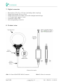
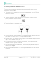
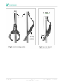
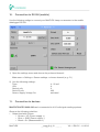
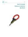
EN
User’s manual
Clamp-on-ammeter
MiniFLEX
1. Index
1. Index .................................................................................................................................... 2 2. Foreword .............................................................................................................................. 3 3. Safety instructions ................................................................................................................ 4 4. Description ........................................................................................................................... 5 5. Technical characteristics ....................................................................................................... 5 6. MiniFLEX MA101 sensor characteristics ................................................................................ 5 7. Digital converter ................................................................................................................... 6 8. Product view ........................................................................................................................ 6 9. Installing the MiniFLEX MA101 sensor .................................................................................. 7 10. Connection to DS 500 (mobile) ........................................................................................... 9 11. Connection to devices ........................................................................................................ 9 12. Disposal instructions ........................................................................................................ 10 MiniFLEX
page 2 of 10
V0.1 / EN-CV - 11/2012
V0.1 / EN-CV - 11/2012
2. Foreword
Dear customer,
thank you for purchasing our product. Please read the installation and operating
instructions carefully, before performing the installation and commissioning. Only if the
described regulations and notices are precisely observed, can the flawless function and
safe operation of the product be guaranteed.
Sales Office North
Am Oxer 28c
D-24955 Harrislee
Tel.: +49 (0) 461 700 20 25
Fax: +49 (0) 461 700 20 26
Mail: [email protected]
Web: http://www.cs-instruments.com
Sales Office South
Zindelsteiner Str. 15
D-78052 VS-Tannheim
Tel.: +49 (0) 7705 978 99 0
Fax: +49 (0) 7705 978 99 20
Mail: [email protected]
Web: http://www.cs-instruments.com
MiniFLEX
page 3 of 10
V0.1 / EN-CV - 11/2012
V0.1 / EN-CV - 11/2012
3. Safety instructions
Please check to see if these instructions correspond to the device type.
Observe all the instructions stated in this manual. It contains fundamental
information, which must be observed during installation, operation and
maintenance. Therefore, this manual must absolutely be read carefully by the
installer and the responsible operator/personnel before the installation,
commissioning and maintenance.
The operating instructions must always be accessible at the operation location
of the product.
In addition to these instructions, local and national regulations must be
observed if necessary.
In case of doubt or questions about this manual or the device, you should
contact CS Instruments GmbH.
Further safety instructions:
1. Trouble-free operation and reliability of the device can only be guaranteed if the device
is not subjected to any other climatic conditions than those stated under 'Specification‘.
2. General instructions and safety regulations for electric, light and heavy current plants,
including domestic safety regulations (e.g. VDE), have to be observed.
3. If device is to be connected to other devices (e.g. via PC) the circuitry has to be
designed most carefully. Internal connection in third party devices (e.g. connection
GND and earth) may result in not-permissible voltages impair- ing or destroying the
device or another device connected.
4. If there is a risk whatsoever involved in running it, the device has to be switched off
immediately and to be marked accordingly to avoid re-starting.
Operator safety may be a risk if:
• there is visible damage to the device.
• the device is not working as specified.
• the device has been stored under unsuitable conditions for a longer time.
In case of doubt, please return device to manufacturer for repair or maintenance.
5. Do not use this product as safety or emergency stop devices, or in any other
application where failure of the product could result in personal injury or material
damage.
MiniFLEX
page 4 of 10
V0.1 / EN-CV - 11/2012
V0.1 / EN-CV - 11/2012
4. Description
MiniFLEX.ACDC-400-040 is an AC RMS current sensor composed of a flexible active part
(Rogowski coil model MiniFLEX MA101) connected to a compact digital converter, capable
of measuring the current carried on a power conductor up to a value of 400 Aac. The
digital converter supplies an output of 4-20 mAdc in linear proportion to the measured
current.
5. Technical characteristics
•
•
•
•
•
•
•
•
•
(1)
Measurement range: from 5 Aac to 400 Aac
Fundamental frequency: from 45 Hz to 65 Hz
Output signal: from 4 mAdc to 20 mAdc
o 4 mAdc = 0 Aac
o 20 mAdc = 400 Aac
Maximum output: 21.6 mA
Load impedance: ≤ 300 Ω
Precision: ≤ 1 % Full scale in the measurement range 5…400 Aac (1)
Power supply: from 10 Vdc to 30 Vdc
Power consumption: ≤ 50 mA
Output lead with 3 wires (brown – blue – black)
Reference conditions 23°C ± 5°C, R.H. 20…75%, continuous external magnetic field < 40A/m, absence of magnetic and electrical fields, measured
signal frequency 50 Hz ± 1 Hz sine wave, sensor mounting as per Fig. 3, cable diameter clamped 14…24mm
6. MiniFLEX MA101 sensor characteristics
•
•
•
•
•
•
•
•
•
•
Sensor length: 140 mm ± 5mm
Maximum clamp capacity: 40 mm ± 2mm
Length of cable for connection to digital converter: 290 cm ± 5 cm
∅ of sensor: approx. 5.5 mm
∅ of output lead: approx. 3 mm
Maximum temperature of clamped cable: ≤ 80°C
Protection rating: IP50
Self-extinguishing: UL94-V0
Service voltage ≤ 600 Vrms (CAT IV) / 1000 Vrms (CAT III)
Material class II, dual insulation, in compliance with EN61010-1 EN61010-2-032
MiniFLEX
page 5 of 10
V0.1 / EN-CV - 11/2012
V0.1 / EN-CV - 11/2012
7. Digital converter
•
•
•
•
•
•
Dimensions: 55 x 30 x 12.5 mm (excluding cable coupling)
Output lead length: 30 cm ± 2 cm
Output lead: three core cable, wires with straight terminal lugs
∅ of output lead: approx. 4 mm
Protection rating: IP54
Self-extinguishing: UL94-V0
8. Product view
View not in scale
Abb. 1: View of MiniFLEX MA101 sensor
MiniFLEX
Abb. 2: View of converter
page 6 of 10
V0.1 / EN-CV - 11/2012
V0.1 / EN-CV - 11/2012
9. Installing the MiniFLEX MA101 sensor
To ensure compliance with the stated measurement tolerance, the sensor must be
positioned as shown in fig. 3.
1) The sensor must be installed in an inclined position and inverted, with the "OK" label
visible to the operator.
2) There is a black arrow on the right-hand side of the sensor. The arrow must be
pointing towards the clamped conductor.
3) Press the yellow clip to release the sensor
4) Circle the cable with the sensor and lock the clamp, ensuring the yellow clip clicks into
place. Make sure the red sensor is correctly locked in its location.
5) Incline the sensor until the black fastening clip is in contact with the clamped conductor
(Fig. 3). Do not bend the sensor (Fig. 4).
6) To prevent the sensor from sliding along the conductor, fix the output lead to the
clamped conductor, e.g. using a cable tie.
7) Allow the sensor to lie in a natural position, without causing any distortion during the
fastening stage (Fig. 4).
8) The sensor should be positioned at a distance greater than 5 cm from other external
conductors
MiniFLEX
page 7 of 10
V0.1 / EN-CV - 11/2012
V0.1 / EN-CV - 11/2012
MiniFLEX
page 8 of 10
V0.1 / EN-CV - 11/2012
V0.1 / EN-CV - 11/2012
10.
Connection to DS 500 (mobile)
Use the following settigs to connect your MiniFLEX clamp-on-ammeter to the mobile
datalogger DS 500:
1) Open the settings menu and choose the preferred channel:
Main menu > Settings > Sensor settings > choose channel (e.g. C1)
2) Use the following settings:
Type:
Unit:
Scale 4 mA:
Scale 20 mA:
Sensor Supply Voltage On:
11.
4 - 20 mA
A
0
400
activated
Connection to devices
MiniFLEX.ACDC-0400-040 can be connected to 4-20 mA signal reading systems.
Observe the following polarities:
• Output lead with 3 wires:
o Brown = VP (Power supply +)
o Blue = GND (Power supply –)
o Black = S+ (Measurement +)
MiniFLEX
page 9 of 10
V0.1 / EN-CV - 11/2012
V0.1 / EN-CV - 11/2012
12.
Disposal instructions
The device must not be disposed in the regular domestic waste. Send the device directly
to us (sufficiently stamped), if it should be disposed. We will dispose the device
appropriate and environmentally sound.
MiniFLEX
page 10 of 10
V0.1 / EN-CV - 11/2012