1
Copier
d-Copia 12
SERVICE MANUAL
Code Y101700-5
PUBBLICATION ISSUED BY:
Olivetti TECNOST S.p.A.
Documentazione
77, Via Jervis - 10015 Ivrea (Italy)
Copyright © 2002, Olivetti
All rigths reserved
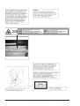
CAUTION
This product is a class 1 laser product that complies with 21CFR 1040.10 and 1040.11 of the CDRH standard and IEC825. This
means that this machine does not produce hazardous laser radiation. The use of controls, adjustments or performance of
procedures other than those specified herein may result in hazardous radiation exposure.
This laser radiation is not a danger to the skin, but when an exact focusing of the laser beam is achieved on the eye’s retina, there
is the danger of spot damage to the retina.
The following cautions must be observed to avoid exposure of the laser beam to your eyes at the time of servicing.
1) When a problem in the laser optical unit has occurred, the whole optical unit must be exchanged as a unit, not as individual
parts.
2) Do not look into the machine with the main switch turned on after removing the developer unit, toner cartridge, and drum
cartridge.
3) Do not look into the laser beam exposure slit of the laser optical unit with the connector connected when removing and
installing the optical system.
4) The middle frame contains the safety interlock switch.
Do not defeat the safety interlock by inserting wedges or other items into the switch slot.
Y101700-5
Service Manual
v
vi
Service Manual
Y101700-5
1. GENERAL
1.1 Main features
The d-Copia 12 copier has the following major
characteristics:
-
High-speed laser copying
· Since warm-up time is zero, copying can be started
immediately after the power switch is turned on.
· First-copy time is only 9.6 seconds (normal mode).
· Copying speed is 12 copies/min. which adapts to business use, allowing improvement of working efficiency.
- Digital high-quality image
· High-quality image copying with 600 dpi can be performed.
· In addition to the automatic exposure mode, the manual
exposure can be adjusted in five steps.
· The photo mode copying function which allows clear
copying of delicate halftone original images such as
monochrome photos and color photos can be used.
Y101700-5
- Substancial copying functions
· Zoom copying from 50% to 200% in 1% increments can
be performed.
· A maximum of 99 copies can be selected.
· Toner save mode for reducing toner consumption by
approximately 10% can be set.
- Environmentally friendly design
· Paper output tray is housed in the copier for space
saving.
· Preheat mode and auto power shut-off mode are provided to reduce power consumption in standby mode.
- Printer feature
· This copier is also a laser printer.
Service Manual
1-1
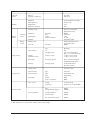
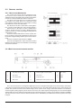
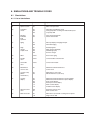
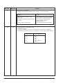
1.2 Specifications
1.2.1 Basic specifications of the copier
A. Basic specifications
Item
Spec.
Type
Copy system
Segment (class)
External dimensions (W × D × H) (mm)
Weight
Desktop
Dry, electrostatic
Digital personal copier
518 mm × 482.6 mm × 292.6 mm
Approx. 19Kg, (drum cartridges included)
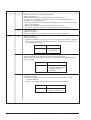
B. Operation specifications
Section
Item
Details
Paper feed
system
1 tray (250 sheets) + 1 single-sheet manual bypass
Paper size
Paper weight
Paper feed capacity
Kinds
Remark
A4, B5, A5 (Landscape)
56 – 80g/m2 Tray paper
250 sheets
Standard paper, specified paper, recycled paper
User adjustment of paper guide available
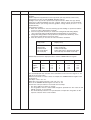
Paper size
Paper weight
Kinds *1
Remark
A4, B5, A5, B6, A6 (Landscape)
52 – 128g/m2
Standard paper, specified paper, recycled paper, OHP, Label,
Postal card
User adjustment of paper guide available
Tray paper
feed section
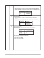
Paper size
Paper weight
Paper feed capacity
Kinds
Remark
8-1/2″ × 14″, 8-1/2 × 11″, 8-1/2″ × 5-1/2″ (Landscape)
15 – 21 lbs.
250 sheets
Standard paper, specified paper, recycled paper
User adjustment of paper guide available
Single-sheet
manual bypass
feed section
Paper size
8-1/2″ × 14″, 8-1/2 × 11″, 8-1/2″ × 5-1/2″, 3-1/2″ × 5-1/2″
(Landscape)
14 – 34.5 lbs.
Standard paper, specified paper, recycled paper, OHP, Label,
Postal card
User adjustment of paper guide available
Tray paper
feed section
AB system
Single-sheet
manual bypass
feed section
Paper
feed
setion
Spec.
Inch system
Paper weight
Kinds *1
Remark
∗1: OHP, Label, Postal card: each 1 pc.
1-2
Service Manual
Y101700-5
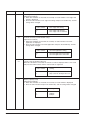
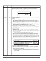
Section
Item
Details
Spec.
Paper exit
Exit way
Face down
section
Capacity of output tray
100 sheets
Original set
Center Registration (left edge)
Max. original size
B4 (10″ × 14″)
Original kinds
sheet
Original size detection
None
Scanning system
CCD sensor scanning by
lighting lamp scanner
Originals
CCD sensor
Optical
section
Scanning
section
Lighting lamp
Resolution
Type
Voltage
Power consumption
Gradation
Writing
section
Image forming
Writing system
Writing to OPC drum by the
semiconductor laser
Laser unit
Resolution
Type
OPC (30φ)
Photoconductor
Life
18k
Charging system
Saw -tooth charging with a
grid, / (–) scorotron discharge
Charger
Separation system
Transfer system
(+) DC corotron system
(–) DC corotron system
Developing
Developing system
Dry, 2-component magnetic
brush development system
Cleaning
Cleaning system
Counter blade system
(Counter to rotation)
Fusing system
Fusing section
400 dpi
Xenon lamp
1.5kV
11 ± 3W
256 gradations/8bit
600 dpi
Heat roller system
Upper heat roller
Type
Teflon roller
Lower heat roller
Type
Silicon rubber roller
Type
Halogen lamp
Heater lamp
Voltage
100V
Power consumption
800W
Voltage
Local AC voltage
Frequency
Common use for 50 and 60Hz
Power source
Electrical section
Power consumption
Max.
1000W
Average (during copying) *1)
310Wh/H
Average (stand-by) *1)
70Wh/H
Pre-heat mode *1)
40Wh/H
Auto power shut-off mode *1)
18Wh/H
*1) May fluctuate due to environmental conditions and the input voltage.
Y101700-5
Service Manual
1-3
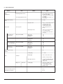
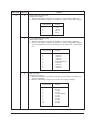
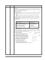
C. Copy performance
Section
Copy
magnification
Item
Details
Fixed magnification ratios
3R + 2E (AB system: 50, 70,
81, 100, 141, 200%)
(Inch system: 50, 64, 78, 100,
129, 200%)
50 ∼ 200% (151 steps in 1%
increments)
Zooming magnification ratios
Manual steps (manual,
photo)
Copy speed
Spec.
5 steps
Tray paper feed
9.6 sec. or below (A4), 9.4 sec.
or below (8-1/2" × 14")
Pre-heat mode: 16 sec.
or below / Auto powershut-off mode: 23 sec. or
below)
Manual paper feed
10.0 sec (Pre-heat mode: 16
sec. or below / Auto
power-shut-off mode: 23 sec.
or below)
First copy time
AB system: A4
(Landscape)
Copy speed (CPM)
Same size
Enlargement
Reduction
12
12
12
B5 (Landscape)
Copy speed (CPM)
Same size
Enlargement
Reduction
12
12
12
Inch system 8-1/2″
Copy speed (CPM)
Same size
10
Enlargement
Reduction
10
10
Same size
Enlargement
Reduction
12
12
12
× 14″ (Landscape)
8-1/2″ × 11″
(Landscape)
Copy speed (CPM)
Max. continuous copy
quantity
Void
99
Leading edge
1 ∼ 4mm
Trailing edge
4mm or less, 6mm or less
Void area
4.0mm or less (per side),
Image loss
OC mode
Side edge void area
machine with side edge void
0.5mm ∼ 4mm (Total of both
edge voids)
Leading edge
Same size: 3.0mm or less /
Enlarge (200%): 2.0mm
or less / Reduction (50%):
6.0mm or less
Warm-up time
0 sec.
Power save mode reset time
0 sec.
Paper jam recovery time
0 sec.
1-4
Service Manual
Y101700-5
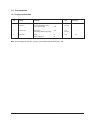
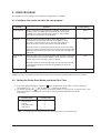
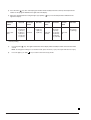
1.3 Consumables
1.3.1 Supply system table
No.
Name
Content
Life
1
Toner CA (Black)
with CA
Toner
(Toner Net Weight 210g)
Polyethylene bag
x10
Package
6.5K
per unit
1
x10
2
Developer
Developer
(Developer Net Weight 170g)
x10
25K
per unit
1
3
Drum kit
Drum
Drum fixing plate
x1
x1
25K
10
Note: Packed together with the machine: DR 25K/Developer UN/Process UN.
Y101700-5
Service Manual
1-5
1.4 Environmental conditions
1.5 Production control number
(lot No.) identification
The environmental conditions for assuring the copy
quality and the machine operations are as follows:
(Developing cartridge)
- Normal operating condition
• Temperature:20°C~25
• Humidity:65 ± 5%RH
- Acceptable operating condition
*: Destination
Division
- Optical condition
No.
EX Destination
A same pack
B same pack
G
H
Option Destination
A
B
P
Q
(Drum cartridge)
The label on the drum cartridge shows the date of
production (SOCC production).
(JAPAN production)
- Supply storage condition
1-6
Service Manual
Y101700-5
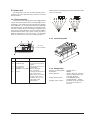
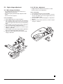
1.6 TD cartridge replacement
Division
No.
Ex production
Option
Same pack
1
2
3
1) Open the front and side cabinets of the copier.
2) Keep holding Toner lover, and
3) Carefully pull out Toner unit from the copier.
4) Put Toner unit in a collection bag immediately after removing
it from the copier.
*1 The production control label is not attached to the cartridge
of a China product.
Note: Never carry exposed Toner unit. Be sure to put it in the
collection bag.
Y101700-5
Service Manual
1-7
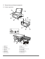
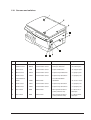
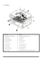
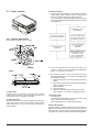
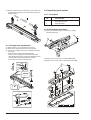
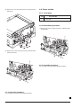
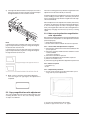
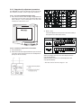
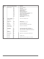
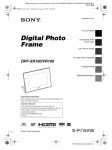
1.7 External views and internal components
1.7.1 General appearance
9
1
8
2
3
7
11
4
13
10
5
6
12
15
16
14
13
17
18
22
20
21
19
1
2
3
4
5
6
7
8
9
10
11
Original cover
Side cover
Manual bypass
Paper guides
Side cover open button
Front cover
Paper tray
Operation panel
Original table
Parallel interface
Paper output tray
1-8
12
13
14
15
16
17
18
19
20
21
22
Paper output tray extension
Handle
Power switch
Power cord socket
Toner cartridge lock release lever
Toner cartridge
Transfer charger
Photoconductive drum
Charger cleaner
Fusing unit release tab
Paper feed roller
Service Manual
Y101700-5
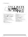
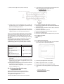
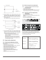
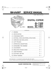
1.8 Operation panel
1 Exposure mode selector key and indicators
Use to sequentially select the exposure modes: AUTO, MANUAL (= ) or PHOTO ( ). Selected mode is shown by a
lit indicator.
2 Light ({) and dark ( ) keys and exposure indicators
Used to adjust the MANUAL (=) or PHOTO ( ) exposure
level. Selected exposure level is shown by a lit indicator.
Use to start and terminate user program setting.
3 Alarm indicators
q: Developer replacement required indicator.
t : Misfeed indicator.
s : Toner cartridge replacement required indicator.
p : Maintenance indicator.
4 Copy ratio selector key and copy ratio indicators
Use to sequentially select prset reduction/enlargement copy
ratios.
5 Zoom indicator
6 Copy ratio display (%) key
7 Display
Displays the specified copy quantity, zoom copy
ratio, user program code, and error code.
Y101700-5
8 ON LINE indicator
Lights up when the machine is used as a printer or when it is
receiving or processing print data.
9 Power save indicator
Lights up when the copier is in a power save mode.
0 Zoom keys (N, L)
Use to select any reduction or enlargement copy
ratio from 50 to 200% in 1% increments.
q Copy quantity keys ( ,
)
• Use to select the desired copy quantity (1 to 99).
• Use to make user program entries.
w Clear key (>)
• Press to clear the display, or press during a copy run to
terminate copying.
• Press and hold down during standby to display the total
number of copies to date.
e Print key and ready indicator ( )
• Copying is possible when the indicator is on.
• Use to set a user program.
Service Manual
1-9
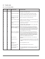
1.9 Motors and solenoids
No.
Part name
Control signal
Function operation
1
Toner motor
TM
Supplies toner
2
Mirror motor
MRMT
Drives the optical mirror base
(scanner unit)
3
Cooling fan motor
VFM
Cools the optical section
4
Main motor
MM
Drives the copier
5
Resist roller solenoid
RRS
Resist roller rotation control solenoid
6
Paper feed solenoid
CPFS1
Cassette paper feed solenoid 1
1-10
Service Manual
Y101700-5
1.10 Sensors and switches
No.
Name
Signal
Type
Function
Output
1
Mirror home
position sensor
MHPS
Transmission sensor
Mirror (scanner unit)
home pos. detection
“H” at home pos.
2
POD sensor
POD
Transmission sensor
Paper exit detection
“H” at paper pass
3
SPPD sensor
SPPD
Transmission sensor
Paper transport detection
“L” at paper pass
4
PPD2 sensor
PPD2
Transmission sensor
Paper transp. detection 2
“L” at paper pass
5
Cassette detect.
switch
CED1
Microswitch
Cassette installation
installation
“H” at cass. insert.
6
PPD1 sensor
PPD1
Transmission sensor
Paper transp. detection 1
“L” at paper pass
7
PPD3 sensor
PPD3
Transmission sensor
Paper transp. detection 3
“L” at paper pass
8
Door switch
DSW
Microswitch
Door open/close detect.
(safety switch for 5V)
1 or 0V or 5V at
door open
9
Door switch
DSW
Microswitch
Door open/close detect.
(safety switch for 24V)
1 or 0V or 24Vat
door open
Y101700-5
Service Manual
1-11
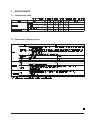
1.11 PWB unit
No.
Name
Function
1
Exposure lamp invertor PWB
Exposure lamp (Xenon lamp) control
2
GDI PWB
For GDI interface
3
Main PWB (MCU)
Copier control
4
Memory PWB 4MB
For memorizing data
5
LSU PWB
For laser control
6
LSU motor PWB
For polygon motor drive
7
TCS PWB
For toner sensor control
8
Operation PWB
Operation input/display
9
CCD sensor PWB
For image scanning
10
Power PWB
AC power input, DC voltage control, High voltage control
1-12
Service Manual
Y101700-5
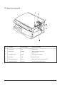
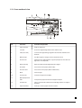
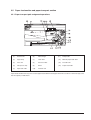
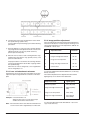
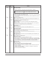
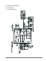
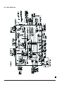
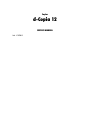
1.12 Cross sectional view
No.
Part name
Function and operation
1
Paper exit roller
Roller for paper exit
2
Lens unit
Scans the original image with the lens and the CCD
3
LSU (Laser unit)
Converts the original image signal into laser beams and writes onto
the drum
4
Main charger
Provides negative charges evenly to the drum surface
5
Scanner unit
Illuminates the original with the copy lamp and passes the reflected
light to the ens unit (CCD)
6
Exposure lamp
Exposure lamp (Xenon lamp) Illuminates original
7
Heat roller
Fuses toner on the paper (Teflon roller)
8
Pressure roller
Fuses toner on the paper (Silicon rubber roller)
9
Drum
Forms images
10
Transfer unit
Transfers images onto the drum.
11
Manual paper feed
roller
Transport the paper from the manual paper feed port
12
PS roller unit
Takes synchronization between the lead edge and the rear edge of
the paper
13
Paper feed roller
Picks up a sheet of paper from the cassette
Y101700-5
Service Manual
1-13
1-14
Service Manual
Y101700-5
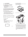
2. UNPACKING AND
INSTALLATION
2.1 Copier installation
Improper installation may damage the copier. Please
note the following during initial installation and whenever
the copier is moved.
Caution: If the copier is moved from a cool place to a
warm place, condensation may form inside the
copier. Operation in this condition will cause
poor copy quality and malfunctions. Leave the
copier at room temperature for at least 2 hours
before use.
2.2 Cautions on handling
Be careful in handling the copier as follows to maintain the
performance of this copier.
Do not drop the copier, subject it to shock or strike it
against any object.
Do not install your copier in areas that are:
• damp, humid, or very dusty
• exposed to direct sunlight
Do not expose the drum cartridge to direct sunlight.
Doing so will damage the surface (green portion) of the
drum cartridge, causing poor print quality.
• poorly ventilated
Store spare supplies such as drum cartridges and TD
cartridges in a dark place without removing from the package
before use.
• subject to extreme temperature or humidity
changes, e.g., near an air conditioner or heater.
If they are exposed to direct sunlight, poor print quality
may result.
Do not touch the surface (green portion) of the drum
cartridge.
Doing so will damage the surface of the cartridge, causing poor print quality.
The copier should be installed near an accessible
power outlet for easy connection. Be sure to connect the
power cord only to a power outlet that meets the specified
voltage and current requirements. Also make certain the
outlet is properly grounded.
Be sure to allow the required space around the machine for servicing and proper ventilation.
Y101700-5
Service Manual
2-1
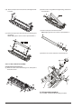
2) Use a coin (or suitable object) to remove the screw.
Store the screw in the paper tray because it will be used if
the copier has to be moved.
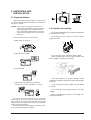
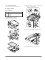
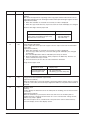
2.3 Checking packed components and
accessories
Open the carton and check if the following components
and accessories are included.
Power cord
Interface
cable
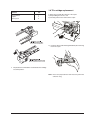
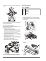
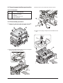
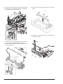
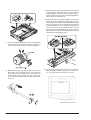
2.6 Developer unit installation
Copier
Drum cartridge
(installed in copier)
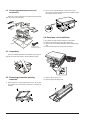
1) 2) 3) Open the side and front cabinets of the copier.
4) Remove the locking tape of the developer unit.
5) Remove the screw which is fixing the copier and Developer
unit.
6) Remove Developer unit slowly from the copier.
2.4 Unpacking
Be sure to hold the handles on both sides of the copier to
unpack the copier and carry it to the installation location.
2.5 Removing protective packing
materials
7) Remove the screw (1 pc).
8) Remove Upper developer unit.
1) Remove pieces of tape and protective cover. Then open
the original cover and remove protective materials (a)
and (b).
2-2
Service Manual
Y101700-5
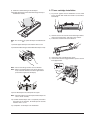
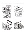
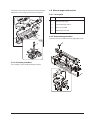
9) Shake the aluminum bag to stir developer.
10) Supply developer from the aluminum bag to the top of
the MX roller evenly.
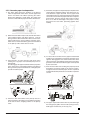
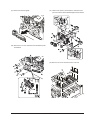
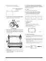
2.7 Toner cartridge installation
1) To prevent against uneven distribution of toner, hold
Toner unit with both hands and shake it several times
horizontally.
2) Hold the section of Toner unit shown in the figure below,
remove the packing tape, and remove the cushion.
3) Pull out the cushion in the arrow direction.
Note: Be careful not to splash developer outside Developer
unit.
11) Attach Upper developer unit and fix it with a screw.
12) Rotate the MG roller gear to distribute developer evenly.
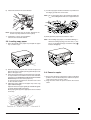
4) Insert Toner unit carefully into the copier.
5) Insert until the hook is engaged with the copier as shown
in the figure below.
Note: Never rotate the gear in the reverse direction.
Note: When carrying Developer unit, do not tilt it extremely as shown with the arrow in the figure below.
(Prevention of splash of developer)
13) Insert Developer unit carefully into the copier.
Note: Quick insertion may result in splash of developer. Be
sure to insert carefully.
14) Confirm that Developer unit is completely inserted to
the bottom of the machine, fix Developer unit and the
machine with a screw.
15) Completion of Developer unit installation.
Y101700-5
Service Manual
2-3
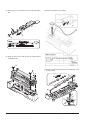
5) Fan the copy paper and insert it into the tray. Make sure
the edges go under the corner hooks.
6) Pull out the shutter in the arrow direction.
Note: Do not load paper above the maximum height line
(
). Exceeding the line will cause a paper misfeed.
Note: Do not hold and carry the shutter. Otherwise the
shutter may drop and Toner unit may drop.
7) Completion of Toner unit installation
Close the front and side cabinets.
6) Gently push the paper tray back into the copier.
2.8 Loading copy paper
1) Raise the handle of the paper tray and pull the paper
tray out until it stops.
2) Remove the pressure plate lock. Rotate the pressure
plate lock to remove it while pressing down the pressure
plate of the paper tray.
3) Store the pressure plate lock which has been removed
in step 2 and the screw which has been removed when
unpacking (see REMOVING PROTECTIVE PACKING
MATERIALS) in the front of the paper tray.
To store the pressure plate lock, rotate the lock to fix it
on the relevant location.
4) Adjust the paper guides on the paper tray to the copy
paper width and length.
Squeeze the lever of paper guide (A) and slide the guide
to match with the width of the paper.
Move paper guide (B) to the appropriate slot as marked
on the tray.
2-4
Note: After loading copy paper, to cancel the blinking “P”
without restarting copying, press the clear (>) key.
The “P” in the display will go out and the ready ( )
indicator will light up.
2.9 Power to copier
1) Ensure that the power switch of the copier is in the OFF
position. Insert the attached power cord into the power
cord socket at the rear of the copier.
2) Plug the other end of the power cord into the nearest
outlet.
Service Manual
Y101700-5
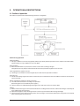
3.
OPERATIONAL DESCRIPTIONS
3.1 Outline of operation
The outline of operation is described referring to the basic configuration.
Outline of copy operation
Setting conditions
1) Set copy conditions such as the copy quantity and the copy density with the operation section, and press the COPY button.
The information on copy conditions is sent to the MCU.
Image scanning
2) When the COPY button is pressed, the scanner section starts scanning of images.
The light from the copy lamp is reflected by the document and passed through the lens to the CCD.
Photo signal/Electric signal conversion
3) The image is converted into electrical signals by the CCD circuit and passed to the MCU.
Image process
4) The document image signal sent from the CCD circuit is processed under the revised conditions and sent to the LSU (laser
unit) as print data.
Electric signal/Photo signal (laser beam) conversion
5) The LSU emits laser beams according to the print data.
(Electrical signals are converted into photo signals.)
6) The laser beams are radiated through the polygon mirror and various lenses to the OPC drum.
Printing
7) Electrostatic latent images are formed on the OPC drum according to the laser beams, and the latent images are developed
to be visible images (toner images).
8) Meanwhile the paper is fed to the image transfer section in synchronization with the image lead edge.
9) After the transfer of toner images onto the paper, the toner images are fused to the paper by the fusing section. The copied
paper is discharged onto the exit tray.
Y101700-5
Service Manual
3-1
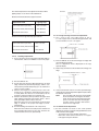
3.2 Scanner section
3.2.1 How to scan documents
The scanner has sensors that are arranged in a line.
These sensors scan a certain area of a document at a time
and deliver outputs sequentially. When the line is finished, the
next line is scanned, and this procedure is repeated.
The figure on the side shows the case where the latter
two sections of an image which are scanned are shown
with solid lines and the former two sections which are being
transmitted are shown with dotted lines.
The direction of this line is called “main scanning direction,” and the scanning direction “sub scanning direction.”
With reference to the figure, one line is divided into 4
sections. Actually, however, one line is divided into thousands of sections. For scanning, the light receiving element
called CCD is used.
The basic resolution indicates the scanner capacity. The
basic resolution is expressed in dpi (dot/inch) which shows
the number of light emitting elements per inch on the document.
The basic resolution of this machine is 400dpi.
In the sub scanning direction, at the same time, the motor
that drives the optical system is controlled to scan the image
at the basic resolution.
3.2.2 Basic structure of scanner section
1
Copy lamp (Xenon lamp)
2
Reflector (light conversion plate)
3
No. 1 mirror
4
No. 2 mirror
5
No. 3 mirror
6
Lens
7
No. 2/3 mirror unit
8
Copy lamp unit
9
CCD
10
Mirror motor
11
MHPS (Mirror home position sensor)
The scanner unit performs scanning in the digital optical system. The light from the light source (Xenon lamp) is reflected by
a document and passed through three mirrors and reduction lenses to the CCD element (image sensor) where images are
formed. This system is known as the reduction image sensor system. Photo energy on the CCD element is converted into
electrical signals (analog signals). (Photo-electric conversion). The output signals (analog signals) are converted into digital
signals (A/D conversion) and passed to the MCU (main control/image process section). The resolution at that time is 400dpi.
The mirror unit in the scanner section is driven by the mirror motor. The MHPS is provided to detect the home position of the copy
lamp unit.
3-2
Service Manual
Y101700-5
3.3 Laser unit
The image data sent from the MCU (image process
circuit) is sent to the LSU (laser unit), where it is converted
into laser beams.
Makes the laser scanning speeds at both ends of the drum
same as each other.
3.3.1 Basic structure
The LSU unit is the writing section of the digital optical
system. The semiconductor laser is used as the light source,
and images are formed on the OPC drum by the polygon
mirror and fθ lens, etc. The laser beams are passed through
the collimator lens, the cylindrical lens, the polygon mirror,
the fθ lens, and the mirror to form images on the OPC drum
in the main scanning direction. The laser emitting PWB is
provided with the APC (auto power control) in order to
eliminate fluctuations in the laser power. The BF PWB
works for measurement of the laser writing start point.
3.3.2 Laser beam path
Laser beam
path for BF PWB
No.
Component
(1)
(2)
Semiconductor laser
Collimator lens
(3)
(4)
(5)
Function
Generates laser beams.
Converges laser beams in
parallel.
Polygon mirror,
Reflects laser beams at a
polygon motor
constant rpm.
BD (Mirror, lens, PWB) Detects start timing
of laser scanning.
fθ lens
Converges laser beams at
a spot on the drum.
Makes the laser scanning
speeds at both ends of
the drum same as each
other (refer to the
figure below).
Y101700-5
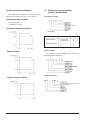
3.3.3 Composition
Effective scanning width:
Resolution:
Beam diameter:
Image surface power:
Polygon motor section:
Service Manual
216mm (max.)
600dpi
75um in the main scanning
direction, 80um in the sub
scanning direction
0.20 ±0.03mW (Laser
wavelength780 – 795nm)
Brushless motor 20.787rpm
No. of mirror surfaces: 6
surfaces
3-3
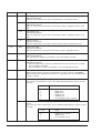
(3) Thermal control
1. The heater lamp, thermistor, main PWB, DC power
supply PWB, and triac within the power supply unit are
used to control the temperature in the fuser unit.
To prevent against abnormally high temperature in the
fuser unit, a thermal breaker and thermal fuse are used for
safety purposes.
3.4 Fuser section
Heated by the heater
lamp (950 W)
Safety device (thermal
breaker, thermal fuse)
3.4.1 General description
The surface temperature
of the upper heat roller is
sensed by the termistor.
General block diagram (cross section)
Triac (in the power
supply unit)
Level of the thermistor
is controlled by the
main PWB
With the signal from the
main PWB, the triac is
controlled on and off
(power supply PWB)
2. The surface temperature of the upper heat roller is set
to 165°C ~ 190°C. The surface temperature during the
power save mode is set to 100°C.
(1) Heat roller
A Teflon roller is used for the heat roller and a silicone
rubber roller is used for the lower heat roller for better toner
fusing performance and paper separation.
(2) Separator pawl
Three separator pawls are used on the upper heat roller. The
separator pawls are teflon coated to reduce friction with the
roller and prevent a smear on the paper caused by the
separator pawl.
3-4
3. The self-check function comes active when one of the
following malfunctions occurs, and an “H” is displayed on
the multicopy window.
a. When the heat roller surface temperature rises above
240°C.
b. When the heat roller surface temperature drops below
100°C during the copy cycle.
c. Open thermistor
d. Open thermal fuse
e. When the heat roller temperature does not reach
190°C within 27 second after supplying the power.
(4) Fusing resistor
Fusing resistor
This model is provided with a fusing resistor in the fusing
section to improve transfer efficiency.
General descriptions are made in the following.
General descriptions
Since the upper heat roller is conductive when copy paper is
highly moist and the distance between the transfer unit and
the fusing unit is short, the transfer current leaks through the
copy paper, the upper heat roller and the discharging brush.
Service Manual
Y101700-5
3.5 Paper feed section and paper transport section
3.5.1 Paper transport path and general operations
(1)
Scanner unit
(6)
Main charger
(11)
Pickup roller
(2)
Copy lamp
(7)
Heat roller
(12)
Manual paper feed roller
(3)
Lens unit
(8)
Pressure roller
(13)
PS roller unit
(4)
LSU (Laser unit)
(9)
Drum
(14)
Paper feed roller
(5)
Paper exit roller
(10)
Transfer unit
Paper feed is made in two ways; the cassette paper feed and the manual paper feed. The cassette is of universal-type, and
has the capacity of 250 sheets.
Y101700-5
Service Manual
3-5
3.5.2 Cassette paper feed operation
1) The figure below shows the positions of the pick-up
roller, the paperfeed clutch sleeve, and the paper feed
latch in the initial state without pressing the COPY
button after lighting the ready lamp. The paper feed
latch is in contact with the projection of the clutch sleeve.
5) At this time, the paper is fed past the paper entry detection
switch (PPD1), and detected by it. After about 0.15 sec
from detection of paper by PPD1, the tray paper feed
solenoid (PFS) turns on so that the clutch sleeve projection
comes into contact with the paper feed latch to stop the
pick-up roller. Then the pick-up roller rotates for about
0.15 sec so that the lead edge of the paper is evenly
pressed on the resist roller, preventing against skew
feeding.
2) When the COPY button is pressed, the main drive motor
starts rotating to drive each drive gear.The pick-up
drive gear also is driven at that time. Since, however, the
paper feed latch is in contact with the projection of the
clutch sleeve, rotation of the drive gear is not transmitted
to the pick-up roller, which does not rotate.
3) After about 0.1 sec from when the main motor starts
rotating, the tray paper feed solenoid (PFS) turns on
momentarily.
This disengages the paper feed latch from the projection
of the clutch sleeve, transmitting rotation of the pick-up
drive gear to the paper feed roller shaft, rotating the pickup roller to feed the paper.
4) After more than half rotation of the pick-up roller, the
paper feed latch is brought in contact with the projection
of the clutch sleeve, stopping rotation of the pick-up
roller.
3-6
6) To release the resist roller, the tray paper feed solenoid
and the resist solenoid are turned on by the paper start
signal to disengage the resist start latch from the clutch
sleeve projection, transmitting rotation of the resist drive
gear to the resist roller shaft. Thus the paper is transported
by the resist roller.
7) After the resist roller starts rotating, the paper is passed
through the pre-transfer guide to the transfer section.
Images are transferred on the paper, which is separated
from the OPC drum by the drum curve and the separation
section.
8) The paper separated from the drum is passed through
the fusing paper guide, the heat roller (fusing section),
POD (paper out detector) to the copy tray.
Service Manual
Y101700-5
4. DISASSEMBLY AND ASSEMBLY
Before disassembly, be sure to disconnect the power cord
for safety.
The disassembly and assembly procedures are described
for the followingn sections:
1. High voltage section
2. Operation panel section
3. Optical section
4. Fusing section
5. Cassette paper feed/transport section
6. Manual paper feed section
7. Rear frame section
8. Power section
2) Remove the drum fixing plate and the photoconductor
drum.
Note: Dispose the drum fixing plate which was removed.
4.1 High voltage section
4.1.1 List of parts
No.
Part name Ref.
1
2
3
Drum
Transfer charger unit
Charger wire
4.1.2 Drum replacement
1) Remove the drum cover. (4 Lock Tabs)
Y101700-5
3) Check the cleaning blade and the red felt for no damage.
• If there is any damage, execute all procedures from
item 5) and later.
• If there is no damage, execute the procedure of item 12).
4) Remove the main charger.
(Cleaning the screen grid and the sawteeth.)
Service Manual
4-1
5) Remove the cleaning blade.
Note: Dispose the cleaning blade which was removed.
6) Clean the cleaning section and the waste toner pipe to
remove waste toner completely with a vacuum cleaner.
7) Remove the felt and duplex tape completely.
Note: Be careful not to scratch or bend the sub blade.
8) Attach the cleaning blade.
Securely insert the plate section of the cleaning blade into
the unit and fix it with a screw.
Do not touch the cleaning blade rubber with your hand.
When attaching the cleaning blade, press the cleaning
blade in the arrow direction and attach.
Attach the mocket with slightly pressing the cleaning blade.
Do not touch the tip of the cleaning blade.
Do not put the mocket under the cleaning blade.
Do not put the mocket on the sub blade.
Do not press the sub blade with the mocket.
10) Attach the main charger.
Securely set the MC holder on the projection of the
process frame.
Securely insert two projections of the MC holder into the
groove in the process frame.
When attaching the MC holder ass’y, be careful not to
make contact with the cleaning blade.
11) Attach the drum fixing plate and the photoconductor
drum.
Apply grease to the inside of the photoconductor drum.
9) Attach the felt.
Attach the drum. (Prevention against the sub blade edge
breakage)
Attach the drum so that its position with the sub blade is as
shown.
12) Attach the drum cover.
4-2
Service Manual
Y101700-5
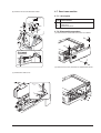
(2) Push up the lock pawls (2 positions) of the side cover,
and remove the transfer charger.
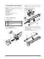
4.1.3 Disassembly procedure
(1) Press the side cover open/close button and open the side
cover.
4.1.4 Assembly procedure
For assembly, reverse the disassembly procedure.
4.1.5 Charger wire cleaning
(1) Remove the charger cleaner from the manual paper
feed unit.
Y101700-5
Service Manual
4-3
(2) Set the charger cleaner to the transfer unit, and move it
reciprocally a few times in the arrow direction shown in
the figure below.
4.2 Operation panel section
4.2.1 List of parts
No.
Part name Ref.
1
2
Operation panel unit
Operation PWB
4.2.2 Disassembly procedure
(1) Remove the screws (4 pcs.), the harness, and the
operation panel unit.
4.1.6 Charger wire replacement
(1) Remove the TC cover and remove the screw.
(2) Remove the spring and remove the charger wire.
(3) Install a new charger wire by reversing the procedures
(1) and (2).
At that time, be careful of the following items.
• The rest of the charger wire must be within 1.5mm.
• The spring hook section (charger wire winding section)
must be in the range of the projection section.
• Be careful not to twist the charger wire.
4-4
(2) Remove the screws (3 pcs.) and the PWB holder.
(3) Remove the screws (3 pcs.) and the operation PWB.
Service Manual
Y101700-5
4.2.3 Assembly procedure
(2) Remove the screws (2pcs.), and remove the copy lamp
unit from the mirror base drive wire.
For assembly, reverse the disassembly procedure.
4.3 Optical section
4.3.1 List of parts
No.
1
2
3
Part name Ref.
Copy lamp unit
Copy lamp
Lens unit
4.3.2 Disassembly procedure
(1) Remove the parts as shown below.
(3) Pull the copy lamp unit toward you to remove the harness.
(4) Remove the screw (4 pc) and remove the cover.
Y101700-5
Service Manual
4-5
(5) Remove the screws (2 pcs.), the harness, and the optical
unit.
4.4 Fusing section
4.4.1 List of parts
No.
1
2
3
4
5
Part name Ref.
Thermistor
PPD2 sensor
Heater lamp
Pressure roller
Heat roller
4.4.2 Disassembly procedure
(1) Remove the connectors (3 pcs.) of the rear cabinet.
(2) Open the side cover, remove two screws, and remove
the fusing unit.
When installing the lens unit, refer to “Lens unit installation
reference” in the next chapter.
4.3.3 Assembly procedure
Basically reverse the disassembly procedure.
The mirror base drive wire and the lens drive wire stretching
methods are described below.
a. Mirror base drive wire stretching
1. Hook the metal fixture of the mirror base drive wire on
the projection of the optical base plate.
2. Pass the wire through the external groove of the double
pulley. (At that time, check that No. 2/3 mirror unit is in
contact with the mirror base positioning plate.)
3. Hold so that the winding pulley groove is up, and wind the
mirror base drive wire 9 turns.
4. Put the 8th turn of the mirror base drive wire in the winding
pulley groove and fix with a screw.
5. Pass the wire under No. 2/3 mirror unit plate and wind it
around the pulley.
6. Pass the wire through the internal groove of the double
pulley and pass through the pulley.
7. Hook the spring hook on the optical base plate.
(3) Cut the binding band, remove the screw, and remove the
thermistor.
After installing the mirror base drive wire, be sure to
perform main scanning direction image distortion adjustment.
4-6
Service Manual
Y101700-5
(7) Remove the plate spring on the right and remove the
heater lamp.
(4) Remove the screw and remove the U-turn guide.
4.4.2.1 Pressure roller section disassembly
(5) Remove the three screws, remove the fusing cover lower
on the right side, and open the heat roller section.
(8) Remove the spring and remove the separation pawls
(3 pcs).
(6) Remove the screw and remove the PPD2 sensor.
(9) Remove the E-ring and remove the reverse gate.
Y101700-5
Service Manual
4-7
(10) Remove the pressure release levers on the right and the
left sides.
(6) Remove the C-ring and the fusing bearing, and remove
the heat roller.
(7) Remove the parts from the heat roller.
Note: Apply grease to the sections specified with
(11) Remove the pressure roller, the pressure bearing, and
the spring.
Note: Apply grease to the sections specified with .
*.
*
(8) Remove two screws and remove the thermostat.
4.4.2.2 Heat roller disassembly
Continued from procedure (4).
(5) Remove screws, remove the fusing cover, and open the
heat roller section.
4.4.3 Assembly procedure
For assembly, reverse the disassembly procedure.
4-8
Service Manual
Y101700-5
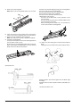
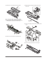
4.5 Cassette paper feed/transport section
(3) Remove two screws and remove the toner motor.
4.5.1 List of parts
No.
1
2
3
4
Part name Ref.
PPD1 sensor PWB
LSU unit
Intermediate frame unit
Paper feed roller
4.5.2 Disassembly procedure
(1) Remove six connectors and screws of the main PWB,
and lift the optical unit and the main PWB to remove.
(4) Remove two springs and open the intermediate frame
unit.
(2) Remove the PWB insulation mylar and remove the paper
transport detection sensor (PPD2).
Y101700-5
Service Manual
4-9
(5) Remove the pulleys on the both sides and remove the
paper exit roller.
(7) Release the belt pulley lock and remove the belt pulley
bearing.
(6) Pull out the paper exit roller knob and remove the belt.
(8) Remove the paper exit roller.
4-10
Service Manual
Y101700-5
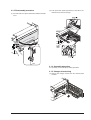
(9) Remove the harness guide.
(11) Remove the parts as shown below, and remove the
pressure release solenoid and the paper feed solenoid.
(10) Remove five screws and remove the main drive plate
and the belt.
(12) Remove six screws and remove the LSU unit.
Y101700-5
Service Manual
4-11
(13) Remove two screws and remove the fusing connector.
(14) Remove five screws and the connector, and lift the
intermediate frame unit to remove.
(17) Remove three screws and remove the TC front paper
guide.
(18) Remove the screw and the connector, and remove the
PPD1 sensor PWB.
(15) Remove the screw and the E-ring, and remove the PS
semi-circular earth plate and the PS roller unit.
(16) Remove the E-ring and remove the spring clutch from
the PS roller unit.
4-12
Service Manual
Y101700-5
(19) Remove two E-rings and remove the paper feed roller.
(20) Remove three E-rings and remove the clutch unit.
4.6 Manual paper feed section
4.6.1 List of parts
No.
Part name Ref.
1
Manual transport roller
2
Cassette detection switch
3
PPD1 sensor PWB
4
Side door detection unit
4.6.2 Disassembly procedure
(1) Remove the screw and remove the single upper cover.
4.5.3 Assembly procedure
For assembly, reverse the disassembly procedure.
Y101700-5
Service Manual
4-13
(2) Remove the screw and remove the side door detection
unit.
(4) Remove the PPD1 sensor PWB.
(3) Remove three screws and remove the single manual
feed upper frame.
(5) Remove the E-ring and remove the manual paper feed
transport roller.
4-14
Service Manual
Y101700-5
(6) Remove the cassette detection switch.
4.7 Rear frame section
4.7.1 List of parts
No.
Part name Ref.
1
2
3
Mirror motor
Main motor
Exhaust fan motor
4.7.2 Disassembly procedure
(1) Remove three screws and remove the rear cabinet.
(2) Remove two screws, the harness, and the mirror motor.
(7) Remove the multi cover.
Y101700-5
Service Manual
4-15
(3) Remove two screws and one harness, and remove the
main motor.
4.8 Power section
4.8.1 List of parts
No.
1
Part name Ref.
Power PWB
4.8.2 Disassembly procedure
(1) Remove two screws and one connector, and remove the
power PWB.
(4) Remove two screws and one connector, and remove the
exhaust fan motor.
4.8.3 Assembly procedure
For assembly, reverse the disassembly procedure.
4.7.3 Assembly procedure
For assembly, reverse the disassembly procedure.
4-16
Service Manual
Y101700-5
5.
5.1.1.3 Adjustment procedure
1) Remove the right cabinet (manual paper feed unit), the
document reference plate.
2) Remove the document glass.
ADJUSTMENTS
5.1 Image distortion adjustment
There are following two types of image distortion.
• Horizontal image distortion
• Vertical image distortion
In this machine, the image distortion is adjusted by
changing the parallelism of mirrors (copy lamp unit,
No. 2/3 mirror unit).
5.1.1 Horizontal image distortion adjustment
Parallelism of mirrors can be made by installing the copy
lamp unit and No. 2/3 mirror unit to the reference position.
However, it must be checked by making a copy, and
must be adjusted if necessary.
5.1.1.1 Cases when the adjustment is required
1) When the copy lamp unit and No.2/3 mirror unit are
disassembled or their part is replaced.
2) When the copy lamp unit and No.2/3 mirror unit drive
section is disassembled or its part is replaced.
3) When the copy image is distorted as shown below:
3) Loosen the fixing screw of the copy lamp unit wire.
5.1.1.2 Necessary tools
• Screwdriver (+)
• Hex wrench
• Scale
• Test chart for distortion adjustment (Make a chart
shown below by yourself.)
Draw a rectangle on a paper (B4 or 8 1/2” x 14”)
as shown below.
Be sure to make four right angles.
4) Manually turn the copy lamp unit/No.2/3 mirror unit drive
gear to bring No.2/3 mirror unit into contact with No.2/3
mirror unit positioning plate. When No.2/3 mirror unit
makes contact with No.2/3 mirror unit positioning plate in
the Freat and rear frameside simultaneously, the
mechanical parallelism of No.2/3 mirror unit is proper.
If one side of No.2/3 mirror unit makes contact with
No. 2/3 mirror unit positioning plate and the other side
does not, the parallelism is improper.
If the parallelism is improper, perform the procedure of
step 5.
Y101700-5
Service Manual
5-1
7) Manually turn the copy lamp unit/No.2/3 mirror unit drive
gear to bring No.2/3 mirror unit into contact with the
positioning plate, and perform the procedure of step 4.
Repeat procedures of steps 4 to 7 until the parallelism of
No.2/3 mirror unit is properly set.
8) With No.2/3 mirror unit positioning plate in contact with
No.2/3 mirror unit, bring the copy lamp unit into contact
with the right frame and fix the copy lamp unit to the drive
wire. Procedures 1 to 8 are for adjustment of mechanical
horizontal parallelism. The copy lamp unit and No.2/3
mirror are fixed to the specified positions and the
mechanical horizontal parallelism of No.2/3 mirror is
adjusted. Then the optical horizontal parallelism must be
adjusted in the following procedures.
5) Loosen the copy lamp unit/No.2/3 mirror unit drive pulley
setscrew in the side where No.2/3 mirror unit does not
make contact with No.2/3 mirror unit positioning plate.
6) Without moving the copy lamp unit/No.2/3 mirror unit
drive pulley shaft, manually turn the copy lamp unit/
No.2/3 mirror unit drive pulley in the same direction of
the loosened setscrew. When it makes contact with
No.2/3 mirror unit positioning plate, tighten and fix the
setscrew.
5-2
9) Set the image distortion check chart on the document
table, and make a reduction copy (75%) on an A4 or 11”
x 8 1/2” paper with the document cover open.
Service Manual
Y101700-5
10) Check the horizontal image distortion.
If LL = LR, there is no horizontal distortion
5.1.2 Vertical image distortion adjustment
In this adjustment, the left and right balance is adjusted by
changing the left and right balance of the No. 2 scanner unit
frame on the front frame side.
5.1.2.1 Note
• Horizontal image distortion adjustment
5.1.2.2 Cases when the adjustment is required
1) When the copy lamp unit/No.2/3 mirror unit drive
section is disassembled or its part is replaced.
2) When the copy image is distorted as follows:
11) If LL is not equal to LR, perform the following procedure.
Loosen the setscrew of the copy lamp unit/No.2/3 mirror
unit drive pulley in the front or the rear frame.
5.1.2.3 Necessary tools
• Screwdriver (+)
• Screwdriver (–)
• Scale
• Test chart for distortion adjustment (Make
yourself). Draw a rectangle on A4 or 8 1/2” x 11”
paper as shown below:
Be sure to make four right angles.
12) Without moving the copy lamp unit/No.2/3 mirror unit
drive pulley shaft, manually turn the copy lamp unit/
No.2/3 mirror unit drive pulley whose setscrew was
loosened, and adjust the parallelism of copy lamp unit/
No.2/3 mirror unit.
5.1.2.4 Adjustment procedure
1) Set the test chart for image distortion adjustment on the
document glass, and make a normal copy on a paper of
A4 or 8 1/2” x 11”.
2) Check image distortion in the right and the left sides.If the
both vertical lines are in parallel with each other, the
rightleft distortion balance is proper. (However, there
may be some distortion).
If all the four angles are right angles, there in no distortion
and the following procedures are not required.
13) Tighten the set screw of the copy lamp unit/No.2/3 mirror
unit drive pulley.
14) Check the image distortion in the same manner as step
10. Repeat procedures 11 to 14 until horizontal image
distortion is eliminated.
Y101700-5
Service Manual
5-3
3) If the right-left distortion balance is improper, loosen the
fixing screw of No.2/3 mirror unit rail to change and adjust
the right-left balance of No.2/3 mirror unit rail.
The main scanning (front/rear) direction magnification ratio
adjustment is made automatically or manually.
Automatic adjustment: The width of the reference line marked
on the shading correction plate is scanned to perform the
main scanning (front/rear) direction magnification ratio adjustment automatically.
Manual adjustment: The adjustment is made by manual key
operations. (In either of the automatic and manual adjustments, the zoom data register set value is changed for adjustment). The magnification ratio in the sub scanning direction is
adjusted by changing the mirror base (scanner) scanning
speed.
5.2.1 Main scanning direction magnification
ratio adjustment
Note:
If the distortion in the lead edge side (when viewed in the
paper transport direction) is greater, change the height of
the left rail of No.2/3 mirror unit.
If the distortion in the rear edge side (when viewed in the
paper transport direction) is greater, change the height of
the right rail of No.2/3 mirror unit.
Before performing this adjustment, the following adjustments
must have been completed. If not, this adjustment cannot be
performed properly.
• Image distortion adjustment
• The lens unit must be installed in the reference position.
5.2.1.1 Cases when the adjustment is required
1) When the lens and the mirror unit are disassembled or the
part is replaced.
2) When the copy lamp unit/No.2/3 mirror unit drive section
is disassembled
or the part is replaced.
3) When the main PWB is replaced.
4) When the EEPROM in the main PWB is replaced.
5) When “U2” trouble occurs.
6) When the copy image distortion adjustment is performed.
5.2.1.2 Necessary tools
• Screwdriver (+)
• Scale
5.2.1.3 Adjustment procedure
1) Set the scale vertically on the document table. (Use a
long scale for precise adjustment.)
4) Make a copy to check the vertical image distortion.
If the four angles are right angles, the adjustment is
completed.
5.2 Copy magnification ratio adjustment
The copy magnification ratio must be adjusted in the main
scanning direction and in the sub scanning direction.
To adjust, use SIM 48-1.
2) Set the copy magnification ratio to 100%.
3) Make a copy on A4 or 81/2” x 11” paper.
5-4
Service Manual
Y101700-5
4) Measure the length of the copied scale image.
5) Calculate the main scanning direction magnification ratio.
Main scanning direction magnification ratio
=
Copy image dimensions
Original dimension
6) Check that the copy magnification ratio is within the
specified range. If it is not within the specified range,
perform the following procedures.
7) Execute SIM 48-1 to select the main scanning direction
copy magnification ratio adjustment mode. To select the
adjustment mode, use the copy mode select key.
In the case of the automatic adjustment, when the PRINT
switch is pressed, the mirror base unit moves to the white
plate for shading to scan the width of the reference line,
calculating the correction value and displaying and storing
this value.
After execution of the automatic adjustment, go out from
the simulation mode and make a copy to check the
magnification ratio. If the magnification ratio is not in the
specified range (100 ±1.0%), manually adjust as follows.
Adjustment mode
× 100 (%)
5.2.2.1 Cases when the adjustment is required
1) When the lens and the mirror unit are disassembled or the
part is replaced.
2) When the scanner unit drive section is disassembled or
the part is replaced.
3) When the main PWB is replaced.
4) When the EEPROM in the main PWB is replaced.
5) When “U2” trouble occurs.
6) When the copy image distortion adjustment is performed.
5.2.2.2 Necessary tools
• Screwdriver (+)
• Scale
5.2.2.3 Adjustment procedure
1) Set the scale on the document table as shown below.
(Use a long scale for precise adjustment.)
Lighting lamp
Main scanning direction auto
copy magnification ratio
adjustment
Auto exposure lamp
ON
Main scanning direction manual
copy magnification ratio
Manual exposure lamp
ON
adjustment
Sub scanning direction copy
magnification ratio adjustment
Photo exposure lamp
ON
8) Set the adjustment mode to Manual with the copy mode
select key.
9) Enter the new set value of main scanning direction copy
magnification ratio with the copy quantity set key, and
press the COPY button.
10) Change the set value and repeat the adjustment until the
ratio is within the speoified range.
When the set value is changed by 1, the magnification
ratio is changed by 0.1%.
5.2.2 Sub scanning direction copy
magnification ratio
Before performing this adjustment, the following
adjustments must have been completed. If not, this
adjustment cannot be performed properly.
• Image distortion adjustment
• Must be installed to the lens unit reference position.
Y101700-5
2) Set the copy magnification ratio to 100%.
3) Make a copy on A4 or 81/2” x 11” paper.
4) Measure the length of the copied scale image.
5) Calculate the sub scanning direction copy magnification
ratio.
Copy image dimensions
=
Service Manual
Original dimension
× 100 (%)
5-5
6) Check that the actual copy magnification ratio is within
the specified range. (100 ± 1.0%).
If it is not within the specified range, perform the following
procedures.
5.2.4 Image position adjustment
There are following five kinds of image position adjustments,
which are made by laser control except for the image scan
start position adjustment. For the adjustments, SIM 50 – 01
and SIM 50 – 10 are used.
7) Execute SIM 48-1 to select the sub scanning direction
copy magnification ratio adjustment mode. To select the
adjustment mode, use the copy mode select key.
(Photo exposure lamp ON)
No.
Adjustment item
1
Print start position
50 – 01
8) Enter the new set value of sub scanning direction copy
magnification ratio with the copy quantity set key, and
press the COPY button.
2
Image lead edge void amount
50 – 01
3
Image scan start position
50 – 01
4
Image rear edge void amount
50 – 01
5
Center offset
50 – 10
Repeat procedures 1-8 until the sub scanning direction
actual copy magnification ratio in 100% copying is within
the specified range.
When the set value is changed by 1, the magnification
ratio is changed by 0.1%.
5.2.3 Lens unit attachment reference
Attach the lens unit so that the lens unit number on the lens
adjustment plate is aligned with the scribe line on the base
plate.
To select the adjustment mode with SIM 50 – 01, use the copy
density select key.
The relationship between the adjustment modes and the
lighting lamps are as shown in the table below.
Adjustment mode
Lighting lamp
Print start position
Auto (AE) lamp
Image lead edge void amount
Manual (TEXT)
lamp
Image scan start position
Photo lamp
Image rear edge void amount
Auto, Manual,
Photo lamps
Example: Lens unit number –2.8
Attach the lens unit at 2 scales in the paper
exit direction from the reference line.
Note: Never touch the other screws than the unit attachment
screw. The lens unit is supplied only in a whole unit.
5-6
Simulation
To select the adjustment mode with SIM 50 – 10, use the
copy mode select key.
Service Manual
Y101700-5
The relationship between the adjustment modes and the
lighting lamps are as shown in the table below
Machine with the multi manual paper feed unit.
Adjustment mode
Lighting lamp
Print center offset (cassette)
Auto, Cassette
Print center offset (manual feed)
Auto, Manual
Document center offset
Auto, Manual
5.2.4.2 Image rear edge void amount adjustment
1) Set a scale to the rear edge section of A4 or
11” x 8 1/2” paper size as shown in the figure below, and
cover it with B4 or 8 1/2” x 14” paper.
Machine with the single manual paper feed unit
Print center offset (cassette)
Auto, Cassette
Print center offset (manual feed)
Auto
Document center offset
Auto, Manual
5.2.4.1 Lead edge adjustment
1) Set a scale to the center of the paper lead edge guide as
shown below, and cover it with B4 or 8 1/2” x 14” paper.
2) Execute SIM 50 – 01 to select the image rear edge void
amount adjustment mode.
The set adjustment value is displayed on the copy
quantity display.
3) Make a copy and measure the void amount of image rear
edge.
2) Execute SIM 50 – 01
3) Set the print start position (AE lamp ON) (A), the lead
edge void amount (TEXT lamp ON) (B), and the scan
start position (PHOTO lamp ON) (C) to 0, and make a
copy of a scale at 100%.
4) Measure the image loss amount (R mm) of the scale
image. Set C = 10 x R (mm). (Example: Set the value of
C to 30.) When the value of C is increased by 10, the
image loss is decreased by 1mm. (Default: 50)
5) Measure the distance (H mm) between the paper lead
edge and the image print start position. Set A = 10 x H
(mm). (Example: Set the value of A to 50.)
When the value of A is increased by 10, the image lead
edge is shifted to the paper lead edge by 1mm.
(Default: 50)
6) Set the lead edge void amount to B = 50 (2.5mm).
When the value of B is increased by 10, the void amount
is increased by about 1mm. For 25 or less, however, the
void amount becomes zero. (Default: 50)
Y101700-5
4) If the measurement value is out of the specified range,
change the set value and repeat the adjustment procedure.
The default value is 50.
Note:
The rear edge void cannot be checked with
the first sheet after entering the simulation
mode, the first sheet after turning off/on the
power, or the first sheet after inserting the
cassette. Use the second or later sheet to
check the rear edge void.
5.2.4.3 Center offset adjustment
1) Set the self-made test chart for the center position
adjustment so that its center line is aligned with the center
mark of the document guide.
• Test chart for the center position adjustment
Draw a line at the center of A4 or 8 1/2” x 11” paper
in the paper transport direction.
Service Manual
5-7
5.3.2 Note for copy density adjustment
5.3.2.1 Arrangement before execution of the copy
density adjustment
• Clean the optical section.
• Clean or replace the charger wire.
• Check that the voltage at the high voltage section and
the developing bias voltage are in the specified range.
5.3.3 Necessary tool for copy density
adjustment
2) Execute SIM 50 – 10 to select the print center offset
(cassette paper feed) adjustment mode. The set
adjustment value is displayed on the copy quantity display.
3) Make a copy and check that the copied center line is
properly positioned.
The standard value is 0 ± 2mm from the paper center.
• One of the following test charts:
UKOG-0162FCZZ, UKOG-0089CSZZ, KODAK GRAY
SCALE
• B4 (14” x 8 1/2”) white paper
• The user program AE setting should be “3.”
Test chart comparison table
4) If the measured value is out of the specified range,
change the set value and repeat the adjustment procedure.
When the set value is increased by 1, the copy image is
shifted by 0.1mm toward the rear frame.
• For the manual paper feed, change the manual
paper feed adjustment mode and perform the
similar procedures.
• Since the document center offset is automatically
adjusted by the CCD which scan the reference
lines (F/R) on the back of document guide, there is
no need to adjust manually.
5.3.4 Features of copy density adjustment
For the copy density adjustment, the image data shift function
provided in the image process LSI is used.
List of the adjustment modes.
Auto Mode
Manual Mode
Brightness 1 step only
Brightness 5 steps. Adjustment of
only the center brightness is made.
5.3 Copy density adjustment
Photo Mode
only the center brightness is made.
5.3.1 Copy density adjustment timing
The copy density adjustment must be performed in the
following cases:
• When maintenance is performed.
• When the developing bias/grid bias voltage is adjusted.
• When the optical section is cleaned.
• When a part in the optical section is replaced.
• When the optical section is disassembled.
• When the OPC drum is replaced.
• When the main control PWB is replaced.
• When the EEPROM on the main control PWB is
replaced.
• When the memory trouble (U2) occurs.
5-8
Brightness 5 steps. Adjustment of
Manual T/S
Brightness 5 steps. Adjustment
of only the mode
center brightness is made.
T/S Auto mode
Service Manual
Brightness 1 step only
Y101700-5
5.3.5 Copy density adjustment procedure
Use SIM 46-01 to set the copy density for each copy mode.
For selection of modes, use the copy mode select key.
5.3.5.1 Test chart (UKOG-0162FCZZ) setting
1) Place the test chart so that its edge is aligned with the
A4 (Letter) reference line on the document table. Then
place a B4 (14” x 8 1/2”) white paper on the test chart
and close the document cover.
3) Make a copy.
Check the adjustment level (shown in the above table) of
the exposure test chart (Gray Scale).
5.3.5.2 Perform the adjustment in each mode.
1) Execute SIM 46-1.
2) Select the mode to be adjusted with the exposure mode
select key. Set the exposure level to 3 for all adjustment.
(Except for the auto mode.)
(When too bright): Decrease the value displayed on the
copy quantity display.
(When too dark): Increase the value displayed on the
copy quantity display.
* The value can be set in the range of 1 - 99.
Y101700-5
Service Manual
5-9
5.4 High voltage adjustment
5.4.2 DV bias adjustment
5.4.1 Main charger (Grid bias)
• A digital multi meter with internal resistance of 1GW
must be used for correct adjustment.
• Use a digital multi meter with internal resistance of
10MW or more measurement.
• After adjusting the grid LOW output, adjust the HIGH
output.
Do not reverse the sequence.
5.4.2.1 Procedures
5.4.1.1 Procedures
1. Set the digital multi meter range to DC700V.
2. Set the positive side of the test rod to the connector
CN11-3 (GRID) of high voltage section of the power PWB
and set the negative side to the frame ground (radiating
plate).
3. Execute SIM 8-3. (The main charger output is supplied for
30 sec in the grid voltage LOW output mode.)
4. Adjust the control volume (VR-141) so that the output
voltage is – 400 ±20V.
5. Execute SIM 8-2. (The main charger output is supplied for
30 sec in the grid voltage HIGH output mode.)
6. Adjust the control volume (VR-142) so that the output
voltage is 580 ±10V.
5-10
1. Set the digital multi meter range to DC500V.
2. Set the positive side of the test rod to the connector
CN-10-1 (DV BIAS) and set the negative side to the
connector CN10-2 (FG).
3. Execute SIM 8-1. (The developing bias is outputted for
30 sec.)
4. Adjust the control volume (VR-121) so that the output
voltage is – 400 ±5V.
Service Manual
Y101700-5
6. SIMULATIONS AND TROUBLE CODES
6.1 Simulations
6.1.1 List of simulations
Sim No.
Kind of main code Sub code
Operation
01
Optical system
01
Mirror scan operation
05
Lamp ON
check
01
02
03
Operation panel display check
Fusing lamp ON + Cooling fan HIGH/LOW speed
Copy lamp ON
06
Machine
individual
load
operation
01
02
Paper feed solenoid ON
Resist solenoid ON
07
Aging
01
06
Warm up display and aging with jam
Intermittent aging
08
High
voltage
output check
01
02
03
06
Developing bias
Main charger (Grid high)
Grid Voltage (Low)
Transfer charger.
10
Other
None
Toner motor aging
14
Trouble
reset
None
Cancel troubles other than U2
16
U2 Trouble
reset
None
Cancel of U2 trouble
20
Manteinance
counter clear
01
Manteinance/mini-manteinance
counter clear
21
Counter setup
(When
manteinance)
01
02
Manteinance cycle setup
Mini-manteinance cycle setup
22
Counter
display
01
02
05
06
12
14
Maintenance/mini-maintenance counter display
Maintenance/mini-maintenance preset display
Total counter display
Developer counter display
Drum counter display
P-ROM version display
24
Special counter
clear
06
07
Developer counter clear
Drum counter clear
25
Main motor ON
01
10
Main motor system ON + Cooling fan low speed
Poligon motor ON
Y101700-5
Service Manual
6-1
Sim No.
Kind of main code Sub code
Operation
26
Various setup
01
02
03
04
06
07
20
30
37
39
40
42
43
Manual feed setup
SPF setup
Second cassette setup
Machine duplex setup
Destination setup
Machine conditions check
Rear edge void setup
CE mark conformity control ON/OFF setup
Cancel of stop at developer over
Memory capacity setup
Polygon motor OFF time setup
Transfer ON timing control setup
Side void setup
30
Sensor operation
check (standard
provision)
01
Paper sensor display status
43
Fusing temp.
setup
01
04
Normal copy
Fusing temperature setup 2
46
Exposure
adjustment
01
19
Copy density adjustment
Gamma table adjustment (Copy mode)
48
Magnification
ratio correction
01
Front/rear scan ditrection
50
Lead edge
adjustment
01
10
Lead edge image position adjustment
Paper lead edge/rear edge void adjustment
Paper center offset + OC/Document center offset
51
Timing
adjustment
02
Resist quantity adjustment
61
Laser system
operation
03
Pligon motor check (HSYNC output check)
63
Shading
01
Shading check
64
Self print
01
Self print only with the engine (1 by 2 mode)
6-2
Service Manual
Y101700-5
Main code
01
Content
Sub code
01
Mirror scan operation
(Operation/Procedure)
1. When this simulation is executed, the mirror home position is detected.
Sensor name
Mirror home position sensor
Display lamp
OPC drum cartridge replacement lamp
2. When the _START key is pressed, scanning is executed at the speed corresponding
to the currently set copy magnification ratio.
The copy magnification ratio can be arbitrarily set with the magnification ratio select
key/zoom key.
05
06
07
Y101700-5
01
Operation panel display check
When the PRINT switch is pressed, the LED on the operation panel is lighted for 5 sec.
02
Fusing lamp ON + cooling fan HIGH/LOW speed
(Operation/Procedure)
When the START key is pressed, the fusing lamp repeats ON (500ms) and OFF
(500msec) 5 times.
During this period, the cooling fan rotates in the high speed mode. After completion of
the operation, the cooling fan rotates in the low speed mode.
03
Copy lamp ON
(Operation/Procedure)
When the START key is pressed, the copy lamp is lighted for 5 sec.
01
Paper feed solenoid ON
(Operation/Procedure)
When the START key is pressed, the paper feed solenoid selected by the tray select key
repeats ON (500ms) and OFF (500ms) 20 times.
02
Resist solenoid ON
(Operation/Procedure)
When the START key is pressed, the resist solenoid (RRS) repeats ON (500ms) and
OFF (500ms) 20 times.
01
Warm-up display and aging with jam
(Operation/Procedure)
1. When the simulation is executed, warming up is started.
2. Warm-up time is counted and displayed every second on the copy quantity display.
3. After completion of warm-up, the time count is stopped and the ready lamp is lighted.
4. Press the clear key to clear the warm-up time display, set the copy quantity, and
press the START key, and the machine will copy the set quantity repeatedly.
02
Intermittent aging
(Operation/Procedure)
1. When the simulation is executed, warming up is started.
2. After completion of warm-up, the ready lamp is lighted.
3. Set the copy quantity and press the START key, and the machine will copy the set
quantity repeatedly.
4. After 3 sec of the interval time from completion of copying the set quantity, the
machine will resume copying.
5. The above operation 4 is repeated.
Service Manual
6-3
Main code
08
01
Developing bias
(Operation/Procedure)
When the START key is pressed, the developing bias is outputted for 30 sec.
02
Main charger (Grid high)
(Operation/Procedure)
When the START key is pressed, the main charger output is supplied for 30 sec in the
grid
03
Grid voltage (Low)
(Operation/Procedure)
When the START key is pressed, the main charger output is supplied for 30 sec in the
grid
06
Transfer charger
(Operation/Procedure)
When the START key is pressed, the transfer charger output is supplied for 30 sec.
10
None
Toner motor aging
(Operation/Procedure)
When the START key is pressed, the toner motor output is supplied for 30 sec.
14
None
Cancel of troubles other than U2
(Operation/Procedure)
After canceling the trouble, the simulation is also automatically canceled.
16
None
Cancel of U2 trouble
(Operation/Procedure)
1. When the START key is pressed, the EEPROM total counter check sum is rewritten
and the trouble is canceled.
2. After canceling the trouble, the simulation is also automatically canceled.
20
01
Maintenance/mini-maintenance counter clear
When the Print switch is pressed, the maintenance counter is cleared, and 000000 is
displayed. When the destination has been set to Japan AB series, the mini-maintenance
counter is cleared.
21
01
Maintenance cycle setup
The currently set maintenance cycle code is displayed (initial display), and the set data
is stored.
02
6-4
Content
Sub code
Code
Setup
0
1
2
3
4
5
3,000 sheets
6,000 sheets
9,000 sheets
13,000 sheets
25,000 sheets
Free (999,999 sheets) * Default
Mini-maintenance cycle setup (Valid only when the destination is set to Japan AB
series.)
The current set code of maintenance cycle is displayed (Initial display), and the set data
is stored.
Code
Setup
0
1
2
5,000 sheets * Default
10,000 sheets
Free (999,999 sheets)
Service Manual
Y101700-5
Main code
22
24
Y101700-5
Sub code
Content
01
Maintenance/mini-maintenance counter display
The display is the same as the total counter value display.
When the destination is set to other than Japan AB series, the maintenance counter is
displayed.
When the destination is set to Japan AB series, the mini-maintenance counter is
displayed. The display is the same as the total counter value display.
02
Maintenance/mini-maintenance preset display
The preset value corresponding to the code set in 21-01 and 21-02.
The display is the same as the total counter value display.
When the destination is set to other than Japan AB series, the maintenance preset value
is displayed.
When the destination is set to Japan AB series, the mini-maintenance preset value is
displayed.
05
Total counter display
The total count value is displayed in 3 digits 2 times repeatedly.
<Display example: 12345>
012 → Blank → 345 → Blank → 012
0.7s
0.3s
0.7s
1.0s
0.7s
06
Developer counter display
The display method is the same as the total count value display.
12
Drum counter display
The display method is the same as the total count value display.
14
P-ROM version display
The P-ROM version is displayed in 3 digits on the value display section.
(100% Zoom lamp display)
06
Developer counter clear
When the PRINT switch is pressed, the drum count value is reset to 0.
07
Drum counter clear
When the PRINT switch is pressed, the drum count value is reset to 0.
Service Manual
6-5
Main code
25
26
Content
Sub code
01
Main motor system ON + Cooling fan low speed
(Operation/Procedure)
When the START key is pressed, the main motor is rotated for 30 sec.
To save toner consumption, the different operations are executed depending on
installation of the developing unit.
• When the developing unit is installed, the developing bias, the main charger, and the
grid are also outputted.
• When the developing unit is not installed, only the motor is rotated.
* Do not turn on the door open/close switch forcibly to execute this simulation.
10
Polygon motor ON
(Operation/Procedure)
When the START key is pressed, the polygon motor is operated for 30sec.
01
Manual feed setup
(Operation/Procedure)
1. When this simulation is executed, the currently set bypass code number is displayed.
2. Enter the code number corresponding to the bypass and press the START key, and
the setting will bechanged.
02
Code number
Bypass
0
1
Single bypass
Multi bypass
SPF setup
When this simulation is executed, the currently set SPF code number is
displayed. Enter the code number of the SPF to be set and press the PRINT switch. The
setup is changed.
Code number
SPF
0
1
Without SPF
With SPF (Setup required
when installing FAX)
With RSPF
2
03
6-6
Second cassette setup
(Operation/Procedure)
1. When this simulation is executed, the currently set code number of the second
cassette is displayed.
2. Enter the code number and press the Start key. The setting is changed.
Code number
Second cassette
0
1
Without second cassette
With second cassette
Service Manual
Y101700-5
Main code
26
Sub code
04
06
07
Content
Machine duplex setup
(Operation/Procedure)
1. When this simulation is executed, the currently set duplex code number is displayed.
2. Enter the code number corresponding to the duplex and press the ENTER key and the
setup will be changed.
Code number
Duplex
0
1
Without duplex
With duplex
Destination setup
(Operation/Procedure)
1. When this emulation is executed, the currently set destination code number is
displayed.
2. Enter the code number corresponding to the destination and press the START key,
and the setting will be changed.
Code number
Destination
0
1
2
Inch series
EX AB series
Japan AB series
Machine conditions check
(Operation/Procedure)
When this simulation is executed, the current machine setting is displayed.
CPM
Copy quantity display
10 cpm
12 cpm
15 cpm
10
12
15
The machine type is shown with the lamp display.
• No setup: None
• BTA-A: AE mode lamp ON
• BTA-B: TEXT mode lamp ON
• BTA-C: Photo mode lamp ON
Y101700-5
Service Manual
6-7
Main code
26
20
30
37
39
6-8
Content
Sub code
Rear edge void setup
(Operation/Procedure)
1. When this simulation is executed, the currently set code number of rear edge void
setting is displayed.
2. Enter the code number of rear edge void setting and press the START key, and the
setting will be changed.
Code number
Rear edge void setting
0
1
Rear edge void allowed
Rear edge void not allowed
CE mark conformity control ON/OFF setup
(Operation/Procedure)
1. When this simulation is executed, the currently set code number of CE mark
application is displayed.
2. Enter the code number of CE mark application and press the START key, and the
setting will be changed.
Code number
CE mark application setting
0
1
CE mark application control OFF
CE mark application control ON
Cancel of stop at developer life over
When this simulation is executed, the current set code is displayed. Enter a new code
and press the PRINT switch, and the entered code is registered.
Code number
Setting
0
1
Stop at developer life over
Stop cancel at developer life over
Memory capacity setup
(Operation/Procedure)
1. When this simulation is executed, the currently set code number is displayed.
2. Enter the code number and press the START key, and the setting will be changed.
Code number
Setting
0
1
2
No memory
4 Mbyte
6 Mbyte
Service Manual
Y101700-5
Main code
26
40
42
43
Y101700-5
Content
Sub code
Polygon motor OFF time setup
(Operation/Procedure)
1. When this simulation is executed, the currently set code number is displayed.
2. Enter the code number and press the START key, and the setting will be changed.
Code number
Setting
0
1
2
3
0 sec
30 sec
60 sec
90 sec
Transfer ON timing control setup
(Operation/Procedure)
1. When this simulation is executed, the currently set code number is displayed.
2. Enter the code number and press the START key, and the setting will be changed.
(For any number different from the following ones, the default time is automatically
set.)
Code number
Setting
0
1
2
3
4
5
6
7
8
9
Default (330 msec)
–40 msec
–30 msec
–20 msec
–10 msec
Default (330 msec)
+10 msec
+20 msec
+30 msec
+40 msec
Side void setup
(Operation/Procedure)
1. When this simulation is executed, the currently set code number of the side void
amount is displayed.
2. Enter the code number and press the start key. The setting is changed.
Code number
Setting
0
1
2
3
4
5
6
7
8
9
10
0 mm
0.5 mm
1.0 mm
1.5 mm
2.0 mm *Default
2.5 mm
3.0 mm
3.5 mm
4.0 mm
4.5 mm
5.0 mm
Service Manual
6-9
Main code
30
Sub code
01
Content
Paper sensor status display
The paper sensor status is displayed with the lamps on the operation panel.
Display
Sensor
Toner cartridge replacement lamp
JAM lamp
Developer cartridge replacement lamp
AE lamp
Paper detection before resist (PPD1)
Fusing section paper detection (PPD2)
Paper exit paper detection (POD)
Single manual feed paper
detection (MFD)
Cassette A4 width detection (PSW1)
Exposure level 1 (Light) lamp
43
6-10
01
Fusing temperature setup (Normal copy)
(Operation/Procedure)
1. When this simulation is executed, the currently set code number is displayed.
2. Enter the code number and press the START key, and the setting will be changed.
Code number
Set temperature (°C)
0
1
2
3
4
5
175
180
185
190
195 (* Default)
200
Service Manual
Y101700-5
Main code
46
Content
Sub code
01
Copy density adjustment
(Outline)
Used to adjust the copy density in each copy mode. (The copy density can be set by
changing the set value of ASIC GAMMA ADJUST register.)
Setting in each copy mode is performed at exposure level 3. When the copy density
(exposure) is adjusted arbitrarily, the max, and min. exposure levels are automatically
calculated and set. (The change amounts (gradient, change amount) at level 1 – 5 are
predetermined.)
(Operation/Procedure)
1. When this simulation is executed, warming up and shading are performed and the
current set value is displayed in two digits.
2. Press the copy mode select key to select each setting mode and setting display.
* The copy mode setting is indicated with the following lamps as shown below.
3. Change the setting with the value up-down key and press the START key, and a
copy will be made with the entered set value.
4. Press the clear key to store the set value and exit the simulation.
Copy mode
Display lamp
AE mode
TEXT mode
PHOTO mode
TS mode (TEXT)
TS mode (AE)
AE mode lamp
TEXT mode lamp
PHOTO mode lamp
TEXT mode lamp & PHOTO mode lamp
AE mode lamp & PHOTO mode lamp
Relationship between the displayed values and the GAMMA ADJUST register
AE
TEXT
PHOTO
T/S
Exp1
Exp2
Exp3
Exp4
–24
–24
–24
–24
–12
–12
–12
–12
0
0
0
0
+12
+12
+12
+12
Exp5
+24
+24
+24
+24
The value displayed after execution of this simulation can be set in the range of 0 – 99
with 50 as the center value.
When the text mode set value is Gat3, for example, the GAMMA ADJUST register value
set at Exp1 is:
Text Exp1 = Gat3 – 50 – 24
When 40 is set to Gat3, Text Exp1 = 40 – 50 – 24 = –34
Then set the GAMMA ADJUST register set value to –34.
Perform the same procedure for each mode and each Exp.
* The above table may subject to change.
* For the gradient, there is a similar table, though not specified here. The value set with
SIM 46, however, is not reflected.
* The AE mode Exp selection is not specified, but corresponds to the grades for AE
exposure selection in the former models.
Y101700-5
Service Manual
6-11
Main code
46
48
Content
Sub code
19
01
Gamma table setup
When this simulation is executed, the currently set gamma table code number is
displayed. Enter the code number corresponding to your desired gamma table and
press the PRINT switch, and the setup will be changed.
Code number
Gamma table
1
2
Japan
EX Japan
Front/rear scan direction
(Outline)
(1) Front/rear scanning direction magnification ratio auto correction: (Performed by
changing the set value of ZOOM DATA register for asic.) The width of the reference
line marked on the shading correction plate is scanned to perform the front/rear
direction magnification ratio adjustment automatically. (Performed by changing the
set value of ZOOM DATA register for ASIC.)
(2) Front/rear scanning direction magnification ratio manual correction: Used to set the
front/rear (main scanning) direction magnification ratio by key operations. (Performed
by changing the set value of ZOOM DATA register for ASIC.)
(3) Scanning direction magnification ratio correction: The scanning direction
magnification ratio in the OC mode is set by key operations. (Performed by changing
the scanning speed.)
(Operation/Procedure)
1. When this simulation is executed, the current set value is displayed in two digits.
(Center value: 50)
2. When the copy mode select key is pressed, the setting mode and the setting display
are changed sequentially.
* The selected adjustment mode is indicated by the lamps as follows:
3. In the front/rear scanning direction adjustment, when the START key is pressed, the
mirror base unit moves to the white plate for shading and the width of the reference
line is read and the correction value is calculated and displayed and the value is
stored. In the case of the manual adjustment, enter the adjustment value with the 10key and press the START key. Then the entered value is stored and a copy is made.
(An increase of 1 in the set value corresponds to an increase of 0.1mm.)
4. Press the clear key to store the set value and exit the simulation.
Adjustment mode
Lamps ON
Front/rear direction magnification ratio auto correction
Front/rear direction magnification ratio manual correction
Scanning direction magnification ratio correction
AE lamp
TEXT lamp
PHOTO lamp
In the front-rear direction magnification ratio correction:
(1) The result of calculation of the scan correction value is ±5% or less, “- -” is displayed.
(Cause) The white plate reference position error or the lens unit installing error
(2) In case of a scanning error of the reference line, the JAM lamp is turned on.
(Cause) CCD error or no white plate
∗) If the automatic correction of magnification ratio does not work properly, adjust and
correct manually.
6-12
Service Manual
Y101700-5
Main code
50
Content
Sub code
01
Lead edge image position adjustment + Paper lead edge/rear edge void adjustment
(Outline)
This adjustment is used to adjust the copy image position and lead edge/rear edge void
amount on the copy paper by adjusting the image scan start position and the print start
position (resist roller ON timing) at 100%.
(Operation/Procedure)
1. When this simulation is executed, the currently set value is displayed in two digits.
(Center value: 50)
2. When the copy mode select key is pressed, each setting mode and the display are
changed.
* The selected adjustment mode is indicated by the lamps as shown in the table
below.
3. Enter the adjustment value with the 10-key and press the start key. The set value is
stored and a copy is made. (When the set value is increased by 1, the void amount is
shifted by 0.1 mm.)
4. When the clear key is pressed, the set value is stored and the simulation mode is
terminated.
Adjustment mode
Print start position (Cassette)
Print start position (Manual paper feed)
Image lead edge void quantity
Image scan start position
Image rear edge void quantity
Lighting lamps
AE, Cassette lamps
AE, Manual feed lamps
TEXT lamp
PHOTO lamp
AE, TEXT, PHOTO lamps
(Adjustment method)
1. Set the print start position (A: AE ON), the lead edge void amount (B: TEXT ON), the
scanning start position (C: PHOTO ON) to zero and make a copy of a scale at 100%.
2. Measure the image loss R (mm) of the scale.
Set as C = 10 ´ R (mm).
(Example: Set to 30.)
* When C is increased by 10, the image loss
is decreased by 1 mm. (Default: 5)
3. Measure the distance H (mm) from the paper
lead edge to the image print start position.
Set as A = 10 ´ R (mm). (Example: Set to 50.)
* When the value of A is increased by 10, the
image lead edge is shifted toward the paper
lead edge by 1 mm. (Default: 50)
4. Set the lead edge void amount as
B = 50 (2.5 mm). (Default: 50)
* When the value of B is increased by 10,
the void is increased by about 1 mm.
(For 25 or less, however, the void amount becomes zero.)
Y101700-5
Service Manual
6-13
Main code
50
Content
Sub code
10
Paper center offset + OC/Document center offset
(Outline)
The center offset position of copy image on the copy paper and that of document scan are
adjusted by adjusting the scan left margin of ASIC and the print left margin register set value.
(Operation/Procedure)
1. When this simulation is executed, the currently set value is displayed.
2. When the copy mode select key is pressed, each set mode and display are changed.
Machine with single manual paper feed
51
02
Adjustment mode
Display lamp
Print center offset (Cassette paper feed)
Print center offset (Manual paper feed)
OC/Document center offset
AE,Cassette lamp
AE lamp (Blinking)
AE, TEXT lamp
Resist quantity adjustment
Used to adjust the contact pressure of paper onto the copier resist roller and the RSPF
resist roller.
(Operation/Procedure)
1. When this simulation is executed, the currently set value is displayed.
2. Press the copy mode select key, and each setting mode and display are changed
sequentially.
* The selected adjustment mode is indicated by the lamps as follows:
3. Enter the adjustment value with the 10-key and press the SORT key. Then the set
value is stored and a copy is made.
4. Press the clear key to store the set value and exit the simulation.
Single manual paper feed
6-14
Adjustment mode
Display lamp
Cassette paper feed
Manual paper feed
AE, Cassette lamp
AE blinking (Cassette lamp ON)
61
03
Polygon motor check (HSYNC output check)
(Operation/Procedure)
When the START key is pressed, HSYNC is performed and the polygon motor is rotated
for 30 sec. At that time, the Zoom lamp is lighted for 100msec every time when HSYNC is
detected.
63
01
Shading check
(Outline)
Used to display the detection level of the white plate for shading. (Vref of AD conversion
IC is fixed.)
(Operation/Procedure)
When the START key is pressed, the mirror base unit moves to the white plate for
shading and Vref+ voltage of AD conversion IC is set to 4.5V and Vref- voltage to 0.5V,
and the copy lamp is lighted.
This state is kept for 10 sec, and the level of one pixel at the center is detected every
second to display on the value display section.
Service Manual
Y101700-5
Main code
64
Y101700-5
Sub code
1
Content
Self print only with the engine (1 by 2 mode)
(Outline)
Used to print in the 1 by 2 mode by ignoring the state of the optical system.
(Operation/Procedure)
1. When this simulation is executed, warming up is made and the ready lamp is lighted.
2. Select with the cassette select key and press the start key. Paper is fed from the
cassette and printing is performed.
In the 1 by 2 mode, one line is printed and two lines are not printed.
Service Manual
6-15
6.2 Trouble codes
6.2.1 List of Trouble Codes
Main code Sub code
Trouble content
Detail of trouble
E7
03
HSYNC not detected.
LSU (laser diode, reception element, APC circuit) trouble
LSU drive circuit (ASIC) trouble
E7
04
CCD white level trouble
CCD drive circuit (CCD PWB, ASIC harness) trouble
Copy lamp lighting trouble (Copy lamp, invertor PWB)
E7
05
CCD black level trouble
CCD drive circuit (CCD PWB, ASIC, harness) trouble
E7
12
Shading trouble (White
correction
Dirt on white plate for scanning white level
E7
14
ASIC connection trouble
Improper connection between CPU and ASIC (pattern cut,
improper connection of lead pin)
E7
15
Copy lamp disconnection
trouble
Copy lamp or copy lamp drive circuit (invertor PWB) trouble
Copy lamp disconnection
E7
16
Abnormal output of laser
LSU (laser diode, reception element, APC circuit) trouble
LSU drive circuit (ASIC) trouble
L1
00
Feeding is not completed
within the specified
time after starting feeding
When the mirror base is returned for the specified time
(6 sec.) in mirror initializing after turning on the power, the
mirror home position sensor (MHPS) does not turn OFF.
Or when the mirror base is fed for the specified time (about
6 sec) after start of copy return, the mirror home position
sensor (MHPS) does not turn OFF.
L3
00
Return is not completed
within the specified time
When the mirror base is returned for the specified time
(6 sec.) in mirror initializing after turning on the power, the
mirror home position sensor (MHPS) does not turn ON
Or when the mirror base is returned for the specified time
(about 6 sec) after start of copy return, the mirror home
position sensor (MHPS) does not turn ON.
L4
01
Main motor lock
When the main motor encoder pulse is not detected for
100 msec.
L6
10
Polygon motor lock
The lock signal (specified rpm signal) does not return within
a certain time (about 20 sec) from starting the polygon motor
rotation.
H2
00
Thermistor open
detection
The fusing thermistor is open.
H3
00
Heat roller abnormally
high temperature
The fusing temperature rises above 240 °C.
H4
00
Heat roller abnormally
low temperature
The fusing temperature does not reach 185 °C within 27 sec
of turning on the power, or the fusing temperature keeps
at 140 °C.
6-16
Service Manual
Y101700-5
Main code Sub code
Trouble content
Detail of trouble
U2
01
Counter sum check error.
When the counter check sum value stored in the EEPROM
is abnormal.
U2
04
EEPROM serial
communication error
When a communication trouble occurs with the EEPROM.
Y101700-5
Service Manual
6-17
7.
MAINTENANCE
7.1 Maintenance table
7.2 Maintenance display system
Y101700-5
Service Manual
7-1
1-14
Service Manual
Y101700-5
8. ELECTRICAL SECTION
8.1 Block diagram
8.1.1 Overall block diagram
Y101700-5
Service Manual
8-1
8.2 MCU PWB unit
8-2
Service Manual
Y101700-5
9. USER PROGRAM
The conditions of factory settings can be changed according to the use conditions.
9.1 Functions that can be set with the user program
Function
Contents
Factory Setting
Auto clear time
When a certain time is passed after the completion of copying, this
function returns to the initial state automatically. The time to reach
the initial state can be set in the range of 30 sec to 120 sec by the
unit of 30 sec. This function can be disabled.
60 sec
Preheat
When the copier is left unused with the power ON, the power
consumption is automatically reduced to about 40Wh/H (* Note).
The time to start this function can be set in the range of 30 sec to
90 sec by the unit of 30 sec. This function cannot be disabled.
30 sec
When this function is operated, the pre-heat lamp on the operation panel
lights up. To return to the initial state, press any key on the operation panel.
(When the COPY button is pressed, a copy is made after returning to the
initial state.)
Auto shut off
timer
When the copier is left unused with the power ON, the power consumption
is automatically reduced to about 18Wh/H (* Note). The time to start this
function can be set in the range of 2 min to 120 min.
5 min
When this function is operated, all the lamps except for the pre-heat lamp
on the operation panel turn off. To return to the initial state, press the
COPY button.
Auto shut off
Used to set or cancel this function
Set
* Note: The power consumption values in preheat and auto shut off may be varied depending on the use conditions.
9.2 Setting the Power Save Modes and Auto Clear Time
1) Press and hold down the light ({) and dark ( ) keys simultaneously for more than 5 seconds until all the
alarm indicators (q , t, s and p ) blink and “- -” appears in the display.
2) Use the left copy quantity ( ) key to select a user program number (1: auto clear time, 2: preheat mode, 3: auto
power shut-off timer, 5: auto power shut-off mode). The selected number will blink in the left side
of the display.
Function name
Auto clear time
Preheat
Auto shut off timer
Auto shut off
Note:
Y101700-5
Function code
1
2
3
5
If a wrong code is entered press the clear key and enter the correct function code.
Service Manual
9-1
3) Press the Print ( ) key. The entered program number will be steadily lit and the currently selected parameter
number for the program will blink on the right side of the display.
4) Select the desired parameter using the right copy quantity (
right of the display.
Function
Name
Auto clear
time
Set code
0 (Cancel)
1 (30 sec)
*2 (60 sec)
3 (90 sec)
4 (120 sec)
5 (10 sec)
Function
Name
Preheat
Set code
*0 (30 sec)
1 (60 sec)
2 (90 sec)
) key. The entered parameter will blink on the
Function
Name
Auto shut
off timer
Set code
Funtion
Name
0 (2 min)
*1 (5 min)
2 (15 min)
Auto shut
3 (30 min)
off
4 (60 min)
5 (120 min)
Set code
0 (Cancel)
*1 (Setting)
*: Factory setting
5)
Press the print ( ) key. The right-hand number in the display will be steadily lit and the entered value will be
stored.
Note: To change the setting or to set another mode, press the Clear (>) key. The copier will return to step 2).
6)
Press the light ({) or dark (
9-2
) key to return to the normal copy mode.
Service Manual
Y101700-5
UPD
ATING ST
ATUS
UPDA
STA
DATE
02/2002
PAGES UPDATED
1ST EDITION
PAGES
78
CODE
Y101700-5