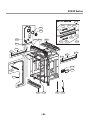
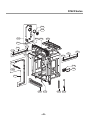
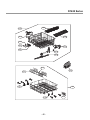
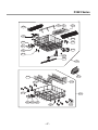
1
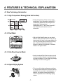
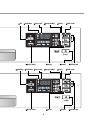
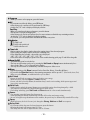
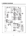
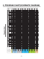
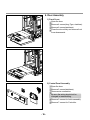
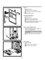
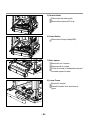
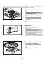
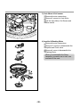
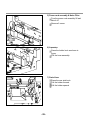
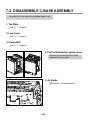
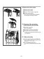
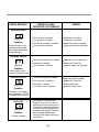
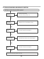
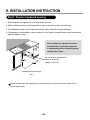
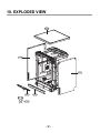
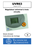
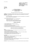
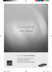
DISHWASHER
SERVICE MANUAL
NOTE
BEFORE SERVICING THE UNIT, PLEASE READ THIS MANUAL CAREFULLY
FOR SAFETY AND CORRECT SERVICES.
MODEL : D1420W(L,M,T,B,C,D,A)F
D1421W(L,M,T,B,C,D,A)F
D1422W(L,M,T,B,C,D,A)F
D1423W(L,M,T,B,C,D,A)F
D14131WF / D14135LF
D14138AC / D14121WH
LD-4321W / LD-4421M
LD-4421PV / LD-4421NV
Un guide d'utilisation vidéo est disponible sur
www.guidelg.com/lave-vaisselle
You may also find user manual in video version at following link
www.guidelg.com/dishwasher
CONTENTS
1. CAUTION......................................................................................................................... 4
2. SPECIFICATIONS ........................................................................................................... 5
3. PARTS NAME .................................................................................................................. 6
4. FEATURES & TECHNICAL EXPLANATION ................................................................... 7
5. WIRING DIAGRAM...................................................................................................... 12
6. PROGRAM CHART (SCHEMATIC DIAGRAM) ............................................................ 13
7. HOW TO DISASSEMBLE ............................................................................................ 14
8. TROUBLE SHOOTING METHODS .............................................................................. 27
A. TROUBLE SHOOTING ACCORDING TO DISPLAYED ERROR MESSAGE.......... 27
B. TROUBLE DIAGNOSES AND REPAIR BY SYMPTOM........................................... 29
9. INSTALLATION INSTRUCTION ................................................................................... 33
10. EXPLODED VIEW .......................................................................................................37
-3-
CAUTION !
DISCONNECT POWER CORD BEFORE SERVICING
RECONNECT ALL GROUNDING DEVICES
IMPORTANT SAFETY NOTICE !
This service information is intended for individuals
possessing adequate backgrounds of electrical,
electronic and mechanical experience.
Any attempt to repair this appliance may result in
personal injury and property damage.
The manufacturer or seller can not be responsible
for the interpretation of this information, nor can it
assume any liability in connection with its use.
-4-
2. SPECIFICATION
SPECIFICATION
ITEM
Rated Voltage / Frequency
AC 220V/50Hz
Installation
AC 230V/50Hz
AC 240V/50Hz
Freestanding
Place Settings
14
Product Dimension(mm)
600(W)
Product Weight(Kg)
600(D)
850(H)
60kg
Color
White / Luxury Silver / Titanium / STS
Black / ACM / Dark Red / Perl Silver
Tub Material
Stainless Steel
Control
Electronic
Rated Power(Watt)
1,534
1,670
1,812
Heater Power(Watt)
1,464
1,600
1,742
Programs
6
Rack
Nylon Coating
Upper Rack
Adjustable type
Lower Rack
D1420 / D1421 / D1423 : 50% Fold down, Removal type
D1422 : 50% Fold down
Water Consumption
14 (Eco)
Power Consumption (kWh)
1.08 (Eco)
Operating Time (min)
199
Fan Dry System
Yes
Delay Start Function
Yes
Auto-Off Power Switch
Yes
Process Monitor
Yes
Wash Level
5
Operating Water Pressure (Bar)
0.5 ~ 8
-5-
3. PARTS NAME
1. Control Panel
2. Door Handle
3. Front Cover
4. Lower Cover
5. Display Window
6. Power Button
7. Drain Hose
8. Inlet Hose
9. Power Cord
10. Adjustable Leg
11. Upper Rack
12. Cutlery Rack
13. Detergent And Rinse Aid Dispenser
14. Vapor Vent Cover
15. Upper Spray Arm
16. Lower Spray Arm
17. Filter ASM
18. Lower Rack
19. Salt Container Cap
20. Cutlery Rack
Funnel
The appearance and specifications may vary without notice.
-6-
4. FEATURES & TECHNICAL EXPLANATION
4-1 New Technology Introduction
4-1-1. High Temperature Rinsing (Extra Hot function)
• During the high temp. Rinse course, water
temperature in an dishwasher reaches 80°C,
considerably higher than the average rinse
temperature in conventional
dishwashers(65°C). This is how Rinse 80°C
can eliminate some bacteria such as
salmonella.
4-1-2. Dual Wash
• With the Dual Wash System you can select
different water pressure levels not only for the
lower basket, but also for the upper basket. So
you can get strong water pressure for the big
pots in the lower basket and soft water
pressure to protect your delicate or valuable
dishes in the upper basket.
4-1-3. Slim Direct Inverter Motor
• Newly introduced Slim Direct Inverter motor is
inverter-controlled. Speed is controlled based
on program selection. It also offers high energy
efficiency to minimize energy loss.
4-1-4. Hybrid Drying System
• This is one of the best performance solutions
for drying dishes because it minimizes venting
humid air to the outside of the dishwasher. In
addition, this system ensures better drying
results compared to the condensing drying
system.
Dry
Air
Moist
Air
Mixed
Air
-7-
4-2 Display Panel
� MODEL : D1420 / D1423 Series
①Program
� MODEL : D1421 / D1422 Series
①Program
-8-
②UV
③Indicator
④Time Left
⑤Beep On/Off
⑪Delay Start
⑩Spray
②Cool Dry ③Indicator ④Time Left
⑤Beep On/Off
⑪Delay Start
⑩Spray
-9-
⑥Rinse
⑦Half Load
⑨Power
⑥Rinse
⑧Child Lock
⑦Half Load
⑨Power
⑧Child Lock
① Program
• When you want to select program, press this button.
② UV
• If you want to sterilize the dishes, press UV button.
• After drying cycle, sterilizer will be performed by UV lamp.
• At this time, “St” code is displayed in display window.
Cool Dry
• When you want better drying performance, press this button.
• This process is not part of the program.
• After drying cycle, the fan will operate for a few more minutes to diminish any remaining moisture.
At this time, “Cd” code is displayed in display window.
• If you want, you can open the door and unload the dishes at any time.
③ Indicator
• Child Lock.
• Refill with special salt.
• Refill with rinse aid.
④ Time Left
• Before starting, the display window shows the running time of the selected program.
• After starting, the display window shows the remaining time.
• If the dishwasher has a trouble, the trouble type is displayed.
“OE”, “FE”, “IE”, “EI”, “HE”, “CE”, “LE”, “tE”
• If this error letters are displayed, please refer to the trouble shooting guide page 25 and follow the guide.
⑤ Beep On/Off
• The dishwasher must be switched on.
• The beep on/off function can be set by pressing the Half Load and Spray button simultaneously for a
few seconds. Then, a “On” will appear in the display.
• The beep on/off function is automatically canceled when power failure occur.
⑥ Rinse
• Repeated pressing of the Rinse button will select Extra Hot, Rinse+, Extra Hot & Rinse+.
• If you select the Extra Hot function, the operating temperature will be up to 80℃. (Dual wash, Auto, Eco)
• When you select Rinse +, an additional rinse cycle is added.
⑦ Half Load
• In case of small load, use upper or lower rack only to save energy.
• With each press, can select Upper or Lower rack only.
• In case you don’t select this button, the machine always works vario washing, which operate upper and
lower spray arm alternately.
⑧ Child Lock
• Used to lock or unlock the control buttons to prevent all the setting from being changed by a child.
• This function is automatically canceled when power failure occur.
• For locking/ unlocking, press Half Load and Rinse button for a few seconds simultaneously.
⑨ Power
• For operating, press this button first for power on.
• After operating, this button automatically switches off for safety and energy saving.
• In case of irregular surge disturbance to the machine, the power may be automatically turned off for safety.
⑩ Spray
• With each press, the level of water jet is changed to Strong, Medium and Soft in a sequence.
⑪ Delay Start
• If you want to delay the start of selected program, press this button.
• Pressing this button will increase time by 1 hour.
• The delay start time can be adjusted from 1 hour to 19 hours.
- 10 -
4-3 TEST MODE
CHECK PROGRAM(START IN THE STATE OF THE CLOSED DOOR)
Checking points
The number of
pushing button
DISPLAY
Half Load + Rinse
+ POWER Button
1 TIME
1n0H : 1U00
All LEDs are lighting
Program Button
1 TIME
11 : 11
Dual Wash
Cool Dry or UV Button
1 TIME
12 : 22
Cool Dry or UV
Delay Start Button
1 TIME
13 : 33
Delay Start
Half Load Button
1 TIME
14 : 44
Half Load
Rinse Button
1 TIME
15 : 55
Rinse
1 TIME
Sensing value
Turbidity Sensor
Auto, Eco, Gentle, Quick
Pre Wash, Dual Wash
2 TIME
n02
Washing Motor
UV
3 TIME
n03
Drain Pump
Delay Start
4 TIME
Frequency
Inlet Valve
Child Lock, Salf Refill, Rinse Refill
5 TIME
n05
Dispenser
Wash
6 TIME
n06
Heater(for 10 sec.)
Rinse
7 TIME
Temperature
Fan Motor
Dry
8 TIME
n08
Regeneration Valve
Upper
9 TIME
n09
UV Lamp (UV lamp use only)
Lower
10 TIME
n0A
Vario motor Vario S/W OFF
Extra Hot, Rinse+
11 TIME
n : 0b
Vario motor Vario S/W ON
Strong, Medium, Soft
BUTTON
Spray Button
12 TIME
Load
n : 0C
AUTO OFF S/W
LED
Operate C1 mode(for 1min.)
Drain(for 42sec.) Supply
water Push Spray Button
(Auto Off)
Micro S/W must be ON to operate HEATER
※ CHECK
MODE
BUTTON
OPERATION
Delay Start + Power
Buzz On/Off
Program Button + Half Load
Display Inner Temperature
Program Button + Delay Start
Display Water Supply Frequency
Program Button + Spray
Display Soil Index
① Cool Dry or UV + Power
② Cool Dry or UV
③ Spray
*Select Hardness Level setting mode (Default :H4)
*Change hardness level (H4 H5 H6 H7 H0 H1 H2 H3 H4)
*Set Hardness Level
- 11 -
5. WIRING DIAGRAM
- 12 -
- 13 -
Pre-Wash
Quick
Gentle
Economy
Auto(Ⅲ)
Auto(Ⅰ)
Dual_wash
Program
Medium
(Half Load)
Medium
(default)
Soft
(Half Load)
Soft
(default)
Medium
(Half Load)
Medium
(default)
Strong
(Half Load)
Strong
(default)
Soft
(Half Load)
Soft
(default)
Medium
(Half Load)
Medium
(default)
Strong
(Half Load)
Strong
(default)
Soft
(Half Load)
Soft
(default)
Strong
(Half Load)
Strong
(default)
Soft
(Half Load)
Soft
(default)
Strong
(Half Load)
Strong
(default)
Medium
(default)
spray
level
Sec.
Min.
Hz & Temp.
Sec.
Min.
Hz & Temp.
Sec.
Min.
Hz & Temp.
Sec.
Min.
Hz & Temp.
Sec.
Min.
Hz & Temp.
Sec.
Min.
Hz & Temp.
Sec.
Min.
Hz & Temp.
Sec.
Min.
Hz & Temp.
Sec.
Min.
Hz & Temp.
Sec.
Min.
Hz & Temp.
Sec.
Min.
Hz & Temp.
Sec.
Min.
Hz & Temp.
Sec.
Min.
Hz & Temp.
Sec.
Min.
Hz & Temp.
Sec.
Min.
Hz & Temp.
Sec.
Min.
Hz & Temp.
Sec.
Min.
Hz & Temp.
Sec.
Min.
Hz & Temp.
Sec.
Min.
Hz & Temp.
Sec.
Min.
Hz & Temp.
Sec.
Min.
Hz & Temp.
Sec.
Min.
Hz & Temp.
Sec.
Min.
Hz & Temp.
Category
Drain
Stop
43
560
Water supply
30 10
30 10
30 10
43
560
43
560
560
43
560
30 10 43
560
30 10 43
560
30 10 43
560
30 10 43
560
30 10 43
560
30 10 43
560
30 10 43
560
30 10 43
560
30 10 43
560
30 10 43
560
30 10 43
560
30 10 43
560
30 10 43
560
30 10 43
560
30 10 43
540
30 10 43
540
30 10 43
540
30 10 43
540
30 10 43
30 10
Stop
1
1
1
1
1
1
1
1
1
1
1
1
1
1
1
1
1
1
1
1
1
1
1
Wash
8
12
2
2
2
2
2
2
2
2
2
2
2
2
2
2
2
Stop
1
1
1
1
1
1
1
1
1
1
1
1
1
1
1
Drain S
Drain
3
3
3
3
3
3
3
3
3
3
2
2
2
2
3
Stop
5
40
Water supply
40
10 5
40
10 5
40
10 5
40
10 5
40
10 5
40
10 5
40
10 5
40
10 5
40
10 5
40
10 5
75
10 5
75
10 5
75
10 5
75
10 5
10
Wash
7
7
7
7
7
7
7
7
7
7
7
7
7
7
7
Drain
Stop
Stop
15
70 3 30
70 3 30
70 3 30
70 3 30
40
15
40
15
40
15
40
15
165
70 15 30 15
165
70 15 30 15
230
70 15 30 15
230
70 15 30 15
70 13 30
Water supply
170
Drain T
Wash
5
12
5
12
5
8
5
8
12
40
DrainP
Drain
Stop
Drain
Stop
Stop
7
225
Water supply
120
20 6 20 8 20 7
150
20 6 20 8 20 7
150
20 6 20 8 20 7
150
20 6 20 8 20 7
150
20 6 20 8 20 7
150
20 6 20 8 5 7
60
20 5 20 2 20 7
60
20 5 20 2 20 7
60
20 5 20 2 20 7
60
20 5 20 2 20 7
225
20 10 20 10 20 7
225
20 10 20 10 20 7
240
20 10 20 15 20 7
240
20 10 20 15 20 7
20 10 20 10 20
Stop
1
1
1
1
1
1
1
1
1
1
1
1
1
1
1
Wash
8
50
50
8
10
50
12
50
10
50
15
50
12
45
16
45
16
45
20
45
20
45
24
45
28
43
28
43
58
66
29
66
39
20
50
40
50
32
55
52
55
52
60
10
10
10
10
10
10
10
10
10
10
10
10
10
10
10
10
10
10
10
10
10
Wash
Drain
Drain
8
8
8
8
8
8
8
8
8
8
8
8
8
8
8
8
8
8
8
8
8
Drain C
Stop
Drain
Stop
Stop
43
500
Water supply
30 20 30 33 5
500
43
500
30 20 30 33 5 43
500
30 20 30 33 5 43
500
30 20 30 33 5 43
500
30 20 30 33 5 43
500
30 20 30 33 5 480
500
30 20 30 33 5 43
500
30 20 30 33 5 43
500
30 20 30 33 5 43
500
30 20 30 33 5 43
500
30 20 30 33 5 43
500
30 20 30 33 5 43
500
30 20 30 33 5 43
470
30 20 30 33 5 43
490
30 20 30 33 5 43
470
30 20 30 33 5 43
495
30 20 30 33 5 43
495
30 20 30 33 5 43
515
30 20 30 33 5 43
515
30 20 30 33 5 43
30 20 30 33 5
Stop
1
1
1
1
1
1
1
1
1
1
1
1
1
1
1
1
1
1
1
1
1
Wash
4
45
8
45
4
45
8
45
4
45
8
45
7
12
7
12
7
12
7
28
7
28
12
40
12
40
12
10
Wash
Drain
Drain
8
Stop
30
Drain C
Drain
Stop
20 30 33 5
Stop
Drain A
Drain
Rinse2
Drain
Rinse
Water supply
43
500
Stop
1
Wash
8
10
10
10
10
10
10
10
10
10
10
10
10
10
10
10
10
10
10
10
10
10
Wash
Drain
Drain
8
8
8
8
8
8
8
8
8
8
8
8
8
8
8
8
8
8
8
8
8
Drain C
Stop
30 20 30
30 20 30
30 20 30
30 20 30
30 20 30
30 20 30
30 20 30
30 20 30
30 20 30
30 20 30
30 20 30
30 20 30
30 20 30
30 20 30
30 20 30
30 20 30
30 20 30
30 20 30
30 20 30
30 20 30
43
Stop
1
29
70
Heating A
29
510
70
33 5 43 1
29
510
70
33 5 43 1
29
485
70
33 5 43 1
29
485
70
33 5 43 1
39
470
59
33 5 43 1
21
490
65
33 5 43 1
40
450
72
33 5 43 1
21
500
65
33 5 43 1
29
500
70
33 5 43 1
29
500
70
33 5 43 1
29
500
70
33 5 43 1
29
500
70
33 5 43 1
29
500
70
33 5 43 1
29
500
70
33 5 43 1
20
500
65
33 5 43 1
20
500
65
33 5 43 1
16
500
65
33 5 43 1
16
500
65
33 5 43 1
16
500
65
33 5 43 1
16
500
65
33 5 43 1
30 20 30 33 5
500
Heating Rinse
Heating Rinse
Stop
Rinse1
Drain
Main Wash
Stop
Main Wash
Drain
Prewash3
Water supply
Prewash
Heating B
1
1
1
1
1
1
2
2
2
2
2
2
2
1
2
2
1
1
1
1
2
Stop
1
1
1
1
1
1
1
1
1
1
1
1
1
1
1
1
1
1
1
1
1
1
1
Drain
45
45
45
45
45
45
45
45
45
45
45
45
45
45
45
45
45
45
45
45
45
45
45
Dry
Dry
DrainB
10
10
10
10
10
10
10
10
10
10
10
10
10
10
10
10
10
10
10
10
10
10
10
Stop
Prewash2
20
20
20
20
20
20
20
20
20
20
20
20
20
20
20
20
20
20
20
20
20
20
20
Drain
Prewash1
Stop
30
30
30
30
30
30
30
30
30
30
30
30
30
30
30
30
30
30
30
30
30
30
30
Dry
30
30
30
30
30
30
30
30
30
30
30
30
30
30
30
11
15
38
42
40
46
44
61
100
109
104
113
108
117
115
199
116
199
111
162
123
174
170
Time(Min.)
Working
Time
6. PROGRAM CHART(SCHEMATIC DIAGRAM)
7. HOW TO DISASSEMBLE
BEFORE DISASSEMBLING THE DISHWASHER ;
1) Remove the plug from electric outlet to avoid electric shock.
2) Close the Water Tap(faucet).
3) Remove all dishes and items in the dishwasher.
4) Remove the Lower Rack and the Upper Rack.
5) In case of the water softner assembly model, open the water softner cap to flow out the
water to sump and drain to avoid the floor wet.
6) If necessary, remove the inlet hose and drain hose to avoid the hose damages.
7) Prepare some towels to avoid floor wet by the water left in the dishwasher.
7-1. FULL DISASSEMBLE
1. Top Table
1) Remove the rear 2 screws.
2) Pull and lift the top table.
2. Low Cover
3. Side Cabinet-R/L and Tub Felt
1) Cabinet-R
Remove front 4 screws.
Remove rear 3 screws.
2) Cabinet-L
Remove front 4 screws.
Remove rear 3 screws.
2) Tub Felt
Pull the Tub Felt.
- 14 -
4. Door Assembly
1) Front Cover
Open the door.
Remove 4 screws(long Type, stainless).
Remove 6 screws(stainless).
Close the door slowly and remove front
cover downwards.
2) Control Panel Assembly
Open the door.
Remove 2 screws(stainless).
Remove wire connection.
Be sure the wiring should not be
changed in reassembling.
Remove 3 screws for Latch assembly
Remove 7 screws for Controller.
- 15 -
3) Fan
Open the door.
Remove the wire connections.
Turn the Inner Cover counterclockwise.
Remove the air duct.
4) Detergent Dispenser
Close the door.
Remove the wire connections.
Remove 6 screws with brackets.
Push the Detergent slowly pulling up the
Flange by Standard Screwdriver.
5) Door Spring (Right & Left)
Push the Spring upwards and take it off
from the Hinge Bracket.
Be careful not to be injured by the sharp
edge of Tub.
Take off the Hinge Link from the Hinge.
6) Door Liner
Open the door.
Remove the wire connections.
Pull the Door liner upwards.
- 16 -
5. Tub assembly
1) Rack
Remove the Upper rack and Lower rack.
2) Air guide Nut and Water softner Cap&Nut
Turn the Air guide Nut counterclockwise.
(Special tool might be needed.)
Be careful the rubber packing of air guide
assembly should not be lost.
Turn the Water softner Cap
counterclockwise.
3) Nozzle
Pull up the nozzle.
4) Filter Assembly
Turn inner filter counterclockwise and lift
inner filter and middle filter.
You can disassemble inner filter and
middle filter by pulling opposite direction.
Lift up main filter.
Lift up micro filter.
- 17 -
5) Nozzle Holder
Disconnect the water guide
Remove 4screws and lift it up
6) Sump Holder
Remove the Sump Holder(5EA).
7) Base spacer
Remove front 2 screws.
Remove side 2 screws.
Lift the front side of dishwasher and pull
the base spacer forward.
8) Lower Frame
Remove 2 screws.
Press the holder hook as shown in
figure.
- 18 -
9) Tub sub Assembly
Remove side 4 screws.
Remove 3 Earth screw of right side.
Remove rear 4 screws.
Lift tub assembly upward.
(Be sure water softner is not blocked.)
Be careful not to be injured or scratch
floor by the sharp edge of tub.
6. Tub sub Assembly
1) Top Frame
Remove front 2 screws.
Remove side 2 screws.
Lift up top frame.
2) Balance Weight
Remove real 4 screws.
Lift up balance weight.
- 19 -
3) UV Lamp(Limited on some models.)
Remove the wire connections.
Remove side 4 screws.
Push the UV Lamp slowly.
4) Door Bracket
Remove 4 screws.
Lift up ward.
7. Air Guide Assembly
Lift it upward to disconnect from Water
Softner.
Disconnect the wiring connection.
Remove 3 hoses assembly.
Be careful the o-ring should not be lost.
Be careful not to wet the floor by the
water left in the hose.
- 20 -
8. C-Base Assembly
Remove the wire connections.
Lift them upward.
Be careful not to wet the floor by the
water left in the sump
Pull out the float switch with pressing
downward softly.(not on all models)
Detach the washing motor and heater
assembly by pulling opposite direction
to sump.
Remove the 3 screw for drain motor.
1) Water softner
Remove the hose assembly.
Lift it upward.
Be careful not to wet the floor by the
water left in the water softner.
You can disassemble the solenoid valve
by unscrew the 2 screw.
Be sure not to lost the spring and bobbin.
2) Heater & Drain pump
Remove the wire connections.
Pull the Heater out of the Sump after
releasing the nut.
Remove 3 screw to disassemble the
Drain pump.
- 21 -
3) Vario Motor & Soil sensor
Remove the wire connections.
Remove 2 screws for Vario Motor.
Pull the Vario Motor, Soil Sensor and
Micro switch.
4) Impeller & Washing Motor
Remove the wire connections.
Remove 10 screws to disassemble the
Impeller and Check valve.
Remove 4 screw to disassemble the
Washing Motor.
When you reassemble the Sump
Assembly, be careful not to kink, tear
and take off the seal.
- 22 -
5) Power cord assembly & Noise Filter
Turn the power cord assembly 90 and
take it off.
Remove 2 screw.
6) Aquastop
Press the holder hook as shown in
figure.
Pull the hose assembly.
7) Drain Hose
Press the rear side hook.
Pull the holder forward.
Pull the holder upward.
- 23 -
7-2. DISASSEMBLE C-BASE ASSEMBLY
Be careful not to be injured by the sharp edge of tub.
1. Top Plate
See 7-1. 1. (Page 16)
2. Low Cover
See 7-1. 2. (Page 16)
3. Cabinet-R/L
See 7-1. 3. (Page 16)
4. Put the Dishwasher upside down.
Be careful not to wet the floor by the
water left in the air guide.
5. Air Guide
Disconnect 1 hoses assembly.
- 24 -
6. Disconnect the wire
Remove the wire from the wire hook at the
base.
Remove 3 Earth screws of right side.
Remove the Float switch.
7. Base spacer
Remove front 2 screws.
Remove side 2 screws.
Lift the front side of dishwasher and pull
the base spacer forward.
8. Lower Frame
Remove 2 screws.
Press the holder hook as shown in
figure.
- 25 -
9. Remove the side screws
Remove side 4 screws.
Remove rear 4 screws.
Remove 3 Earth screws of right side.
Lift base upward slightly
(You can’t lift up base perfectly because
of some parts connecting to base.)
10. Disconnect the connecting
points between tub and base
Disconnect noise filter.
(Not on all models)
Disconnect of power cord assembly.
Disconnect wire from the Aquastop.
Now, you can remove the base from the
tub perfectly.
11. C-Base Assembly
You can repair the parts in the C-Base like
heater, washing motor, drain motor etc. you
may refer to 7-1. 8. 1)~10)
Don’t disassemble sump by 7-2.
If you want to disassemble the sump, follow
7-1.
- 26 -
8.TROUBLE SHOOTING METHODS
A. TROUBLE SHOOTING ACCORDING TO DISPLAYED ERROR MESSAGE
ERROR MESSAGE
POSSIBLE CAUSE
FOR ERROR OCCURRENCE
INLET ERROR
The Water Tap is not opened.
The Inlet Hose is kinked.
The Filter of inlet valve clogged
by impure water.
displayed
Condition
Not reached to the normal water level in spite
of 10 min. water supply
DRAIN ERROR
The Inlet Water Valve is normal ?
The water pressure is very low.
( below 0.5 kgf/ )
Inlet valve is blocked by safety
device for leakage sensing.(In
case of Inlet Valve)
REMEDY
Open the Water Tap.
Repair the Inlet Hose.
a) Close the Water Tap.
b) Unscrew the Inlet Hose (Inlet Valve side)
c) Clean the Filter of Inlet Valve.
Replace or repair the Inlet Valve.
Check the water remain on the base.
1) Check the point of damages and
repair or replace the related parts.
2) Disconnect the inlet hose to
dishwasher to unlock the safety valve.
The Filter clogged.
Clean the Filter.
The Drain Hose kinked or blocked.
Remove the cause of kink or block.
The Drain Pump/Motor or circuit is
Replace the Drain Pump/Motor or
troubled.
repair the Circuit.
Water leakage in Hose connections.
Replace the connections of Hose.
Water is leaked by damages.
Check the point of damages and
Impeller of the washing Pump is
repair or replace the related parts.
Replace the washing pump.
displayed
Condition
Not fully drained out in
spite of 5 min. drain
operation
LEAKAGE ERROR
displayed
Condition
worn away.
The Thermal Protector of the
washing motor is functioned.
The water level in Tub
goes down during
operation
- 27 -
Check the applied voltage.
ERROR MESSAGE
POSSIBLE CAUSE
FOR ERROR OCCURRENCE
REMEDY
EXCESS ERROR
The Inlet Valve is troubled.
Replace the Inlet Valve.
displayed
The Air Break is troubled.
Replace the air breaker.
Condition
The Sensor Assembly is troubled.
Replace the sensor assembly.
The Controller is troubled.
Repair or replace the Controller.
The Circuit of thermistor is troubled.
Repair the Circuit of thermistor.
Thermistor is troubled.
Replace the Thermistor.
The Controller is troubled.
Repair or replace the Controller.
The Circuit of Heater is troubled.
Repair the Circuit of Heater.
The Thermistor is troubled.
Replace the Thermistor.
The Heater is shorted.
Replace the Heater.
The Relay Circuit is troubled.
Repair the Relay Circuit..
Excessive water is supplied than normal water
level.(Automatically drain
Pump operated.)
THERMAL ERROR
displayed
Condition
The resistance of thermistor not normally out put.
HEATER ERROR
displayed
Condition
The water is not heated or
the temperature in the Tub
is overheated to over 95¡C
COOL DRY
displayed
Condition
No error message
This process is not part of the
program. At this time, the fan will
operate for a few more minutes to
diminish any remaining moisture. If
you want, you can now open and
unload the dishwasher. Otherwise
the dishwasher automatically
switches off for safety and energy
saving later.
- 28 -
B. TROUBLE DIAGNOSES AND REPAIR BY SYMPTOM
No Power on when the power button pressed.
The plug is correctly
inserted in the
Socket-Outlet?
NO
• Insert the Plug Correctly.
• Check the electricity is failed or not.
YES
The Fuse or
Circuit Breaker
of house is O.K?
NO
• Replace the Fuse or Circuit Breaker of house.
YES
The Thermal Fuse
is O.K?
NO
• Check the Thermal Fuse and replace it.
YES
The Power Switch or
the Circuit is O.K?
NO
• Check the Power Switch or the circuit and repair it.
YES
The C-Trans Circuit
is O.K?
NO
• Check the C-Trans Circuit. and repair it.
YES
C h e c k t h e C o n t r o l l e r. ( P o w e r C i r c u i t )
- 29 -
The Wash Pump/Motor does not run.
The Door is tightly
closed?
NO
• Close the Door Tightly.
• Check the Door Switch in Latch Handle.
YES
The Pump/Motor is
not blocked?
NO
• Remove the cause of block or replace the Pump/Motor.
NO
• Repair the circuit.
YES
The circuit of Pump/
Motor is O.K?
YES
The Thermal Protector of Motor is
tripped?
YES
• Cool the Motor Until the Thermal Protector reset.
NO
Replace the Pump/Motor
- 30 -
Washing Results are not Satisfactory
After washing, are there still
White deposits or streaks on
the dishes?
YES
Reduce the amount of Rinse-Aid
(for Streak)
Does salt refill lamp blink?
(Refill salt)
NO
After washing, are there still
food soils on the dishes?
YES
Check that : - the amount of detergent Correctly used or not
- Filters clogged or not.
- the holes of spray arms blocked or not.
- Utensils are correctly arranged or not.
- Utensils are overloaded or not.
- the spray arm rotating is obstructed or not.
- the program is correctly selected or not.
Dry Results are not satisfactory
Increase the amount of Rinse-Aid.(Set the number higher)
Select the Program that the Rinse temperature is higher.
- 31 -
Power Button not automatically off after operation.
Check the button is blocked by foreign materials.
Check the Power Switch.(Replace it, if necessary.)
Check the Controller.(Replace it, if necessary.)
- 32 -
9. INSTALLATION INSTRUCTION
Step1: Prepare Cupboard opening
1. This dishwasher is designed to fit to the size shown as below.
2. Select a location as close to sink as possible for easy connections to water and drain lines.
3. The dishwasher should not be installed more than 3 meters from sink for proper drainage.
4. If dishwasher is to be installed in corner, minimum 5 cm of space is required between the washer and an
adjacent cabinet or a wall.
If bare chipboard is adjacent to or above
the dishwasher, it should be sealed with
a waterproofing paint or sealant to prevent
swelling due to steam.
Cut out for hoses and electrical
cables on either side.
( approx.. 100 X 75 )
Cupboard Opening Dimension
( mm )
Ensure the floor under the dishwasher is at the same level as the rest of the room to allow for any
service requirements.
- 33 -
Step 2 : PREPARE ELECTRICAL WIRING
CAUTION
For personal safety, remove house fuse or open circuit breaker before installation.
Do not use an extension cord or adapter plug with this appliance.
Electrical and grounding connections must comply with the national electrical code/provincial and
municipal code and/or other local codes.
1. This appliance must be supplied with correct rating voltage and hertz as shown on instruction manual,
and connected to an individual, properly grounded branch circuit, protected by minimum 15 amp circuit
breaker or time delay fuse.
Wiring must be 2 wires with ground.
2. The power point must be in a accessible location adjacent to and not behind the dishwasher and within
1.2 meters of the dishwasher side. A correctly rated, wired and earthed extension cord may be used if
necessary.
(See Fig. A)
3. The power point must be correctly earthed, if in doubt, have it checked by a qualified Electrician.
No other appliance shall be connected to the same plug outlet by a double adapter or similar plug.
Step 3 : PREPARE DISHWASHER FOR INSTALLATION
1. Lay the dishwasher on its back.
2. Adjust the legs to the needed height
of cabinet as shown at below.
Free Standing
Built-in
Step 4 : INSTALL THE DISHWASHER IN CUPBOARD
1. Before sliding the dishwasher into the cupboard opening,
all necessary final height adjustment and
balancing adjustment should be done using the spanner.
2. Slide the dishwasher into the cabinet opening carefully.
Make sure that the drain hose inside the cabinet should
not be kinked or exceeded.
CAUTION
If the height of cupboard is below 850mm,
you should remove the top table by
unscrewing the 2 screws. (Two of front
and two of rear)
- 34 -
Step 5 : DRAIN LINE CONNECTION
1. If the end drain hose does not fit to the drain line, use a piece of rubber connector (not supplied)
that must be resistant to heat and detergent and may be obtained from a plumbing shop.
2. There are 2 typical connections as shown in Figure A, B
¥ The recommended methods of drain hose connection must be adhered to within the areas of Water Board
Authority. Several other options are commonly used outside this area and local council or plumbers should
be able to advise of these.
¥ The S trap spigot must be drilled out cleanly and free of obstruction to its maximum internal diameter, if
used for drainage.
¥ To prevent syphoning, one of the following instruction methods must be followed :
When the drainage hose is connected to a sink S trap or waste disposal unit, the hose must be looped up
to the under side of the bench top and secured.
Fig. A
When the drain hose is connected to a separate stand pipe, it is essential that an air tight connection is
made. Refer to Fig. B
Fig. B . Drainage connection-stand pipe
- 35 -
Drain Hose Extension
Drain Hose extension kits are available from through your local service centre.
Extend drain Hose as shown below.
200 mm Max.
Copper pipe
fl 20mm flared
at drain nose
and other end
if required.
770 mm Min. / 1000 mm Max.
300 mm Min.
Sink
Use the couplings for connections when you
extend drain hose.
Drain hose extension or 16-20mm inside fl rubber
hose able to withstand 90ßC hot water
Step 6 : WATER SUPPLY CONNECTION
1. Connect the water supply hose to the valve behind dishwasher
and the water tap as shown in figure.
This dishwasher may be fed with either hot or cold water. If the
water can not be maintained below 65°C, the dishwasher must
be connected to cold water.
2. When connecting, the sealing tape or sealing compound should
be used to avoid water leaks.
Make sure that the line is not kinked or sharply bent.
Water tap
Water supply
hose
Step 7 : FINAL CHECK AND ASSEMBLING
1. Securely hand tighten supply hose to water supply.
Plug power cord into an earthed power point and switch on.
2. Operate the dishwasher through one cycle (Quick cycle is recommended) to check for water leak
and operating conditions.
- 36 -
10. EXPLODED VIEW
A001
A020
A010
A050
A040
E006
- 37 -
D1420 Series
F110
F113
F111
F117
F060
F112
F050
F117
F111
F040
E001 F008
A002
F118
F210
F113
F022
F117
F105
F112
F171
F117
F215
E010
F118
F192
F220
F230
F004
F191
F001
F132
- 38 -
F011
F013
D1421 Series
F110
F113
F111
F117
F060
F112
F050
F117
F111
F040
A002
E001 F008
F118
F113
F210
F022
F117
F105
F112
F171
E010
F117
F215
F118
F192
F004
F191
F001
F132
- 39 -
F011
F013
D1422 Series
F060
F050
F040
A002
E001 F008
F022
F117
F105
F112
F171
E010
F117
F215
F118
F192
F004
F191
F001
F132
- 40 -
F011
F013
D1423 Series
F060
F050
F040
A002
E001 F008
F022
F117
F105
F112
F171
F117
F215
E010
F118
F192
F220
F230
F004
F191
F001
F132
- 41 -
F011
F013
K200
K212
K204
K006
K262 K216
K252
K260
K251
K203
K010
K124
K110
K209
K201
K121
K101
K122
K001
F142
K002
F141
F174
- 42 -
F035
F037
F034
F032
A130
A131
F031
F036
A160
M230
M008
F001
A030
M270
- 43 -
M023
M260
M090
A276
M072
M073
M071
M070
M074
M001
A120
M120
M025
M130
M035
M006
M121
M088
M031
M005
M029
M028
M010
M027
M026
M087
M140
M081
M060
M051
- 44 -
D1420 / D1421 Series
A170
A171
A172
A174
A175
A173
A154
A147
A159
A150
A156
A080
A102
A146
A101
A155
A103
A145
A070
A060
A110
A144
A149
A147
A157
A140
A101 A102 A103
A146
- 45 -
A142
D1422 Series
A090
A150
A080
A156
A102
A101
A155
A103
A070
A060
A147
A110
A144
A157
A140
A146
- 46 -
A142
D1423 Series
A154
A090
A147
A159
A156
A080
A102
A146
A101
A155
A103
A145
A070
A060
A150
A110
A144
A149
A147
A157
A140
A101 A102 A103
A146
- 47 -
A142
P/No. : 3828DD3007T