1
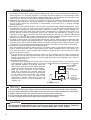
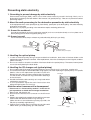
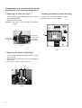
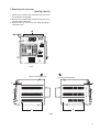
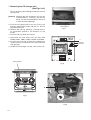
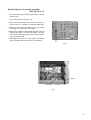
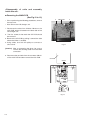
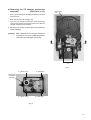
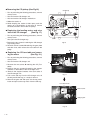
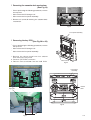
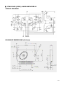
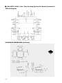
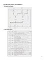
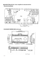
MCD-338 SERVICE MANUAL Contents Safety precautions ---------------------------Preventing static electricity ----------------Important for laser products ---------------Disassembly method -----------------------Adjustment method -------------------------- 1- 2 1- 3 1- 4 1- 5 1- 17 Flow of functional operation until TOC read -------------Maintenance of laser pickup -------------Replacement of laser pickup -------------Description of major ICs ------------------- 1- 19 1- 20 1- 20 1- 21 Safety Precautions 1. This design of this product contains special hardware and many circuits and components specially for safety purposes. For continued protection, no changes should be made to the original design unless authorized in writing by the manufacturer. Replacement parts must be identical to those used in the original circuits. Services should be performed by qualified personnel only. 2. Alterations of the design or circuitry of the product should not be made. Any design alterations of the product should not be made. Any design alterations or additions will void the manufacturer's warranty and will further relieve the manufacture of responsibility for personal injury or property damage resulting therefrom. 3. Many electrical and mechanical parts in the products have special safety-related characteristics. These characteristics are often not evident from visual inspection nor can the protection afforded by them necessarily be obtained by using replacement components rated for higher voltage, wattage, etc. Replacement parts which have these special safety characteristics are identified in the Parts List of Service Manual. Electrical components having such features are identified by shading on the schematics and by ( ! ) on the Parts List in the Service Manual. The use of a substitute replacement which does not have the same safety characteristics as the recommended replacement parts shown in the Parts List of Service Manual may create shock, fire, or other hazards. 4. The leads in the products are routed and dressed with ties, clamps, tubings, barriers and the like to be separated from live parts, high temperature parts, moving parts and/or sharp edges for the prevention of electric shock and fire hazard. When service is required, the original lead routing and dress should be observed, and it should be confirmed that they have been returned to normal, after re-assembling. 5. Leakage currnet check (Electrical shock hazard testing) After re-assembling the product, always perform an isolation check on the exposed metal parts of the product (antenna terminals, knobs, metal cabinet, screw heads, headphone jack, control shafts, etc.) to be sure the product is safe to operate without danger of electrical shock. Do not use a line isolation transformer during this check. Plug the AC line cord directly into the AC outlet. Using a "Leakage Current Tester", measure the leakage current from each exposed metal parts of the cabinet, particularly any exposed metal part having a return path to the chassis, to a known good earth ground. Any leakage current must not exceed 0.5mA AC (r.m.s.) Alternate check method Plug the AC line cord directly into the AC outlet. Use an AC voltmeter having, 1,000 ohms per volt or more sensitivity in the following manner. Connect a 1,500 10W resistor paralleled by a 0.15 F ACtype capacitor between an exposed metal part AC VOLTMETER and a known good earth ground. Measure the AC (Having 1000 voltage across the resistor with the AC voltmeter. ohms/volts, Move the resistor connection to each exposed or more sensitivity) metal part, particularly any exposed metal part having a return path to the chassis, and meausre 0.15 F AC TYPE the AC voltage across the resistor. Now, reverse Place this the plug in the AC outlet and repeat each probe on measurement. Voltage measured Any must not each exposed exceed 0.75 V AC(r.m.s.). This corresponds to 0.5 1500 10W metal part. mA AC(r.m.s.). Good earth ground Warning 1. This equipment has been designed and manufactured to meet international safety standards. 2. It is the legal responsibility of the repairer to ensure that these safety standards are maintained. 3. Repairs must be made in accordance with the relevant safety standards. 4. It is essential that safety critical components are replaced by approved parts. 5. If mains voltage selector is provided, check setting for local voltage. ! CAUTION Burrs formed during molding may be left over on some parts of the chassis. Therefore, pay attention to such burrs in the case of preforming repair of this system. 1-2 Preventing static electricity 1. Grounding to prevent damage by static electricity Electrostatic discharge (ESD), which occurs when static electricity stored in the body, fabric, etc. is discharged, can destroy the laser diode in the traverse unit (optical pickup). Take care to prevent this when performing repairs. 2. About the earth processing for the destruction prevention by static electricity In the equipment which uses optical pick-up (laser diode), optical pick-up is destroyed by the static electricity of the work environment. Be careful to use proper grounding in the area where repairs are being performed. 2-1 Ground the workbench Ground the workbench by laying conductive material (such as a conductive sheet) or an iron plate over it before placing the traverse unit (optical pickup) on it. 2-2 Ground yourself Use an anti-static wrist strap to release any static electricity built up in your body. (caption) Anti-static wrist strap Conductive material (conductive sheet) or iron plate 3. Handling the optical pickup 1. In order to maintain quality during transport and before installation, both sides of the laser diode on the replacement optical pickup are shorted. After replacement, return the shorted parts to their original condition. (Refer to the text.) 2. Do not use a tester to check the condition of the laser diode in the optical pickup. The testers internal power source can easily destroy the laser diode. 4. Handling the CD changer unit (optical pickup) 1. Do not subject the CD changer unit (optical pickup) to strong shocks, as it is a sensitive, complex unit. 2. Cut off the shorted part of the flexible cable using nippers, etc. after replacing the optical pickup. For specific details, refer to the replacement procedure in the text. CD changer Remove the anti-static pin when replacing the CD changer unit unit. Be careful not to take too long a time when attaching it to the connector. 3. Handle the flexible cable carefully as it may break when subjected to strong force. 4. It is not possible to adjust the semi-fixed resistor that adjusts the laser power. Do not turn it. Attention when traverse unit is decomposed * Please refer to “Disassembly method” in the text for pick up and how to detach the CD changer mechanism. 1. Remove the CD changer unit. 2. Disconnect the harness from connector on the CD motor board. 3. Solder is put up before the card wire is removed from connector Cn601on the main board as shown in Fig.1 and Fig. 2. (When the wire is removed without putting up solder, the CD pick-up assembly might destroy.) 4. Please remove solder after connecting the card wire with CN601 when you install picking up in the substrate. Fig.1 Soldering Flexible cable Fig.2 1-3 Important for laser products 1. CLASS 1 LASER PRODUCT 2. DANGER : Invisible laser radiation when open and inter lock failed or defeated. Avoid direct exposure to beam. 3. CAUTION : There are no serviceable parts inside the Laser Unit. Do not disassemble the Laser Unit. Replace the complete Laser Unit if it malfunctions. 4. CAUTION : The compact disc player uses invisible laser radiation and is equipped with safety switches which prevent emission of radiation when the drawer is open and the safety interlocks have failed or are defeated. It is dangerous to defeat the safety switches. FUSE CAUTION CAUTION: REPLACE WITH SAME TYPE AND RATING FUSE (S). ATTENTION: REMPLACER PAR UN(LES) FUSIBLE(S) DE MEME TYPE ET DE MEME VALEUR 1-4 5. CAUTION : If safety switches malfunction, the laser is able to function. 6. CAUTION : Use of controls, adjustments or performance of procedures other than those specified herein may result in hazardous radiation exposure. ! CAUTION Please use enough caution not to see the beam directly or touch it in case of an adjustment or operation check. Disassembly method Commence disassembly of the set by removing the main units and then proceed to the components and assemblies inside the units. Replacement of the fuses and the power IC Top cover CD changer unit Front panel assembly Chassis unit CD changer unit Removing the main PCB Removing the CD changer mechanism assembly Removing the CD pickup Replacing the loading motor and belt of the CD changer tray Replacing the CD tray rotor belt of CD changer, and removing the motor Front panel assembly Removing the cassette deck mechanism Removing the earphone jack PCB Removing the control/FL PCB Removing the cassette deck main motor, and replacing the main belts Removing the leaf switches of the cassette deck mechanism Removing the cassette deck heads Chassis unit Removing the 3-pin regulator Removing the power amp and supply PCB and the Power Trans PCB Removing the sub power PCB 1-5 <Disassembly of the main blocks of the set> Replacement of the fuses and the power IC Replacing the fuses (See Fig.1) Replacing the heat sink cover (See Fig.3) Prior to performing the following procedure, remove the left side BOARD. 1. Replace the fuses inside. 1. Remove four screws B from the rear panel. 2. Pull the heat sink cover outward. [Caution] Be sure to use fuses with the specified ratings. Fuse (F951) T3.15AL 250V Fuse (F953) T1.6AL 250V B Fuse (F952) T1.6AL 250V MCD-338 Fig.1 Fig.3 Replacing the power IC (See Fig.2) Prior to performing the following procedure, remove the top cover. 1. Remove the two screws A from the heat sink between the power IC. 2. Remove the solder fixing the power IC. W Fig.2 1-6 A Removing the top cover (See Fig.4 and 5) 1. Remove six screws C that retain the top cover from the panel rear of the body. 2. Remove six screws D that retain the top cover from the two sides of the body. 3. Remove the top cover from the body by lifting it toward the rear. MCD-338 Fig.4 Right Front panel assembly Left Front panel assembly D D D D Fig.5 1-7 Removing the CD changer unit (See Fig.6 to 9) Prior to performing the following procedures, remove the top cover. [Caution] Although the CD mechanism unit can be removed without removing the CD tray panel, it is still recommended to remove it in order to prevent damage. a. From the front panel side of this set, push in the sections marked with arrows and pull out the CD tray toward the front. b. Remove the CD tray panel by pushing both of its extremities upward in the direction of the arrows. c. Push the CD tray deep into the set. CD tray panel Fig.7 1. Disconnect the cord wires from the main PCB CN403, CN201, CN601, CN401, CN402, and CN205. 2. From the rear of the set, remove two screws E, two screws F and four screws G on the front panel left and right side. 3. Handle the CD changer unit rear, take out the unit. E Antenna terminal F MCD-338 CD tray panel Fig.8 G Fig.6 Fig.9 1-8 Removing the front panel assembly (See Fig.10 to 11) Prior to performing the following procedures, remove the top cover. Also remove the CD changer unit. 1. Disconnect the parallel wire and the cord wire from the connectors J1, CN202 on the power AMP PCB. 2. Remove one screws H retaining the front panel assembly onto the bottom of the body. 3. Remove two screws I on the left and right side of the set retaining the panel front from the bottom and then remove then GND lug b that comes from the power amp and supply PCB. 4. Disengage the claws c on both sides of the front panel assembly and then remove the assembly. H Fig.10 Screw I GND lug a GND lug b Claw c Fig.11 1-9 <Disassembly of units and assembly inside this set> Removing the MAIN PCB (See Fig.12 to 13) Prior to performing the following procedures, remove the top cover. Also remove the CD changer unit. J PAIN PCB 1. Disconnect the wires from CN702, CN703 on the main PCB, which is located on the back side of the CD changer unit. 2. The four screws J that retain the CD PCB should be removed. 3. Remove the CD PCB by pulling it toward the side where the CN701 is located. J 4. Using solder, short the CD pickup to connect to short round. Fig.12 [Caution] After re-connecting the wires, be sure to remove the shorting solder from the GND connection. 5. Disconnect the card wire from the connector CN701 on the main PCB and then remove the main PCB. CD PCB CN701 Short round Fig.13 1-10 J Removing the CD changer mechanism assembly (See Fig.14 to 15) Prior to performing the following procedures, remove the top cover. Also remove the CD changer unit. CD changer unit 1. Turn the CD changer mechanism cover base and remove the screws d connecting the unit to the CD changer mechanism assembly. 2. Removing four screws e retaining the CD mechanism holder assembly. [Caution] When replacing the CD changer mechanism assembly, be sure not to mistake the positions of the silver color and copper color spring. d Fig.14 e ( Red color ) e ( Green color ) CD changer mechanism assembly e ( Red color ) e ( Green color ) Fig.15 1-11 Removing the CD pickup (See Fig.16) CD pickup Prior to performing the following procedures, remove the top cover. Also remove the CD changer unit. Also remove the CD changer mechanism. 1. Widen the section f. 2. While keeping the section f wide open, push the section g in the direction of the arrow to remove the shaft, and then remove the CD pickup. g f Replacing the loading motor and rotor belt of the CD changer (See Fig .17) Prior to performing the following procedures, remove the top cover. Also open the CD changer tray. Shaft 1. Remove the two screws L retaining the CD changer tray loading motor. 2. Remove the two screws M retaining the gear plate and take it out, after remove the rotor belt from the pulley. Fig.16 M Replacing the CD turn table and remov- ing the motor (See Fig. 19 ) Prior to performing the following procedures, remove the top cover. Also remove the CD changer unit. 1. Remove the one screws N retaining the CD (Turn table). 2. Remove the two screws O retaining the stopper brackets on both sides of the CD changer unit. 3. Remove the stopper brackets from both sides of the CD changer unit. 4. Pull out the CD tray from the CD changer unit, all the way and lift the tray (u/~ ward) to remove. 5. Remove the gear and after push out the tray motor locker and pull out the tray motor from the CD tray. L Fig.17 Turn table motor , and then remove the CD tray Motor locker Obligue gear Fig.18 1-12 Removing the cassette deck mechanism (See Fig.19) Prior to performing the following procedures, remove the top cover. Z Also remove the CD changer unit. Also remove the front panel assembly. 1. Remove six screws Z retaining the cassette deck mechanism. Z Fig.19 Front panel assembly Removing the key PCB (See Fig.20 to 22) Prior to performing the following procedures, remove the top cover. Also remove the CD changer unit. Also remove the front panel assembly. 1. Remove the volume knob from front cabinet that retains the key PCB. 2. Remove FIFTEEN screws L1. 3. Remove Two screws L2 from the USB PCB. Volume knob Fig.20 Front panel assembly Volume shaft L1 key PCB Fig.22 L2 Fig.21 1-13 Removing the cassette deck main motor, and replacing the main belts (See Fig.19, 23 and 24) Cassette deck mechanism (Front side) Prior to performing the following procedures, remove the top cover and both sides board. Also remove the CD changer unit. Also remove the front panel assembly. 1. Remove six screws Z retaining the cassette deck mechanism. (Fig.19) 2. Remove the cassette deck mechanism. 3. Remove two screws t retaining the main motor from the front side of the cassette deck. [Caution] After attaching the main motor, check the orientation of the motor and the polarity of the wires. t Fig.23 Cassette deck mechanism (Back side) Cassette deck main motor 4. From the backside of the cassette deck, remove the main motor and two main belts. [Caution] The lengths of the cassette A(playback only) and cassette B(record/play) main belts are different. When attaching the main belts, use the longer belt for cassette A. Main belt (For B cassette) Main belt (For A cassette) Fig.24 Removing the leaf switches of the cassette deck mechanism (See Fig. 19 and 25) Prior to performing the following procedures, remove the top cover and both sides board. Also remove the CD changer unit. Also remove the front panel assembly. 1. Remove the six screws Z that retain the cassette deck mechanism. (Fig.19) 2. Remove the cassette deck mechanism. 3. Turn the cassette deck mechanism upside down. 4. Remove the solder from around the leaf switches. 5. Pull out the leaf switches from the front side of the cassette deck mechanism. Solder side of leaf switch Cassette deck mechanism (Back side) Fig.25 1-14 Removing the cassette deck heads Cassette deck mechanism (Front side) (See Fig. 19 and 26) Prior to performing the following procedures, remove the top cover and both sides board. Also remove the CD changer unit. Also remove the front panel assembly. 1. Remove six screws Z that retain the cassette deck mechanism. (Fig.19) 2. Remove the cassette deck mechanism and place it so that the front side faces up. 3. Remove the solder from the bottom side of the head terminal and disconnect the wire. 4. Remove screws U that retains the head. 5. Remove screws V that retains the head. 6. Hold the head and slide it in the direction of the arrow to remove it. Removing the 3-pin regulator and bridge PB Head V V U U REC/PB Head Fig.26 W A diode (See Q604, Q608, D614, D615 and Fig.27) Prior to performing the following procedures, remove the top cover and both sides board. 1. Remove two screws A that connect the heat sink. 2. Remove two screws W that connect the heat sink. 3. Remove the solder fixing the the 3-pin terminal regulator Q604, Q608. 4. Remove the solder fixing the 4-pin bridge diode (D614, D615). Fig.27 1-15 Removing the power amp and supply PCB and the power trans PCB (See Fig. 2, 28 to 30) Prior to performing the following procedures, remove the top cover and CD changer unit. Top cover 1. Remove four screws B from the rear panel. (Fig.3) 2. Pull the heat sink cover outward. 3. Remove four screws AA from the rear panel between the heat sink holder. 4. Remove four screws YY that retains the rear panel, and then remove the rear panel. 5. Disconnect the parallel wires from the connectors FW951 on the power trans PCB. 6. Remove screws Z that retain the power amp and supply PCB and then remove the assembly. 7. Remove the clamp of AC power cord from the chassis. 8. Remove four screws that retain the power trans PCB and then remove the assembly. AA MCD-338 C YY Fig.30 Fuse (F951) T3.15AL 250V Fuse (F953) T1.6AL 250V Fuse (F952) T1.6AL 250V Fig.28 Chassis Z Fig.29 1-16 Clamp ■ S3F828B (IC301) MCU 1: BLOCK DIAGRAM 2.PIN NAME 1-17 ■ TDA7440D (IC501) AUDIO PROCESSOR IC 1: BLOCK DIAGRAM 2.PIN NAME 1-18 ■ STK412-430 (IC603) AUDIO AMPLIFIER IC 1:BLOCK DIAGRAM 2:PACKAGE DIMENSIONS (Unit:mm) 1-19 ■ HA12237F (IC401) Rec / Play Pre Amp System For Double Cassette IC 1:Block Diagram 2:PACKAGE DIMENSIONS (Unit:mm) 1-20 ■ S5G5128A (IC202) VFD DRIVER IC 1.BLOCK DIAGRAM 2. Pin description 1-21 ■ BA5927FM (IC702) Power amplifier 5-channel built-in. 1:BLOCK DIAGRAM 2:PACKAGE DIMENSIONS (Unit:mm) 1-22 ■ K4S161622H (IC803) 1M x 16 SDRAM 1:BLOCK DIAGRAM 2: PIN NAME 1-23 ■ S5L8310 (IC804) CD/MP3 DECODER IC 1: BLOCK DIAGRAM 2:PACKAGE DIMENSIONS (Unit:mm) 1-24 ■ SIL9226X (IC701) RF AMP & SERVO SIGNAL PROCESSOR 1:BLOCK DIAGRAM 2: PIN NAME 1-25 ■ TMC51F01M (UM1) USB HOST IC 1:BLOCK DIAGRAM 2: PIN NAME 1-26 ■ LA1833N (IC1) System-on-Chip Tuner IC 1: PIN NAME 2:PACKAGE DIMENSIONS (Unit:mm) 1-27 ■ LC72136N (IC4) PLL FOR TUNER 1:BLOCK DIAGRAM 2:PACKAGE DIMENSIONS (Unit:mm) 1-28 ■ BU1924F (IC3) RDS IC 1:BLOCK DIAGRAM 2:PACKAGE DIMENSIONS (Unit:mm) 1-29 Block Diagram RF AMP (S1L9226X) 3CD Changer + Loader (CMSB31NG6) 5 USB JAC K USB Controller (TMC51F) SDRAM (K4S161622 DECODER (S5L8310A01) Motor Drive (BA5927FM) ) 4 H/P OUT REMOCO MICOM (S3F828B) VFD DISPLAY 3 AM/FM (LA1833 N) PLL (LC72136 N) FUNC SW + VOL + EQ (TDA7440D) EQ VOL AMP STK412-030 CONTROL VFD DRIVER TAPE (HA12237F ) 2 L OUT 1.2V 5V FOWER AUX TAPE DECK 12V R OUT AMP VCC -30V F+ 1 F- A B C D E F G 3-1 5 4 3 2 1 A B C D E F G 3-2 5 4 3 2 1 A B C D E F G 3-3 5 4 3 2 1 A B C D E F G 3-4 5 4 3 2 1 A B C D E F G 3-5 5 4 3 2 1 A B C D E F G 3-6 5 4 3 2 1 A B C D E F G 3-7 5 4 3 2 1 A B C D E F G 3-8 5 4 3 2 1 A B C D E F G 3-9 5 4 3 2 1 A B C D E F G 3-10 AMP PCB 5 4 3 2 1 A B C D E F G 3-11 AMP PCB 5 4 3 2 1 A B C D E F G 3-12 5 4 3 2 1 A B C D E F G 3-13 5 4 3 2 1 A B C D E F G 3-14 5 4 3 2 1 A B C D E F G 3-15 5 4 3 2 1 A B C D E F G 3-16 PARTS LIST * All printed circuit boards and its assemblies are not available as service parts. - Contents Exploded view of general assembly and parts list .......................................................... CD changer mechanism assembly and parts list ........................................................... Cassette mechanism assembly and parts list ............................................................... Electrical parts list (Block No. 01~05) ............................................................................. Packing materials and accessories parts list .................................................................. 2-3 2-5 2-7 2-9 2-27 2-1 <MEMO> 2-2 Exploded view of general assembly and parts list 5 24 23 25 26 27 28 4 29 30 22 31 21 32 33 3 20 34 19 2 18 35 01 17 02 03 04 05 06 07 08 09 10 11 12 13 14 16 15 1 A B C D E F G 2-3 Parts list (General assembly) ! 2-4 ltem Parts list (General assembly) Parts number Parts name DISPLAY AS Q'ty Description Area ! ltem Parts number Parts name Q'ty Description 1 10-7835-06-01-X1 WINDOW 1 SAN 2495 19 20-2560-01-01-01 HLDR, HT SINK R 1 SBCC T=0.80mm 2 10-7834-02-03-X1 LENS CASS L 1 SAN2495 20 20-2556-01-01-02 HEAT SINK 1 AL T=3.0mm 3 10-7833-01-02-V1 BOX CASS L 1 HIPS 470 21 10-7483-01-21-V1 COVER HT SINK FOR 308 PA- 1 HIPS 470 4 10-7834-12-03-X1 LENS CASS R 1 SAN2495 22 20-2550-11-12-X1 PANEL REAR FOR MCD - 338 1 SBCC T=0.80mm 5 10-7830-01-01-V1 KONB VOL GOODMANS ABS NATURE 1 ABS 700 23 34-0093-1 CD MBCHANISM 1 6 10-7824-02-01-V1 RING VOL FOR QUELLE 1 ABS 700 24 20-2548-02-02-01 METAL, COVER MCX-308 FOR QUELLE 1 SBCC T=0.60mm 7 10-7832-01-02-V1 BOX CASS R 1 HIPS 470 25 640-MX3382-02S00 MAIN Board Assembly 1 652-MX338*-02S 8 10-7836-05-03-X1 CABI,FRONT HIPS 94HB 1 26 640-MX3383-02S00 PT PWB ASSEMBLY 1 653-MX338*-02S ABS 700 9 10-2770-01-01-01 SPR, CASS R 1 10 30-2197-01-01-V1 RUBBER FOOT 2 SUS WPB Ø0.10 11 30-0924-01-01-01 DAMPER 70 1 12 20-2772-01-01-01 SPRING CASS LOCK L 1 SUS WPB Ø0.40 13 10-7737-01-01-X1 CASS LOCKER RIGHT 1 POM 14 30-0157-1-----U CASS DECK 1 15 20-2547-0122W-1 CHAS MAIN MCX308/SECC 1 16 211-011110-001W0 TRANSFORMER 1 17 640-MXKB4K-02000 Board Assembly 1 696-MXKB4--020 18 20-2553-01-01-01 HLDR, HT SINK L 1 SBCC T=0.80mm 1 SBCC T=0.8mm 27 10-7826-01-01-X1 FRAME KEY R 1 28 10-8171-01-01-V1 KEY,POWER ABS 1 ABS 700 29 10-7827-01-01-X1 FRAME KEY L 1 ABS 700 30 10-8173-02-01-X1 KEY ,FUNCTION ABS 1 31 661-MXKB4-05S KB4 CD DOOR PWB 2 32 10-8172-03-01-X1 CAP, KEY FUNCTION 1 33 30-0924-01-01-01 DAMPER 70 1 34 10-7831-07-21-X1 CD DOOR FOR MCD-338 1 94HB 35 20-2769-01-01-01 SPR, CASS L 1 SUS WPB Ø1.0 PMMA CP51 Area CD changer mechanism assembly and parts list 2-5 Parts list (CD changer mechanism) ! 2-6 Item Location Parts number Description Q'ty. Remarks 1X1 1 AJ7200601J BASE-MAIN 1 2 AJ6100601P BRKT-CHUCK 1 3 3302000158 MAGNET-FERRITE 1 4 AJ7200601L TABLE-CHUCK 1 5 AJ6300601A SHEET-CHUCK 3 6 AJ7300601B BELT-LOAD 1 7 AJ6600601N GEAR-SYNCRO 1 8 AJ6600601L GEAR-CONVERT 1 1X4 9 AJ6600601M GEAR-TRAY 1 1X4 10 AJ6600601R GEAR-CAM 1 1X2 11 AJ6600601K GEAR-LOAD 1 1X4 12 AJ6600601J GEAR-PULLEY 1 1X4 13 AJ7200601N SLIDER-CAM 1 1X4 14 3405000101 SWITCH-MICRO 2 15 3711003379 CONNECTOR HEADER 1 16 AJ4100601K PCB-SW 1 17 AJ6100601K PULLEY-MOTOR 1 18 AJ3100601F MOTOR-DC 1 19 3710001248 CONNECTOR-SOCE 1 20 3711003692 CONNECTOR HEADER 1 1X4 1X2 1X4 21 3708001163 CONNECTOR-FPC 1 22 AJ4100601L PCB-MECHA 1 23 AJ7200601P TRAY-ROULETTE 1 1X2 24 AJ7200601Q TRAY-DISC 1 1X2 25 AJ6600601Q GEAR-ROULETTE 1 1X4 26 AJ6600601P GEAR-WORM 1 1X2 27 AJ3100601K MOTOR-LOADING 1 28 AJ6300601B SHEET-MOTOR 1 29 AJ3900601A WIRE-ROULETTE 1 32 AJ3900601B WIRE-TRAY 1 33 3711000003 CONNECTOR HEADER 1 34 AJ4100601J PCB-SENSOR 1 35 AJ3200601A SENSOR-ROULETTE 1 36 AJ9050605F CMS-B31NG6U 1 37 AJ6000601F SCREW 4 38A AJ7300601F RUBBER-B31Y 2 38B AJ7300601D RUBBER-B31 2 39 AJ7200602F LEVER-LIFTER 205001082 GREASE-LITHUM 3.34G 202000155 SOLDER-WIRE FLUX 0.7Gr AJ0200601B BOND-LOCK SCREW 0.045G AJ7300604A RUBBER-HOOK 204000429 IPA(ALCHOL) AJ6800601G INDICATOR SERIAL 1 AJ6900601M PACKING PE-BAG 1 1 1 2.0Gr 1X2 Cassette mechanism assembly and parts list ARD268DSW 2-7 Parts list (Cassette mechanism) ! Item Location 202 20 53 37 203 11 12 25 49 61 35 204 14 41 30 205 6 13 40 30 207 75 76 104 88 89 90 105 208 95 80 81 209 2 96 97 98 1 4 5 7 8 9 10 18 22 23 24 26 27 28 29 31 32 38 39 42 43 44 48 50 51 54 57 58 59 62 63 64 71 72 73 74 79 108 2-8 Parts number MT9201010K MT7200022A 6107000353 MT7300010A MT9222010C MT7200391A MT7200387A MT7200392A 6107001066 MT7400092A 6031000623 MT9101012C MT7200102A MT7100496A 6031000622 MT9101011P MT7000438M MT7200386A MT7100140A 6031000622 MT9121019M MT4100144B 3711K00001 402000132 0604K0001A 3409001131 3404000306 2001K0001A MT9115013Y MT72K0028A 3101K0019A 3809001038 MT9003010J MT7000376A MT7100161A 6107000335 MT7000468A MT72K0016A MT7000438E MT7000494A MT7200383A MT7200384A MT7200385A MT6600028A MT7200021A MT7200388A MT7200389A MT7200390A MT7200069A MT7200393A MT7200373A MT7200070A 6031000462 6031000448 MT7100467A MT7100471A 6107001063 6107001062 6107000331 6107000350 6107000351 6107000177 6107000223 6009000336 6003000293 6001000901 6602001055 6602001057 6602001056 MT7500049A MT0200001A 6601000120 6601000114 MT59K0021A MT59K0020A Description PINCH ARM F ASS'Y ARM PINCH F S/P PINCH (F) ROLLER PINCH CLUTCH ASS'Y BUSH C PULLEY C CAP C S/PC FELT C W/S FLYWHEEL R ASS'Y PULLEY F/W R SHAFT F/W R2 W/S FLYWHEEL F ASS'Y PLATE FLYWHEEL F PULLEY F/W F SHAFT F/W F W/S CONTROL PCB ASS'Y PCB CTRL CONN R/P DIODE PHOTO SENSOR SWITCH-LEAF SWITCH MODE RESISTOR MOTOR ASS'Y PULLEY M/T MOTOR MOTOR WIRE BASE HEAD B ASS'Y BASE-HEAD B SHAFT-BASE S SPR-SUB BASE-SUB HEAD CHASSIS MAIN PLATE SPRING BRKT MOTOR CHIP REEL BASE REEL GEAR CAM GEAR IDLER LEVER BRAKE ARM CAM LOCK ARM RF GEAR RF LEVER EJECT GUIDE TAPE GUIDE LEVER RA W/S W/S SHAFT IDLER SHAFT RF S/P B.T(F) S/P B.T(R) S/P BASE HEAD S/P ARM CAM LOCK S/P ARM RF S/P P/R (F) S/P AZIMUTH SCREW BH M S/C AZIMUTH BELT SUB BELT MAIN BELT MAIN SOLENOID REFLECTOR METAL FG F METAL FG R HEAD 1WAY HEAD 1WAY Q'ty. 2 1 1 1 2 1 1 1 1 1 1 0 0 0 0 2 0 1 1 1 1 1 1 2 2 3 2 2 1 1 1 1 2 1 1 1 1 1 2 0 4 4 2 2 2 2 2 4 2 0 2 0 2 1 2 2 2 2 2 2 2 2 2 3 0 2 2 1 1 2 2 2 0 1 1 Remarks 1.2*3.2*0.25 2.3*3.5*0.25 2.3*3.5*0.25 110 11P 3.0Kȍ EG-530AD-2B(D) 1.8*4*0.5 1.6*3.5*0.5 2.6*4 2*4 Ø34.7*1.1*1.1 Ø55.8*1.3*1.3 Ø73*3.2*0.5 20ȍ CAPS CAPS (HASVH55042)A (HASVH45051)A ■ Main Board Parts List PWB PWB Item TOP Bottom 0 1 O Part Number Description Q'ty S52-MD338*-020 SMT FOR MAIN BOARD ASSY. 1 RC0000105-A005V0 C-JUMPER, 1/10W J(+/-5%) 29 Location Remark R422,R443,R521,R374,R375,R420,R441,JR28,JR1,JR2, JR3,JR4,JR8,JR10,JR11,JR12,JR13,JR29,JR30,JR32, JR33,JR34,JR35,JR301,JR302,JR303,JRB1,JRB2,JR305 2 O RC1000105-A005V0 C-RES 10 ohm 1/10W +/-5% 10 R401,R402,R405,R406,R415,R436,R458,R460,R538,R32 3 O RC2200105-A005V0 C-RES 22 ohm 1/10W +/-5% 10 R1,R11,RM3,RM4,RM5,RM6,RM7,RM8,RM9,RM10 4 O RC3900105-A005V0 C-RES 39 ohm 1/10W +/-5% 3 R462,RM27,RM29 5 O RC4700105-A005V0 C-RES 47 ohm 1/10W +/-5% 1 R708 6 O RC1010105-A005V0 C-RES 100 ohm 1/10W +/-5% 45 R312,R313,R315,R316,R317,R318,R319,R320,R321,R327, R328,R330,R337,R338,R365,R369,R393,R394,R429, R432,R710,R751,R810,R811,R815,R816,R780,R781,R329, R782,R802,R803,R805,R806,R6,R18,R817,R807,R7, RM12,RM20,RM22,RM23,RM24,RM26 7 O RC1510105-A005V0 C-RES 150 ohm 1/10W +/-5% 2 R446,R449 8 O RC2210105-A005V0 C-RES 220 ohm 1/10W +/-5% 4 R342,R343,R344,R360 9 O RC3310105-A005V0 C-RES 330 ohm 1/10W +/-5% 4 R9,R12,R57,RM25 10 O RC4710105-A005V0 C-RES 470 ohm 1/10W +/-5% 10 R563,R565,R356,R361,R363,R364,R8,R29,R340,RM32 11 O CC123250K-A042V0 C-CAP, 0.012UF 25V K X7R 1 C442 12 O CC150500J-A041V0 C-CAP, U 15P-50V J C0G 1 C2 13 O CC183500K-A042V0 C-CAP, 0.018uF 50V K X7R 2 C415,C430 14 O RC8230105-A005V0 C-RES 82K ohm 1/10W +/-5% 4 R702,R707,R723,R724 15 O CC103500K-A042V0 C-CAP, U 0.01UF-50V K X7R 24 C441,C445,C446,C448,C449,C518,C558,C707,C714,C724, C5,C9,C12,C30,C34,C41,C44,C57,C60,C82,C411,C434, C831,CM3 16 O CC223500K-A042V0 C-CAP.0.022uF 50V K X7R 11 C1,C303,C13,C19,C21,C27,C35,C36,C42,C88,C89 17 O CC333250K-A042V0 C-CAP,0.033uF 25V K X7R 2 C720,C731 18 O CC473500K-A042V0 C-CAP 0.047UF 50V K X7R 3 C4,C6,C708 19 O CC683160K-A042V0 C-CAP. 0.068uF 16V K X7R 2 C725,C727 20 O CC104250Z-A043V0 C-CAP, U 0.1UF-25V Z Y5V 44 C301,C302,C307,C412,C414,C431,C433,C701,C702,C716, C717,C719,C732,C733,C764,C766,C804,C807,C809,C813, C820,C821,C822,C823,C824,C825,C826,C827,C828, C829,C32,C65,C561,C830,C350,C352,C382,CM4,CM5, CM8,CM9,CM12,CM13,CM14 21 O CC474100K-A042V0 C-CAP,0.47uF 10V K X7R 2 C721,C722 22 O CC180500J-A041V0 C-CAP, U 18P-50V J C0G 1 C14 23 O RC1520105-A005V0 C-RES 1.5K ohm 1/10W +/-5 3 R5,R412,R439 24 O RC1820105-A005V0 C-RES 1.8K ohm 1/10W +/-5 4 R54,R333,R424,R517 25 O CC102500K-A042V0 C-CAP, 1000PF 50V K X7R 14 C314,C703,C705,C706,C718,C768,C774,C818,C819, 26 O RC1040105-A005V0 C-RES 100K ohm 1/10W +/-5 7 R518,R519,R731,R808,R809,R4,R31 27 O CC101500J-A041V0 C-CAP, U 100P-50V J C0G 14 C421,C423,C424,C501,C502,C520,C521,C63,C61, 28 O RC1030105-A005V0 C-RES 10K ohm 1/10W +/-5% 33 R339,R379,R389,R382,R425,R426,R428,R392,R453, C729,C26,C56,C58,C70 C62,C562,C563,C92,C93 R459,R463,R464,R520,R539,R540,R543,R544,R545, R551,R552,R553,R714,R718,R721,R722,R759,R760, R371,R372,R16,R35,R58,RM13 29 O CC100500D-A041V0 C-CAP, U 10P-50V D C0G 4 C18,C49,C712,C832 30 O CC122500K-A042V0 C-CAP,1200PF 50V K X7R 3 C810,C811,C812 31 O RC1240105-A005V0 C-RES 120K ohm 1/10W +/-5 1 R730 32 O RC1230105-A005V0 C-RES 12K ohm 1/10W +/-5% 1 R471 33 O CC120500J-A041V0 C-CAP,12PF 50V J C0G size 5 C7,C10,C51,C52,C16 34 O RC1540105-A005V0 C-RES 150K ohm 1/10W +/-5 3 R546,R554,R727 35 O RC1530105-A005V0 C-RES 15K ohm 1/10W +/-5% 6 R24,R725,R419,R433,RM30,RM31 36 O RC1830105-A005V0 C-RES 18K ohm 1/10W +/-5% 1 R715 37 O RC1020105-A005V0 C-RES 1K ohm 1/10W +/-5% 33 R3,R60,R61,R62,R341,R345,R346,R347,R348,R349, 2-9 PWB PWB Item TOP Bottom Part Number Description Q'ty Location R350,R351,R355,R385,R762,R410,R427,R451,R461, R510,R511,R757,R720,R314,R396,R2,R59,R69,R70, R79,R80,RM1,R395 38 O RC1050105-A005V0 C-RES 1M ohm 1/10W +/-5% 4 R430,R717,R804,RM2 39 O RC2220105-A005V0 C-RES 2.2K ohm 1/10W +/-5 24 R331,R388,R404,R407,R416,R435,R457,R542,R547, R548,R550,R555,R556,R466,R467,R468,R469,R470, R377,R380,R56,R76,R77,R78, 40 O RC2720105-A005V0 C-RES 2.7K ohm 1/10W +/-5 2 R414,R437 41 O CC222500K-A042V0 C-CAP,2200PF 50V K X7R 7 C39,C40,C401,C402,C403,C404,C730 42 O CC221500J-A041V0 C-CAP, U 220P-50V J C0G 2 C81,C85 43 O RC2230105-A005V0 C-RES 22K ohm 1/10W +/-5% 17 R409,R431,R452,R456,R560,R561,R562,R716,R334, 44 O CC220500J-A041V0 C-CAP, U 22P-50V J C0G 4 C315,C316,CM1,CM2 45 O CC270500J-A041V0 C-CAP, U 27P-50V J C0G 3 C805,C806,C311 46 O RC3320105-A005V0 C-RES 3.3K ohm 1/10W +/-5 9 R19,R30,R52,R444,R447,R450,R567,R549,R557 47 O CC332500K-A042V0 C-CAP, 3300PF 50V K X7R 1 C723 48 O RC3340105-A005V0 C-RES 330K ohm 1/10W +/-5 1 R516 49 O CC331500J-A041V0 C-CAP,330PF 50V J C0G siz 1 C728 50 O CC330500J-A041V0 C-CAP, U 33P-50V J C0G 4 C313,C83,C84,C833 51 O CC392500K-A042V0 C-CAP,3900PF 50V K X7R 1 C55 52 O CC391500J-A041V0 C-CAP,390PF 50V J C0G siz 4 C770,C771,C772,C773 53 O RC3930105-A005V0 C-RES 39K ohm 1/10W +/-5% 7 R514,R515,R703,R704,R705,R706,R728 54 O CC470500J-A041V0 C-CAP, U 47P-50V J C0G 1 C64 55 O CC472500K-A042V0 C-CAP, 4700PF 50V K X7R 5 C410,C419,C426,C435,C33 56 O RC4740105-A005V0 C-RES 470K ohm 1/10W +/-5 1 R75 57 O CC471500J-A041V0 C-CAP 470P 50V J C0G CER. 2 C453,C454 58 O CC020500C-A041V0 C-CAP 2PF 50V C COG SIZE: 1 C711 59 O RC5620105-A005V0 C-RES 5.6K ohm 1/10W +/-5 9 R421,R442,R509,R513,R719,R14,R25,R26,R711 60 O CC060500C-A041V0 C-CAP,6PF 50V C C0G size 1 C15 61 O RC5630105-A005V0 C-RES 56K ohm 1/10W +/-5% 2 R472,R473 62 O RC6820105-A005V0 C-RES 6.8K ohm 1/10W +/-5 4 R566,R761,R15,R20 63 O CC682500K-A042V0 C-CAP,6800PF 50V K X7R 1 C713 64 O RC6840105-A005V0 C-RES 680K ohm 1/10W +/-5 1 R391 65 O RC6830105-A005V0 C-RES 68K ohm 1/10W +/-5% 1 R23 66 O RC0820105-A005V0 C-RES 8.2 ohm 1/10W +/-5% 1 R701 67 O RC8220105-A005V0 C-RES 8.2K ohm 1/10W +/-5 6 R411,R413,R438,R440,R507,R508 68 O CC821500K-A042V0 C-CAP, U 820P-50V K X7R 4 C409,C436,C444,CM7 69 O 2DTC114TK-A011V7 C-TR DTC114TK (0.2W) [ROH 6 Q418,Q505,Q507,Q509,Q408,Q411 70 O 2DTC323TK-A011V7 C-TR DTC323TK,SMT [ROHM] 3 Q406,Q409,Q420 71 O 2DTA114YK-A011X7 C-TR, DTA114YK (0.2W) [RO 2 Q405,QM2 72 O 2SC3052F--A013VH C-TR, AMPLIFY 2SC3052 (15 13 Q9,Q401,Q402,Q403,Q404,Q414,Q416,Q501,Q502, 73 O RC3330105-A005V0 C-RES 33K ohm 1/10W +/-5% 1 R10 74 O 1-2200-1------X C-IC AZ1117H-1.2TRE1 1 IC801 75 O 1-1501-1------X C-IC HA12237 [HITACH] 1 IC401 76 O 1-1740-1------X C-IC K4S161622H-uc60 CMOS 1 IC803 77 O 1-1643-1------X C-IC,SIL9226 RF AMP & SER 1 IC701 78 O 1-2201-1------X C-IC OTP MICON S3F828BXZZ 1 IC301 79 O 1-2028-1------X C-IC S5L8310 CD-MP3 DECOR 1 IC804 80 O 1-1323-1------X C-IC TDA7440D FUNCTION/TO 1 IC501 81 O RC1330105-A005V0 C-RES, 13K OHM 1/10W +/- R752,R753 82 O RC2020105-A005V0 C-RES 2K ohm 1/10W +/-5% 1 R763 83 O RC1810105-A005V0 C-RES 180 ohm 1/10W +/-5% 2 R398,R758 84 O RC4730105-A005V0 C-RES 47K ohm 1/10W +/-5% 9 R17,R390,R454,R455,R559,R726,R732,R36,RM11 85 O RC4720105-A005V0 C-RES 4.7K ohm 1/10W +/-5 16 R403,R408,R423,R445,R448,R558,R709,R756,R27, 86 O RC0000085-A003V0 C-JUMPER(0ohm) 1/8 +/-5% 9 JR6,JR7,JR16,JR17,JR31,JR21,JR24,JR304,R376 87 O RC3920105-A005V0 C-RES 3.9K ohm 1/10W +/-5 2 R417,R434 88 O CC561500J-A041V0 C-CAP,U 560P 50V J COG 1 C91 R399,R22,R63,R64,R65,R66,R67,R37 Q503,Q302,Q311,QM3 2 R28,R53,R55,R503,R504,R397,RM18 2-10 Remark PWB PWB Item TOP Bottom Part Number Description Q'ty Location 89 O CC080500D-A041V0 C-CAP,8PF 50V D C0G size 1 C8 90 O 2DTC114YK-A011X7 C-TR, DTC114YK (0.2W) 3 Q5,Q6,Q303 91 O 1-1313-1------X C-IC BU1924F RDS DECODER[ 1 IC3 92 O RC1210105-A005V0 C-RES 120 ohm 1/10W +/-5% R801 93 O 18A916121-A005V0 F-BEAD 120ohm @ 100MHz 9M 5 94 O CC240500J-A041V0 C-CAP,24PF 50V J C0G size 1 C312 95 O RC8200105-A005V0 C-RES 82 ohm 1/10W +/-5% 1 R750 96 O CC104250K-A042V0 C-CAP. 0.1uF 25V K X7R 1 C317 97 O 1-0395-2------V C-IC, OP/AMP,BA4558F (SOP 1 IC503 98 O RC6220105-A005V0 C-RES 6.2K ohm 1/10W +/-5 2 R505,R506 1 Remark L806,L303,LM1,LM5,LM6 99 O CC681500J-A041V0 C-CAP,680PF 50V J CH SIZE 1 C28 100 O RC2730105-A005V0 C-RES 27K ohm 1/10W +/-5% 1 R21 101 O 3LL4148---A018X0 SWITCH DIODE,LL4148, SMD 7 102 O 1-2096-1------X C-IC USB CONTROL TMC51F 4 1 103 O 1-1822-1-----X CD DRIVER-IC (ICBA5927 FM 1 IC702 104 O 26BLM21B--A000V0 C-COIL,S BLM21B272S SIZE: 5 LM3,LM4,L506,L507,L508 105 O 26BK2125H-A000V0 C-COIL BK2125HM601 2 LM7,LM9 106 O RC1130105-A005V0 C-RES, 11K OHM 1/10W +/- 2 R754,R755 107 O RC2240105-A005V0 C-RES 220K ohm 1/10W +/-5 1 R729 108 O CC181500J-A041V0 C-CAP, U 180P-50V J C0G 1 CM6 D303,D304,D305,D308,D311,D403 ,DM2 UM1 109 O CM103101K-P015V0 Mylar cap 0.01uF +/-10% 1 2 C438,C439 110 O CM823101K-P015V0 Mylar cap 0.082uF +/-10% 4 C504,C505,C515,C516 111 O CM224101K-P015V0 MYLAR CAP 0.22uF +/-10% 1 2 C522,C523 112 O 21-0150-3-----V VIB XTAL 4.332MHz CSA-309 1 X2 113 O CE474500M-P015Y0 Elect. Cap. 0.47uF +/-20% 1 C24 114 O 3KV1520NT-P000VG VARACTOR DIODE KV1520NT-G1 D7 115 O CE105500M-P015Y0 Elect.Cap. 1uF +/-20% 50 18 C318,C406,C425,C506,C507,C508,C509,C510,C511, 116 O CE106160M-P015Y0 Elect. Cap. 10uF +/-20% 1 C726 117 O CE106250M-P015Y0 Elect. Cap. 10uF +/-20% 3 C31,C405,C407 118 O CE106500M-P015Y0 Elect. Cap. 10uF +/-20% 1 C517 119 O RC2200085-M000V0 RES 22 ohm 1/8W +/-5% 26m 1 R34 120 O CE107100M-P015Y0 Elect. Cap. 100uF +/-20% 20 C551,C554,C557,C709,C710,C763,C767,C803,C808,C814, 121 O CE107160M-P015Y0 Elect. Cap. 100uF +/-20% 5 C420,C422,C440,C447,C451 122 O CE108100M-P015Y0 Elect. Cap. 1000uF +/-20% 1 C305 123 O 26101000K-M002V4 "Fixed Inductor 100uH CEC 2 L8,L12 124 O 26100000K-N000V4 Fixed inductor 10uH CECSS 7 L301,L702,L801,L802,L803,L804,L805 125 O RC1510085-M000V0 RES 150 ohm 1/8W +/-5% 26 1 R33 126 O 21-0236-1----X Crystal 16.9344MHz HC-49U 1 X801 127 O 31N4001---M000X6 Diode IN-4001,26mm TAPE 1 D502 128 O 31SS133---M000V7 Diode 1SS133 26mm TAPE 23 D1,D2,D3,D4,D5,D6,D10,D301,D302,D307,D401, C512,C513,C524,C526,C549,C553,C23,C25,C54 C815,C304,C319,C3,C11,C20,C22,C59,C86,C90 D402,D404,D501,D503,D504,D506,D508,D50,D51, D53,D505,D712 129 O CE225500M-P015Y0 Elect. Cap. 2.2uF +/-20% 3 C37,C38,C87 130 O CH473500K-M019V0 Axial Ceramic Cap.0.047uF 1 L1 131 O CE226250M-P015Y0 Elect. Cap. 22uF +/-20% 1 C45 132 O 26221000K-M002V4 FIXED INDUCTOR 220uH +/-1 1 L50 133 O 26150000K-M002X4 Fixed Inductor 15uH CECSS 1 L6 134 O CE335500M-P015Y0 Elect. Cap. 3.3uF +/-20% 1 C17 135 O 21-0101-2-----X X'TAL 32.768 KHz +/5ppm D 1 XT301 136 O CE475500M-P015Y0 Elect. Cap. 4.7uF +/-20% 14 C413,C417,C418,C427,C428,C432,C450,C525,C552, 137 O CE476160M-P015Y0 Elect. Cap. 47uF +/-20% 5 C43,C53,C559,C704,CM10 138 O CE476250M-P015Y0 Elect. Cap. 47uF +/-20% 5 C519,C550,C555,C306,C769 139 O CE477100M-P015Y0 Elect. Cap. 470uF +/-20% 1 C765 140 O CM562101K-P015V0 MYLAR CAP 5600pF +/-10% 1 2 C503,C514 141 O 21-0094-1-----X Crystal 75KHz CFV-206 +/- 1 X1 142 O 18A843556-N000V2 F-BEAD 843556 TB36 TAPING 11 L302,L2,L501,L503,L5,L808,L304,L505,LM8,J137,J142 C556,C715,C816,C817,C29 2-11 PWB PWB Item TOP Bottom Part Number Description Q'ty Location 143 O 29JT10.7M-P015X3 Ceramic Discriminator 10. 1 CF3 144 O 29-0154-1-----X CF & COIL PCFAZHY-AC009 A 1 T1 145 O 6-0520-1------X IFT COIL 7mm MW ANT No: O 1 L3 146 O 6-0517-1-----X IFT COIL 7mm MW 0SC No: A 1 L4 147 O Z-25-0911-01V-X TUNER FM FRONT END PAD CE1 148 O 6-0507-1-----X 10mm IFT COIL AC BIAS OSC 149 O 12P10-0035-1--V PH-10P+UL1007 AWG#30 L=16 1 150 O 12S3-0039-----V CONN, 3P V 2mm JMT [AIWA] 151 O 12P6-0142-1---V PH-6P+UL1007 AWG#30 L=120 1 152 O 12S8-0024-----V CONN 8PIN V 2mm 1 CN402 153 O 12S16-0031----V CONN 16P V FFC/FPC PITCH= 1 CN701 154 O 12S11-0020----V CONN 11PINS V FFC/FPC PIT 1 CN403 155 O 12S22-0006----V CONN,22P V FFC/FPC P=1.25 1 CN601 156 O 1-1006-1-----X IC , NJM7808FA 8V REGULAT 1 IC802 157 O 2KTA1266G-P000V8 TR KTA1266GR (87-026-609- 1 Q701 158 O 2KTA1273Y-P000V8 TR, KTA1273Y PNP TO-92 AI 4 Q310,Q415,Q417,Q419 159 O 2KTA1267G-P000V8 TR, KTA1267GR (0.4W)AI Ra 5 Q10,Q407,Q410,Q504,Q506 160 O 2KTC3194--P000V8 TR,KTC3194O NPN TO-92 AI 1 Q1 161 O 2KTC3200G-P000V8 TR, KTC3200GR NPN TO-92 1 Q413 162 O 2KTC3203Y-P000X8 TR,KTC3203 Y NPN TO-92 AI 1 Q412 163 O 2KTC3205--P000X8 TRANSISTOR KTC3205 NPN TO 2 Q312,Q703 164 O 1-1326-1-----X IC LA1833N TUNER SYSTEM 1 IC1 165 O 1-1327-1-----X IC LC72136N PLL [SANYO] 1 166 O 3UZ11BSC--M000V0 ZENER,DIODE UZ11BSC 26mm 1 D507 167 O 29ZTA8.00-P015X1 Ceramic Resontor 8MHz "ZT 1 XT302 168 O 29-0091-1----X Ceramic Filter MS2 GHY,R 1 CF1 169 O 23-F019-1-----V Terminal Ant PAL 2P HSP-3 1 J302 25-1419-G02V--X PWB MAIN 245x195mm T=1.6m 1 171 O 3UZ3.6BSB-M000V0 ZENER UZ3.6BSB 26mm TAPE 3 172 O 3UZ4.7BSA-M000V0 ZENER UZ4.7BSA 26mm 1 D306 173 O 2SC1815GR-P000V6 Transistor 2SC1815GR (400 3 Q304,Q508,Q704 174 O 11-A050-M0----Y Black Wire 50mm UL1007 #1 1 P1 175 O 12S16-0033----V CONN,16P V FFC/FPC P=1.25 1 CN201 176 O 29-0095-1----X Ceramic Filter SFE10.7 MS 1 CF2 177 O 2DTA114YS-P002V7 "Transistor DTA114YS AI R 3 Q7,Q8,Q12 178 O 2KTC3195Y-P000X8 TR,KTC3195 Y NPN TO-92M A 1 Q11 179 O RC4700085-M000V0 RES 47ohm 1/8W +/-5% 26mm 1 R512 180 O RC0220025-N000V0 Res 2.2 ohm J C 1/2W 52mm 1 R764 181 O CH104500K-M019V0 Axial Cer Cap. 0.1uF +/-1 2 C801,C802 182 O RC1030085-M000V0 RES 10 K 1/8W J 26mm TAPE 2 R501,502 183 O RC1210085-M000V0 RES 120 ohm 1/8W +/-5% 26 1 R814 184 O CE475500M-P415Y0 Elect.cap 4.7uf +/-20% 50 2 C527,C528 185 O 30-1635-01-01-01 CUSH-S,PWB 3 186 O 12S4-0026-----X CONN. 4P V PITCH=2.0mm 1 CNM1 187 O 21-0263-1-----V CRYSTAL X-TAL/SJK-6A-12.0 1 XM1 188 O 26220000K-M002V4 Fixed Inductor 22uH +/-10 1 LM2 189 O RF0047045-N000VP FUSIBLE RESISTOR 0.47 ohm 1 RM28 190 O 3UZ3.9BSB-M000XJ ZENER,UZ3.9BSB 26mm TAPE 1 D309 191 O RC2220085-M000V0 RES 2.2K ohm 1/8W +/-5% 2 R332 192 O RC4710085-M000V0 Res 470 OHM 1/8W J C 26mm 1 R301 193 O RC1010085-M000V0 RES 100 OHM 1/8W J 26mm T 22 R13,R302,R303,R304,R305,R306,R307,R308,R309,R310, 170 1 2 1 FE1 T401 CN703 CN205,CN401 CN702 IC4 D710,D13,D711 R311,R322,R323,R324,R335,R336,R357,R358,R359, R366,R370,R378 194 O RC1020085-M000V0 RES 1 K 1/8W J 26mm TAPE 5 R51,R353,R354,R812,R813 195 O RC1020085-N000V0 RES,1K ohm 1/8W +/-5% 52m 1 R367 196 O CE227160M-P015Y0 Elect. Cap. 220uF +/-20% 2 CM11,C351 2-12 Remark ■ Front Board Parts List Item PWB TOP PWB Bottom 0 Part Number Description S53-MX338*-02S SMD For LED Sub-Assembly Q'ty Location Remark 1 1 O RC0000105-A005V0 C-JUMPER, 1/10W J(+/-5%) 2 R290,R297 2 O RC0100105-A005V0 C-RES 1 ohm 1/10W +/-5% 2 R207,R208 3 O RC2200105-A005V0 C-RES 22 ohm 1/10W +/-5% 1 R209 4 O RC1010105-A005V0 C-RES 100 ohm 1/10W +/-5% 4 R205,R291,R292,R293 5 O RC2210105-A005V0 C-RES 220 ohm 1/10W +/-5% 1 R206 6 O RC1120105-A005V0 C-RES, 1.1K OHM 1/10W +/ 3 R216,R224,R232 7 O RC1220105-A005V0 C-RES 1.2K ohm 1/10W +/-5 3 R217,R225,R233 8 O RC2020105-A005V0 C-RES 2K ohm 1/10W +/-5% 5 R219,R227,R235,JR201,JR202 9 O CC103500K-A042V0 C-CAP, U 0.01UF-50V K X7R 3 C201,C202,C210 10 O RC2730105-A005V0 C-RES 27K ohm 1/10W +/-5% 1 R210 11 O CC102500K-A042V0 C-CAP, 1000PF 50V K X7R 6 C204,C221,C222,C224,C230,C231 12 O RC1030105-A005V0 C-RES 10K ohm 1/10W +/-5% 7 R213,R214,R239,R240,R246,R241,R212 13 O RC6220105-A005V0 C-RES 6.2K ohm 1/10W +/-5 3 R222,R230,R238 14 O RC1820105-A005V0 C-RES 1.8K ohm 1/10W +/-5 3 R218,R226,R234 15 O RC3020105-A005V0 C-RES 3K ohm 1/10W +/-5% 3 R220,R228,R236 16 O 1-1666-1-----X C-IC S5G5128A VFD DRIVER 1 IC202 17 O RC3920105-A005V0 C-RES 3.9K ohm 1/10W +/-5 3 R221,R229,R237 18 O 2DTC114TK-A011V7 C-TR DTC114TK (0.2W) [ROH 2 Q201,Q205 19 O RC9110105-A005V0 C-RES 910 ohm 1/10W +/-5% 3 R215,R223,R231 20 O RC1020105-A005V0 C-RES 1K ohm 1/10W +/-5% 3 R248,R249,R250 21 O CC104500K-A042V0 C-CAP.S 0.1UF 50V K B CER 7 CM15,C209,C212,C213,C220,C225,C226 22 O CC101500J-A041V0 C-CAP, U 100P-50V J C0G 3 C227,C228,C229 23 O RC4730105-A005V0 C-RES 47K ohm 1/10W +/-5% 34 R251,R252,R253,R254,R255,R256,R257,R258, R259,R260,R261,R262,R263,R264,R265, R267,R268,R269,R270,R271,R272,R273, R274,R275.R276,R277,R278,R279,R280, R281,R282,R283,R284,R296 24 O RC8200105-A005V0 25 O 26BLM21B--A000V0 C-COIL,S BLM21B272S SIZE: 4 LM9,LM10,LM11,LM12 26 O 3LL4148---A018X0 SWITCH DIODE,LL4148, SMD 2 DM2,DM3 O 27 C-RES 82 ohm 1/10W +/-5% 2 R285,R286 RC3330105-A005V0 C-RES 33K ohm 1/10W +/-5% 2 R294,R295 28 O CH223500K-M019V0 Axial Ceramic Cap.0.022uF 1 C236 29 O CE106500M-P010Y0 Elect.Cap. 10uF +/-20% 50 1 C203 30 O CE107500M-P015Y0 Elect. Cap. 100uF +/-20% 1 C211 31 O 26100000K-M002V4 FIXED INDUCTOR 10UH +/-10 1 L201 32 O 26010000K-M002X4 "Fixed Inductor 1uH LAP02 1 L202 33 O CE226500M-P010Y0 Elect.Cap. 22uF +/-20% 5 2 C205,C207 34 O 18A843556-N000V2 F-BEAD 843556 TB36 TAPING 1 L203 35 O 12P4-0234-1---V CONN,ASSY 4Pins PLUG P=2. 1 CW202 36 O 8-0440-1------V SW,RTRY, RE012307PVB30 1 VR201 37 O 27-0226-1-----V VFD HNA-16LM36T 1 FL201 38 O 12S16-0034----V CONN,16P H FFC/FPC P=1.25 1 CW201 39 O 28-0116-1-----V LED SLR-56VR3F RED 1 LD201 40 O 1-1529-1-----X IC REMOTE CONTROL SENSOR 1 IC201 41 O 8SKRGAED0-P015V2 TACT SWITCH SKRGAED010 PI S201,S202,S203,S204,S205,S206,S207,S208, 28 S209,S210,S211,S212,S213,S214,S215, S216,S217,S218,S219,S220,S221,S222, S223,S224,S225,S226,S227,S228 42 25-1421-G02V--X FRONT BOARD 94V0 SIZE:163 1 43 O 10-7481-01-01-01 HLDR,LED 1 44 O 20-2552-01-01-01 HLDR,VFD KA6 2 45 O 20-2559-01-01-01 HLDR REMOTE SENSOR 1 46 O 30-1923-01-01-01 RUBBER, VFD KA6 ELA t=0.5 2 47 O 11-AT160-B0---V BLACK WIRE WITH PLUG TERM 2 W201,W202 48 O 31SS133---M000V7 Diode 1SS133 26mm TAPE D206,D201,D202,D207,D208 49 O 23-0148-1-----V EARPHONE JACK (PJ-310H) 2 JK201,JK202 50 O 12P3-0232-----Y 3Pins plug(S2M-3H+B2011HV 1 CW205 51 O CE108100M-P015Y0 Elect. Cap. 1000uF +/-20% 1 C233 52 O 30-2099-01-01-V1 FILTER SHEET FOR VFD T=0. 1 53 O 23-B162-1-----V USB A/F 180 degrees DIP 1 JKM1 54 O 11-B060-J0----V JUMP WIRE 60mm(5+5) UL100 1 FROM W202A TO W202B 55 O 12P4-0296-----Y 4P CONNECTOR SHIELD WIRE 1 CWM1 5 2-13 ■ AMP Board Parts List Item PWB PWB TOP Bottom 0 Part Number Description Q'ty S96-MXKB4--020 SMT Power Amplifier Board 1 Location 1 O RC1220105-A005V0 C-RES 1.2K ohm 1/10W +/-5 1 R669 2 O RC4710105-A005V0 C-RES 470 ohm 1/10W +/-5% 1 R646 3 O RC5610105-A005V0 C-RES 560 ohm 1/10W +/-5% 2 R617,R621 4 O RC8210105-A005V0 C-RES 820 ohm 1/10W +/-5% 1 R600 5 O CC153500K-A042V0 C-CAP,0.015uF 50V K X7R 2 C655,C656 6 O CC103500K-A042V0 C-CAP, U 0.01UF-50V K X7R 2 C612,C615 7 O CC223500K-A042V0 C-CAP.0.022uF 50V K X7R 1 C651 8 O CC104250Z-A043V0 C-CAP, U 0.1UF-25V Z Y5V 5 C601,C602,C603,C604,C608 9 O RC1040105-A005V0 C-RES 100K ohm 1/10W +/-5 3 R650,R651,R652 10 O RC1030105-A005V0 C-RES 10K ohm 1/10W +/-5% 5 R644,R645,R661,R663,R655 11 O CC121500J-A041V0 C-CAP,120PF 50V J C0G siz 1 C649 12 O RC1540105-A005V0 C-RES 150K ohm 1/10W +/-5 1 R610 13 O RC1530105-A005V0 C-RES 15K ohm 1/10W +/-5% 2 R638,R639 14 O RC1020105-A005V0 C-RES 1K ohm 1/10W +/-5% 8 R636,R637,R642,R643,R662,R664,R605,R654 15 O RC2220105-A005V0 C-RES 2.2K ohm 1/10W +/-5 6 R607,R628,R629,R630,R631,R659 16 O CC120500J-A041V0 C-CAP,12PF 50V J C0G size 2 C637,C638 17 O RC3320105-A005V0 C-RES 3.3K ohm 1/10W +/-5 1 R606 18 O RC3920105-A005V0 C-RES 3.9K ohm 1/10W +/-5 1 R660 19 O RC3330105-A005V0 C-RES 33K ohm 1/10W +/-5% 1 R620 20 O RC4720105-A005V0 C-RES 4.7K ohm 1/10W +/-5 4 R601,R612,R626,R627 21 O RC4740105-A005V0 C-RES 470K ohm 1/10W +/-5 1 R647 22 O CC471500J-A041V0 C-CAP 470P 50V J C0G CER. 2 C633,C634 23 O RC4730105-A005V0 C-RES 47K ohm 1/10W +/-5% 1 R658 24 O RC5630105-A005V0 C-RES 56K ohm 1/10W +/-5% 3 R611,R619,R623 25 O RC6840105-A005V0 C-RES 680K ohm 1/10W +/-5 1 R657 26 O CC472500K-A042V0 C-CAP, 4700PF 50V K X7R 2 C639,C640 27 O 2DTA114YK-A011X7 C-TR, DTA114YK (0.2W) [RO 3 Q603,Q620,Q621 28 O 2DTC114TK-A011V7 C-TR DTC114TK (0.2W) [ROH 1 Q624 29 O 2DTC114EK-A011V7 C-TR, DTC114EK (0.2W)[ROH 1 Q606 30 O 2SC3052F--A013VH C-TR, AMPLIFY 2SC3052 (15 7 Q605,Q609,Q610,Q615,Q616,Q617,Q618 31 O RC0000105-A005V0 C-JUMPER, 1/10W J(+/-5%) 3 JR601,R618,R622 32 O 2DTC114TK-A011V7 C-TR DTC114TK (0.2W) [ROH 1 Q619 33 O 2DTC323TK-A011V7 C-TR DTC323TK,SMT [ROHM] 4 Q611,Q612,Q622,Q623 34 O RC2720105-A005V0 C-RES 2.7K ohm 1/10W +/-5 2 R624,R625 35 O CM682101K-P015V0 MYLAR CAP 6800pF +/-10% 1 8 C617,C618,C619,C620,C621,C622,C627,C628, 36 O CM104101K-P015V0 Cap. 0.1 UF K Mylar 100V 4 C645,C646,C647,C648 37 O RM-0015-30----V METAL OXIDE FILM RESISTOR 4 R632,R633,R634,R635 38 O CE105500M-P015Y0 Elect.Cap. 1uF +/-20% 50 1 C644 39 O CE106250M-P015Y0 Elect. Cap. 10uF +/-20% 2 C614,C654 40 O RF1010025-N000VP FUSIBLE RES, 100ohm J 1/2 4 R613,R614,R640,R641 41 O CE107100M-P015Y0 Elect. Cap. 100uF +/-20% 2 C635,C636 42 O CE107160M-P015Y0 Elect. Cap. 100uF +/-20% 1 C609 43 O CE107250M-P015Y0 Elect. Cap. 100uF +/-20% 1 C607 44 O CE107101M-P015Y0 Elect. Cap. 100uF +/-20% 2 C631,C632 45 O RM1020N25-N000V1 METAL OXIDE FILM FIXED RE 2 R615,R616 46 O 31N4003SE-N000XN Diode 1N4003 200V 1A [GOO 6 D601,D602,D603,D605,D606,D613 47 O 31SS133---M000V7 Diode 1SS133 26mm TAPE 10 D618,D619,D620,D621,D622,D623, 48 O CE226500M-P015Y0 Elect. Cap. 22uF +/-20% 3 C611,C613,C652 49 O CE227100M-P015Y0 Elect. Cap. 220uF +/-20% 1 C653 50 O RF3300025-N000V0 Fusible metal film resist 1 RF601 51 O CE-338-71-M-2-Y CAP E 3300uF 71V M 85 GS 2 C625,C626 52 O 26-0114-1----X SPRING COIL 3.0 uH+/-15% 2 L601,L602 53 O RC0470045-N000V0 RES, 4.7 ohm 1/4W +/-5% 5 2 R648,R649 54 O 3-RS402M-1----V BRIDGE RECTIFIER RS402M 1 1 D614 55 O CE475500M-P015Y0 Elect. Cap. 4.7uF +/-20% 3 C641,C642,C643 56 O CE476160M-P015Y0 Elect. Cap. 47uF +/-20% 1 C650 57 O CE476630M-P015Y0 Elect. Cap. 47uF +/-20% 1 C610 58 O CE477100M-P015Y0 Elect. Cap. 470uF +/-20% 1 C616 59 O CE-478-25-M-6-Y1 CAP E 4700uF 25V 85 GS 1 C605 D624,D625,D626,D629 2-14 Remark Item PWB PWB TOP Bottom Part Number Description Q'ty Location 60 O CM562101J-P015V0 MYLAR CAP 5600pF +/-5% 10 2 C629,C630 61 O CE-478-35-M-6-Y1 CAP E 4700uF 35V M 85 GS 2 C624,C623 62 O 12S4-0047-----X 4 PINS SOCKET CONNECTOR(1 1 CN202 63 O 3-GBU6J-1-----V DIODE G5SBA60L-6088 1 D615 64 O 12S22-0006----V CONN,22P V FFC/FPC P=1.25 1 CW601 65 O 2KTA1273Y-P000V8 TR, KTA1273Y PNP TO-92 AI 1 Q607 66 O 2KTA1267G-P000V8 TR, KTA1267GR (0.4W)AI Ra 2 Q613,Q614 67 O 2-KTB1366Y-8--X TR,KTB1366Y PNP TO-220IS 2 Q604,Q608 68 O 3UZ12BSC--M000V0 ZENER,UZ12BSC 26mm TAPE 1 D607 69 O 3UZ12BSC--M000V0 ZENER,UZ12BSC 26mm TAPE 2 D616,D617 70 O 3UZ30BSD--M000XJ ZENER DIODE UZ30BSD 26mm 1 D609 71 O 3UZ5.6BSB-M000V0 ZENER UZ5.6BSB 26mm TAPE 1 D611 72 O 3UZ6.2BSB-M000V0 ZENER,UZ6.2BSB 26mm TAPE 1 D610 73 O 8-RL-0019-1---V RELAY DC 12V ME-7C-012-2H 1 RY601 74 O 23-0127-1-----V TERMINAL SP 4P R/R/BK/BK 1 JK601 25-1288-G01V --X PWB KB4 POWER AMP THK=1.6 1 RES,100 ohm 1/8W +/-5% 52 2 75 Remark ! 76 O RC1010085-N000V0 R608,R609 77 O 12S4-0026----X CONN. 4P V PITCH=2.0mm 1 CN902 78 O RM1020N25-N000V1 METAL OXIDE FILM FIXED RE 2 R665,R666 79 O RC1000085-M000V0 RES 10 ohm 1/8W +/-5% 26m 1 R653 80 O 20-2555-01-01-01 HT,SINK TRANSISTOR KA6 1 81 O RT-0006-11-B3 RH/TS 3xL8mm (B-TYPE) 4 4-HEAT SINK(M)/TRASISTOR 82 O 12S9-0025-----V CONN,9P V P=2.5mm CKM250/ 1 CN903 83 O RC1500085-M000V0 RES 15 ohm 1/8W +/-5% 26m 1 R656 84 O 11-A050-M0----Y Black Wire 50mm UL1007 #1 1 W901 85 O RC5620085-M000V0 RES 5.6 K 1/8W J ,26mm TA 1 R671 86 O RC3300045-M000V0 RES 33 ohm 1/4W +/-5% 26m 1 R672 2-15 ■ PTPWB Board Parts List Item PWB Botto m TOP Part Number Description Q'ty Location Remark 1 O 20-1196-01-01-X1 Fuse Holder (87-A90-160-0 4 F901,F902 ! 2 O 20-1323-01-01-X1 Terminal 1P MSC (TERMINAL 2 TB901,902 ! 3 O CH223250Z-M018V0 AXIAL CERAMIC CAP.0.022uF 4 C901,C902,C903,C904 4 O 31N4001---M000X6 Diode IN-4001,26mm TAPE 4 D902,D903,D904,D905 5 O 31SS133---M000V7 Diode 1SS133 26mm TAPE 3 D901,D907,D906 6 O 2DTC114YS-P002X7 "Transistor DTC114YS (0.3 3 Q901,Q902,Q903 7 O 1-0185-1------X IC NJM78L05 1 IC901 8 O 8-RL-0013-1---X RELAY,12V G5PA-1-8 [OMRON 1 RL901 9 O RC1000085-M000V0 RES 10 ohm 1/8W +/-5% 26m 1 R901 10 O RC4720085-M000V0 Res 4.7K 1/8W J C 26mm TA 1 R902 11 O RC1030085-M000V0 RES 10 K 1/8W J 26mm TAPE 1 R903 12 O CE477250M-P015Y0 Elect. Cap. 470uF +/-20% 1 C905 13 O CE335500M-P015Y0 Elect. Cap. 3.3uF +/-20% 1 C907 14 O CE107100M-P015Y0 Elect. Cap. 100uF +/-20% 1 C906 15 O 211-011008-001X0 Power Transformer EI28 Si 1 PT902 16 O 25-1303-G01V --X TRANSFORMER PWB KB4E (4 I 1 17 O 12P9-0062-----X CONN ASSY B2512HV-9P P=2. 1 CW903 18 O 12P4-0248-1---V CONN ASSY PH-4P PLUG P=2. 1 CW902 ! ! ! ■ ASS'Y Parts List Item PWB TOP PWB Bottom Part Number Description Q'ty Location 1 12-0529-1-----Y FF-CABLE 16P P=1.00 L=148 2 12P3-0215-----V 3PINS PLUG CONN ASSY PITC 1 3 14-0100-2-----V AC POWER CORD ASSEMBLY 1 4 250-110157-001X0 double cassette (ADR268DS 1 5 4-0289-1------X FUSE, 1.6A 250 T 218 2 6 5-30-9E-------X SUM-3 Battery (recycleabl 2 7 AN-0131-1-----Y ANT,WIRE FM EZ/K L=1500 [ 1 FM ANT WIRE 8 AN-0103-1-----V AM LOOP ANT 7T-1200mm MAR 1 AM LOOP ANT 9 251-030095-100X0 3CD MECHANISM CMS-FR3BN 1 10 12-0627-1-----Y FF-CABLE 11P P=1.25mm L=( 1 11 12P8-0102-----Y 8PINS PLUG CONN ASSY PITC 1 12 18A-0018-1----X FERRITE BEAD 25 x15 x15 1 13 1-1820-1------X IC STK412-430-E 1 14 12-0625-1-----Y FF-CABLE 22P P=1.25mm L=( 1 15 12-0691-1-----Y FF-CABLE 16P P=1.25mm L=2 1 16 211-011099-002W0 Power transformer 230V EI 1 17 600-MD338*-02SX0 Remote Control unit,MCX-3 1 18 30-0723-01-01-02 Mounting Lug (PG CW-2) (C 3 2-16 Remark 1 ! F901,F902 IC601 ! ■ Critical component List Item PWB TOP PWB Bottom 1 O 20-1196-01-01-X1 Fuse Holder (87-A90-160-0 4 F901,F902 ! 2 O 20-1323-01-01-X1 Terminal 1P MSC (TERMINAL 2 TB901,902 ! 3 O 8-RL-0013-1--X RELAY,12V G5PA-1-8 [OMRON 1 RL901 ! 4 O PT902 ! Part Number Description Q'ty Location Remark 211-011008-001X0 Power Transformer EI28 Si 1 5 211-011099-002W0 Power transformer 230V EI76 1 ! 6 25-1303-G01V--X TRANSFORMER PWB KB4E (4 I 1 ! 7 25-1288-G01V--X PWB KB4 POWER AMP THK=1.6 1 ! 8 25-1419-G02V --X PWB MAIN 245x195mm T=1.6m 1 ! 9 25-1421-G02V--X FRONT BOARD 94V0 SIZE:163 1 ! 14-0100-2-----V AC POWER CORD ASSEMBLY 1 4-0289-1-----X FUSE, 1.6A 250 T 218 2 10 11 O ! F901,F902 ! 2-17 Packing materials and accessories parts list A4 A1 P2 A2 A3 P2 A5 P3 A6 P6 P5 P4 P1 FRONT SIDE 2-18 ▓ Parts list (Packing) Item ▓ Parts number Parts name Q'ty Description P1 430-002160-000X0 Master Carton 1 P2 470-011844-000X0 Polybag 2 for ANT LOOP/IB P3 470-011099-001X0 Polybag 1 for UNIT P4 450-011145-001W0 SH, FOAMED-MAT 1 P5 450-011392-000X1 Poly Form RIGHT 1 P6 450-011391-000X1 Poly Form LEFT 1 Area Parts list (Accessories) Item Parts number Parts name Q'ty A1 5-30-9E------W UM-3 Battery 2 A2 AN-0103-1-----V ANT LOOP 1 A3 AN-0131-1-----Y WIRE ANT 1 A4 440-001538-000W0 INSTRUCTION MANUAL 1 A5 600-MD338*-02SX0 Remote Control UNIT 1 A6 644-MD3382-02SV0 Speaker System 1 Description Area 2-19