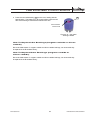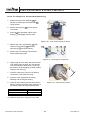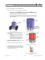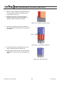
1
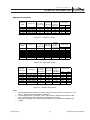
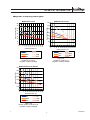
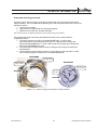
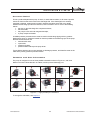
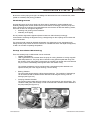
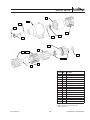
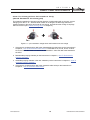
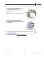
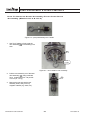
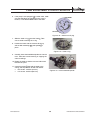
service manual
TA B L E O F C O N T E N T S
SECTION 1 CAUTIONS . . . . . . . . . . . . . . . . . . . . . . . . . . . . . . . . . . . . . . . . . . . . . . . . . . . . . . . . . . . . . . . . . . . . 3
SECTION 2 TECHNICAL INFORMATION . . . . . . . . . . . . . . . . . . . . . . . . . . . . . . . . . . . . . . . . . . . . . . . . . . 5
SECTION 3 INSTALLATION & STARTUP . . . . . . . . . . . . . . . . . . . . . . . . . . . . . . . . . . . . . . . . . . . . . . . . . 10
SECTION 4 REPAIR PARTS . . . . . . . . . . . . . . . . . . . . . . . . . . . . . . . . . . . . . . . . . . . . . . . . . . . . . . . . . . . . . . . 15
SECTION 5 SIMPLE PUMP ADJUSTMENTS . . . . . . . . . . . . . . . . . . . . . . . . . . . . . . . . . . . . . . . . . . . . . 19
SECTION 6 PUMP DISASSEMBLY & REPAIR PROCESSES
. . . . . . . . . . . . . . . . . . . . . . . . . . . . . 24
SECTION 7 TROUBLESHOOTING . . . . . . . . . . . . . . . . . . . . . . . . . . . . . . . . . . . . . . . . . . . . . . . . . . . . . . . . . 41
SECTION 8 HOW TO RETURN PUMP TO FACTORY
. . . . . . . . . . . . . . . . . . . . . . . . . . . . . . . . . . . . . 44
SECTION 9 WARRANTY . . . . . . . . . . . . . . . . . . . . . . . . . . . . . . . . . . . . . . . . . . . . . . . . . . . . . . . . . . . . . . . . . . 45
ENVIROGEAR PUMP COMPANY
2
ENV-10000-E-01
CAUTIONS
S E C T I O N
1
CAUTIONS
CAUTION: In any positive-displacement pump
system, a reliable pressure protection device
must be used in the discharge piping to avoid a
dangerous pressure increase, which could cause
the pump or any component in the discharge
piping to burst, which could cause serious injury.
A pump-mounted integral relief valve is not
intended to be used in this manner.
CAUTION: Carbon-graphite bushings are very
brittle, so they must be handled and assembled
using great care.
•
•
•
CAUTION: This pump contains powerful
permanent magnets that can cause serious injury.
Read the appropriate section of this service
manual before doing any service work.
•
Always use an arbor during assembly to
guide and align the bushings.
When pressing bushings, use a light
lubricant.
When pressing bushings, always use a
smooth, continuous motion – stopping with
the bushing partially exposed can crack the
bushing.
After assembly, always inspect the bushings
closely for cracks.
DANGER: Magnetic Field. Can disrupt medical implants such as pacemakers. Implant wearers should
remain a minimum of 1ft (0.3m) away from pump
and 3ft (1m) away from disassembled magnets.
CAUTION: You must press the bearing by its
inner ring to avoid damaging it.
Pinch Point. Inner and Outer magnets strongly attract each other which can crush and cut.
CAUTION: Failure to have each magnet segment
in opposite polarity with adjacent magnets will
cause a significant reduction of coupling torque.
CAUTION: Magnets inside pump can damage
electronic equipment or magnetic media.
CAUTION: Maximum temperature limits are
base upon mechanical stress only. Certain
chemicals will significantly reduce maximum
safe operating temperatures. Consult Chemical
Resistance Guide for chemical compatibility and
temperature limits.
CAUTION: This pump is designed to rotate only
in the direction indicated. Do not run the pump in
the opposite direction, for long periods because
internal passageways that control axial thrust
will not work correctly, causing premature wear
and reduced pumping efficiency.
CAUTION: Prevention of static sparking – if static
sparking occurs, fire of explosion could result.
Pump, valves, and containers must be grounded
to a proper grounding point when handling
flammable fluids and whenever discharge of
static electricity is a hazard.
CAUTION: The inner magnets on the back of the
rotor assembly are strongly attracted to the outer
magnets in the outer drive assembly. During the
separation process, there will be a strong force
of up to 300 lbs (136 kg) trying to pull them back
together, which can create a powerful pinch point.
CAUTION: Always wear safety glasses when
operating pump.
To safely separate the rotor assembly from the
outer drive assembly, follow the instructions
below and use the following equipment:
•
Crane, hoist or other suitable lifting device
capable of generating at least 400 lbs
(182 kg), and
•
Sturdy workbench that has the following
features:
is positioned beneath the lifting device,
and is firmly anchored to the floor, or if
unanchored, the workbench must weigh at
least 400 lbs (182 kg), and is strong enough
to resist a lifting force of up to 400 lbs (182
kg). Pump Disassembly Tool F-00096 or
F-00097.
ENV-10000-E-01
3
ENVIROGEAR PUMP COMPANY
Always read the most current version of this manual before performing any work with this pump.
The most current version is freely available on the web at www.envirogearpump.com
.
EnviroGear® pumps are specifically configured for your unique application conditions.
Those application conditions and the details of the pump configuration were documented during
the ordering process. Keep that information available in a safe place, as it may be needed when
troubleshooting pump problems or when ordering spare parts or repairs.
EnviroGear pumps are covered by one or more of the following patents: U.S. Patent Nos 7549205,
7137793, 7183683, Australian Patent No AU2005233534B2, Korean Patent No 10-2006-7023162,
Mexican Patent No PA/a/2006/011436, Russian Patent No 2006138540/06(041952) and other
patents pending.
ENVIROGEAR PUMP COMPANY
4
ENV-10000-E-01
TECHNICAL INFORMATION
S E C T I O N
2
T E C H N I C A L I N F O R M AT I O N
Models Available
Ductile Iron
Model
Std Port Size
S1-24-DI
S1-32-DI
S1-55-DI
S1-69-DI
S1-82-DI
2" NPT
2" NPT
3" ANSI 150# RF
3" ANSI 150# RF
3" ANSI 150# RF
Capacity
Max Pump
(cu. inches
Speed (rpm)
per revolution)
24.3
32.6
54.9
68.7
82.4
780
780
640
640
640
Nomimal
Flowrate
(usgpm at
max speed)
75
100
135
170
200
Pump Weight
(lb)
152
152
307
307
307
(kg)
69
69
139
139
139
Max Differential Pressure = 200 psi (13.8 bar)
Figure 2.1 – ductile iron models
Carbon Steel
Model
Std Port Size
S1-2-CS
S1-4-CS
S1-24-CS
S1-32-CS
S1-55-CS
S1-69-CS
S1-82-CS
1 1/2" NPT
1 1/2" NPT
2" NPT
2" NPT
3" ANSI 150# RF
3" ANSI 150# RF
3" ANSI 150# RF
Capacity
Max Pump
(cu. inches
Speed (rpm)
per revolution)
2.19
4.34
24.3
32.6
54.9
68.7
82.4
1800
1800
780
780
640
640
640
Nomimal
Flowrate
(usgpm at
max speed)
15
30
75
100
135
170
200
Pump Weight
(lb)
53
53
152
152
307
307
307
(kg)
24
24
69
69
139
139
139
Max Differential Pressure = 200 psi (13.8 bar)
Figure 2.2 – carbon steel models
Stainless
Steel Model
Std Port Size
S1-2-SS
S1-4-SS
S1-24-SS
S1-32-SS
S1-55-SS
S1-69-SS
S1-82-SS
1 1/2" ANSI 150# RF
1 1/2" ANSI 150# RF
2" ANSI 150# RF
2" ANSI 150# RF
3" ANSI 150# RF
3" ANSI 150# RF
3" ANSI 150# RF
Capacity
Max Pump
(cu. inches
Speed (rpm)
per revolution)
2.19
4.34
24.3
32.6
54.9
68.7
82.4
1200
1200
640
640
520
520
520
Nomimal
Flowrate
(usgpm at
max speed)
10
20
55
80
110
140
160
Pump Weight
(lb)
53
53
152
152
307
307
307
(kg)
24
24
69
69
139
139
139
Max Differential Pressure = 150 psi (10.3 bar)
Figure 2.3 – stainless steel models
Notes:
1. Recommended pump speeds may be lower than the maximum shown in Figures 2.1, 2.2
and 2.3, based on specific application conditions.
2. Pump weights shown in Figures 2.1 and 2.2 are based on standard pumps with a relief
valve. This weight will vary, depending on specific pump options.
3. EnviroGear will supply more specific flowrate values for your application conditions upon
request.
ENV-10000-E-01
5
ENVIROGEAR PUMP COMPANY
T E C H N I C A L I N F O R M AT I O N
Temperature Ratings
O-Rings Temperature Ratings
Viton®
FEP-encapsulated
Viton®
Kalrez®
-50
0
50
100
150
200
250
300
350
400
450
500
550
400
450
500
550
400
450
500
550
fluid temperature (°F)
Figure 2.4 – o-rings temperature ratings
Magnets Temperature Ratings
M6, M7
(Neodymium-Iron-Boron)
M6M, M7M
(S-C inner mags,
N-I-B outer mags)
M6H, M7H
(Samarium-Cobalt)
-50
0
50
100
150 200 250 300 350
fluid temperature (°F)
Figure 2.5 – magnets temperature ratings
Internal Clearances Temperature Ratings
standard
high-temperature
-50
0
50
100
150
200
250
300
350
fluid temperature (°F)
Figure 2.6 – internal clearances temperature ratings
ENVIROGEAR PUMP COMPANY
6
ENV-10000-E-01
T E C H N I C A L I N F O R M AT I O N
Magnetic Coupling Strengths
Models S1-2 & S1-4
80
70
300
magnet torque (ft-lb)
magnet torque (ft-lb)
Models S1-24 & S1-32
350
60
250
50
200
40
150
30
20
100
10
50
0
550
500
450
400
350
300
250
200
150
0
100
fluid temperature (°F)
50
-50
-50
0
50
100
150
200
250
300
350
400
450
500
550
0
fluid temperature (°F)
M6
M7
M6
M7
M6M
M7M
M6M
M7M
M6H
M7H
M6H
M7H
Figure 2.7
models S1-2 & S1-4
magnetic coupling strength
Figure 2.8
models S1-24 & S1-32
magnetic coupling strength
Models S1-55, S1-69 & S1-82
700
magnet torque (ft-lb)
600
500
400
300
200
100
-50
0
50
100
150
200
250
300
350
400
450
500
550
0
fluid temperature (°F)
M6
M7
M6M
M7M
M6H
M7H
Figure 2.9
models S1-55, S1-69 & S1-82
magnetic coupling strength
ENV-10000-E-01
f
7
ENVIROGEAR PUMP COMPANY
T E C H N I C A L I N F O R M AT I O N
Relief Valve Performance
Optional integral relief valves provide pump
protection from over-pressure conditions.
While not intended for continuous use,
internal relief valves protect the pump from
closed discharge valves or other intermittent
over-pressurization in the system. The
EnviroGear design is spring loaded and
contains only three parts. It addresses the
problem of over-pressurization by "cracking"
(poppet lifts off the seat) at the nominal
pressure relief setting, allowing pumped fluid
to recirculate internally from the discharge
side back to the suction side.
Figure 2.10 – relief valve
Available relief valve settings (crack
pressure):
x 50 psi (3.4 bar)
x 75 psi (5.2 bar)
x 100 psi (6.9 bar)
x 125 psi (8.6 bar)
x 150 psi (10.3 bar)
x 175 psi (12.1 bar)
x 200 psi (13.8 bar)
Model S1-32 with 100 psi valve setting
(150 cst)
125
pump flowrate (usgpm)
To maintain the integrity of the relief valve
setting, the EnviroGear relief valve is not
adjustable by means of an external jack
screw. Rather, seven relief valve settings are
fixed at the factory and adjusted by changing
the poppet and spring combinations.
780 rpm
crack
pressure
100
520 rpm
75
full bypass
pressures
50
260 rpm
25
0
0
25
50
75
100
differential pressure (psi)
125
150
Figure 2.11 – relief valve performance
To properly size the integral relief valve, it is important to understand the differences between
crack pressure and full bypass pressure.
x
Crack pressure is the pressure at which the poppet just begins to lift of the seat. This
pressure is not affected by variations in fluid viscosity or pump speed. The pump will
provide full flowrate at all pressures below the cracking pressure (see Figure 2.10).
x
Full bypass pressure is the pressure that occurs when 100% of the pump’s flowrate is
bypassing internally through the valve, and no flow is exiting the pump (see Figure 2.10).
This pressure is higher than crack pressure, and varies depending on fluid viscosity and
pump speed.
ENVIROGEAR PUMP COMPANY
8
ENV-10000-E-01
T E C H N I C A L I N F O R M AT I O N
Internal Cooling Circuit
This pump has an internal cooling circuit that circulates some of the pumped fluid through the
magnet chamber. The circuit starts at the discharge port and ends at the suction port. This circuit
has three functions:
1. cool the inner magnets,
2. keep fluid in the magnet area from becoming stagnant,
3. lubricate and cool the rotor and idler bushings.
Note: Consult factory at low differential pressures to ensure proper cooling path circulation.
There are special plugs in the casing and head that must be in the correct position to
complete the circuit:
1. The casing needs to be vented on the DISCHARGE side. In some cases,
this is done with an orifice plug that has a hole in it, positioned in the casing hole
behind the DISCHARGE port. In other cases, this is done by leaving the casing hole
behind the DISCHARGE port open.
2. The casing block-off plug is solid (no hole). It belongs in the casing hole behind the
SUCTION port.
3. The head block-off plug is solid (no hole). It is only used in pumps that have no relief
valve, and it belongs in the head hole on the DISCHARGE side.
DISCHARGE
Casing orifice
plug (with hole)
Casing block-off
plug (no hole)
DISCHARGE
Head block-off
plug (no hole)
SUCTION
This hole
left open
SUCTION
Figure 2.12 – special cooling circuit plugs in correct positions
ENV-10000-E-01
9
ENVIROGEAR PUMP COMPANY
INSTALLATION & START-UP
S E C T I O N
3
I N S TA L L AT I O N & S TA R T U P
Pump Location
It is always best to minimize suction line losses, so the best location for any pump is as close as
practical to the liquid supply source. Also, it is best to locate the pump below the liquid supply, if
practical, to maximize inlet pressure to the pump.
A proper location should leave enough room around the pump to allow for inspection or repair of
the pump without removing it from the foundation.
Pump Foundation
With any pump, a rigid foundation is essential for optimal reliability and durability. Always mount
the pump on a foundation that is rigid enough to keep the pump from moving during operation or
in the event of any stress or impact that may occur during the life of the pump. Please contact
EnviroGear for more information on premium EnviroBase base plates.
ENVIROGEAR PUMP COMPANY
10
ENV-10000-E-01
I N S TA L L AT I O N & S TA R T U P
Pressure Relief
This is a positive-displacement pump. As such, for each shaft revolution, it will move a specific
volume of fluid from the suction side to the discharge side. If the discharge line is severely
restricted or blocked, a dangerous increase in pressure and drive torque will occur rapidly
between the discharge port and the restriction, which will lead to one or more of the following
events:
x the pipe or other discharge line components bursts,
x the drive stalls,
x the pump’s inner and outer magnets decouple,
x a pump component breaks.
A reliable pressure protection device must be used in the discharge piping with any positivedisplacement pump. It should be located as close as possible to the discharge port of the pump.
Several common devices are:
x external relief valve,
x rupture disc,
x pressure regulator,
x pressure switch that stops the pump driver.
Torque limiting devices cannot react precisely to discharge pressure, and therefore must not be
used as the primary pressure protection device.
Rotation and Port Orientation
The pump is configured in one of the 8 possible orientations shown in Figure 3.1, and it has
labels on it which indicate direction of rotation, suction port and discharge port.
TL
RT
TR
LT
LB
BR
LR
BL
RB
RL
Figure 3.1 – eight possible port orientations
To change the orientation, see Chapter 5.
ENV-10000-E-01
11
ENVIROGEAR PUMP COMPANY
I N S TA L L AT I O N & S TA R T U P
Piping
Excessive pipe stress can cause reduced pump durability and reliability by affecting shaft
alignment and/or distorting pump components. Isolate the pump from any pipe stress. Here are
several suggestions that help isolate the pipe stress:
x Properly support all piping with suitable pipe hangars or supports, not with the pump.
x Install flexible lines near the pump.
x If the pumped liquid will be hot, be sure to calculate pipe expansion and provide
provisions for it.
All discharge piping components must be designed to safely handle the maximum system
pressure.
Make sure all the pipes and other components are clean before installation.
A reliable pressure protection device must be used in the discharge piping with this positivedisplacement pump. See section Pressure Relief above for more details.
Pressure gauges are valuable tools for troubleshooting pump-related problems. Install gauges
near both pump ports (some pumps have gauge ports for this purpose). Also install gauges on
both sides of high-restriction components, such as filters, heat exchangers or flowmeters.
Remember, it is much easier to include gauges when the piping is first installed than to add
gauges later.
Suction Piping
The suction piping must be able to supply liquid to the pump at the desired flowrate with sufficient
pressure at the pump to avoid cavitation. To ensure this, you should calculate the NPSHa
(available) for the suction piping design and compare it to the NPSHr (required) value for the
pump – the piping NPSHa must be greater than the pump NPSHr to avoid cavitation. Here are
several suggestions that help maximize suction piping NPSHa:
x Locate the pump below the liquid supply.
x Keep the suction piping short.
x Use large diameter piping. The difference in pipe friction between small and large pipe
sizes can be dramatic, especially for high viscosities.
x Avoid high restriction components, such as filters, heat exchangers or flowmeters. Try to
install these components in the discharge piping instead.
x Be sure to consider the full range of operating conditions, especially the highest viscosity
conditions. Changes in viscosity can have a dramatic effect on pipe friction.
If your suction piping requires a long run and a rise (pump is higher than the liquid level at the
supply), it is best to keep most of the run at the lower level, and position the rise as close to the
pump as possible. This allows gravity to fill most of the piping.
If your suction piping must detour around an obstacle, it is best to go around it instead of over it.
This lowers the vacuum needed for priming.
If your suction has a lift and it can drain back to the supply between runs, consider using a foot
valve or check valve. This will keep the suction line filled between runs and ease priming. But be
sure the valve is large enough that it doesn’t cause excessive restriction (lowers NPSHa).
Consider using a strainer to protect the pump from any contaminant particles that could be
present in the liquid. Be sure the strainer is properly sized so it doesn’t cause excessive
restriction (lowers NPSHa).
ENVIROGEAR PUMP COMPANY
12
ENV-10000-E-01
I N S TA L L AT I O N & S TA R T U P
Be sure the suction piping is air-tight. Air leakage into the suction line can cause low flow, noise
(similar to cavitation) and priming problems.
Shaft Alignment
Accurate alignment of the pump shaft and driver shaft is essential for optimal reliability and
durability. Misalignment causes vibrations that reduce the life of bearings in both the pump and
driver, and the life of couplings. Final shaft alignment must be done AFTER the following events,
since both of them can change the alignment:
x Mounting and grouting of the foundation.
x Assembly of the piping.
Use of precision alignment equipment (based on lasers or dial indicators) is strongly
recommended. Checking the alignment using a straight-edge on the couplings is inaccurate and
not recommended.
For pumps that will operate at elevated temperature, the alignment at room temperature will
change as the pump warms. Be sure to measure or calculate this effect and adjust the alignment,
so that it is accurate at operating temperature.
Pump Condition Monitoring
There are several pump conditions that can be monitored:
t
Canister Temperature.
Heat is generated in the canister when the pump is running because of moving magnetic
fields that pass thru it. The pump has an internal cooling path that pulls heat away from
the canister. If this cooing path is obstructed, the canister and magnet area could become
very hot, which could damage the magnets and/or the canister o-ring.
The canister temperature can be monitored with a temperature probe attached to an
optional access port in the magnet housing, near the casing.
x
Bearing Vibration:
The pump shaft is supported by rolling-element bearings. The condition of the bearings
can be monitored with a vibration sensor attached to the magnet housing, near the
bearings (see Figure 3.3).
x
Pumping Chamber Vibration:
The pumping gears rotate within the casing and are supported by journal bushings. The
condition of the gears and bushings can be monitored with a vibration sensor attached to
the pump head (see Figure 3.4).
Location for
Canister
Temperature
Sensor
Location for
Pumping
Chamber
Vibration
Sensor
Location for
Bearing
Vibration
Sensor
Figure 3.3 – optional sensor locations
ENV-10000-E-01
Figure 3.4 – optional sensor locations
13
ENVIROGEAR PUMP COMPANY
I N S TA L L AT I O N & S TA R T U P
Startup
Before starting the pump, follow this procedure:
1. Thoroughly clean the pump, pipes and other components. Note: In most cases, the pump
is shipped clean of any contaminants, except for a thin layer of lubricant on the spindle
and bushing surfaces. In some other cases, the pump will contain residual petroleum oil
from the factory testing. EnviroGear can provide more details for your specific pump upon
request.
2. Verify that the piping components are all tightened and in their final position.
3. Ensure the pressure relief device is installed and working correctly.
4. Verify that the shaft alignment is correct (see Shaft Alignment section above).
5. Verify that the pump freely turns by hand.
6. Verify that the driver rotates the pump shaft in the correct direction.
7. Open or close all valves in the suction piping to ensure that liquid will reach the pump.
8. Open or close all valves in the discharge piping to ensure that liquid will reach the
intended location.
9. If the suction is not flooded, add a small volume of compatible liquid into the pump. This
will improve the priming ability and lubricate the pump during a dry startup.
10. Verify that all guards and other safety equipment is installed and working correctly.
11. If the driver includes a gearbox, check the manual from the gearbox manufacturer to
confirm that the lubricant is at the proper level, and for any additional startup procedures
related to the gearbox.
Now the pump is ready to be started.
Once started, check the following:
x Is the pump moving liquid? If it doesn’t within 60 seconds, stop the pump. See
Troubleshooting section to help solve the problem.
x Are there any leaks in the piping? If so, stop the pump and fix them.
x Are there any unusual noises or vibrations? If so, stop the pump. See Troubleshooting
section to help solve the problem.
x Is the pump performing as expected (proper flowrate and pressure)? If not, see
Troubleshooting section to help solve the problem.
ENVIROGEAR PUMP COMPANY
14
ENV-10000-E-01
REPAIR PARTS
S E C T I O N
4
R E PA I R PA R T S
Repair Parts
The parts used in this pump are designed and manufactured with exacting tolerances, material
specifications and production techniques. Always use authentic repair parts supplied by
EnviroGear® or its authorized selling partners. Use of any other parts may void the
pump’s warranty.
This EnviroGear® pump was specifically configured for your unique application conditions.
conditions. EnviroGear® can supply a detailed bill of material that includes the part numbers
for your specific pump configuration (identified by serial number). Use these part numbers when
ordering repair parts.
ENV-10000-E-01
15
ENVIROGEAR PUMP COMPANY
R E PA I R PA R T S
7
6
100
10
200
4
8
400
14
5
2
11
12
9
3
300
1
13
Part ID # Qty.
1
1
2
1
3
1
4
1
5
1
6
1
7
1
8
1
9
4
10
4
11
1
12
1
13
2
14
1
100
1
200
1
300
1
400
1
Part Name
Head
Casing
Spindle
O-Ring for Canister*
O-Ring for Head*
Canister
Support Plate
Key
Bolts for Head
Bolts for Outer Drive
Orifice Plug
Plug for Casing
Plugs for Vent/Drain
Plug for Head
Outer Drive Assembly
Rotor Assembly
Idler Assembly
Relief Valve Assembly
*Recommened spares.
ENVIROGEAR PUMP COMPANY
16
ENV-10000-E-01
R E PA I R PA R T S
102
101
103
108
104**
105
106
105
201
202
204
203**
207
208
208
206
205
Part ID # Qty. Part Name
101
1
Magnet Housing
102
1
Outer Ring
103
1
Shaft
104
** Magnet Segment
105
2
Ball Bearing
106
1
Wave Spring
107
Adhesive (not shown)
108
1
Retaining Ring
201
1
Rotor
202
1
Inner Ring
203
** Magnet Segment
204
1
Sleeve
205
1
O-Ring for back of sleeve
206
1
O-Ring for front of sleeve
207*
1
Thrust Bushing
208*
2
Radial Rotor Bushing
*Recommened spares.
**Magnet quantities may vary depending on
pump configuration.
ENV-10000-E-01
17
ENVIROGEAR PUMP COMPANY
R E PA I R PA R T S
302
301
402
404
401
405
403
501
502
505
504
503
Part ID # Qty. Part Name
301
1
Idler
302
1
Idler Busing*
401
1
Valve Body
402
1
Poppet
403
2
Spring
404
1
O-Ring for Valve*
405
4
Screws for Valve
501
1
Jacket for Casing
502
1
Jacket for Valve
503
1
Jacket Brackets
504
4
Screws
505
2
Screws
506
Thermal Cement (not shown)
601
1
Jacket for Head
602
1
O-Ring for Jacket*
603
4
Screw for Jacket
601
603
602
*Recommened spares.
ENVIROGEAR PUMP COMPANY
18
ENV-10000-E-01
SIMPLE PUMP ADJUSTMENTS
S E C T I O N
5
SIMPLE PUMP ADJUSTMENTS
How To Change Port Orientation Only
(Shaft Rotation Unchanged)
This instruction applies for changes when the direction of shaft rotation will not change, such as
changing from “RT to “TL”. Since the shaft rotation is unchanged, the discharge and suction
positions relative to the casing and head will not change, and therefore the cooling circuit plugs
will not be moved (see “Internal Cooling Circuit” in Chapter 2).
Æ
TL
RT
Figure 5.1 – port orientation change when shaft rotation does not change
1. If the pump is equipped with a relief valve, disassemble the relief valve per the instructions in
Chapter 6, “How To Disassemble Relief Valve”. For Models S1-24, S1-32, S1-55, S1-69 or
S1-82, the relief valve does not need to be disassembled – leave the relief valve attached to
the head.
2. Disassemble pumping chamber per the instructions in Chapter 6, “How To Disassemble
Pumping Chamber”.
3. Assemble pumping chamber in the new orientation per the instructions in Chapter 6, “How To
Assemble Pumping Chamber”.
4. If the pump is equipped with a relief valve, assemble relief valve per the instructions in
Chapter 6, “How To Assemble Relief Valve”.
ENV-10000-E-01
19
ENVIROGEAR PUMP COMPANY
SIMPLE PUMP ADJUSTMENTS
How To Change Port Orientation And Shaft Rotation
This instruction applies for changes when the direction of shaft rotation will change, such as
changing from “RT to “LT”. Since the shaft rotation will change, the discharge and suction
positions relative to the casing and head will also change, and therefore the cooling circuit plugs
must be moved (see “Internal Cooling Circuit” in Chapter 2).
Æ
RT
LT
Figure 5.2 – port orientation change when shaft rotation changes
1. If the pump is equipped with a relief valve, disassemble the relief valve per the instructions in
Chapter 6, “How To Disassemble Relief Valve”.
2. Disassemble pumping chamber per the instructions in Chapter 6, “How To Disassemble
Pumping Chamber”.
ENVIROGEAR PUMP COMPANY
20
ENV-10000-E-01
SIMPLE PUMP ADJUSTMENTS
3. Remove the casing orifice plug 11 (not used on all
configs) and casing block-off plug. 12
11
DISCHARGE
4. Install the casing orifice (if required) plug behind the
DISCHARGE port.
SUCTION
5. Install the casing block-off plug behind the SUCTION
port.
12
Figure 5.3 – Casing plugs
6. If the pump is not equipped with a relief valve,
remove the head block-off plug 14 and move it to the
DISCHARGE side.
DISCHARGE
14
SUCTION
Figure 5.4 – head block-off plug
7. Assemble pumping chamber in the new orientation per the instructions in Chapter 6, “How To
Assemble Pumping Chamber”.
8. If the pump is equipped with a relief valve, assemble relief valve in the new orientation per
the instructions in Chapter 6, “How To Assemble Relief Valve”.
ENV-10000-E-01
21
ENVIROGEAR PUMP COMPANY
SIMPLE PUMP ADJUSTMENTS
How To Change Relief Valve Pressure Setting
In order to maintain the integrity of the relief valve setting, the EviroGear relief valve is not
externally adjustable. Instead, the setting is adjusted by changing the poppet and/or spring.
1. Obtain a new poppet and/or spring for the desired relief valve setting.
(Consult factory for assistance)
2. Disassemble relief valve per the instructions in Chapter 6, “How To Disassemble Relief
Valve”.
3. Reassemble the relief valve using the new poppet and/or spring per the instructions in
Chapter 6, “How To Assemble Relief Valve”.
ENVIROGEAR PUMP COMPANY
22
ENV-10000-E-01
SIMPLE PUMP ADJUSTMENTS
How To Change Relief Valve Pressure Setting
In order to maintain the integrity of the relief valve setting, the EviroGear relief valve is not
externally adjustable. Instead, the setting is adjusted by changing the poppet and/or spring.
1. Obtain a new poppet and/or spring for the desired relief valve setting.
(Consult factory for assistance)
2. Disassemble relief valve per the instructions in Chapter 6, “How To Disassemble Relief
Valve”.
3. Reassemble the relief valve using the new poppet and/or spring per the instructions in
Chapter 6, “How To Assemble Relief Valve”.
ENV-10000-E-01
23
ENVIROGEAR PUMP COMPANY
PUMP DISASSEMBLY & REPAIR PROCESSES
S E C T I O N
6
P U M P D I S A S S E M B LY & R E PA I R P R O C E S S E S
How To Disassemble Relief Valve
1. Remove the screws 405 that hold the valve
body 401 to the head 1 . It is normal for the
valve spring 403 to push the valve body
away from the head during this step – the
spring will be fully relaxed just before the
screws are fully removed.
1
2. Remove the valve body, spring, poppet
and o-ring 404 .
401
405
Figure 6.1 – valve body removal
9
404
403
401
405
402
Figure 6.2 – disassembled relief valve
ENVIROGEAR PUMP COMPANY
24
ENV-10000-E-01
P U M P D I S A S S E M B LY & R E PA I R P R O C E S S E S
How To Disassemble Pumping Chamber
1. Remove the screws
casing 2 .
9
that hold the head
1
to the
2. Remove the head.
Note: when the head or spindle is removed, the
pump will be difficult to turn by hand. This is normal.
2
1
3. Remove the head o-ring
5
from the head.
5
Figure 6.3 – head removed
4. Remove the idler assembly
spindle 3 .
300
by sliding it off the
200
5. Pull the spindle out of the rotor assembly
200 .
300
3
Figure 6.4 – idler and spindle
removed
6. Remove the screws 10 that hold the outer drive
assembly 100 to the casing.
100
7. Separate the casing and outer drive assembly.
8. Remove the canister o-ring
casing.
4
from its groove in the
Figure 6.5 – casing removed
ENV-10000-E-01
25
ENVIROGEAR PUMP COMPANY
P U M P D I S A S S E M B LY & R E PA I R P R O C E S S E S
How To Remove Rotor Assembly From Outer Drive
Assembly (Models S1-2 & S1-4)
Figure 6.6 – pump disassembly tool F-00097
1. Use Tool F-00097 to firmly grab the
rotor assembly 200 in the bushing bore
area.
200
Tool
F-00097
Figure 6.7 – tool inserted in rotor assembly
2. Pull the rotor assembly out of the outer
drive assembly 100 , using moderate
force. It takes about 40 – 60 pounds
of force (18 – 27 kg).
100
3. Remove the tool and set the rotor
assembly aside, away from any
magnetic material (e.g. steel, iron).
ENVIROGEAR PUMP COMPANY
26
ENV-10000-E-01
P U M P D I S A S S E M B LY & R E PA I R P R O C E S S E S
4. Remove the canister 6 (containing the
support plate 7 ) from the outer drive
assembly.
6
7
Figure 6.9 – canister removed
ENV-10000-E-01
27
ENVIROGEAR PUMP COMPANY
P U M P D I S A S S E M B LY & R E PA I R P R O C E S S E S
How To Remove Rotor Assembly From Outer Drive
Assembly (Models S1-24, S1-32, S1-55, S1-69 & S1-82)
Figure 6.10 – pump disassembly tool F-00096
1. Attach the puller plate to the rotor assembly
of the pump’s 1/2"-13 screws 9 or 10 .
200
using three
200
puller
plate
9 or 10
Figure 6.11 – puller plate
attached
2. Loosely fit the two rods into opposite holes on the outer drive
assembly 100 .
channel
rod
3. Loosely position the two rod ends into the channel.
4. Twist the two rods to tighten the channel nuts, which locks
the rods to the channel.
Figure 6.12 – rods and channel
attached
ENVIROGEAR PUMP COMPANY
28
ENV-10000-E-01
P U M P D I S A S S E M B LY & R E PA I R P R O C E S S E S
5. Assemble the two wing nuts onto the two rods to hold them to
the outer drive assembly.
wing nut
6. Carefully lift the outer drive assembly (with the tool kit
attached) and set it on a suitable workbench vertically, with
the rotor teeth facing up.
7. Firmly affix the channel to the workbench surface, so that it
can safely resist a lifting force of up to 400 lbs (182 kg).
Firmly affix to
workbench
Figure 6.13 – tool fully
assembled
8. Slowly pull the rotor assembly up and away from the outer
drive assembly, using a crane, hoist or other suitable lifting
device.
9. Remove the puller plate and set the rotor assembly aside,
away from any magnetic material (e.g. iron, steel).
Figure 6.14 – pull rotor
assembly up
10. Remove the canister 6 (containing the support plate 7 ) from
the outer drive assembly.
6&7
Figure 6.15 – remove canister
ENV-10000-E-01
29
ENVIROGEAR PUMP COMPANY
P U M P D I S A S S E M B LY & R E PA I R P R O C E S S E S
How To Replace Idler Bushings (carbon-graphite)
1. Remove the old bushing 302 by pressing it
out of the idler 301 . It is not unusual for
the bushing to crack or break apart during
removal.
These surfaces
must be flush
(both sides)
302
2. Inspect the idler bore for any damage. Any
small scratches or nicks must be filed
smooth before installing the new bushing.
3. Press the new idler bushing into the idler,
leading with the tapered edge. The
bushing is in its proper location when both
ends of the bushing are flush or slightly
recessed from the idler faces.
301
Figure 6.16 – idler assembly
How To Replace Rotor Bushings (carbon-graphite)
1. Remove the old bushings 207 208 by pressing them out of the rotor
the bushings to crack or break apart during removal.
201 .
It is not unusual for
2. Inspect the rotor bore for any damage. Any small scratches or nicks must be filed smooth
before installing the new bushings.
3. Press the front radial bushing 208 into the rotor, leading with the
tapered edge. The bushing is in its proper location when the front
face of the bushing is flush with the nearest rotor face.
201
208
These surfaces
must be flush
Figure 6.17 – front
radial bushing installed
4. Press the thrust bushing 207 into the rotor, leading with the
tapered edge, until it bottoms out.
207
Figure 6.18 – thrust
bushing installed
ENVIROGEAR PUMP COMPANY
30
ENV-10000-E-01
P U M P D I S A S S E M B LY & R E PA I R P R O C E S S E S
5. Press the rear radial bushing 208 into the rotor, leading with the
tapered edge. The bushing is in its proper location when the rear
face of the bushing is flush with the nearest rotor face.
208
These surfaces
must be flush
Figure 6.19 – rear radial
bushing installed
How To Replace Idler Bushings (tungsten carbide or silicon
carbide)
Due to the brittle nature of tungsten carbide and silicon carbide bushings, we recommend they
be replaced in the EnviroGear factory.
How To Replace Rotor Bushings (tungsten carbide or
silicon carbide)
Due to the brittle nature of tungsten carbide and silicon carbide bushings, we recommend they
be replaced in the EnviroGear factory.
ENV-10000-E-01
31
ENVIROGEAR PUMP COMPANY
P U M P D I S A S S E M B LY & R E PA I R P R O C E S S E S
How To Replace Outer Ball Bearing
1. Position the outer drive assembly 100 on
blocks in a suitable press with the shaft 103
facing upward.
2. Remove the snap ring
in the shaft.
108
108
103
105
from its groove
100
3. Press the shaft downward until the outer
bearing 105 disengages from the shaft.
Figure 6.20 – outer drive assembly on blocks
4. Remove the outer ring assembly 102 (with
shaft and inner bearing 105 attached),
wave spring 106 and outer bearing.
105
102
106
105
108
5. Remove the inner bearing from the shaft
with a suitable gear puller.
Figure 6.21 – bearing area components
6. Apply a light oil to the shaft, and press the new
inner bearing onto the shaft. The new bearing
inner race should be flush with the outer ring.
Be careful to avoid disrupting the shaft position,
relative to the outer ring.
D
7. Insert the wave spring into the inner bearing
counterbore of the magnet housing.
8. Insert the outer ring/shaft/inner bearing
assembly into the magnet housing.
9. Press the outer bearing onto the shaft until the
distance from the end of the shaft to the face of
the bearing meets the following specification:
Model
S1-2, S1-4
S1-24, S1-32, S1-55, S1-69
S1-82
Figure 6.22 – outer bearing location
distance “D”
1.898“ (48.21 mm)
2.536“ (64.41mm)
3.911“ (99.34 mm)
10. Install the snap ring in its groove in the shaft.
ENVIROGEAR PUMP COMPANY
32
ENV-10000-E-01
P U M P D I S A S S E M B LY & R E PA I R P R O C E S S E S
How To Replace Inner Magnets
1. There are two methods to remove the sleeve from the rotor.
a. Support the rotor assembly 200 on the front edge of the sleeve 204 , with the teeth
facing down. Leave at least 1 inch (25 mm) of clearance beneath the teeth. Then
press the rotor down, separating it from the sleeve.
b. Carefully cut the sleeve as shown in Figure 6.24. Be careful to avoid damaging the
rotor in the area around the front o-ring. The sleeve will easily pull off the rotor after
this cut is in place.
cut
204
204
Do not damage
rotor in the front
o-ring area.
Figure 6.23 – method a
2. Remove the old magnet segments 203 from the
inner ring 22022 .
a. In most cases, the magnets are held in
place only by their magnetic attraction to
the inner ring.
b. In a few other cases, they are held in
place with epoxy. Contact PeopleFlo
EnviroGearfor
for
instructions for removing the epoxy.
3. Remove the front 2206 and rear
from the grooves in the rotor.
2205
Figure 6.24 – method b
205
202
206
203
sleeve o-rings
4. Install new o-rings in the grooves in the rotor.
Figure 6.25 – sleeve removed
5. Slowl
net se
ment
Slowly brin
bring one end of a new ma
magnet
segment
into contact with the end of one flat on the inner
ring, such that only a short length of the magnet is
in contact with the inner ring.
Figure 6.26 – assembling magnet
segments
ENV-10000-E-01
33
ENVIROGEAR PUMP COMPANY
P U M P D I S A S S E M B LY & R E PA I R P R O C E S S E S
6. Slide the magnet segment along the length of the
inner ring until it touches the small stop at the
front end of the inner ring.
7. Repeat steps 5 and 6 for the other magnet
segments, making sure that each magnet is in
opposite polarity with adjacent magnets.
Figure 6.27 – magnet in proper position
8. Align the new sleeve over the back of the rotor
such that the sleeve indentations are lined up with
the magnets.
aligned
Figure 6.28 – proper sleeve alignment
9. Press the sleeve over the magnets and o-rings
until it contacts the rear of the inner ring.
10. Visually inspect the front and rear of the sleeve to
verify that the o-rings did not get damaged by the
sleeve.
Figure 6.29 – assembled rotor
ENVIROGEAR PUMP COMPANY
34
ENV-10000-E-01
P U M P D I S A S S E M B LY & R E PA I R P R O C E S S E S
How To Install Rotor Assembly Into Outer Drive Assembly
(Models S1-2 & S1-4)
1. Insert the canister 6 and support plate 7 into the outer
drive assembly 100 . The support plate has no “top”
or “bottom”, so it’s orientation doesn’t matter.
100
2” (5 cm)
2. Use Tool F-00097 to firmly grab the rotor assembly
200 in the bushing bore area.
6&7
3. Bring the rotor assembly toward the canister until the
back of the rotor is about 2 inches (5 cm) from the
front of the outer drive assembly.
100
Tool
F-00097
Figure 6.30 – tool in rotor assembly
4. Slowly let the outer magnets pull the rotor into the
canister, while using moderate resisting force. The
pulling force is about 40 – 60 pounds (18 – 27 kg).
5. Remove the puller tool.
Figure 6.31 – rotor assembly in place
ENV-10000-E-01
35
ENVIROGEAR PUMP COMPANY
P U M P D I S A S S E M B LY & R E PA I R P R O C E S S E S
How To Install Rotor Assembly Into Outer Drive Assembly
(Models S1-24, S1-32, S1-55, S1-69 & S1-82)
1. Loosely fit the two rods into opposite holes on the outer
drive assembly 100 .
channel
rod
100
2. Loosely position the two rod ends into the channel.
3. Twist the two rods to tighten the channel nuts and clamp
the rods to the channel.
Figure 6.32 – rods and channel
assembled
4. Assemble the two wing nuts onto the two rods to hold
them to the outer drive assembly.
wing nut
5. Carefully lift the outer drive assembly (with the tool kit
attached) and set it on a suitable workbench vertically,
with the rotor teeth facing up.
6. Firmly affix the channel to the workbench surface, so that
it can safely resist a lifting force of up to 400 lbs (182 kg).
Firmly affix to
workbench
Figure 6.33 – outer drive
assembly mounted to tool
7. Insert the canister 6 (containing the support plate 7 ) into
the outer drive assembly. The support plate has no “top”
or “bottom”, so its orientation doesn’t matter.
6&7
Figure 6.34 – insert canister and
support plate
ENVIROGEAR PUMP COMPANY
36
ENV-10000-E-01
P U M P D I S A S S E M B LY & R E PA I R P R O C E S S E S
8. Attach the puller plate to the rotor assembly
three of the pump’s 1/2"-13 screws 9 or 10 .
200
using
9 or 10
puller
plate
200
Figure 6.35 – puller plate on rotor
assembly
9. Support the rotor assembly using a crane, hoist or other
suitable lifting device, and position it above the canister,
about 4 inches (10 mm) from the front of the outer drive
assembly.
4” (10 cm)
100
Figure 6.36 – rotor assembly
ready for lowering
10. Slowly lower the rotor assembly into the canister.
Note: During this process, the inner magnets on the rotor
assembly will be strongly attracted to the outer magnets
in the outer drive assembly.
Figure 6.37 – rotor assembly in
place
ENV-10000-E-01
37
ENVIROGEAR PUMP COMPANY
P U M P D I S A S S E M B LY & R E PA I R P R O C E S S E S
11. Carefully lift the outer drive assembly (with the tool kit
attached) and set it on a workbench, resting on the pump
foot.
12. Remove the tool rods and puller plate.
Figure 6.38 – remove tool
How To Assemble Pumping Chamber
1. Make sure the casing orifice plug and casing blockoff plug are in the correct locations:
t
Install the casing orifice plug (if required) 11
behind the DISCHARGE port.
t
Install the casing block-off plug 12 behind the
SUCTION port.
11
2. Position the canister o-ring 4 in its groove in the
casing 2 . If necessary, use a small amount of light
adhesive to keep the o-ring properly positioned.
DISCHARGE
12
SUCTION
3. Slide the casing over the rotor 200 , the lip of the
canister 6 and magnet housing 101 . It may take
some wiggling of the casing to get the canister and
magnet housing positioned within the casing’s
alignment counterbore.
4
2
Figure 6.39 – casing plugs and o-ring
4. If necessary, rotate the casing to get the ports in the
preferred position.
5. Insert the screws 10 that hold the outer drive assembly 100 to the casing.
a. First, torque them to 5-10 ft-lbs (7-14 N-m) in an alternating pattern.
b. Next, torque them to 20 ft-lbs (27 N-m) in an alternating pattern.
c. Finally, torque them to their final values in an alternating pattern:
t
3/8” screws: 40 ft-lbs (54 N-m).
t
1/2" screws: 65 ft-lbs (88 N-m).
ENVIROGEAR PUMP COMPANY
38
ENV-10000-E-01
P U M P D I S A S S E M B LY & R E PA I R P R O C E S S E S
6. If the pump is not equipped with a relief valve, make
sure the head block-off plug 14 is in the correct
location, on the DISCHARGE side of the head.
DISCHARGE
14
SUCTION
Figure 6.40 – head block-off plug
7. Slide the head o-ring 5 onto the head 1 . Take
care to avoid scratching the o-ring.
1
8. Position the head with the crescent facing up,
and set idler assembly 300 and spindle 3 in
place.
5
Figure 6.41 – head o-ring
9. Carefully insert the head/idler/spindle unit into the
rotor. Take care to avoid cracking or chipping the
carbon bushings.
3
300
10. Rotate the head so that the rotor and idler mesh
between the ports.
11. Insert the screws 9 that hold the head to the
casing, and torque them to their final values:
x 3/8” screws: 40 ft-lbs (54 N-m).
x 1/2" screws: 65 ft-lbs (88 N-m).
ENV-10000-E-01
Figure 6.42 – insert head/idler/spindle
39
ENVIROGEAR PUMP COMPANY
P U M P D I S A S S E M B LY & R E PA I R P R O C E S S E S
How To Assemble Relief Valve
1. Check the valve body o-ring 404 for
damage, and replace it if necessary.
2. Position the valve body o-ring in its groove
in the valve body 401 . If necessary, use a
small amount of light adhesive to keep the
o-ring properly positioned.
3. Position the spring
the valve body.
403
1
404
and poppet inside
4. Determine which pocket in the head 1 is
aligned with the discharge port. The relief
valve poppet 402 must be positioned on
the discharge pocket for the valve to
function correctly.
402
405
401
Figure 6.43 –relief valve assembly
5. Position the valve body/spring/poppet onto the pump head, with the poppet over the
discharge pocket, and loosely assemble the valve body screws.
6. Tighten the screws in an alternating pattern until the valve body is fully contacting the head.
Torque the screws to to their final values:
x 3/8” screws: 40 ft-lbs (54 N-m).
x 1/2" screws: 65 ft-lbs (88 N-m).
ENVIROGEAR PUMP COMPANY
40
ENV-10000-E-01
TROUBLESHOOTING
S E C T I O N
7
TROUBLESHOOTING
Symptom or Problem: Pump is excessively noisy.
Possible Cause(s):
x Air in the inlet fluid stream.
x Relief valve is opening.
x Pump has decoupled.
x Pump components are damaged or worn.
x Pump is cavitating.
x Discharge line is too restrictive.
x Cooling path is plugged.
x Ball bearings are worn or damaged.
Symptom or Problem: Pump does not prime.
Possible Cause(s):
x Discharge line is too restrictive.
x Suction lift is too great.
x Pump is not wetted.
x Air leak in the suction line.
x Pump is running in the wrong direction.
x Head is positioned incorrectly.
x Cooling path plugs are not installled.
x Pump is locked up with hardened fluid or foreign items.
x Pump components are damaged or worn.
x Pump has decoupled.
x Inner magnets have weakened.
x Cooling path is plugged.
x Relief valve is stuck open.
Symptom or Problem: Flowrate is too low.
Possible Cause(s):
x Head is positioned incorrectly.
x Cooling path plugs are not installled.
x Discharge line is too restrictive.
x Viscosity is lower than expected.
x Air in the inlet fluid stream.
x Pump is cavitating.
x Relief valve is opening.
x Pump components are damaged or worn.
x Bypass or auxiliary line in the discharge piping is open.
x Cooling path is plugged.
x Relief valve is stuck open.
ENV-10000-E-01
41
ENVIROGEAR PUMP COMPANY
TROUBLESHOOTING
Symptom or Problem: Pump does not develop enough pressure.
Possible Cause(s):
x Air in the inlet fluid stream.
x Viscosity is lower than expected.
x Pump is cavitating.
x Relief valve is opening.
x Pump components are damaged or worn.
x Bypass or auxiliary line in the discharge piping is open.
x Head is positioned incorrectly.
x Cooling path plugs are not installled.
x Cooling path is plugged.
x Relief valve is stuck open.
Symptom or Problem: Relief valve does not open.
Possible Cause(s):
x Pump is running in the wrong direction.
x Relief valve is stuck closed.
Symptom or Problem: Leakage from head/casing area.
Possible Cause(s):
x O-ring material is not compatable with the pumped fluid.
x Sealing surfaces for the o-rings are damaged.
x Bolt(s) are loose or missing.
x O-ring is damaged or missing.
Symptom or Problem: Leakage from casing/magnet housing area.
Possible Cause(s):
x O-ring material is not compatable with the pumped fluid.
x Sealing surfaces for the o-rings are damaged.
x Casing or magnet housing mounting flanges are cracked.
x Bolt(s) are loose or missing.
x O-ring is damaged or missing.
Symptom or Problem: Leakage from head/valve body area.
Possible Cause(s):
x O-ring material is not compatable with the pumped fluid.
x Sealing surfaces for the o-rings are damaged.
x Bolt(s) are loose or missing.
x O-ring is damaged or missing.
Symptom or Problem: Leakage from drive shaft area.
Possible Cause(s):
x Canister is damaged and leaking.
Symptom or Problem: Excessive vibration.
Possible Cause(s):
x Air in the inlet fluid stream.
x Relief valve is opening.
x Pump has decoupled.
x Pump components are damaged or worn.
x Pump is cavitating.
x Ball bearings are worn or damaged.
x Inner magnets have weakened.
x Cooling path is plugged.
ENVIROGEAR PUMP COMPANY
42
ENV-10000-E-01
TROUBLESHOOTING
Symptom or Problem: Pump draws too much power.
Possible Cause(s):
t
Pump components are damaged or worn.
t
Relief valve is stuck closed.
t
Ball bearings are worn or damaged.
t
Viscosity is higher than expected.
ENV-10000-E-01
43
ENVIROGEAR PUMP COMPANY
HOW TO RETURN PUMP TO FACTORY
S E C T I O N
8
HOW TO RETURN PUMP TO FACTORY
If a pump must be returned to the EnviroGear factory, a Return Goods Authorization (RGA) must
be obtained from EnviroGear or its authorized distributor. No RGA can be issued without a
review of the appropriate Material Safety Data Sheets (MSDS). Pumps must be cleaned of all
fluids and the ports plugged to prevent foreign material from getting into the pump.
ENVIROGEAR PUMP COMPANY
44
ENV-10000-E-01
WARRANTY
S E C T I O N
9
WARRANTY
EnviroGear warrants that on the day of delivery, all products manufactured by it shall be free from
defects in materials and workmanship. For a period twenty four (24) months from the date of
shipment EnviroGear will, at its sole and exclusive discretion, either replace or repair any products
found by EnviroGear to be defective in workmanship or material, at no charge to the Purchaser.
The warranty does not apply to:
t
t
t
t
any products which have been modified or altered by persons other than EnviroGear; or
any products subjected to any misuse, neglect, misapplication, improper installation or
accidental damage; or
any goods manufactured by a third party; or
any products damaged by the effects of abrasion, erosion or corrosion.
No returns will be accepted by EnviroGear unless accompanied by EnviroGear’s written authorization
and EnviroGear will assume no field expense for service or parts unless authorized in writing by
EnviroGear in advance. All warranty replacement or repairs must be performed by EnviroGear or a
EnviroGear Authorized Service Organization.
EnviroGear assumes no liability for consequential damages of any kind and the purchaser, by
acceptance of delivery, assumes all liability for the consequences of the use or misuse of EnviroGear
products by the purchaser, the purchaser’s employees or others.
This warranty is exclusively for the benefit of the first purchaser of the product, other than a
purchaser for resale, and cannot be transferred or assigned.
THERE SHALL BE NO OTHER WARRANTY, EXPRESS OR IMPLIED, INCLUDING ANY
IMPLIED WARRANTY OF MERCHANTABILITY OR FITNESS FOR A PARTICULAR PURPOSE
OR ANY OTHER OBLIGATION ON THE PART OF ENVIROGEAR WITH RESPECT TO PRODUCTS
EXCEPT THE WARRANTY OR WARRANTIES CONTAINED HEREIN.
ENV-10000-E-01
45
ENVIROGEAR PUMP COMPANY
22069 Van Buren Street • Grand Terrace, CA 92313-5607
Phone: (909) 422-1731 • Fax: (909) 783-3440
website: www.enviropump.com
Printed in the U.S.A.
Copyright 2011 EnviroGear Pump Company
ENV-10000-E-01