1
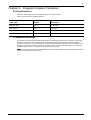
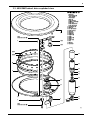
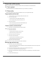
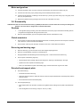
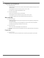
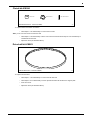
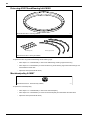
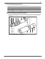
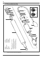
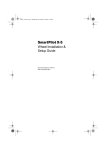
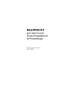
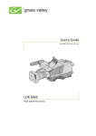
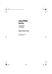
S1 Tiller and Wheel Pilot
Service Manual
Document Number: 83187_1
Date: January 2007
i
Contents
ST6002 control head .............................................................................................................. 1
Disassembly/Assembly............................................................................................ 1
ST6002 spare parts list............................................................................................ 2
Fluxgate Compass Transducer ............................................................................................ 1
Functional test ......................................................................................................... 1
Magnetic deviation................................................................................................... 1
4000 MK2 wheel drive ............................................................................................................ 3
4000 MK2 wheel drive test ...................................................................................... 3
Spares for 4000 Mk2 wheel drive ............................................................................ 4
4000 MK2 wheel drive exploded view ..................................................................... 5
Tools required.......................................................................................................... 6
Disassembly ............................................................................................................ 6
Reassembly............................................................................................................. 7
Adjusting the clutch ................................................................................................. 9
Cleaning the wheel drive ......................................................................................... 9
Fitting spares and accessories .............................................................................. 10
Tiller Drive Actuator ............................................................................................................ 17
Tiller Drive Actuator test ........................................................................................ 17
Disassembly/assembly .......................................................................................... 18
Tiller Drive Actuator GP ...................................................................................................... 21
Tiller Drive Actuator GP test .................................................................................. 21
Disassembly/assembly .......................................................................................... 22
ii
1A
Fascia with flat window
1
Fascia with curved window
3 (Note D)
3A
2
5A
2
17 (Note A) 4 (Note D) 5 (Note D)
Pips Horizontal rib
7 (x2)
8 (Note B)
Notes:
A. Earlier production units have a shim (17) fitted to
aid keypad compression.
B. The castellated top edge of the diffuser (8) fits under
the legs of the LEDs on the top edge ofthe PCB (10).
C. It is recommended that a new case seal (12) is fitted
on reassembly.
D. Only fitted on units with CURVED window to fascia.
6
E12025 and E12100
Light Grey Flush Mount Control Unit
1B
9
10
1.
1A.
1B.
2.
3.
3A.
4.
5.
5A.
6.
7.
11 (x3)
Torque to
0.33 Nm
(3 lb in)
Fascia (dark grey)
Fascia (light grey)
Flush mount fascia (light grey)
Keypad
Label (old profile)
Label (latest profile)
Window insert
LCD surround
LCD surround
LCD
Elastomer strip (x2)
12 (Note C)
8.
9.
10.
11.
12.
13.
14.
15.
16.
17.
14
11 (x8)
Torque to
0.33 Nm
(3 lb in)
15
D4586-2
Diffuser
Reflector
PCB
Retaining screw (x11)
Case seal
Rear cover
Buzzer connector
Back cover label (ST6000+/ST6001+)
Bulkhead gasket
Keypad shim (earlier units only)
13
16
1
Chapter 1: ST6002 control head
1.2 Disassembly/Assembly
Note: This drawing above is not an exact representation of the present plastics. Following this process will show
you how to separate the plastics and seals to replace the PCB as there are no serviceable parts with this item. It is
just a case of replacing the PCB if any problems are present
2
1.2 ST6002 spare parts list
Below is a table populated with Spare parts for the ST6002 as there are no serviceable parts with this product it is
just a case of dismantling the unit and replacing the internal PCB.
Spare Part Number
Description
A18012-P
Universal Pilot Display Kit
A18018-P
ST6002 Surface Mount Fascia Kit
A18090-P
ST6002 Spare PCB Assembly
A25004-P
ST60+ Surface Mount Sun Cover
Q219
ST4/5/6001 & 6002 Autopilot Keypad
W118
ST4/5/6001 & 6002 Case Seal
W119-P
ST6002 Back Cover Assembly
1
Chapter 2: Fluxgate Compass Transducer
2.2 Functional test
Disconnect the Fluxgate from the Autopilot and check continuity as follows:
Cable color connector pin number Resistance
Cable Color
Connector Pin
Number
Resistance
Screen to blue
(2/4)
< 10 ohms
Red to green
(3/5)
< 5 ohms
Red to yellow
(3/6)
< 5 ohms
Red to screen
(3/2)
Open circuit
2.2 Magnetic deviation
The Fluxgate Compass requires careful siting if optimum Autopilot performance is to be achieved. The SeaTalk
electronics is able to correct the compass for most deviating magnetic fields present when the linearization
procedure is carried out. Any further deviation, introduced after linearization, will introduce an error between the
Fluxgate and the ship’s compass. This can be removed by carrying out the linearization again. If the displayed
deviation is greater than +/– 15 degrees the Fluxgate should be re-sited.
Note: The linearization procedure should always be carried out if the Fluxgate has been exchanged, removed or
moved from its original mounting position.
2
Disassembly/assembly
1
2
4
7
8
3
6
1. Cover
2. Seal
3. Pivot retaining screw (x2)
4. Bracket
5. Pivot sub-assembly
5
9
6. Fluxgate sub-assembly
7. Body
8. Body screw (x4)
9. Cable
D3726-2
Figure 4. Fluxgate Compass exploded view
Fluxgate Compass spare parts list
The item numbers refer to Figure 4: Fluxgate Compass exploded view
Item
Spare Description
Part No.
Compass base kit, including
M096
3
Pivot retaining screw (x2)
4
Bracket
Fluxgate sub-assembly, including
5
Pivot sub-assembly (x2)
6
Fluxgate sub-assembly
M022
Comments
3
Chapter 3: 4000 MK2 wheel drive
Introduction
This manual explains the service and maintenance procedures for the Raymarine 4000 Mk2 wheel drive unit.
3.1 4000 MK2 wheel drive test
Note: For information about servicing the ST4000+ control unit and fluxgate compass, refer to the ST4000 Plus
Autopilots Service Manual (83115-3)
Start
Switch on. With clutch engaged,
check drive ring moves and
current is less than 2 A
Remove front cover and
visually inspect unit
OK
OK
No
Change damaged components
No
Check gears, belt tension,
eccentrics, drive lever, motor
Yes
Change/adjust as necessary
Yes
Rotate drive ring by hand
with clutch disengaged
OK
No
Yes
Check drive ring rotates freely
and belt does not drag
Restrain drive ring rotation until
6.5 A is obtained. Check that belt
does not slip.
OK
Change/adjust as necessary
No
Yes
Reverse polarity of supply
Check resistance across
motor connector pins is
approximately 1 to 2 ohms
OK
No
Switch on. Check drive ring
moves in opposite direction
to that of first test and
current is less than 2 A
Check wiring and connector
OK
Yes
Change as necessary
No
Yes
Check gears, belt tension,
eccentrics, drive lever, motor
Change/adjust as necessary
Check motor
Change as necessary
Restrain drive ring rotation until
6.5 A is obtained. Check that belt
does not slip.
OK
No
Yes
Connect power supply (see below)
Drive unit OK. End of test.
D5728-1
12 A
Fuse/CB
Switch
PSU
12 V 15 A
D5727-1
4
3.2 Spares for 4000 Mk2 wheel drive
Item
Spare/Accessory
Front cover
Part No.
1
–
24
Front cover
6 mm drill bit
Back cover
11
Drive ring
Clutch lever
A18077
7
6
Clutch lever
M5 x 30 mm screw
Clutch ratchet knob
A18078
9
6
Ratchet knob
M5 x 30 mm screw
Support plate
A18079
3
2
Support plate
M5 x 8 mm screw (x2)
Torque restraint (pedestal bracket)
A18080
–
–
–
–
Torque restraint
No 10 x ¾ inch screw (x4)
4 mm drill bit
Wheel drive unit
4
Drive belt
A18074
Not illustrated on exploded view
A18075
A18076
Not illustrated on exploded view
Not illustrated on exploded view
Not illustrated on exploded view
Clutch kit
A18081
A18083
A18084
8
5
6
Clutch eccentric
Clutch roller
M5 x 30 mm screw
Bearing kit
A18085
12
10
18
Ball bearings (x21)
Bearing cage (x3)
Motor
13
Machined pulley
23
Gearbox
Single spoke clamp
Spoke clamp
16 mm spoke clamp insert
12 mm spoke clamp insert
M5 x 16 mm screw
3 mm allen key
Motor loom and seal kit
A18092
14
15
19
20
21
22
Collar nut
Rubber cap
Motor clamp
O-ring
Loom plug assembly
Gasket
Power cable
A18061
end and connector spades at the
other
Entire wheel drive assembly
A18086
A18087
A18088
A18089
–
–
–
–
–
4.5 m (15 ft) cable with plug at one
Comments
Not illustrated
Not illustrated
Not illustrated
Not illustrated
Not illustrated
with
with
with
with
with
exploded unit
exploded unit
exploded unit
exploded unit
exploded unit
Not illustrated with exploded unit
5
3.3 4000 MK2 wheel drive exploded view
4000 Mk2 Wheel Drive
/01 2 2 3
! " # $ ! ! % ! ! &
# '( ( (
' ( !) *
+ " $ % # ,-(
.
'& # $
%
#
"
%
$
" /01 2 2 3
$-
6
Disassembly and Reassembly
Note: The numbered parts in the following instructions refer to the annotations on the exploded views.
3.4 Tools required
To assemble/disassemble the 4000 Mk2 wheel drive unit you will need a 3 mm allen key.
3.5 Disassembly
Remove the wheel drive from the wheel and release the clutch, then complete these steps:
Support plate and drive belt
1.
Remove the front cover (1) by pulling it away from the back cover.
2.
Remove the support plate:
•
unscrew and remove the 2 support plate screws (2)
•
lever the support plate (3) away from the back cover
3.
Remove the drive belt:
•
lever the drive belt (4) up and over the machined pulley (13)
•
remove the drive belt from the drive ring (11)
Clutch eccentrics, knob and lever
4.
Remove the 2 clutch rollers (5) from the clutch eccentrics.
Note: the clutch rollers are identical.
5.
Remove the clutch lever:
•
unscrew and remove the clutch lever screw (6)
•
pull the clutch lever (7) off the back cover
6.
Remove the clutch lever eccentric (8).
7.
Remove the clutch ratchet knob:
•
unscrew and remove the ratchet knob screw (6)
•
pull the ratchet knob (9) off the back cover
8.
Remove the clutch knob eccentric (8).
Note: the clutch lever eccentric and clutch knob eccentric are identical.
Bearing cage and drive ring
9.
Remove the 3 parts of the bearing cage (10):
•
insert one end of the allen key into the joint between 2 parts of bearing cage (10), then lever one part of the
cage up so you can pull it out
10. Push all of the ball bearings together. The drive ring (11) will then be free to move.
11. Hold the drive unit horizontal, then lift off the drive ring (11).
12. Remove the 21 ball bearings (12), taking care to retain them for reassembly (e.g. in the inside of upturned
front cover).
13. Lift off the machined pulley (13).
7
Motor and gearbox
14. Unscrew the plastic collar nut (14) by turning it anti-clockwise, then remove the rubber cap (15).
15. Unscrew the motor tube (16) by hand (turning it anti-clockwise) and then remove it.
16. Lift off the motor assembly, consisting of: motor sleeve (17), motor (18), motor clamp (19), O-ring (20), motor
loom (21) and gasket (22).
17. Remove the gearbox (23) by pushing it out from the rear of the back cover (24).
3.6 Reassembly
CAUTION: Do NOT use mineral-based solvents (e.g. WD40) to lubricate or clean the wheel drive as they will damage the
material. The wheel drive is designed to run without lubrication.
Gearbox
1.
Fit the gearbox (23) by inserting it from the inside of the back cover (24). Ensure that the locating slots on
the gearbox are aligned with the lugs in the back cover.
2.
Place the machined pulley (13) onto the gearbox shaft, with the recessed face on top.
Clutch eccentrics
3.
Fit the 2 clutch eccentrics (8) with their flanges downwards, so that they are clear of the foul pins on the back
cover. Note: the 2 clutch eccentrics are identical.
4.
Fit the 2 clutch rollers (5) over the clutch eccentrics. Note: the 2 clutch rollers are identical.
Drive ring and bearing cage
5.
Place the drive ring (11) onto the back cover, with its lipped edge uppermost.
6.
Place the 21 ball bearings (12) back into the ball groove.
7.
Roughly distribute the ball bearings around the ball groove – this should secure the drive ring.
8.
Fit the 3 parts of the bearing cage (10):
•
clip the first part of the bearing cage into the ball groove, capturing 7 ball bearings in the cage
•
repeat for the other 2 parts of the bearing cage
•
when you have fitted the 3 parts of the bearing cage, check that the drive ring is free to rotate
Drive belt and support plate
9.
Fit the drive belt (4):
•
Fit the belt around the drive ring
•
rotate the clutch eccentrics to make the maximum amount of space between the machined pulley and the
clutch eccentrics
•
then fit the belt around the machined pulley
10. Fit the support plate (3):
•
fit the support plate over the clutch eccentrics and gearbox shaft, making sure the plate is pressed down
fully
•
insert and tighten the 2 screws (2): torque to 12 lb.in (1.4 Nm)
8
Clutch lever and ratchet knob
11. Fit the clutch lever (7):
•
place the clutch lever onto the eccentric spindle (it should be positioned between the two pips on the rear
of the back cover)
•
insert and tighten the clutch lever screw (6): torque to 12 lb.in (1.4 Nm)
•
check that the lever engages and disengages the clutch
12. Fit the clutch ratchet knob (9):
•
place the clutch ratchet knob over the eccentric spindle
•
insert and tighten the clutch ratchet knob screw (6): torque to 12 lb.in (1.4 Nm)
•
you will need to adjust the clutch after reassembling the wheel drive (Section 3.4)
Motor assembly
13. Fit the motor assembly:
•
carefully insert the gear at the end of the motor (18) into the hole on the gearbox (23), making sure the
teeth engage properly
•
also make sure that the pin on the motor engages into one of the 2 holes on the top of the gearbox
•
check that the O-ring seal (20) is still sitting on the motor clamp
14. Fit the motor tube (16):
•
place it over the motor and hand-tighten it onto the back cover
15. Fit the rubber cap (15) and secure it with the plastic collar nut (14), making sure the lip on the collar nut is
uppermost.
Front cover
16. Fit the font cover (1):
•
line up the arrow on the front cover with the arrow on the drive ring, then press the cover into place
9
3.7 Adjusting the clutch
Clutch knob
screw
Clutch knob
Loosen the screw
(2 turns)
D5349-2
Adjusting the clutch
To loosen
the clutch
(4 clicks)
To tighten
the clutch
(4 clicks)
1
2
Tighten the screw
(2 turns)
3
You need to adjust the clutch if you have removed the clutch eccentrics, replaced the ratchet knob, or replaced the
drive belt. When the clutch is correctly adjusted:
•
the drive ring can rotate freely when the clutch is disengaged
•
the drive belt does not slip when the clutch is engaged and the motor is driving
To adjust the clutch, make sure the clutch is disengaged. Then:
1.
Use a 3 mm allen key to loosen the clutch knob screw about 2 turns anti-clockwise.
2.
Turn the clutch knob either 4 clicks clockwise to tighten the clutch, or 4 clicks anti-clockwise to loosen the
clutch.
3.
Use the allen key to re-tighten the clutch knob screw.
4.
Check that the wheel still moves freely with the clutch off.
Note: If the wheel does not move freely, reduce the clutch tension by turning the clutch knob 2 clicks anti-clockwise
and check again
5.
Check the drive’s operation with the clutch engaged.
This procedure is usually sufficient to correct a slipping or dragging drive belt. In some cases, however, you may
need to repeat the steps to adjust the clutch further.
3.8 Cleaning the wheel drive
CAUTION: Do NOT use mineral-based solvents (e.g. WD40) to lubricate or clean the wheel drive as they will damage the
material. The wheel drive is designed to run without lubrication.
•
To clean the wheel drive front/rear cover: use a mild detergent if necessary, then flush thoroughly with
fresh water.
•
To clean inside the wheel drive: if there is a build-up of salt on the wheel drive bearings and drive belt, thoroughly flush the wheel drive interior with fresh water.
10
3.9 Fitting spares and accessories
Clutch lever A18077
Clutch lever
M5 x 30 mm screw
4000 Mk2 Wheel Drive - Clutch Lever (A18077)
D5734-2
To replace the clutch lever:
•
follow step 5 of ‘Disassembly’ to remove the lever
•
follow step 11 of ‘Reassembly’ to fit the new lever
Clutch ratchet knob A18078
Clutch ratchet knob
M5 x 30 mm screw
4000 Mk2 Wheel Drive - Clutch Ratchet Knob (A18078)
D5735-2
To replace the clutch ratchet knob:
•
Follow step 7 of ‘Disassembly’ to remove the knob
•
follow step 12 of ‘Reassembly’ to fit the new knob
•
adjust the clutch (as described above)
Support plate A18079
Support plate
M5 x 8 mm screw (x2)
4000 Mk2 Wheel Drive - Support Plate (A18079)
To replace the support plate:
•
Follow steps 1-2 of ‘Disassembly’ to remove the support plate
•
follow step 10 of ‘Reassembly’ to fit the new support plate
•
fit the front cover
D5736-2
11
Clutch kit A18084
Clutch roller
Clutch eccentric
4000 Mk2 Wheel Drive - Clutch Kit (A18084)
M5 x 30 mm screw
D5740-2
To replace either of the clutch eccentrics:
•
follow steps 1-8 of ‘Disassembly’ to remove the eccentric:
Note: you do not need to remove the drive belt
•
follow steps 3-4 of ‘Reassembly’ to fit the new eccentric and then follow steps 9-12 of ‘Reassembly’ to
reassemble the drive unit
•
adjust the clutch (as described above)
Drive belt kit A18083
4000 Mk2 Wheel Drive - Drive Belt (A18083)
D5739-2
To replace the drive belt:
•
follow steps 1-3 of ‘Disassembly’ to remove the old drive belt
•
follow steps 9-10 of ‘Reassembly’ to fit the replacement drive belt and then the support plate
•
fit the front cover
•
adjust the clutch (as described above)
12
Drive ring A18076 and Bearing kit A18085
4000
4000 Mk2
Mk2 Wheel
Wheel Drive
Drive -- Drive
Drive Ring
Ring (A18075)
(A18075)
Ball bearing (x21)
D5733-2
D5733-2
Bearing cage (3 parts)
4000 Mk2 Wheel Drive - Bearing Kit (A18081)
D5741-2
To replace the drive ring and/or ball bearings and/or bearing cage:
•
follow steps 1-12 of ‘Disassembly’ to remove the ball bearings, bearing cage and drive ring
•
follow steps 5-16 of ‘Reassembly’ to fit the new drive ring and/or bearing cage and/or ball bearings, and
reassemble the wheel drive
•
adjust the clutch (as described above)
Machined pulley A18087
4000 Mk2 Wheel Drive - Machined Pulley (A18087)
D5743-2
To replace the machined pulley:
•
follow steps 1-13 of ‘Disassembly’ to remove the machined pulley
•
follow steps 2-16 of ‘Reassembly’ to fit the new machined pulley and reassemble the wheel drive
•
adjust the clutch (as described above)
13
Gearbox A18088
4000 Mk2 Wheel Drive - Gearbox (A18088)
D5744-2
To replace the gearbox:
•
follow all of the ‘Disassembly’ steps to remove the gearbox
•
follow all of the ‘Reassembly’ steps to fit the new gearbox and reassemble the wheel drive
•
adjust the clutch (as described above)
Motor A18086
4000 Mk2 Wheel Drive - Motor (A18086)
D5742-2
To replace the motor:
•
follow steps 14-16 of ‘Disassembly’ to remove the motor assembly
•
lift up the motor clamp so you can de-solder the motor loom wires from the contacts on the motor
•
solder the motor loom wires to the new motor
•
follow steps 13-15 of ‘Reassembly’ to fit the new motor assembly
Motor loom and seal kit A18092
Motor clamp
O-ring
Motor loom
(with wires attached)
Seal
Collar nut
Rubber cap
4000 Mk2 Wheel Drive - Motor Loom and Seal Kit (A18092)
D5746-2
To replace the motor loom:
•
follow steps 14-16 of ‘Disassembly’ to remove the motor assembly
•
lift up the motor clamp so you can de-solder the motor loom wires from the contacts on the motor
•
solder the new loom wires to the motor terminals
•
follow steps 13-15 of ‘Reassembly’ to fit the motor assembly
14
Front cover A18074
4000 Mk2 Wheel Drive Front Cover (A18074)
D5731-2
To replace front cover:
•
pull off the old front cover
•
drill the relevant spoke clamp holes in the new front cover
•
fit the front cover back onto the drive unit
For more details, refer to the instructions supplied with the cover.
Rear cover A18075
4000 Mk2 Wheel Drive - Back Cover (A18075)
To replace the rear cover:
•
follow all of the disassembly steps
•
follow all of the reassembly steps
D5732-2
15
Wheel drive unit A18081
4000 Mk2 Wheel Drive Unit (A18081)
D5738-2
Torque restraint A18080
4 mm drill bit
Torque restraint
No10 x 3/4 in screw (x4)
4000 Mk2 Wheel Drive - Torque Restraint (A18080)
D5737-2
Fit according to instructions supplied with the torque restraint.
Single spoke clamp A18089
M5 x 16 mm
screw (x2)
Spoke clamp insert
12 mm
Spoke clamp
Spoke clamp insert
16 mm
3 mm allen key
4000Mk2 Wheel Drive - Single Spoke Clamp (A18089)
Fit according to instructions in ST4000+ Wheel and Tiller Autopilots Owner’s Handbook.
D5745-2
16
17
Chapter 4: Tiller Drive Actuator
4.1 Tiller Drive Actuator test
Carry out the passive and active tests detailed in Figure 11. Tiller Drive Actuator test flowchart.
Blue
Fuse/CB
12A
1
2
3
Brown
Blue
Switch
Brown
Actuator deck plug
PSU
12V 15A
D2394-2
Figure 10. Tiller Drive Actuator test connections
Start
Connect power supply
as in Figure 10.
Visually inspect unit
No
OK
Change damaged
components
Yes
Switch on,
check thrust rod moves and
current less than 2.5A
Extend and retract
thrust arm by hand
OK
No
OK
Yes
Check gears,
thrust rod,
actuator body,
motor
Change
as necessary
Check resistance across
motor connector pins 2 and 3
is approximately 1 to 2 ohms
OK
No
Check wiring
and connector
Yes
OK
No
Yes
Change
as necessary
Switch off.
Reverse connections to PSU
Switch on.
Check thrust rod moves
in opposite direction
to that of first test and
current less than 2.5A
No
Yes
Check motor
Check gears,
thrust rod,
actuator body,
motor
OK
No
Yes
Check gears,
thrust rod,
actuator body,
motor
Change
as necessary
Change as
necessary
Actuator OK.
End of test
D3728-2
Figure 11. Tiller Drive Actuator test flowchart
9. Flux ring
10. Motor sleeve
11. End cap assembly
12. Cable clamp
13. Clamp seal
14. Cable clamp nut
15. SeaTalk deck plug
1
Notes:
A. Ensure cable clamp nut (14) is unscrewed before
undoing the motor sleeve.
B. The hole in the gear annulus (7) that accepts the
drive gear of the motor (8) is of a different diameter
to that of the ST4000+ GP gear annulus.
C. Care should be taken not to cross-thread the
annulus (7) when screwing into the thrust tube (2).
1. Ram cap
2. Thrust tube
3. Lead screw assembly
4. Planet gear (x4)
5. Shim
6. 'O' ring (x3)
7. Gear annulus
8. Motor (Q114)
8
9
2
10
15
6
11
3
Figure 12. Tiller Drive Actuator exploded view
14
Note A
7
Notes B & C
ST4000+ GP
16mm diameter
End view of Annulus (7)
13
5
ST4000+
13mm diameter
12
4 (x4)
6
6
D2395-2
18
4.2 Disassembly/assembly
19
Tiller Drive Actuator spare parts list
The item numbers refer to Figure 12: Tiller Drive Actuator exploded view
Item
Spare Description
Part No.
Comments
Drive module
Q047
Complete drive unit
8
Motor
Q114
11
End cap assembly
W014
Tiller Drive Actuator GP conversion kit (W003)
This GP conversion kit (W003) gives the option of converting the ST4000+ which has the power to helm boats of up
to 6,500 kg (14,300 lbs) displacement, to the ST4000+ GP which would push the limit up to 9,000 kg (20,000 lbs)
displacement.
1
2
3
4
3
5
6
7
1. Planet gear (x4)
2. Shim
3. 'O' ring (x3)
4. Gear annulus
5. Motor
6. Motor spacer
7. Cable tie
8. Motor sleeve
9. End cap assembly
8
3
9
D2397-2
Figure 13. Tiller Drive Actuator GP conversion kit (W003)
20
21
Chapter 5: Tiller Drive Actuator GP
5.1 Tiller Drive Actuator GP test
Carry out the passive and active tests detailed in Figure 15. Tiller Drive Actuator GP test flowchart.
Blue
Fuse/CB
12A
1
2
3
Brown
Blue
Switch
Brown
Actuator deck plug
PSU
12V 15A
D2398-2
Figure 14. Tiller Drive Actuator GP test connections
Start
Connect power supply
as in Figure 10.
Visually inspect unit
No
OK
Change damaged
components
Yes
Switch on,
check thrust rod moves and
current less than 2A
Extend and retract
thrust arm by hand
OK
No
OK
Yes
Check gears,
thrust rod,
actuator body,
motor
Change
as necessary
Check resistance across
motor connector pins 2 and 3
is approximately 1 to 2 ohms
OK
No
Check wiring
and connector
Yes
OK
No
Yes
Change
as necessary
Switch off.
Reverse connections to PSU
Switch on.
Check thrust rod moves
in opposite direction
to that of first test and
current less than 2A
No
Yes
Check motor
Check gears,
thrust rod,
actuator body,
motor
OK
No
Yes
Check gears,
thrust rod,
actuator body,
motor
Change
as necessary
Change as
necessary
Actuator OK.
End of test
D3731-2
Figure 15. Tiller Drive Actuator GP test flowchart
9. Cable tie
10. Motor spacer
11. Motor sleeve
12. End cap assembly
13. Cable clamp
14. Clamp seal
15. Cable clamp nut
16. SeaTalk deck plug
1
Notes:
A. Ensure cable clamp nut (15) is unscrewed before
undoing the motor sleeve.
B. The hole in the gear annulus (7) that accepts the
drive gear of the motor (8) is of a different diameter
to that of the ST4000+ gear annulus.
C. Care should be taken not to cross-thread the
annulus (7) when screwing into the thrust tube (2).
1. Ram cap
2. Thrust tube
3. Lead screw assembly
4. Planet gear (x4)
5. Shim
6. 'O' ring (x3)
7. Gear annulus
8. Motor
8
9
10
2
11
16
6
12
3
Figure 16. Tiller Drive Actuator GP exploded view
5
14
15
Note A
7
Notes B & C
ST4000+
13mm diameter
ST4000+ GP
16mm diameter
End view of Annulus (7)
13
4 (x4)
6
6
D2396-2
22
5.2 Disassembly/assembly
23
Tiller Drive Actuator GP spare parts list
The item numbers refer to Figure 16: Tiller drive actuator GP exploded view
Item
Spare Description
Part No.
Comments
Drive module
Q086
Complete drive unit
ST4000+ GP kit, including
W003
Serves as an upgrade
4
Planet gear (x4)
conversion kit for the
5
Shim
ST4000+ tiller drive
6
‘O’ ring (x3)
actuator.
7
Annulus
8
Motor
9
Cable tie
10
Motor spacer
11
Motor sleeve
12
End cap assembly
24