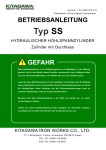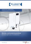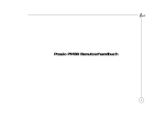
1
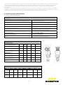
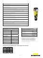
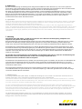
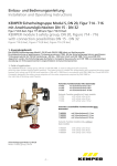
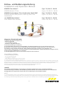
Einbau- und Bedienungsanleitung
Installation and Operation Manual
KEMPER Filter Modul F
KEMPER Module F Filter
Figur 712, DN 15 – DN 50
Figure 712, DN 15 – DN 50
KEMPER Druckminderer-Filter-Kombination Modul DMF
KEMPER Module DMF pressure reducing valve-Filter
combination
Figur 713, DN 15 – DN 50
Figure 713, DN 15 – DN 50
mit KEMPER Basis-Modul
with KEMPER Basic Module
Figur 700, DN 15 – DN 50
Figure 700, DN 15 – DN 50
Allgemeine Sicherheitshinweise
1. Benutzen Sie den Druckminderer nur:
- bestimmungsgemäß
- in einwandfreiem Zustand
- sicherheits- und gefahrenbewusst.
2. Die Einbauanleitung ist zu beachten.
3. Zur sachgemäßen Verwendung ist sicherzustellen, dass die Druckminderer nur dort zum Einsatz kommen, wo
Betriebsdruck und Temperatur die bei der Bestellung zugrunde gelegten Auslegungskriterien nicht überschreiten.
Für Schäden, die durch äußere Kräfte oder andere äußere Einwirkungen entstehen, ist der Hersteller nicht
verantwortlich! Gefährdungen, die am Druckminderer vom Durchflussmedium und dem Betriebsdruck ausgehen können,
sind durch geeignete Maßnahmen zu verhindern.
4. Alle Montagearbeiten sind durch autorisiertes Fachpersonal durchzuführen.
General Notes of Safety
1. Only use the pressure reducer:
- for the specified purpose
- in satisfactory condition
- with respect for safety and potential hazards.
2. Always observe the installation instructions.
3. To ensure correct use always make sure to only install the pressure reducer in places where the operating pressure and
temperature do not exceed the design criteria on which the order is based. The manufacturer shall not be responsible for
damage caused by outside forces or other external influences! Hazards at the pressure reducer caused by the flow
medium and operating pressure are to be avoided through appropriate measures.
4. All assembly work is to be carried out by authorized specialist staff.
HINWEIS
Wir empfehlen die Neuinstallation und Durchführung der Wartungsarbeiten durch einen autorisierten Fachbetrieb.
Um eine Verkeimung zu verhindern, sollte die Wartung und der Austausch von Innenteilen der Armatur nur mit desinfizierten
Einweghandschuhen vorgenommen werden. Diese sind im Lieferprogramm der Ersatzteile enthalten.
NOTE
It is recommended to have a new installation and maintenance work carried out by an authorized expert workshop. In
order to avoid bacterial contamination, the maintenance and replacement of the valve inner parts should only be carried
out wearing disinfected disposable gloves. Those gloves are available within the delivery program of spare parts.
-1-
KEMPER Filter Modul F
KEMPER Module F Filter
Filter Modul F Figur 712
Module F Filter Figur 712
als Funktions-Modul Größe I
as Function-Module size I
als Funktions-Modul Größe II
as Function-Module size II
Basis-Modul Figure 700 G
Basic Module Figure 700 G
für Basis-Modul DN 15 bis DN 25 (32) oder
for Basic-Module DN 15 to DN 25 (32) or
für Basis-Modul DN 32 bis DN 50
for Basic-Module DN 32 to DN 50
1. Anwendungsbereich
Der rückspülbare Filter Modul F ist nach DIN EN 13443-T1 (ehemals DIN 19632) geprüft und wurde für den Einsatz als
Filter-Armatur für Trinkwasserinstallationen nach DIN 1988 konstruiert.
Die lt. DIN 1988 regelmäßig vorzunehmende Rückspülung wird bei Zusetzen des Filters (z. B. durch Schwebteilchen oder
Rückstände im Wasser) durch eine differenzdruckgesteuerte Rückspülanzeige signalisiert. Der Einbau des Filter Modul F
in die Rohrleitung erfolgt zusammen mit dem KEMPER Basis-Modul Figur 700. Er kann bei Bedarf optional zur
Druckminderer-Filter-Kombination Modul DMF nachgerüstet werden, indem anstelle der werkseitig montierten
Überströmkappe ein Druckminderer-Modul Figur 710 montiert wird.
Aus hygiene- und funktionstechnischer Sicht ist der Filter nicht im Bereich Eigenwasserversorgungsanlagen einzusetzen.
1. Scope of use
The back-flush filter Module F is tested according to DIN EN 13443-T1 (before19632) and it has been designed for use as
a filter valve for drinking water installations according to DIN 1988.
The back-flushing to be carried out regularly according to DIN 1988 is at filter clogging (e. g. through floating particles
or rests in water) signalled by means of pressure difference controlled back-flush indicator. The Module F filter is
mounted into a piping system together with the KEMPER Basic Module Figure 700. In case of need it can be optionally
added to the Module DMF pressure reducing valve-filter combination, so that instead of the overflow cap mounted at
works the pressure reducing valve module Figure 710 is added.
For hygienic and functional-technical reasons the filter cannot be used at self-managed water supply equipment.
2. Montage
siehe hierzu die Explosionszeichnung unter Punkt 8
Der Filter Modul F Figur 712 wird mit dem Basis-Modul Figur 700 (Position B) verbunden und spannungsfrei bei
Beachtung der auf dem Basis-Modul gekennzeichneten Fließrichtung in die Rohrleitung eingebaut. Um einen
einwandfreien und bestimmungsgemäßen Betrieb zu gewährleisten, muss der Einbau des Filters in allen Fällen
senkrecht mit dem Auslauf nach unten erfolgen.
Der nach DIN EN 1717 konstruierte Auslauf des Filters ist bei Vorhandensein einer Abwasserleitung an die Kanalisation
anzuschließen. Empfehlenswert ist die Installation eines Bodenablaufes im Bereich des Filters, um ein automatisches
Ablaufen des bei der Rückspülung anfallenden Wassers zu gewährleisten. Vor der Inbetriebnahme des Filters ist die
Leitung vor dem Filter ausreichend zu spülen.
2. Mounting
see the isometric exploded assembly under 8
-2-
The Filter Module F Figure 712 is to be connected with the Basic Module Figure 700 (Position B) and stress-free mounted
into the piping. Attention has to be paid to the flow direction marked on the basic module. In order to guarantee a
problem-free, purposeful operation, the filter has to be mounted vertically in all cases, with the outlet pointing
downwards.
The filter outlet designed according to DIN EN 1717 is to be connected to sewerage if waste-water piping is available.
Installation of a floor inlet within the range of the filter is recommended in order to assure automatic flowing-off of the
water arisen at back-flushing. The pipe has to be flushed before the commissioning of the filter.
3. Ausführung und Technische Daten
3. Design and Technical Data
3.1 Ausführung
3.1 Design
KEMPER Rückspülfilter nach DIN EN 13443- T1
KEMPER back-flush filter according to DIN EN 13443-T1
Filtereinsatz:
Filter sleeve:
Trennschärfe:
Filter efficiency
Materialeigenschaften Filtertasse:
Filter plate material properties:
Kunststoffteile:
Plastic parts:
Mediumberührte Innenteile:
Inner parts being in contact with drinking water:
Rotgusskomponenten:
Components of gunmetal:
ABP-Nr:.
ABP No.
als manueller Rückspülfilter
as a manual back-flush filter
aus nichtrostenden Stahlgewebesegmenten
made of stainless steel wire fabric segments
72%
72%
stoßfest, glasfaserverstärkter Kunststoff
impact resistant, glass fibre reinforced plastic
aus schlagfestem Thermoplast
made of impact resistant thermoplastic
aus Rotguss, Edelstahl und hochwertigem Kunststoff
made of gunmetal, stainless steel and high-quality plastic
entsprechend DIN 50930-6
according to DIN 50930-6
P-IX: 7938/I (DN 15-25), 6732/I (DN 32)
P-IX: 7938/I (DN 15-25), 6732/I (DN 32)
3.2 Maße
3.2 Dimensions
Nennweite
Nominal inside diameter
Bauhöhe (H1)
built-in height (H1)
Bauhöhe (H2)
built-in height (H2)
Bautiefe (T1)
built-in depth (T1)
Bautiefe (T2)
built-in depth (T2)
Baulänge (L1)
built-in length (L1)
Ablauf-Durchmesser (D)
outflow diameter (D)
Gewicht
weight
DN
32
40
50
mm
15 - 25
(32)
324
471
471
471
mm
276
384
384
384
mm
114
142
142
142
mm
53
67,5
67,5
67,5
mm
105
145
145
145
mm
50
50
50
50
kg
3,0
4,8
4,8
4,8
3.3 Hydraulische Daten: Durchfluss bei Δp = 0,2 bar, Δp = 1,0 bar
3.3 Hydraulic Data: Rate of flow at Δp = 0,2 bar, Δp = 1,0 bar
DN
15
2,3
20
3,0
25
3,3
32 (Gr 1)
3,3
32 (Gr. 2)
6,8
40
7,5
50
9,0
Δp = 0,5
3,0
4,6
5,0
5,0
11,8
12,0
14,5
Q (m³/h)
Δp = 1,0
Q (m³/h)
4,3
6,8
7,2
7,2
17,0
18,5
20,9
Δp = 0,2
Q (m³/h)
-3-
3.4 Technische Eigenschaften
3.4 Technical data
mediumberührte Innenteile aus Rotguss, Edelstahl und hochwertigem Kunststoff
inside parts being in contact with drinking water made of gunmetal, stainless steel
and high-quality plastic
nach DIN EN 13443-1, ehemals DIN 19632
According to DIN EN 13443-1, once DIN 19632
DVGW-Zulassung: DN 15 – DN 20: NW9301BP5558, DN 32 – DN 50
DVGW registration: DN 15 – DN 20: NW9301BP5558, DN 32 – DN 50
Betriebstemperatur max. 30°C
maximum operating temperature 30 °C
Druckstufe (PN) 16 bar
16 bar rated pressure (PN)
benötigter Mindest- Vordruck: 2 bar
required minimum preset pressure: 2 bar
Dichtungen und Kunststoffteile mit KTW- Zulassung
KTW certificate for packing and plastic parts
mit automatischer differenzdruckgesteuerter Anzeige bei Verschmutzung des
Filters
with automatic pressure difference controlled display at filter clogging
Einbaulage: Hauptachse senkrecht
mounting position: main axis vertical
Durchlassweiten: untere 90 μm, obere 125 μm
through-flow width values: lower 90 μm, upper 125 μm
4. Werkstoffe
4. Materials
Zwischenflansch
intermediate flange
Filtergehäuse
filter casing
Segment-Filtereinsatz
segment-filter sleeve
Rückspülventil
back-flush valve
Überströmkappe
overflow cap
Befestigungsschrauben
fixing screws
Verschlussstopfen
closing plug
Ablauftrichter
outflow funnel
Dichtung
packing
5. Optional erhältliches Zubehör
5. Optional Accessories
Rotguss
gunmetal
PA
PA
Niro / POM
stainless steel / POM
Rotguss
gunmetall
PPA
PPA
Niro
stainless steel
Rotguss
gunmetall
POM
POM
NBR / EPDM
NBR / EPDM
Basis-Modul
Basic module
Manometer
Manometer
Überstromkappe
Overflow cap
Rückspulautomatik
back-flushing automatic
T 5100 700 00
B 3100 700 00
701 00 001
Bei Bedarf kann der Filter zur Anzeige des
Systemdruckes optional mit einem Manometer
ausgerüstet werden (Figur T510070000001).
If necessary, the filter can be fitted optionally
with a manometer (Figure T510070000001) to
indicate the system pressure.
Rückspülleistung der KEMPER Filter in Abhängigkeit des Vordruckes
Vordruck
bar
3
6
10
13
16
700 G
Rückspülleistung
l/s
m³/h
1,05
3,78
1,39
5,00
1,74
6,25
1,94
6,97
2,13
7,65
-4-
6. Bedienung
Bei einer Verschmutzung der Filtersegmente steigt die Druckdifferenz über dem Filter an, was zu einer spürbaren
Verminderung der Durchflussleistung führt. Sichtbar wird die entstehende hohe Druckdifferenz durch das Hervortreten
des roten Anzeigestiftes innerhalb des transparenten Fensters an der Rückspülanzeige (1).
Der Filter ist entsprechend Punkt 7 Wartung rückzuspülen, um die zugesetzten Filterelemente wieder zu reinigen.
Um die Rückspülzyklen automatisch einzuhalten kann der Filter mit einer Rückspülautomatik ausgerüstet werden.
Diese ist für unterschiedliche Rückspülintervalle (7, 14, 30 Tage) voreinstellbar. Voraussetzung für die Funktion der
Rückspülautomatik ist eine elektrische Stromversorgung (230 V AC) am Einbauort sowie ein fest installierter
ausreichend dimensionierter Abwasseranschluss.
6. Operation
When the filter segments become clogged the pressure difference over the filter increases, which results in a noticeable
reduction of the rate of flow output. The high pressure difference arisen is visible by projecting the red indicating pin
inside the transparent field on the back-flushing indicator (1).
The filter has to be back-flushed according to point 7 Maintenance in order to clean the clogged filtering elements
again. To hold the back-flushing cycles automatically the filter can be fitted with a back-flushing automatic. This is can be
preset for different back-flushing intervals (7, 14,30 days). The premise for the function of the back-flushing automatic
is an electric current supply (230 V AC) at the assembly area and a close installed, sufficiently dimensioned waste water
connection.
7. Wartung
Nach DIN EN 806-5 (DIN 1988-8, 12/1988) muss spätestens nach 2 Monaten eine Rückspülung, halbjährlich eine
Inspektion sowie jährlich eine Wartung erfolgen.
Die Intervallanzeige an der Differenzdruckanzeige soll an die nächste fällige Wartung in 2 Monaten erinnern, indem
der Monat der letztmalig erfolgten Rückspülung eingestellt wird. Das bei der Rückspülung anfallende Rückspülwasser kann mittels eines Auffangbehälters oder durch den fest installierten Abwasseranschluss abgeführt werden.
Zur Rückspülung ist der Betätigungsknopf (C) zu drücken (Kugelschreiberprinzip). Ist dieser herausgesprungen, kann
durch 90° Rechts-Drehung am Betätigungsknopf (C) das Ablassventil geöffnet werden. Das Wasser läuft anschließend
mit maximaler Rückspülmenge aus dem Auslauf aus. Für eine vollständige Rückspülung ist das Filterunterteil (D) nun
zusätzlich nach rechts oder links mit zwei bis drei Umdrehungen um 360° zu drehen. Dabei bleibt das Ablassventil
weiterhin voll geöffnet.
Aus Gründen der Trinkwasserhygiene wird empfohlen, den Rückspülvorgang nicht zu verkürzen. Die Ablassmenge am
Ablassventil sollte nicht reduziert werden, um bei voller Leistung entsprechend alle in
den Filterelementen befindlichen Partikel auszuspülen!
Anschließend ist das Ablassventil bei (C) wieder durch 90° Drehung links zu schließen und den Filter zum Rückstellen der
roten Verschmutzungsanzeige drucklos zu schalten. Hierzu ist der Filter eingangsseitig abzusperren (z. B. an einer
Absperrarmatur in Fließrichtung vor dem Filter) und am Ablassventil (C) kurz zu öffnen. Die rote Anzeige stellt sich so
automatisch wieder zurück.
Die eingangsseitige Absperreinrichtung kann wieder geöffnet und der Filter in Betrieb genommen werden. Eine
einwandfreie Funktion ist jetzt wieder bis zur nächsten Rückspülung in 2 Monaten gewährleistet. Die Monatsanzeige
ist auf den aktuellen Monat einzustellen.
7. Maintenance
According to DIN EN 806-5 (DIN 1988-8, 12/1988) back flushing has to be carried out at the filter with intervals of 2
months at the latest, every 6 months an inspection and once a year a maintenance.
The interval indicator on the pressure difference display should remind you of the next due maintenance in 2 months,
if the month of the last carried out back-flushing is set. The water arisen at back-flushing can be drained away by means
of a catch container or through a fixed waste water connection.
To carry out back-flushing press the operating knob (C) (the ball-point-pen principle). If this knob is the sprung-up
position, the discharge valve can be opened by rotating the operating knob (C) 90° to the right . Subsequently the water
flows with the maximum back-flushing volume from the outflow. To carry out the back-flushing completely the filter
lower part (D) has to be rotated additionally with two to three revolutions of 360° to the right or to the left. The
discharge valve remains fully open.
For the drinking water hygiene reasons it is not recommended to shorten the back-flush procedure. The outflow
volume at the discharge valve should not be reduced so that the full output can be used to back-flush all particles
being present in the filter elements!
-5-
Subsequently the discharge valve has to be closed again by turning (C) 90° to the left, and the filter has to be switched
pressure-free to reset the red clogging indicator . To do it block the filter at the input (e. g. at a closing valve in flow
direction before the filter) and open at the discharge valve (C) for a short time. In this way the red indicator resets
automatically.
The input side blocking device can be opened again and the filter can be put into operation. Now a trouble-free
function is guaranteed till the next back-flushing in 2 months. Set the default month at the month indicator.
8. Einbausituation Hauswasseranschluss
8. Household water connection mounting situation
Figur 145
Figure 145
000
FIL
m³
Figur 712
Figure 712
-6-
KEMPER Druckminderer-Filter-Kombination Modul DMF
Figur 713, Rückspülfilter mit Druckminderer DM Figur 710
KEMPER Module DMF pressure reducing valve-filtercombination Figure 713, back-flush filter with DM pressure
reducing valve Figure 710
Druckminderer-Filter-Kombination Modul DMF Figure 713
Module DMF pressure reducing valve-filter-combination Figure 713
als Funktions-Modul Größe I
as Function-Module size I
als Funktions-Modul Größe II
as Function-Module size II
Basis-Modul Figur 700 G
Basic Module
für Basis-Modul DN 15 bis DN 25 (32) oder
for Basic-Module DN 15 to DN 25 (32) or
für Basis-Modul DN 32 bis DN 50
for Basic-Module DN 32 to DN 50
1. Anwendungsbereich
Die Druckminderer-Filter-Kombination (DMF) Modul DMF ist nach DIN EN 13443- T1 (ehemals DIN 19632) geprüft und für
Trinkwasserinstallationen nach DIN 1988 einsetzbar. Empfohlen wird die DMF zur Reduzierung des Eingangsdruckes auf
pB < 5 bar gemäß DIN 1988, zum Schutz der Funktion von Entnahmestellen und Apparaten, sowie zum nachhaltigen
Gebrauch des Wassers (Verringerung des Wasserverbrauchs). Der Druckminderer ist werkseitig auf 4 bar voreingestellt,
erfüllt die Anforderungen nach Schallschutzklasse 1 gem. ISO 3822 und ist geprüft nach DIN EN 1567. Die lt. DIN 1988
regelmäßig vorzunehmende Rückspülung wird bei Zusetzen des Filters (z. B. durch Schwebteilchen oder Rückstände im
Wasser) durch eine differenzdruckgesteuerte Rückspülanzeige signalisiert.
Der Einbau der Kombination Modul DMF in die Rohrleitung erfolgt zusammen mit dem KEMPER Basis-Modul Figur 700.
Das Wasser durchströmt zunächst das Basis-Modul, danach den Filter und zuletzt den Druckminderer. Von dort aus wird
es wieder durch das Basis-Modul geleitet, von wo aus es dann in die Hausinstallation gelangt.
statB
Das in die Hausinstallation fließende Wasser ist frei von Schmutzpartikeln und auf einen Fließdruck von p < 5 bar
reduziert. Aus hygiene- und funktionstechnischer Sicht ist der Filter nicht im Bereich Eigenwasserversorgungsanlagen
einzusetzen, da es sich hier u.U. um Nichttrinkwasser handelt, welches keine Trinkwasserqualität hat. Der Filter unterliegt
in derartigen Anlagen dem Risiko der Verkeimung und es kann aufgrund von Zusetzungserscheinungen zu
Funktionsstörungen kommen. Für die Brauchwasserfilterung kann der DMF eingesetzt werden. Es werden kurze
Rückspülintervalle empfohlen um ein Zusetzten des Filters zu verhindern.
1. Scope of Use
The pressure reducing valve-filter combination (DMF) Module DMF is tested according to DIN DIN EN 13443- T1 (before
DIN 19632) and can be used for drinking water installations according to DIN 1988. The DMF is recommended to reduce
the input pressure to pB < 5 bar according to DIN 1988, for functional protection of bleeding points and devices as well
as for permanent water consumption (reduction of water consumption). The pressure reducing valve has been factory
preset to 4 bar, it complies with the requirements for noise control class 1 according to ISO 3822, and it has been tested
statB
-7-
according to DIN EN 1567. The back-flushing to be done regularly according to DIN 1988 is signalised with a pressure
difference controlled back-flushing indicator when the filter is clogged (e.g. through floating particles or rests in water).
Mounting of the Module DMF combination into piping is carried out together with the KEMPER Basic Module Figure
700. Water flows through the basic module first, then through the filter and finally through the pressure reducing valve.
From there the water is directed through the basic module again and then it enters the household piping system.
The water flowing into the household piping system is free from dirt particles and it is reduced to a rate of flow pressure
p < 5 bar. For hygienic and functional-technical reasons the filter cannot be used at self-managed water supply
equipment.
In such piping systems the filter is exposed to the risk of bacterial contamination and as a result of run in appearances
disfunction may arise. The DMF can be used for the industrial water filtering. Short back-flushing intervals are recommended to
avoid a run in of the filter.
2. Montage
siehe hierzu Explosionszeichnung unter Punkt 8
Die Druckminderer-Filter-Kombination Figur 713 wird mit dem Basis-Modul Figur 700 verbunden und spannungsfrei
unter Beachtung der auf dem Basis-Modul gekennzeichneten Fließrichtung in die Rohrleitung eingebaut. Um einen
einwandfreien und bestimmungsgemäßen Betrieb zu gewährleisten, muss der Einbau der DMF-Kombination in allen
Fällen senkrecht mit dem Auslauf nach unten erfolgen.
Der nach DIN EN 1717 konstruierte Auslauf an der Filtereinheit ist bei Vorhandensein einer Abwasserleitung an die
Kanalisation anzuschließen. Empfehlenswert ist die Installation eines Bodenablaufes im Bereich des Filters, um ein
automatisches Ablaufen des bei der Rückspülung anfallenden Wassers zu gewährleisten.
2. Mounting
see the isometric exploded assembly under 8
The pressure reducing valve-filter combination Figure 713 is to be connected with the basic module Figure 700 and
stress-free mounted into the piping. Attention has to be paid to the flow direction marked on the basic module. In order
to guarantee a problem-free, purposeful operation, the filter has to be mounted vertically in all cases, with the outlet
pointing downwards.
The outlet at the filtering unit designed according to DIN EN 1717 is to be connected to sewerage if waste-water piping
is available. Installation of a floor inlet within the range of the filter is recommended in order to assure automatic
flowing-off of the water arisen at back-flushing.
3. Ausführung und Technische Daten
3. Design and Technical Data
3.1 Ausführung
3.1 Design
KEMPER Rückspülfilter nach DIN EN 13443-T1
KEMPER back-flush filter according to DIN EN 13443-T1
Filtereinsatz:
Filter sleeve:
Trennschärfe:
Filter efficiency
Materialeigenschaften Filtertasse:
Filter plate material properties:
Kunststoffteile:
Plastic parts:
Mediumberührte Innenteile:
Inner parts being in contact with drinking water:
Rotgusskomponenten:
Components of gunmetal:
ABP.-Nr.:
ABP No.
ABP-Nr:.
ABP No.
Druckminderer nach DIN EN 1567
pressure reducing valve according to DIN EN 1567
-8-
als manueller Rückspülfilter
as a manual back-flush filter
aus nichtrostenden Stahlgewebesegmenten
made of stainless steel wire fabric segments
72%
72%
stoßfest, glasfaserverstärkter Kunststoff
impact resistant, glass fibre reinforced plastic
aus schlagfestem Thermoplast
made of impact resistant thermoplastic
aus Rotguss, Edelstahl und hochwertigem Kunststoff
made of gunmetal, stainless steel and high-quality plastic
entsprechend DIN 50930-6
according to DIN 50930-6
P-IX 7938/I (DN 15 – DN 25)
P-IX 7938/I (DN 15 – DN 25)
P-IX: Zertifikat beantragt (DN 32)
P-IX: certificate submitted (DN 32)
NW-6330B00454
NW-6330B00454
3.2 Maße
3.2 Dimensions
Nennweite
Nominal inside diameter
Bauhöhe (H1)
built-in height (H1)
Bauhöhe (H2)
built-in height (H2)
Bautiefe (T1)
built-in depth (T1)
Bautiefe
(T2)
:
built-in depth (T2)
Baulänge (L1)
built-in length (L1)
Ablauf-Durchmesser (D)
outflow diameter (D)
Gewicht
weight
DN
32
40
50
mm
15 - 25
(32)
422
618
618
618
mm
276
384
384
384
mm
114
142
142
142
mm
53
67,5
67,5
67,5
mm
105
145
145
145
mm
50
50
50
50
kg
3,2
5,5
5,5
5,5
3.3 Hydraulische Daten: Durchfluss bei Δp = 1,1 bar
3.3 Hydraulic Data: Rate of flow at Δp = 1.1 bar
DN
Q (m³/h)
15
1,3
20
2,3
25
3,6
32
5,8
40
9,1
50
14,0
3.4 Technische Eigenschaften
3.4 Technical data
mediumberührte Innenteile aus Rotguss, Edelstahl und hochwertigem Kunststoff
inside parts being in contact with drinking water made of gunmetal, stainless steel and
high-quality plastic
Druckminderer nach DIN EN 1567
pressure reducing valve according to DIN EN 1567
Filter nach DIN EN 13443-1, ehemals DIN 19632
filter According to DIN 13443-1, once DIN 19632
DVGW-Zulassung: DN 15 – DN 20: NW9311BP5557, DN 32 – DN 50
DVGW registration: DN 15 – DN 20: NW9311BP5557, DN 32 – DN 50
Schallschutzgeprüft nach ISO 3822/ Klasse I (DN 15 bis DN 25); DN 32
soundproofing test according to ISO 3822 / Class I (DN 15 bis DN 25); DN 32
Betriebstemperatur max. 30°C
maximum operating temperature 30 °C
Druckstufe (PN) 16 bar
16 bar rated pressure (PN)
benötigter Mindest- Vordruck: 2 bar
required minimum preset pressure: 2 bar
Dichtungen und Kunststoffteile mit KTW-Zulassung
KTW certificate for packing and plastic parts
Druckbereich 1,5 – 5,5 bar, manuell voreinstellbar
pressure range 1.5 - 5,5 bar, to be preset manually
werksseitig auf 4 bar voreingestellt
factory preset to 4 bar
Hinterdruck- Sollwert ablesbar an Einstellskala und Manometer
counter pressure specified value to be read at the adjusting scale and at the manometer
mit automatischer differenzdruckgesteuerter Anzeige bei Verschmutzung des Filters
with automatic pressure difference controlled display at filter clogging
Einbaulage: Hauptachse senkrecht
mounting position: main axis vertical
Durchlassweiten: untere 90 μm, obere 125 μm
through-flow width values: lower 90 μm, upper 125 μm
-9-
4. Werkstoffe
4. Materials
DM Ventilgehäuse
pressure reducing valve casing
DM-Kartusche
pressure reducing valve
cartridge
Siebeinsatz
screen insert
Zwischenflansch
intermediate flange
Filtergehäuse
filter casing
Segment-Filtereinsatz
segment-filter sleeve
Rückspülventil
back-flush valve
Befestigungsschrauben
fixing screws
Verschlussstopfen
closing plug
Ablauftrichter
outflow funnel
Dichtung
packing
PPA
PPA
PA / NBR / Rotguss / Niro
PA / NBR / gunmetall /
stainless steel
Niro
Stainless steel
Rotguss
gunmetal
PA
PA
Niro / POM
stainless steel / POM
Rotguss
gunmetall
Niro
stainless steel
Rotguss
gunmetall
POM
POM
NBR / EPDM
NBR / EPDM
5. Optional erhältliches Zubehör
5. Optional Accessories
Basis-Modul
Basic module
Ersatzkartusche
Spare cartridge
Für Druckminderer Modul DM
For pressure reducing valve Module
DM
Manometer mit axialem Abgang
Manometer with axial outflow
Manometer mit radialem Abgang
Manometer with radial outflow
Winkelstück
Angle
Ventilgehäuse
Valve casing
Kartusche ohne Ventilgehäuse
Cartridge without valve casing
Überströmkappe
Overflow cap
Anschlussverschraubungen
Connecting fitting
700 G
710 00
710
T 51 00 700 00 001
T 51 00 700 00 002
J 51 01 700 00 001
121 01 710 00 003 (1“)
121 01 710 00 004 (2“)
121 00 710 00 001 (DN 15 - DN 25)
121 00 710 00 002 (DN 32 – DN 50)
B31 00 700 00 001 (DN 15 – DN25)
B31 00 700 00 002 (DN 32 – DN 50)
476
Rückspülleistung der KEMPER Filter in Abhängigkeit des Vordruckes
Vordruck
bar
3
6
10
13
16
Rückspülleistung
l/s
m³/h
1,05
3,78
1,39
5,00
1,74
6,25
1,94
6,97
2,13
7,65
6. Bedienung - Operation
6.1 Rückspülfilter
Bei einer Verschmutzung der Filtersegmente des Rückspülfilters steigt die Druckdifferenz über dem Filter an, was zu
einer spürbaren Verminderung der Durchflussleistung führt. Sichtbar wird die entstehende hohe Druck-differenz durch
das Hervortreten des roten Anzeigestiftes innerhalb des transparenten Fensters an der Rück-spülanzeige (1). Der Filter ist
entsprechend Punkt 6 Wartung rückzuspülen, um die zugesetzten Filterelemente wieder zu reinigen.
6.1 Back-flush Filter
When the filter segments become clogged the pressure difference over the filter increases, which results in a noticeable
reduction of the rate of flow output. The high pressure difference arisen is visible by projecting the red indicating pin
inside the transparent field on the back-flushing indicator (1). The filter has to be back-flushed according to point 6
Maintenance in order to clean the clogged filtering elements again.
6.2 Druckminderer
Der Ausgangsdruck des Druckminderers ist werkseitig auf 4 bar voreingestellt. Zur Druckverstellung ist der
Druckeinstellgriff nach unten zu ziehen und wird dadurch entriegelt. Der Ausgangsdruck lässt sich durch Drehen des
Druckeinstellgriffes im Uhrzeigersinn erhöhen, in Gegenrichtung verringern. Die gewählte Einstellung ist an der
Anzeigeskala ablesbar. Nach der Einstellung des gewünschten Druckes ist der Druckeinstellgriff zur Verriegelung wieder
nach oben einzurasten.
6.2 Pressure Reducing Valve
The output pressure of the pressure reducing valve has been factory preset to 4 bar. In order to adjust the pressure pull
the pressure setting grip downwards to unlock it. Now you can increase the output pressure by rotating the pressure
adjusting grip clockwise or decrease it by rotating the grip counterclockwise. You can read the chosen adjustment at the
indicator scale. After the required pressure is adjusted the pressure adjusting grip has to be pushed upwards again to
lock.
- 10 -
7. Wartung - Maintenance
7.1 Filtereinheit
Nach DIN EN 806-5 (DIN 1988-8, 12/1988) muss spätestens nach 2 Monaten eine Rückspülung, halbjährlich eine
Inspektion sowie jährlich eine Wartung erfolgen.
Die Intervallanzeige an der Differenzdruckanzeige soll an die nächste fällige Wartung in 2 Monaten erinnern, indem der
Monat der letztmalig erfolgten Rückspülung eingestellt wird. Das bei der Rückspülung anfallende Rückspülwasser kann
mittels eines Auffangbehälters oder durch den fest installierten Abwasseranschluss abgeführt werden.
Zur Rückspülung ist der Betätigungsknopf (C) zu drücken (Kugelschreiberprinzip). Ist dieser herausgesprungen, kann
durch 90° Rechts-Drehung am Betätigungsknopf (C) das Ablassventil geöffnet werden. Das Wasser läuft anschließend
mit maximaler Rückspülmenge aus dem Auslauf aus. Für eine vollständige Rückspülung ist das Filterunterteil nun
zusätzlich nach rechts oder links mit zwei bis drei Umdrehungen um 360° zu drehen. Dabei bleibt das Ablassventil
weiterhin voll geöffnet.
Aus Gründen der Trinkwasserhygiene wird empfohlen, den Rückspülvorgang nicht zu verkürzen. Die Ablassmenge am
Ablassventil sollte nicht reduziert werden, um bei voller Leistung entsprechend alle in den Filterelementen befindlichen
Partikel auszuspülen!
Anschließend ist das Ablassventil bei (C) wieder durch 90° Drehung links zu schließen und die Kombination zum
Rückstellen der roten Verschmutzungsanzeige drucklos zu schalten. Hierzu ist die Kombination eingangsseitig
abzusperren (z. B. an einer Absperrarmatur in Fließrichtung vor dem Filter) und am Ablassventil (C) kurz zu öffnen.
Die rote Anzeige stellt sich so automatisch wieder zurück.
Die eingangsseitige Absperreinrichtung kann wieder geöffnet und die Kombination in Betrieb genommen werden.
Eine einwandfreie Funktion ist jetzt wieder bis zur nächsten Rückspülung in 2 Monaten gewährleistet. Die Monatsanzeige ist auf den aktuellen Monat einzustellen.
7.1 Filtering unit
According to DIN EN 806-5 (DIN 1988-8, 12/1988) back flushing has to be carried out at the filter with intervals of 2
months at the latest, every 6 months an inspection and once a year a maintenance.
The interval indicator on the pressure difference display should remind you of the next due maintenance in 2 months,
if the month of the last carried out back-flushing is set. The water arisen at back-flushing can be drained away by means
of a catch container or through a fixed waste water connection.
To carry out back-flushing press the operating knob (C) (the ball-point-pen principle). If this knob is the sprung-up
position, the discharge valve can be opened by rotating the operating knob (C) 90° to the right. Subsequently the water
flows with the maximum back-flushing volume from the outflow. To carry out the back-flushing completely the filter
lower part has to be rotated additionally with two to three revolutions of 360° to the right or to the left. The discharge
valve remains fully open.
For the drinking water hygiene reasons it is not recommended to shorten the back-flush procedure. The outflow volume
at the discharge valve should not be reduced so that the full output can be used to back-flush all particles being present
in the filter elements!
Subsequently the discharge valve has to be closed again by turning (C) 90° to the left, and the filter has to be switched
pressure-free to reset the red clogging indicator. To do it block the filter at the input (e. g. at a closing valve in flow
direction before the filter) and open at the discharge valve (C) for a short time. In this way the red indicator resets
automatically.
The input side blocking device can be opened again and the filter can be put into operation. Now a trouble-free
function is guaranteed till the next back-flushing in 2 months. Set the default month at the month indicator.
- 11 -
7.2 Druckminderereinheit
Eine jährliche Inspektion/Wartung ist nach DIN EN 806-5 (DIN 1988-8, 12/1988) durch den Betreiber/das
Installationsunternehmen durchzuführen. Abhängig von den Einsatzbedingungen sollte das Gerät in entsprechenden
Intervallen überprüft werden, um mögliche Fehlfunktionen zu beheben, die durch Verschmutzung und natürlichen
Verschleiß entstehen können.
Absperrungen vor und hinter der DMF-Kombination schließen.
Mittels mitgeliefertem Schlüssel sind die Innensechskantschrauben am Ventilgehäuse (5) zu lösen und die DM-Kartusche
mit Gehäuse nach oben vom Zwischenflansch abzunehmen. Sieb und Funktionsteile herausnehmen und mit kaltem
klarem Wasser reinigen. Wenn Störungen im Betriebszustand vorliegen, ist die Druckminderer-Kartusche ggfs. zu
ersetzen. Nach der erfolgten Reinigung die DM-Kartusche mit Gehäuse mittels der Innensechskantschrauben wieder mit
dem Zwischen-Modul verschrauben. Absperrungen vor und hinter der DMF-Kombination wieder öffnen.
7.2 Pressure reducing valve unit
An annual inspection/maintenance according to DIN EN 806-5 (DIN 1988-8, 12/1988) has to be done by the
operator/the installer. To avoid malfunction caused by dirt and attrition, the device should be maintained on a
regular basis. The periods for the maintenance depend on the operating conditions.
Close the closing devices before and after the DMF combination.
By means of the supplied key loosen the hexagon socket screws at the valve casing (5) and remove the DM cartridge with
the casing upwards from the intermediate flange. Take out the screen and functional elements and clean them with cold
and clear water. If there are failures during operation, it would be necessary to replace the pressure reducing valve
cartridge. After the cleaning is finished reassemble the DM cartridge with the casing by means of the hexagon socket
screws with the intermediate module again. Open the closing valve before and after the DMF combination again.
8. Einbausituation Hauswasseranschluss
8. Household water connection mounting situation
Figur 145
Figure 145
000
FIL
m³
Figur 713
Figure 713
- 12 -
9. Explosionszeichnung / Funktionszeichnung DMF-Kombination Figur 713
9. Isometric exploded assembly / function drawing of the DMF combination Figure 713
7
6
5
8
4
3
2
5
K410071200001-00 09/12
Technische Änderungen vorbehalten.
Technical subject to change.
1
T
Gebr. Kemper GmbH + Co. KG
Metallwerke
Harkortstr. 5
D-57462 Olpe
Tel. 0 27 61 - 8 91 - 0
Fax 0 27 61 - 8 91 -1 75
[email protected]
www.kemper-olpe.de
T
Pos.
Bezeichnung
Name
1
Sauger
Suction pipe
1
Filter-Element
Filter element
2
Dimension 15-25 Figur Dimension 32-50 Figur
Dimension 15-25 Figure Dimension 32-50 Figure
821 00 713 00 005
821 00 713 00 004
Manometer
Manometer
T51 00 700 00 001-00
T51 00 700 00 001-00
3
Zwischenflansch
Intermediate flange
A11 01 705 00 001-00
A11 01 705 00 003-00
4
Überströmkappe
Overflow cap
B31 00 700 00 001-00
B31 00 700 00 002-00
5
Innensechskantschraube
Hexagon socket screw
D31 20 999 00 048-00
M6x25 DIN 912-A2
D31 20 999 00 049-00
M8x35 DIN 912-A2
6
Innensechskantschraube
Hecagon socket screw
D31 20 714 00 001-00
M6x12 DIN 912-A2
D31 20 714 00 002-00
M8x16 DIN 912-A2
7
Druckminderer-Kartusche
821 00 710 00 001
Pressure reducing valve
cartridge
821 00 710 00 002
8
Modulflansch
Module flange
121 01 700 0G 0...
- 13 -
121 01 700 0G 0...