1
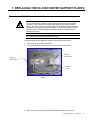
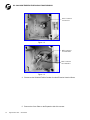
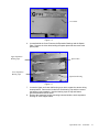
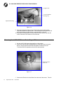
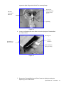
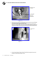
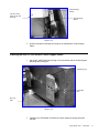
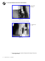
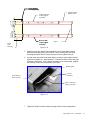
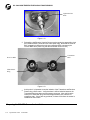
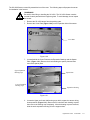
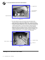
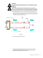
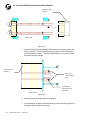
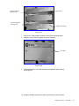
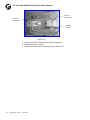
Fife Corporation P.O. Box 26508, Oklahoma City, OK 73126, U.S.A. Phone: 405.755.1600 / Fax: 405.755.8425 www.fife.com / E-mail: [email protected] SC-1000 High Temperature Capacitance Sensor Installation and Maintenance Manual Figure Sheet 1-803 04-28-2000 Copyright © 2000 Fife Corporation All rights reserved. Figure Sheet 1-803 04-28-2000 NOTICE This Operating Manual describes the replacement of the center plate of the SC-1000 sensor. It has priority over the general Operating Manual for the SC-1000. Copyright: All rights reserved. This custom Operating Manual may not be reproduced, by whatever means, in whole or in part, without the prior written consent of the FIFE Corporation. The information given in this custom Operating Manual may be subject to change without notice. We took the greatest care in compiling this Operating Manual; the possibility of error cannot be entirely excluded, however. The FIFE Corporation can accept no liability for incorrect information given, or the consequences arising therefrom. Copyright 1996 FIFE Corporation, P.O. Box 26508, Oklahoma City, OK 73126, U.S.A. FIFE GmbH, Postfach 1240, D 65779 Kelkheim/Ts., Germany Figure Sheet 1-803 04-28-2000 SC-1000 HIGH TEMPERATURE CAPACITANCE SENSOR Figure Sheet 1-803 04-28-2000 REPLACING THE SC-1000 CENTER SUPPORT PLATES 1 Removing the SC-1000 Sensor from the Furnace:..................................................1-1 Removing the old SC-1000 Sensor Center Support Plates .....................................1-4 Installing the new SC-1000 Sensor Center Support Plates:..........................................1-7 Preparing the SC-1000 Sensor for Installation .............................................................1-11 Installing the SC-1000 Sensor in the Furnace ..............................................................1-13 Figure Sheet 1-803 04-28-2000 i SC-1000 HIGH TEMPERATURE CAPACITANCE SENSOR Figure Sheet 1-803 04-28-2000 1 REPLACING THE SC-1000 CENTER SUPPORT PLATES: Removing the SC-1000 Sensor from the Furnace: WARNING The SC-1000 Sensor contains several Ceramic parts that serve as electrical insulators. Do not handle the Ceramic parts without using cotton protective gloves. Any Oil or Dirt on the Ceramic parts can cause the electrical isolation to breakdown in the extreme heat of the furnace. If the Ceramic parts have been contaminated, use standard Rubbing Alcohol to clean the insulators before installing the sensor. NOTE All dimensions and fastening hardware are metric. The following steps will prepare the sensor for removal from the furnace. 1. Turn off power to the SC-1000 Sensor. 2. Locate the electrical junction boxes on the Fixed side of the sensor. Electrical Junction Box Electrical Junction Box Shielded Conduit Figure 1.1 3. Open each Electrical Junction Box and disconnect the BNC connectors. Figure Sheet 1-803 04-28-2000 1-1 SC-1000 HIGH TEMPERATURE CAPACITANCE SENSOR BNC Connector for Receiver Figure 1.2 BNC Connector for Transmitter BNC Connector for Transmitter Figure 1.3 4. Disconnect the Shielded Flexible Conduit from both Electrical Junction Boxes. 5. Remove the Cover Plate on the Expansion side of the sensor. 1-2 Figure Sheet 1-803 04-28-2000 Cover Plate Figure 1.4 6. Located behind the Cover Plate are the Expansion Bearings and the Spacer Plate. Remove the 4 hex bolts holding the spacer plate and then remove the spacer plate. Upper Expansion Bearing Cups Spacer Plate Lower Expansion Bearing Cups Expansion Housing Figure 1.5 7. Locate the Upper and Lower ball bearing cups which support the sensor during heat expansion. Remove the 3 bolts from each bearing cup and then remove the bearing cups completely. Note the bearing cups are top and bottom specific and should not be mixed. 8. Remove the expansion housing mounting bolts and slide the entire expansion housing off of the support tubes. Figure Sheet 1-803 04-28-2000 1-3 SC-1000 HIGH TEMPERATURE CAPACITANCE SENSOR Support Tube Lower Expansion Bearing Cup Expansion Housing Figure 1.6 9. After the expansion housing is removed from the sensor support tubes, temporarily replace the spacer plate. This will keep the two support tubes at the proper spacing until the sensor is removed from the furnace. 10. Remove the mounting bolts from the Fixed side of the sensor and slide the entire Fixed side of the sensor out of the furnace. Removing the old SC-1000 Sensor Center Support Plates: 1. Set the old SC-1000 sensor horizontally on a flat surface. 2. Remove the all three BNC Receptacles from inside the Electrical Junction Boxes. Note that the Receiver BNC Receptacle is different from the Transmitter BNC Receptacles and should be kept separate. BNC Receptacle Removed Figure 1.7 3. Remove the Electrical Junction Boxes from the end of the sensor. This will 1-4 Figure Sheet 1-803 04-28-2000 expose the Spark Plug and the Shield Tube mounting flange. Shield Tube Mounting Flange and Hex Head Screws Electrical Junction Box Removed Spark Plug Figure 1.8 4. Loosen the Retaining Nut on the Plate Connection Spring and Threaded Rod on all three Plates. Retaining Nut Ceramic Insulators Transmitter or Receiver Plate Plate Connection Spring Assembly Figure 1.9 5. Remove the Threaded Rod from the Plate Connection Spring by twisting the Spark Plug in the CCW direction. Figure Sheet 1-803 04-28-2000 1-5 SC-1000 HIGH TEMPERATURE CAPACITANCE SENSOR Shield Tube and Hex Bolts Twist the Spark Plug CCW to remove the Threaded Rod Figure 1.10 6. Remove the Hex bolts from the Shielded Tube and remove the entire Shielded Tube with the Spark Plug and Threaded Rod. 7. Each of the Center Support Plates has two M10 bolts which hold the center plates onto a slotted flange at the end of the each plate assembly. Remove the Fixed Side Housing by removing the M10 bolts from the Center Support Plate. M10 bolt and Nut Figure 1.11 8. Lift the Center Support Plates off of the Fixed Side Housing and remove the Expansion Side Housing Support Tubes. 1-6 Figure Sheet 1-803 04-28-2000 Slotted Flange Mount Lift this Center Plate off the side housings Slotted Flange Mount Figure 1.12 9. Now the Expansion Housings are ready for the replacement Center Support Plates. Installing the new SC-1000 Sensor Center Support Plates: 1. Set the SC-1000 Fixed Side Housing on a level surface with the Center Support Mounting tabs pointing up. Mounting Tab Transmitter Side Receiver Side Figure 1.13 2. Install the new Transmitter and Receiver Center Support mounting slots onto the tabs. Figure Sheet 1-803 04-28-2000 1-7 SC-1000 HIGH TEMPERATURE CAPACITANCE SENSOR Slotted Flange Mounting Figure 1.14 3. Install the M10 Bolt and Nut to secure the assembly. M10 Bolt and Nut Figure 1.15 4. Perform the same steps to attach the Expansion Side Support Tubes to the Center Support Plates. 1-8 Figure Sheet 1-803 04-28-2000 Center Support Mounting Flange Expansion Side Support Tube Transmitter Side Center Support Assembly Fixed Side Housing Receiver Side Center Support Assembly Spacer Figure 1.16 5. Install the three new Shield Tube assemblies into the Fixed Side Housing. Slide each assembly back into the sensor. Start threading the Hex head mounting bolts back into the Fixed Housing but do not tighten them yet. 6. At each of the three Plate Connection Spring, reconnect the threaded rod and tighten the retaining nut. Approximately ¼” of thread should be inside the Plate Connection Spring Nut. If the Ceramic insulators are be compressed, readjust the retaining nut until the compression is removed. Retaining Nut Ceramic Insulators Transmitter or Receiver Plate Plate Connection Spring Assembly Figure 1.17 7. Tighten the Shield Tube Hex Head mounting bolts for all three assemblies. Figure Sheet 1-803 04-28-2000 1-9 SC-1000 HIGH TEMPERATURE CAPACITANCE SENSOR Tighten the Hex Bolts Figure 1.18 8. Reinstall the old Electrical Junction Boxes over the spark plug assemblies. And then install the BNC Connectors onto each Spark Plug. Note that the receiver BNC receptacle is different than the two transmitter BNC connectors (the receiver BNC has a plastic ring that the transmitter does not have). Transmitter BNC Receiver BNC White Plastic Ring Figure 1-19 9. At this point it is important to test the isolation of the Transmitter and Receiver Plates using a Ohm meter. Verify that there is infinite isolation between the Transmitter/Receiver plates and the support structures. Also verify that the center pin of each BNC plug conducts at approximately zero ohms to it’s respective plate. If there are any problems, fix them now before the sensor is installed into the furnace. Preparing the SC-1000 Sensor for Installation 1-10 Figure Sheet 1-803 04-28-2000 The SC-1000 Sensor comes fully assembled out of the crate. The following steps will prepare the sensor for installation in the furnace. !!WARNING!! Be careful when lifting or handling the SC-1000. The SC-1000 Sensor contains several Ceramic parts which are fragile as glass! To avoid damage, do not impact the sensor. 1. Remove the SC-1000 sensor from the packing crate. 2. Remove the Cover Plate (Figure 1-20.) on the Expansion side of the sensor. Cover Plate Figure 1-20 3. Located behind the Cover Plate are the Expansion Bearings and the Spacer Plate. (Figure 1-21.) Remove the 4 bolts holding the spacer plate and then remove the spacer plate. Upper Expansion Bearing Cups Spacer Plate Lower Expansion Bearing Cups Expansion Housing Figure 1-21 4. Locate the Upper and Lower ball bearing cups which support the sensor during heat expansion. (Figure 1-22.) Remove the 3 bolts from each bearing cup and then remove the bearing cups completely. After the bearing cups are removed, slide the entire expansion housing off of the support tubes. Figure Sheet 1-803 04-28-2000 1-11 SC-1000 HIGH TEMPERATURE CAPACITANCE SENSOR Support Tube Lower Expansion Bearing Cup Expansion Housing Figure 1-22 5. After the expansion housing is removed from the sensor support tubes, temporarily replace the spacer plate. (Figure 1-21.) This will keep the two support tubes at the proper spacing until the sensor is mounted in the furnace. 6. Before beginning the installation of the sensor, verify that the sensor plates are completely electrically isolated from the sensor housing using a Multimeter set to read resistance (Ohms). To check the resistance, open both electrical junction boxes which are mounted on the Fixed Housing. (One shown in Figure 1-23.) Disconnect the BNC connectors. Probe the center pin and the connector casing with the Multimeter on all three connector receptacles. The resistance should be infinite. If it is not infinite, investigate the ceramics to determine where the short-circuit is located and repair the problem. Connector Casing BNC Connector Center Pin Figure 1-23 Installing the SC-1000 Sensor in the Furnace 1-12 Figure Sheet 1-803 04-28-2000 !!WARNING!! Be careful when lifting or handling the SC-1000. The SC-1000 Sensor contains several Ceramic parts which are fragile as glass! To avoid damage, do not impact the sensor. !!WARNING!! The SC-1000 Sensor contains several Ceramic parts that serve as electrical insulators. Do not handle the Ceramic parts without using cotton protective gloves. Any Oil or Dirt on the Ceramic parts can cause the electrical isolation to breakdown in the extreme heat of the furnace. If the Ceramic parts have been contaminated, use standard Rubbing Alcohol to clean the insulators before installing the sensor. 1. Lift the SC-1000 sensor into place and slide it into the furnace opening. Use a sealant around the mounting flange of the furnace opening and loosely bolt the Fixed Side Housing of the sensor in place. Spacer Plate Furnace Wall TOP VIEW Figure 1-24 2. Remove the Spacer Plate from sensor. 3. Install the Expansion Side Housing of the sensor in place. Use a sealant around the mounting flange of the furnace opening and loosely bolt the Expansion Side Housing of the sensor in place. Figure Sheet 1-803 04-28-2000 1-13 SC-1000 HIGH TEMPERATURE CAPACITANCE SENSOR Expansion Side Housing TOP VIEW Figure 1-25 4. Install the Upper and Lower Bearing Cups and do not completely tighten the bearing cup bolts. The ball bearings that are located in each slot should be pushed towards the sensor. This allows the bearings to move outward when the sensor begins to expand. Expansion Side Housing Upper and Lower Bearing Cups Position Ball Bearing towards the furnace SIDE VIEW Figure 1-26 5. Install the Spacer Plate and tighten it completely. 6. Finish tightening the Upper and Lower Bearing Cups so that they support the Expansion Side Support Tubes loosely. 1-14 Figure Sheet 1-803 04-28-2000 Upper Expansion Bearing Cups Spacer Plate Lower Expansion Bearing Cups Expansion Housing Figure 1-27 7. Press on the Teflon sealant around the Cover Plate mounting flange. 8. Install the Cover Plate and tighten the Cover Plate bolts. Cover Plate Figure 1-28 9. Finish tightening the Fixed Side Housing and Expansion Side Housing mounting bolts. 10. Install the Shielded Conduits into both of the Electrical Junction Boxes. Figure Sheet 1-803 04-28-2000 1-15 SC-1000 HIGH TEMPERATURE CAPACITANCE SENSOR Electrical Junction Box Electrical Junction Box Shielded Conduit Figure 1-29 11. Reconnect the BNC Connectors to the BNC Receptacles. 12. Restore Power to the Sensor. 13. Calibrate the SDE-30 circuit board using Figure Sheet 2-217. 1-16 Figure Sheet 1-803 04-28-2000