1
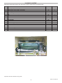
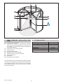
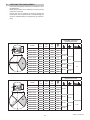
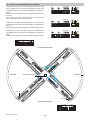
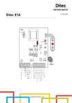
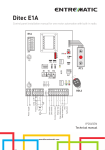
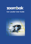
EXEO
IP1828GB - rev. 2006-01-18
GB
DITEC S.p.A.
Via Mons. Banfi, 3 - 21042 Caronno Pertusella (VA) - ITALY
Tel. +39 02 963911 - Fax +39 02 9650314
www.ditec.it - [email protected]
Installation and
maintenance
manual revolving doors.
GENERAL SAFETY PRECAUTIONS
MACHINERY DIRECTIVE
This installation manual is intended for professionally
competent personnel only.
Installation, electrical connections and adjustments must be
performed in accordance with Good Working Methods and in
compliance with applicable regulations.
Before installing the product, carefully read the instructions. Bad
installation could be hazardous.
The packaging materials (plastic, polystyrene, etc.) should not
be discarded in the environment or left within reach of children,
as these are a potential source of hazard.
Before installing the product, make sure it is in perfect condition.
Do not install the product in an explosive environment and atmosphere: gas or inflammable fumes are a serious hazard risk.
Before installing the motors, make all structural changes relating
to safety clearances and protection or segregation of all areas
where there is risk of being crushed, cut or dragged, and danger
areas in general.
Make sure the existing structure is up to standard in terms of
strength and stability.
The motor manufacturer is not responsible for failure to use
Good Working Methods in building the frames to be motorised
or for any deformation occurring during use.
The safety devices (photocells, safety edges, emergency stops,
etc.) must be installed taking into account: applicable laws and
directives, Good Working Methods, installation premises, system operating logic and the forces developed by the motorised
door or gate.
The safety devices must protect any areas where the risk exists
of being crushed, cut or gragged, or where there are any other
risks generated by the motorised door or gate. Apply hazard
area notices required by applicable regulations.
Each installation must clearly show the identification details of
the motorised door or gate.
Before making power connections, make sure the plate
details correspond to those of the power mains.
Fit an omnipolar disconnection switch with a contact opening
gap of at least 3 mm. Make sure an adequate residual current
circuit breaker and overcurrent cutout are fitted upstream of the
electrical system.
When necessary, connect the motorised door or gate to a reliable earth system made in accordance with applicable safety
regulations. During installation, maintenance and repair, interrupt
the power supply before opening the lid to access the electrical
parts.
To handle electronic parts, wear earthed antistatic conductive bracelets.
The motor manufacturer declines all responsibility in the event
of component parts being fitted that are not compatible with the
safe an correct operation.
For repairs or replacements of products only original spare parts
must be used.
The installer shall provide all information relating to automatic,
manual and emergency operation of the motorised door or gate,
and provide the user with operating instructions.
Pursuant to Machinery Directive (98/37/EC) the installer who
motorises a door or gate has the same obligations as the manufacturer of machinery and as such must:
- prepare the technical file which must contain the documents
indicated in Annex V of the Machinery Directive; (The technical file must be kept and placed at the disposal of competent
national authorities for at least ten years from the date of
manufacture of the motorised door);
- draft the EC declaration of conformity in accordance with
Annex II-A of the Machinery Directive and deliver it to the
customer;
- affix the CE marking on the power operated door in accordance with point 1.7.3 of Annex I of the Machinery Directive.
For more information consult the “Technical Manual Guidelines”
available on Internet at the following address: www.ditec.it
APPLICATIONS
Service life: 5 (minimum 5 years of working life with 600 cycles
a day)
Applications: HEAVY DUTY (For vehicle or pedestrian accesses to institutional complexes with very intense use).
- Performance characteristics are to be understood as referring to the recommended weight (approx. 2/3 of maximum
permissible weight). A reduction in performance is to be expected when the access is made to operate at the maximum
permissible weight.
- Service class, running times, and the number of consecutive cycles are to be taken as merely indicative having been
statistically determined under average operating conditions,
and are therefore not necessarily applicable to specific conditions of use. During given time spans product performance
characteristics will be such as not to require any special
maintenance.
- The actual performance characteristics of each automatic
access may be affected by independent variables such as
friction, balancing and environmental factors, all of which
may substantially alter the performance characteristics of the
automatic access or curtail its working life or parts thereof
(including the automatic devices themselves). When setting
up, specific local conditions must be duly borne in mind and
the installation adapted accordingly for ensuring maximum
durability and trouble-free operation.
DECLARATION BY THE MANUFACTURER
(Directive 98/37/EC, Annex II, sub A)
Manufacturer:
DITEC S.p.A.
Address:
via Mons. Banfi, 3
21042 Caronno P.lla (VA) - ITALY
Herewith declares that the electromechanical automatic system
for revolving doors series EXEO
- is in conformity with the provisions of the following other EC
directives:
Machinery directive 98/37/CE;
Electromagnetic Compatibility Directive 89/336/CEE;
Low Voltage Directive 73/23/CEE.
Caronno Pertusella, 20-02-2002
EXEO - IP1828-GB
2
Fermo Bressanini
(Chairman)
PACKAGE CONTENT
After having opened the wooden case, take out the various components in the following order:
REF.
20
11
14
16
18
1
15
22
B
C
12
19
21
DESCRIPTION
Transom (complete with radar)
Template
Geared motor unit or traction unit supports
Cover supports
Moveable wing reinforcement rods
Kinematic motion assembly
Pilar
Pilar extensions
PACKAGE 1
Fixed wing pins
Pins with angle
Pilar Base
PACKAGE 2 (optional)
Support lights
Supports
Fixed curved wing
Moveable wing
Automation cover
M.U.
pz.
pz.
pz.
pz.
pz.
pz.
pz.
pz.
Q.TY
2
1
2
2
3/4
1
1
4
pz.
pz.
pz.
4
4
1
pz.
3/4
pz.
pz.
pz.
pz.
3/4
4
3/4
2
Ante fisse
1
15
19
Important: store the material in a dry place.
3
EXEO - IP1828-GB
1
2
3
3x1,5 mm²
7
4
5
8
6
9
10
1.
EXEO STANDARD INSTALLATION FEATURES
2.
Power supply
Absorption
Max capacity
Accessories power supply
Maximum tip speed
Intermittence
Degree of protection
Temperature
[1]
[2]
Kinematic motion assembly
Connect power supply to a type-approved omnipolar
switch with a contact opening gap of no less that 3 mm
(not supplied by us) protected against accidental and
unauthorized activation
[3] Kinematic motion assembly supports
[4] Function selector
[5] Opening radar (optional)
[6] Disabled persons switch (optional)
[7] Protection sensor on the door (optional)
[8] Anti-shearing sensor
[9] Rubber strip
[10] Anti-trailing sensor (optional)
No special foundation works are required as the EXEO automatic
revolving door is designed to be positioned and mounted directly
on the finished pavement. Note: The floor must be absolutely
level (admitted tolerance ± 2 mm) and grit-free so as to ensure
smooth door operation.
EXEO - IP1828-GB
TECHNICAL DATA
4
230 V~ / 50-60 Hz
1A
1100 kg
24 V= / 0,3 A
1 m/s
S3=100%
IP20
-20° C / +55° C
3.
CHECKING THE PASSAGEWAY
-
Check that passageway dimensions correspond to door
measurements.
Make sure that there are no obstacles such as to prevent
proper door mounting.
Ensure that lean-on surfaces are smooth, regular and
perfectly flat, and if required raise to adequate height by
means of suitable shims (not supplied by the manufacturer).
-
PASSING CAPACITY
(people per minut)
HT
PH
PL
LM
S
LT
CODE
LT
mm
LM
mm
PL
mm
S
m²
EXEO 3A18
1800
800
720
0,7
EXEO 3A20
2000
900
820
0,9
EXEO 3A22
2200
1000
920
1,1
EXEO 3A24
2400
1100
1020
1,3
EXEO 3A26
2600
1200
1120
1,6
EXEO 3A28
2800
1300
1220
1,9
EXEO 3A30
3000
1400
1320
2,1
EXEO 3A32
3200
1500
1420
2,5
EXEO 3A34
3400
1600
1520
2,9
EXEO 3A36
3600
1700
1620
3,2
EXEO 3A38
3800
1800
1720
3,6
EXEO 3A40
4000
1900
1820
3,9
5-10
-
10-20
20-25
25-35
35-50
5-10
10-20
3-5
20-30
PASSING CAPACITY
(people per minut)
CODE
LT
mm
LM
mm
PL
mm
S
m²
EXEO 4A22
2200
1000
1390
0,8
EXEO 4A24
2400
1100
1530
1,0
EXEO 4A26
2600
1200
1670
1,2
EXEO 4A28
2800
1300
1820
1,4
EXEO 4A30
3000
1400
1960
1,6
EXEO 4A32
3200
1500
2100
1,9
EXEO 4A34
3400
1600
2240
2,1
EXEO 4A36
3600
1700
2380
2,3
EXEO 4A38
3800
1800
2520
2,7
EXEO 4A40
4000
1900
2660
2,9
HT
PH
PL
LT
S
LM
-
5
10-20
-
20-35
10-20
35-50
20-35
5-10
50-65
EXEO - IP1828-GB
4.
-
-
-
-
FOUNDATION RING (optional)
-
Join the two halves of the foundation base [13] with the
curved plates [F] and fasten them by means of the screws
supplied (TPSEI M6x6).
Prearrange the recess on the floor and insert the foundation
base [13].
Fasten the template [G] by means of the supplied screws
(TE M8x25) so as to ensure a proper horizontal doorway
(PL) measure.
Secure (see A) and/or cement the foundation base onto the
floor only after the perimeter has been perfectly levelled off
(approx. 2 mm) with the central pins [P], by means of the
dowels supplied (see B).
Once the above operations have been carried out, make
sure the foundation base is stable, then remove the template
[G].
-
Make sure the foundation base is slightly raised (C) as
compared to the finished floor surface, so that the weight of
the automation is carried by the foundation base only.
(Page 7, fig. 3) Secure the base [12] into its appropriate
seat.
A
B
6 mm
30
20
20
40
40
± 2 mm
STEI
M8x20
C
TCEI M8x50
EPFM M8
TP
SE
TE M8x25
B
IM
6x1
6
PL
Vano passaggio orizzontale
Horizontal passageway
4 mm
A
B
G
F
A
B
P
A
13
A
B
F
G
PL
Vano passaggio orizzontale
Horizontal passageway
EXEO - IP1828-GB
3 mm
6
5.
INSTALLATION
5.1 Setting up
If the foundation ring is not used (see chapter 4), do the
following:
Depending on LT, cut the template rod to the appropriate
size (see example in fig. 1).
Position the template [11] in the middle of the passageway, drill a hole of Ø14, insert the dowels, and firmly fasten the template to the ground.
(Fig. 2-3) Mark the anchoring points on the floor with the
aid of the template rod, drill a Ø14 hole and insert the
dowels and the relative pins [B] and [C]. The [C] pins
complete with angle bar must be positioned at the points
delimiting the passageway.
Repeat the operation for all six positions.
Remove the template and secure the base [12] at the
centre of the passageway.
4xØ14
LT=2400
11
LT=1800
LT=4000
Fig. 1
C
C
8xØ14
B
B
B
B
C
C
Fig. 2
C
B
M8X60
M8X80
12
Fig. 3
7
EXEO - IP1828-GB
5.2 Mounting the fixed wings
-
-
(Fig. 1) Slide out the 100-mm rubber strip, loosen screw
[E] and take it out.
Fit the fixed wings on to the pins, lifting them up and putting
them into place with the aid of the suction cups.
Tighten down and fasten screw [E] and put the rubber strip
back on.
(Fig. 2) Secure the wings to each other at the top by means
of the M6x90 screws.
(Fig. 3) Slide the motor supports [14] in from the top and
snap them into place.
(Fig. 3) Fasten the kinematic motion assembly [1] on the
its supports [3].
(Fig. 3) Lift up the motor unit [1]-[3] and place it sideways
on top of the supports [14]. Attention: The motor unit weighs
about 40 kg and must therefore be handled and moved
-
-
-
-
with adequate means.
Fit the pillar [15] (complete with rotating plate and moveable wing support) into the base [12], taking care not to
damage the fixed wings.
(Fig. 4) Shift the motor unit [1]-[3] up over the pillar [15]
and align the three holes in the rotating plate with those
in the pillar [24].
(Figs. 4-5) Fasten the motor unit [1]-[3] to the motor support
[14] and pillar [15].
N.B.: Motor [1] must be turn toward automation interior
side (fig. 6).
(Fig. 5) Secure the fixed wing support brace [23] in place
with the screws provided.
(Fig. 4) Insert extensions [22] in pillar [15] in accordance
with the numbers specified, and firmly tighten the screws
M12 provided.
(Fig. 5) Fasten support [16] to the motor supports [14].
24
1
22
5
M12
E
2
3
4
15
Fig. 1
Fig. 2
Fig. 4
1
3
14
23
23
1
14
24
3
16
Fig. 5
Motore visto lato INTERNO
Motor INSIDE view
1
Fig. 3
Fig. 6
EXEO - IP1828-GB
8
5.3 Mounting the moveable wings
-
-
-
(Fig. 1) Push the two screws [M] at the top of the moveable
wing support until the pin [N] moves up.
(Fig. 2) Fit the first moveable wing on to pin [17] in the
pillar base.
Move the wing up next to the top pin [N] and snap into
place.
Screw and tighten the screws [M].
Repeat the operation for all the moveable wings in sequence.
(Fig. 3) Align the wings with the top moveable wing supports and fasten into place by means of the screws.
If the break-in system is installed, simply align and snap
the wing into place.
(Fig. 4) Fix the curved edges [18] and the rods [26] on the
furniture door wings.
N
M
15
17
Fig. 1
Fig. 2
26
18
Fig. 3
Fig. 4
9
EXEO - IP1828-GB
5.4 Drive unit closing with the undercover
-
-
-
Put the mobile door wings in the close position.
(Fig. 1) Fix the false ceiling supports [27] on the brackets
[28].
(Fig. 1) Fix the ceiling support rods [30] adjusting them
with the brackets and hook [29] (see detail).
Lay the ceiling sections [19] and fix them with the brackets
[31].
Loosen the screws of the brackets [28] and using the four
dowels (see detail) level the whole ceiling support structure.
(Fig. 2) Fix all the ceiling sections minus one (recommended on the inside side) to make it possible to inspect the
motor group and electronic panel.
(Fig. 3) Lay the cover [21].
21
26
30
28
31
16
14
29
27
28
26
29
Fig. 1
Fig. 3
19
Fig. 2
EXEO - IP1828-GB
10
6.
5.5 Fixing of transoms
(Fig. 1) Fix the transom [20], complete with opening radar, over
the passing space by means of the 4 fixing points.
Fully wire up before finally closing with the undercover.
Turn the wings by hand and check that the movement is regular.
Fix the wirings by means of appropriate clamps to prevent them
from getting caught when the wings move.
MOUNTING THE OUTDOOR RAIN PROTECTION HOOD (optional)
Position the rain protection hood above the existing cover on
the outside of the door and secure it in place by means of selfthreading screws (not provided), making sure to seal off screw
heads with silicone.
20
11
EXEO - IP1828-GB
7.
EC - NIGHT CLOSING WINGS (Optional)
E
Slide guide for
left outside
night wing
Slide guide for
right outside
night wing
Right wing
Left wing
B
Fig. 1
HOW TO INSTALL
7.1
(Figure 1) Secure the slide guide for the left outside night
wing in place at the three securing points.
7.2
(Figure 2) Loosen and remove each of the closing stop
screws [A] on the two guides.
7.3
Fit into place the left outside night wing in the fully open
position and then proceed with the right outside night
wing.
7.4
(Figure 1) Secure the slide guide for the right outside
night wing in place at the three securing points.
Note: (Figure 1) Fully open the right outside night wing
to tighten centre screw [B] down into place.
7.5
(Figure 2) Refit the closing stop screws [A].
A
Fig. 2
EXEO - IP1828-GB
12
7.6
(Fig. 3) (Figure 3) Fully close the outside night-closing
wings. Take off the top part of the outside night wings.
C
Fig. 3
-
7.7
7.8
(Fig. 4) (Figure 4) Adjust wing height proceeding as follows:
loosen screw M8 located on the inner side of the carriage;
act appropriately on screw [E] located above the carriage,
tightening to raise and loosening to lower.
(Figure 3) Replace the top part of the outside night
wings.
After adjustment check for proper, friction-free wing gliding
and unhampered key locking.
To conceal screws apply the strips to the concave side of
the carriage guide by means of the double-face adhesive
tape.
M8
E
Fig. 4
In the event of a LOW ENERGY push-button being installed, secure support as shown in Figures 5 and 6.
Fig. 5
Fig. 6
13
EXEO - IP1828-GB
LM
LC
9E
6C
6B
6A
HB
HA
3B
3A
1
0
1
G1
G2
EL
29
MP
9
B
A
PG
1
1
XA
XB
SIDE A
6A
POWER
ALARM
SIDE B
6A
ON
10 9
RN
VM
10 9
RR
VP
VR
PS
R1
2122
RF
COM
Sezione personalizzazione
Personalization area
MOBILE
9E
9E
FC2
FC1
Sezione protetta
Protected area
ON
1 2 3 4 5 6
J26
EF
BC D
6B 6C 9E
32
0 12
10 9
BAT
-LD+
-BK+
TD TS
TR
FP
Sezione installazione
Installation area
TA
1 2 3 4
E
N
C
DON’T
USE
ELOK2
WARNING INSTALLATION ONLY
NS
ON
DEFAULT
-MOT+
Motor
24 V=
+ Battery 12V 2 Ah -
32
Disabilitazione momentanea
delle sicurezze
Momentary safety disable
87
654
ComK Selector
32
- Battery 12V 2 Ah +
R58
8 9A
F10A
R57
34 5
67
87
654
14
87
654
EXEO - IP1828-GB
F1
DOOR LIGHTS
230V
POWER
POWER
L N
Transformer
230 V~
50 Hz
8.
ELECTRICAL CONNECTIONS
8.1 Commands
Command
Function / Value
1
0
+
-
1
3A
N.O.
1
3B
N.O.
1
HA
N.O.
1
HB
N.O.
1
6A
N.C.
1
6B
N.C.
1
6C
N.C.
1
9E
N.C.
1
LC
N.O.
1
LM
N.O.
24 V= / 0.3 A
Description
Accessory power. External accessory power outlet.
INTERNAL SIDE OPENING
It activates the side A opening manoeuvre. The door carries out at
normal speed (trimmer VM) a number of revolutions set by trimmer
RN.
EXTERNAL SIDE OPENING It activates the side B opening manoeuvre. The door carries out at
normal speed (trimmer VM) a number of revolutions set by trimmer
RN.
INSIDE SIDE HANDICAP
It activates the side A opening manoeuvre in Low Energy mode. The
OPENING
door carries out at reduced speed (trimmer VR) a number of revolutions
set by trimmer RR.
EXTERNAL SIDE HANDICAP It activates the side B opening manoeuvre in Low Energy mode. The
OPENING
door carries out at reduced speed (trimmer VR) a number of revolutions
set by trimmer RR.
ANTI-CUTTING STOP
It stops the movement of the door. Once the contact is restored, and
anyway for a minimum time of 1 sec., the door completes the interrupted
manoeuvre.
ANTI-TRAIL STOP
It stops the movement of the door. When the contact is restored, the
door stays still for a time set by trimmer TS. Later the door starts moving
again at reduced speed (trimmer VR) for a time equal to TS, completing
the interrupted manoeuvre.
FURNITURE DOOR SLOW
With DIP2=OFF (Installation section), the speed of the door wing is
DOWN/STOP SENSOR
reduced (trimmer VR) during the opening of the 1-6C contact.
With DIP2=ON the behaviour of contact 1-6C is the same as that of
contact 1-6B.
EMERGENCY STOP
The opening of contact 1-9E stops any movement in progress, it blocks
the implementation of every voluntary command, it activates the door
block if released and suspends the Door and Wind Resistance Device
maintenance.
Once contact 1-9E has been restored, the emergency stop function
remains active until an opening or handicap opening command is
given, if DIP4=OFF (protected section); or after a standby interval of 1
sec if DIP4=ON (protected section).
LIGHT ENABLING
The lights are always off when the contact is open.
With the contact closed, the lights come on in the way provided for by
contact 1-LM.
LIGHT MODE SELECTION
With the open contact the lights come on only during the manoeuvre
Note: the lights do not go out if a safety stop device cuts in.
The lights are always on when the contact is closed.
ON
OFF
YELLOW LED
Indicates the activation of the command Indicates the command is deactivated (N.O.)
(N.C.).
RED LED
Indicates the safety device has cut in (N.O.).
Indicates the safety devices are normally
working (N.C.)
Important: make a jumper between all the N.C. contacts if not used. The clamps with the same number are equivalent. The given
operating and performance features can only be guaranteed with the use of DITEC accessories and safety devices.
15
EXEO - IP1828-GB
8.2 Function selector
Command
Function
1
PG
N.O.
1
A
1
B
1
Description
PUSH AND GO ENABLING
The closure of the contact causes the permanent activation of the door
block and enables push opening.
N.O.
SIDE A ENABLING
The closure of contact 1-A enables opening commands 3A and HA.
N.O.
SIDE B ENABLING
The closure of contact 1-B enables opening commands 3B and HB.
9
N.C.
CLOSED DOOR STOP
The opening of contact 1-9 interrupts any manoeuvre in progress, the
door is positioned with reduced speed (VR) next to the FC1 limit switch
ignoring every other command, safety devices excepted.
1
MP
N.O.
PERMANENT MOVEMENT
ENABLED
The closure of contact 1-MP starts the permanent rotation of the door
at the speed set through trimmer VP.
1
29
N.O.
RESET
Annuls all the captured data.
1
EL
N.O.
DOOR BLOCK EXCLUSION
The closure of contact 1-EL maintains the door blocking device in the
door unblocked conditions throughout the command.
ON
OFF
YELLOW LED
Indicates the functioning mode is activated Indicates the functioning mode is deactivated
(N.C.).
(N.O.).
RED LED
Indicates the night closure mode is activated Indicates the night closure mode is deactivated
(N.O.).
(N.C.).
RESET
RESET
EXEO - IP1828-GB
16
Functioning mode
Two-direction automatic device: the door is
normally closed. Following an opening command,
the door turns at normal manoeuvring speed
(VM) for a number of revolutions set by the RN
until it returns to its initial position.
Single-direction automatic device: the door is
normally closed. Following a side A command,
the door turns at normal manoeuvring speed
(VM) for a number of revolutions set by the RN
until it returns to its initial position.
Permanent Rotation: the door is always in
rotating mode at the permanent speed (VP). An
opening command switches it to normal speed
(VM) for the number of revolutions set (RN), then
to return to the permanent speed.
Push and Go: the door begins the movement
following a manual push of the door wing for the
number of sectors set by trimmer NS.
Door blocked: the door is closed and locked by
the electromechanical lock. Following a voluntary
external command (e.g. the night porter) it will
perform the number of revolutions set by RN,
at normal speed, then it will stop in the locked
position.
Night closure (STOP): the door is stopped
closed and does not accept commands.
Annuls all the data acquired from the electronic
panel
8.3 Outputs/Inputs
1
Output
G1
Value
24 V=/0.1 A
1
G2
24 V=/0.1 A
1
XA
1
XB
Description
Output 1-G1 can be connected to a visual and/or acoustic device as an alarm
if one of the following fault conditions:
- no mains electricity;
- no batteries or short-circuited;
- dead batteries (a check is made on start up and every four hours).
It is possible to reset the alarm condition through the ECOMK functions
selector.
Note: if the battery is dead, wait for around thirty minutes to allow the battery
to recharge if possible.
General Purpose. FUTURE USE.
Side A anti-intrusion command. Connect the foot plate that reveals the
presence of a person in the direction that is not permitted.
Side B anti-intrusion command. Connect the foot plate that reveals the
presence of a person in the direction that is not permitted.
Encoder-motor connection. Connect the motor and the encoder to the
electronic panel by means of the cables supplied (as indicated in figure X).
It is possible to connect one or two emergency stop devices.
Note: Open the relative jumper.
- MOT +
ENCODER
9E
9E
It allows the connection of the optical limit switch to the connector [PS].
Note: the FC2 limit switch led remains on at all times. the FC1 limit switch led
turns on when the door is in the closed position.
FC2
FC1
PS
FUTURE USE.
COM
21
22
FUTURE USE.
FUTURE USE.
BAT
2 x 12 V / 2 Ah
-LD+
24 V= / 1.2 A max
NOT USED
-BK+
POWER
230 V~
DOOR LIGHTS
The batteries guarantee non-stop functioning even when there is no mains
electricity. To charges the batteries, connect them to the mains at least thirty
minutes before starting up the system. To remove power to the electronic panel
you must remove the power supply and disconnect the batteries.
Important: to allow recharging, the batteries must always be connected to the
control panel. Check the efficiency of the battery kit periodically.
Electronic lock. Outlet for the electrolock ELOK2 power supply.
230 V~ / 100 W max
Power supply connection. Connect the power supply assembly to the
electronic panel by means of the cables supplied (as indicated in figure X).
Spotlight connection. Connect the lights inside the door to the electronic
panel by means of the cables supplied (as indicated in figure X).
17
EXEO - IP1828-GB
8.4. Safety and command device connections
6B 6C 9E
This allows the connections of the protection sensors on the
door wing [AA] and the anti-trail devices [AB] by means of the
rotating contacts up to the connector [MOBILE] on the electronic
panel.
Buttons 6B and 9E when pressed override the relative safety
contacts.
Note: Safety contact 6B on the furniture door wing is not used
and is overridden by the relative dip-switch.
6A
SIDE A
SIDE B
MOBILE
FC2
FC1
PS
6B 6C 9E
6A
6A
9E
FC2
FC1
9E
SIDE A
SIDE B
MOBILE
PS
6B 6C 9E
It allows the connection of the anti-cutting sensor, opening radar
and disable button to the connector [SIDE B] of the electronic
panel.
Button 6A when pressed, overrides the relative safety contact.
SAFETY
9E
9E
It allows the connection of the anti-cutting sensor, opening radar
and disabled button to the connector [SIDE A] of the electronic
panel.
Button 6A when pressed, overrides the relative safety contact.
DISABLE
6A
6A
6A
6A
9E
FC2
FC1
9E
SIDE A
SIDE B
MOBILE
PS
OPEN
0 1 6A
0 1
H
3
OUTSIDE TRANSOM (SIDE B)
.3
N
1
0
DI
6C SAB
|9E LE
|6B
T
T
ED
|O GE
U
IN
OU
AB
AA
IN
IN
IN
GE T
ED |OU
IN
OU
T
TE
IA
ED
RM
TE
I
W
IN
TE
NG
RM
E
1
DI
AT
E
2
W
3
IN
G
E
BL B
SA |6
DI |9E
6C
1
2
3
0
1
6C
6C
9E
9E
6B
6B
W
.2
N
IN
G
G
IN
W
OUTSIDE DOORWAY (SIDE B)
AB
AA
AB
FIXED WING
FIXED WING
AB
ROTATING CONTACTS
AA
AB
AA
IN
G
ED
IN
|
OU
T
E
OU
T
DI
SA
6B BLE
5
GE
4
ED
3
T
1
RS
6B
FI
GE T
EDIN|OU UT
O
IN
1
2
6
IN
W
0
G
E
BL B
SA |6
DI |9E
6C
LA
ST
W
1
2
0
3
0
1
1
DI
6C SAB
|9E LE
|6B
G
IN
3
6C
6C
9E
9E
6B
6B
W
+L
+L
W
-
G
IN
W
W
.4
N
IN
G
DON’T USE
N
.1
1
2
DON’T USE
INSIDE DOORWAY (SIDE A)
DISABLE
6A
SAFETY
0 1 6A
OPEN
0 1
3
INSIDE TRANSOM (SIDE A)
EXEO - IP1828-GB
18
H
9.
PERSONALISATION SECTION
RN
Normal speed revolutions.
0 - 1 = 1 revolution (*)
2 = 2 revolutions
3 = 3 revolutions
4 = 4 revolutions
5 - 6 - 7 - 8 -9 = 5 revolutions
RR
Reduced speed revolutions.
0 - 1 = 1 revolution (*)
2 = 2 revolutions
3 = 3 revolutions
4 = 4 revolutions
5 - 6 - 7 - 8 -9 = 5 revolutions
VM
Normal revolving. Adjustment of the peripheral speed (min = 400 mm/s - max = 1000 mm/s).
VP
Permanent revolving. Adjustment of the peripheral speed (min = 200 mm/s - max = 400 mm/s).
VR
Reduced revolving. Adjustment of the peripheral speed (min = 50 mm/s - max = 200 mm/s).
R1
Pushing on the obstacles. The electronic panel is fitted with a safety device that stops movement if an obstacle is
encountered. When the obstacle is removed, the door stays still for a time set by trimmer TS. Later the door starts
moving again at reduced speed (trimmer VR) for a time equal to TS, completing the interrupted manoeuvre.
With R1=MIN there is maximum sensibility to obstacles (minimum thrust).
With R1=MAX there is minimum sensibility to obstacles (maximum thrust).
RF
Power adjustment. This regulates the current supplied to the motor (min = 20% - max = 100%).
OFF
DIP1
Wind
Resistance
Device.
Disabled (*)
ON
Enabled. It keeps the door still in wind.
ON
LED POWER ALARM
24 V= power supply on.
FLASHING
This indicates malfunctioning of the panel or a mistake in the
wiring.
(*) Factory settings.
19
EXEO - IP1828-GB
10. INSTALLATION SECTION
Important: the following adjustments must be made at the installation stage, only by skilled personnel.
NS
Sector number. This makes it possible to set the number of door revolving sections following a manual push (Push
and Go).
0 - 1 = 1 sector
2 = 2 sectors (*)
3 = 3 sectors
4 = 4 sectors
5 = 5 sectors
6 = 6 sectors
7 = 7 sectors
8 = 8 sectors
9 = 9 sectors
TA
Acceleration regulation. This determines the acceleration time at the start.
TD
Slowdown regulation. This determines the slowdown time at the arrival.
TS
Time still. This regulates the stop time of the door following a safety device cutting in or the detection of an
obstacle (min = 1 s - max = 5 s).
TR
Delayed start. After an opening command, this regulates the time of the delay with which the door begins to
revolve (min = 0 s - max = 5 s).
FP
Holding the position. This regulates the maximum current required for holding the door still
(min = 1 A - max = 2 A).
DEFAULT FUTURE USE
OFF
ON
DIP1
Type of electronic lock
ELOK2 (*)
FUTURE USE.
DIP2
Furniture door wing sensor mode.
Slow down. (*)
Stop.
DIP3
Anti-cutting device mode
For EXEO 4 door wing (active in the For EXEO 3 door wing (connection
last 10° of the opening compartment). with activation magnetic-read).
DIP4
Electronic lock working
Normal functioning.
(*) Factory settings.
EXEO - IP1828-GB
20
Earlier functioning than the door
movement.
Note: This guarantees the release
of the door even when friction is
present.
11. PROTECTED SECTION
Important: the following factory settings of the protected section must not be changed.
LT
Door size. This indicates the door size.
0 = 1800 mm
1 = 2000 mm
2 = 2200 mm
3 = 2400 mm
4 = 2600 mm
5 = 2800 mm
6 = 3000 mm
7 = 3200 mm
8 = 3400 mm
9 = 3600 mm
A = 3800 mm
B-C-D-E-F = 4000 mm
OFF
ON
DIP1
Furniture door wing number
4
DIP2
Functioning mode
Automatic (The door is moved by the Semiautomatic (The door is moved
motor *)
manually. At the end, the door moves
automatically at the end position)
DIP3
Turn-style functioning
Disabled (*)
DIP4
Method of restarting after an Restarting follows a command (from The door moves automatically into the
emergency stop or the collapse of radar or from button pad) (*)
closure position.
a door wing
DIP5
Running direction
Anti-clockwise revolving (*)
Clockwise revolving
DIP6
FUTURE USE.
/
/
3
Enabled. The door only moves the
sectors necessary for one person
to get through (Exeo3 = 1 sector;
Exeo4 = 2 sectors).
(*) Factory settings.
11.1 MOTOR REVERSIBILITY ADJUSTMENT
The cutting of the components listing below reduces the force necessary to push the door manually.
J26
R57
R58
Strong thrust force
Medium-strong thrust force
N.O.
Medium-low thrust force
N.O.
Low thrust force
N.O.
21
EXEO - IP1828-GB
12. SAFETY AND COMMAND DEVICES
14. MAINTENANCE PROGRAM (each 6 month)
To make any regulations of the command devices (opening
radar) and safety devices (anti-cutting sensors, protection
sensors on the furniture door wing, anti trail hip) refer to the
relative manuals supplied with the door.
MAINTENANCE OF THE METAL STRUCTURE
Disconnect 230 V~ power supply
Protection against corrosive agents
The automation is protected by a corrosion-proof paint, but it
can be exposed to the following factors:
Corrosion by atmospheric agents
- Atmospheric pollution (urban and industrial areas)
- Atmospheric salinity (seashore areas)
- Seasonal climate variations and humidity rate
Abrasive action
- Atmospheric dust and sand carried by the wind.
To preserve the metal structure it is necessary:
- to avoid dirt accumulation;
- to soften the surface to be cleaned with water before removing
dirt by rubbing;
- not to use solvents as they can damage the paint.
13. START
13.1 Check that all the N.C. contacts are correctly connected
or jumpers have been made as indicated in chapter 8.
13.2 Power up and check the correct working of the door with
later commands for opening (1-3A, 1-3B) and opening for
disabled people (1-HA, 1-HB) at reduced speed.
13.3 Check the proper functioning of the opening radar (if
necessary make the regulations shown in the relative
manual).
13.4 Check the proper functioning of the safety devices (if
necessary make the regulations shown in the relative
manual).
13.5 Connect any accessories and the function selector and
check the functioning.
13.6 If the automation encounters an obstacle during
movement.
13.7 Shut the door with the ceiling structures.
13.8 If necessary consult, the troubleshooting section in
chapter 15.
MAINTENANCE OF THE ELECTRONIC PARTS
Rotary contacts (ECR)
- Remove the protective cover between the fixed part and the
rotary disc and wipe away dust.
- Carry out some idle rotations and check everything functions
properly.
Connectors and safeties
- Check connections and continuity of contact, making sure
there are no interruptions in the wiring.
- Clean and check radars and anti-shearing sensors are properly
orientated.
- Check the correct mechanical and electronic functioning of
the ball contacts on the moving wing (if any).
- Check magnetic sensors activate where pre-arranged.
MAINTENANCE OF THE MECHANICAL PARTS
- Check gaskets and brushes are properly positioned.
- Make sure all screws are tightly fastened (especially those on
the moving wings).
- Make sure motor supports are properly positioned in the fixed
wings.
- Make sure, by manually rotating the automation, there are no
friction points.
- Replace the transmission belt each 2 years.
Connect 230 V~ power supply
- Check stability and smooth and trouble-free movement of the
door.
- Check all control and safety accessories are properly
functioning.
EXEO - IP1828-GB
22
15. TROUBLESHOOTING
PROBLEM
The door does not move
POSSIBLE CAUSE
REMEDY
No power supply (POWER ALARM LED Check that there is mains electricity.
off).
The safety contacts are open.
Make sure the connection is sound or that
all the safety devices have been safety
devices have been correctly overridden
(red leds 6A, 6B, 6C, 9E must be off).
The function selector is in the door closed Change the selected function.
position or in the night-time closure
position (red led 9 is on).
No opening commands are received.
Check that the radars are powered and
correctly functioning.
Check that the function selector is
correctly connected.
The door wings have collapsed
Lock the door wing in the correct
position.
The door does not stop
The opening radars are active (the leds Check the adjustments and the
orientation of the sensor. Remove any
3A, 3B are on)
moving objects.
The door starts and stops with jerky
movements
The protection sensors are on
The door works at reduced speed
The opening commands for disabled Check the functioning of opening
people are active (the leds HA, HB are commands for disabled people.
on)
23
Check the adjustments and the
orientation of the sensor. Remove any
objects that are present.
EXEO - IP1828-GB
OPERATING INSTRUCTION FOR REVOLVING DOOR EXEO
If there is no power, the automatic version of the EXEO door
continues to function by means of the batteries supplied.
If the absence of power continues for a long time on in the case
of failures do the following:
- remove mains power (fig. 1);
- if there is an electromechanical ELOK2 lock, release the
door wing (fig. 2);
- push the door wing by hand (fig. 3);
- if there is an EAST collapsing system, free the passage by
collapsing the door wing (fig. 4).
Fig. 1
Fig. 2
GENERAL SAFETY PRECAUTIONS
Fig. 3
Fig. 4
ON
OFF
Installer:
DITEC S.p.A.
Via Mons. Banfi, 3
21042 Caronno Pertusella (VA) - ITALY
Tel. +39 02 963911 - Fax +39 02 9650314
www.ditec.it - [email protected]
TEAR OFF AND DELIVER TO USER
The following precautions are an integral and essential part of
the product and must be supplied to the user.
Read them carefully as they contain important indications
for the safe installation, use and maintenace.
These instruction must be kept and forwarded to all possible
future user of the system.
This product must be used only for that which it has been expressely designed.
Any other use is to be considered improper and therefore dangerous.
The manufacturer cannot be held responsible for possible damage caused by improper, erroneous or unresonable use.
Avoid operating in the proximity of the hinges or moving mechanical parts.
Do not enter the field of action of the motorised door or gate
while in motion.
Do not obstruct the motion of the motorised door or gate as this
may cause a situation of danger.
Do not lean against or hang on to the barrier when it is moving.
Do not allow children to play or stay within the field of action of
the motorised door or gate.
Keep remote control or any other control devices out of the reach
of children, in order to avoid possible involuntary activation of the
motorised door or gate. In case of breack down or malfunctioning
of the product, disconnect from mains, do not attempt to repair
or intervene directly and contact only qualified personnel.
Failure to comply with the above may create a situation of
danger.
All cleaning, maintenance or repair work must be carried out by
qualified personnel.
In order to guarantee that the system works efficiently and
correctly it is indispensable to comply with the manufacturer’s
indications thus having the periodic maintenance of the motorised door or gate carried out by qualified personnel.
In particular regular checks are recommended in order to verify
that the safety devices are operating correctly. All installation,
maintenance and repair work must be documented and made
available to the user.
All right reserved
All data and specifications have been drawn up and checked with the greatest care. The manufacturer cannot however take any
responsibility for eventual errors, ommisions or incomplete data due to technical or illustrative purposes.
25
EXEO - IP1828-GB
DITEC S.p.A.
Via Mons. Banfi, 3
21042 Caronno P.lla (VA)
ITALY
Tel. +39 02 963911
Fax +39 02 9650314
www.ditec.it
[email protected]
Quarto d’Altino (VE)
Caronno Pertusella (VA)
DITEC BELGIUM
LOKEREN
Tel. +32 (0)9 356 00 51
Fax +32 (0)9 356 00 52
www.ditecbelgium.be
DITEC DEUTSCHLAND
OBERURSEL
Tel. +49 6171914150
Fax +49 61719141555
www.ditec-germany.de
Lokeren
Oberursel
DITEC FRANCE
PALAISEAU
Tel. +33 1 64532860
Fax +33 1 64532861
www.ditec.fr
DITEC SVIZZERA
BALERNA
Tel. +41 91 6463339
Fax +41 91 6466127
www.ditecswiss.ch
Palaiseau
DITEC AMERICA
ORLANDO - FLORIDA - U.S.A.
Tel. +1 407 8880699
Fax +1 407 8882237
www.ditecamerica.com
Orlando
Balerna