1
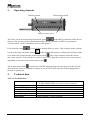
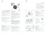
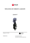
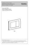
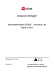
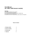
Installation and operating manual S-Box
Document number
Version
Copyright ©
1.
30322616-02-EN
20130116
Müller-Elektronik GmbH & Co. KG
Franz-Kleine-Straße 18
33154 Salzkotten
Germany
Phone: ++49 (0) 5258 / 9834 – 0
Fax: ++49 (0) 5258 / 9834 – 90
Email: [email protected]
Homepage: http://www.mueller-elektronik.de
Introduction
ISOBUS S-Box is section switching box with mechanical switches for the control of sections and the
main switch of the field sprayer ISOBUS. The switching box can be also operated in addition to the
ISOBUS multifunctional grip (MFG) or separately for the control of sprayer sections. Versions exist
with 2, 3, 4, 5, 6, 7, 8, 9, 10, 11, 12, 13 and 18 sections.
Sections:
Minimum software version of the ISOBUS job computer:
2-13
5.2xx
18
6.4i
2.
Mounting and cabling
If used together with a multifunctional grip, the S-Box can be mounted on the multifunctional grip.
The electrical connection of the S-Box is between the multifunctional grip and basic equipment. Pic.
2-1 shows the mounting and cabling with terminal, multifunctional grip and basic equipment.
If no multifunctional grip is used, the S-Box is connected between the terminal and basic equipment,
as shown in Pic. 2-2.
Basic
vehicle
harness
Pic. 2-1 Cabling with MFG
Copyright Müller-Elektronik GmbH u. Co. KG,
Basic vehicle
harness
Pic. 2-2 Cabling without MFG
Installation and Operating Manual S-Box (01/2013)
Page – 1
3.
Operating elements
Function switch
Section main switch
Section switch 1 to 13
The S-Box can be activated using the function switch
. In the MFG position the S-Box has no
function. The sections can be controlled depending on selected mode via MFG (see parameters
"section control" on the 3rd machine screen of the sprayer).
If the function switch
is set to S-Box, then the S-Box is active. This is shown on the working
. In this condition the sprayer evaluates the switch positions
screen of the sprayer with the symbol
set to S-Box for sections and the section main switch
. The section switches reflect the current
state of the sections. If the switch of a section is set to "ON", then the section is active or preselected
depending on the state of the section main switch
.
The section main switch
is used as the ON/OFF signal generator for the sprayer. In the ON state
all sections are active for which the switches are active. In the OFF state the sections engaged enter
the state as preselected.
4.
Technical data
Tab. 4-1: Technical data
Connections:
Power supply:
Power consumption:
Temperature range:
Housing:
Protection degree:
Dimensions:
Page – 2
1x 9pol. Sub-D plug (for terminal or MFG connection)
1x 9pol. Sub-D socket (for connection to basic equipment)
10.5 V – 16 V
Max. 0.7 A
-20 °C – 70 °C
Continuous alu casting with plastic end caps
IP 42
214mm x 40mm x 18 mm (WxHxD)
-
Copyright Müller-Elektronik GmbH u. Co. KG,
Installation and operating manual S-Box (01/2013)