1
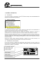
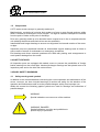
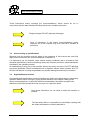
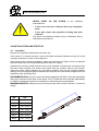
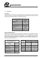
Scutti Deutschland GmbH
CTS SERIES TUBULAR SCREW CONVEYOR.
OPERATING MANUAL FOR
INSTALLATION, OPERATING AND MAINTENANCE
Spec. 5/96
KEEP THIS MANUAL FOR FUTURE CONSULTATIONS
Scutti Deutschland GmbH
Dear Client,
We thank you for choosing our CTS TUBULAR SCREW CONVEYOR.
We have prepared this manual to acquaint you better with the characteristics of our
machine.
You will find in the following pages useful operating advice and specific indications
regarding operatives’ safety.
We are sure that this manual will help you to use the machinery correctly, with
complete satisfaction and in total safety.
With best wishes for successful work.
SCUTTI DEUTSCHLAND GMBH
CTS Series screw conveyor - Operating and maintenance booklet - Page 2/15
Scutti Deutschland GmbH
SUMMARY
PAGE
1.0 GENERAL INFORMATION................................................................................................4
1.1
1.2
1.3
1.4
1.5
INTRODUCTION .............................................................................................................4
DETAILS OF COMPANY ..................................................................................................4
RECOMMENDATIONS FOR ASSISTANCE ..........................................................................4
IDENTIFICATION OF THE MACHINE ..................................................................................4
COMPOSITION ..............................................................................................................5
2.0 SAFETY DEVICES.............................................................................................................5
3.0 BASIC SAFETY WARNINGS ............................................................................................5
3.1
3.2
3.3
3.4
3.5
3.6
3.7
SAFETY WARNINGS AND SYMBOLS .................................................................................5
USE ACCORDING TO SPECIFICATIONS ............................................................................6
ORGANIZATIONAL PROVISIONS ......................................................................................6
SELECTION AND QUALIFICATION OF PERSONNEL ...........................................................7
SAFETY WARNING IN RELATION TO SCREW CONVEYOR OPERATION .................................7
ELECTRICAL POWER DANGER .......................................................................................7
CONDITIONS OF SAFETY AND PROTECTION.....................................................................7
4.0 INSTALLATION AND START-UP .....................................................................................8
4.1 INSTALLATION ...............................................................................................................8
4.2 START-UP ....................................................................................................................9
5.0 MAINTENANCE .................................................................................................................9
5.1 CLEANING ....................................................................................................................9
5.2 LUBRICATION ..............................................................................................................10
6.0 EPLACEMENT OF COMPONENTS ................................................................................11
6.1 STUFFING BOXES ........................................................................................................11
6.2 INTERMEDIATE SUPPORTS BEARINGS ...........................................................................12
7.0 DEMOLITION ...................................................................................................................13
8.0 DIFFICULTIES .................................................................................................................13
CTS Series screw conveyor - Operating and maintenance booklet - Page 3/15
Scutti Deutschland GmbH
1.0 GENERAL INFORMATION
1.1
Introduction
This manual contains a description of the CTS Tubular conveyor and recommendations for
operation and maintenance procedures
1.2
Details of company
Scutti Deutschland GmbH
Schönbrückstrasse 30
D-67376 Harthausen
Tel.: +49/6344-508-362
Fax: +49/6344-508-365
e-mail: [email protected]
Webside: www.scutti-deutschland.de
1.3
Recommendations for assistance
In compiling this instruction manual, careful attention has been paid to all considerations of
operation and maintenance during normal working conditions.
SCUTTI NICOLA recommend that you should not undertake operations, measures or
modifications to any component parts of the machine without written advice or consent.
Measures requiring replacement of parts or any operation other than ordinary maintenance
should be carried out exclusively by correctly qualified technical personnel who have the
necessary abilities as well as appropriate equipment to carry out the operations correctly,
safely and reliably.
Should you require further technical information or spares for your screw conveyor, it is
necessary to provide all data as indicated on the body of the machine.
1.4
Identification of the machine
Every screw conveyor is supplied with identification plates showing: the screw number, the
serial number, the assembly sequence number of each section, the year of manufacture and
the direction of rotation. For example:
The assembly sequence
of each section, if the
screw is made up of
several sections.
Screw number
SCUTTI NICOLA
Serial number
Year of manufacture
CTS Series screw conveyor - Operating and maintenance booklet - Page 4/15
Scutti Deutschland GmbH
1.5
Composition
A CTS series screw conveyor is generally made up of:
Machine body, consisting of a tubular body made up of one or more flanged sections, within
which is housed a screw flight or worm-on-pipe. The flight is rotated to transport the material
from the point of intake to the point of discharge.
Drive unit, generally made up of an electrical motor coupled to an in line to a speed reduction
unit (although belt drives and chain drives are also available).
Intermediate and hanger bearings to ensure true alignment and smooth rotation of the wormon-pipe.
Inspection ports are positioned beneath all intermediate support bearings and all inlets to
ensure ease of access for maintenance or emergency procedures.
End bearings and direct mounted gearboxes are fitted with packing seal arrangements to
avoid product leakage from the screw.
2.0 SAFETY DEVICES
All inspection ports are equipped with sealed covers to prevent the possibilities of foreign
bodies entering into the screw flight. Labels with danger warnings are also placed near to all
inspection ports and on the inlet and outlet orifices.
3.0 BASIC SAFETY WARNINGS
3.1
Safety warnings and symbols
In addition to the recommendations concerning the correct operation and maintenance of the
screw conveyor, we have included warnings of caution and safety for the attention of the
operation and maintenance staff as to the possible dangers arising from improper use.
Within this manual the following graphic symbols are used for warnings and indications of
possible danger:
WARNING
Special indications on correct use of the machine
WARNING, DANGER!
Special indication, provision and prohibition to
prevent injury to personnel
CTS Series screw conveyor - Operating and maintenance booklet - Page 5/15
Scutti Deutschland GmbH
These instructions and/or warnings are recommendations, which should be run in
conjunction with the latest Health and Safety directives in accident prevention.
Single warnings DO NOT eliminate the danger.
Lack of adherence to the safety recommendations and/or
improper use of the machine may incur the risk of accident to
personnel.
3.2
Use according to specifications
Whoever uses the machine must be aware of the existence of this manual and must fully
apply all the instructions and recommendations contained in it.
It is advised to use the machine under normal working conditions and in accordance with
standard specifications, whilst maintaining safety and accident prevention recommendations
contained in the operating manual.
All modifications to any part of the machine without the written consent of SCUTTI NICOLA
are strictly prohibited. Should modifications be undertaken without written consent, SCUTTI
NICOLA will decline to accept responsibility for possible damages caused by the machine.
3.3
Organizational provisions
All operating and maintenance personnel should study these instructions before commencing
operation with the screw conveyor, paying special attention to the chapter relating to the
safety recommendations. In particular these recommendations should be brought to the
attention of staff who operate the screw conveyor on a part time basis.
Keep these instructions for use close to where the machine is
located.
The site safety officer is responsible for periodically checking that
the safety standards are correctly adhered to.
CTS Series screw conveyor - Operating and maintenance booklet - Page 6/15
Scutti Deutschland GmbH
3.4
Selection and Qualification of Personnel
Establish the operative’s responsibility for the machine and authorise him to not undertake
any instructions from a third party that could contravene safety recommendations.
3.5
Safety warning in relation to screw conveyor operation
Constant awareness as to the dangers of operating a screw conveyor must be undertaken at
all times. Before commencing any operation, ensure you are concentrating your attention on
what you are about to do. Under no circumstances should you operate the screw conveyor if
you are under influence of alcohol or drugs.
Refrain from any operation that could compromise safety.
Ensure there is an adequate level of cleanliness within the machine and in its surrounding
area, as well as suitable safety lighting, for all personnel.
The indication, recommendation and danger signaling plates must be kept clean, maintained
in good condition and clearly mounted in the appropriate areas.
3.6
Electrical Power Danger
Only fully qualified electricians should attempt connection to a
power supply.
Before carrying out inspection, maintenance and repair procedures
check first that the power supply is disconnected before
commencing.
3.7
Conditions of safety and protection
All personnel should strictly adhere to the latest health and safety recommendations
IN PARTICULAR, maintain the following recommendations:
During all operation and maintenance procedures utilize all
personal protection equipment as instructed in the la test health
and safety recommendations and/or by the building
management.
Before carrying out inspection, maintenance and repair
procedures ensure the screw conveyor is securely positioned
and that its weight is fully supported.
Before proceeding with maintenance operations on the screw
conveyor, make sure that the supply voltage is disconnected.
CTS Series screw conveyor - Operating and maintenance booklet - Page 7/15
Scutti Deutschland GmbH
NEVER START
circumstances:
UP
THE
SCREW
in
the
following
− If the cover has been removed from any inspection
ports
− If the ratio motor unit protective housing has been
removed
The above circumstances should only be undertaken during
maintenance procedures.
4.0 INSTALLATION AND START-UP
4.1
Installation
Remove the protective packing from the drive unit.
If the screw is in several sections, remove the flight restriction brackets and lay the screw
conveyor sections out in the correct sequence.
After removing the protective packaging, make sure that the screw flight is free to rotate and
check that there are not foreign bodies present within the casing.
Assemble the various central sections of the screw together, ensuring that all sections have
the same serial numbers and check at the same time the numeric order of the sections.
Insert the paper gasket between the connecting sections and bolt the flanges together,
making sure of the exact alignment between the inlet with the outlet and the alignment of the
inspection ports and lifting eyes.
RECOMMENDATION: Once the screw has been assembled, lift ONLY using the appropriate
lifting eyes mounted to the back of the casing. SCUTTI NICOLA will not accept responsibility
or claims for damages caused by not adhering to these lifting recommendations.
MAXIMUM WEIGHTS relating to screw conveyors made from several sections. L= metres in
length:
ØD
KG.
Ø114
50+ (18xL)
Ø139
65+ (30xL)
Ø168
135+ (35xL)
Ø193
150+ (39xL)
Ø219
190+ (45xL)
Ø273
265+ (52xL)
Ø323
315+ (70xL)
CTS Series screw conveyor - Operating and maintenance booklet - Page 8/15
Scutti Deutschland GmbH
Locate the screw conveyor in the correct position and ensure that it is adequately supported.
For screw conveyors longer than 5 metres it is recommended that each 3m intermediate
section should be supported.
Ensure that inlets are correctly connected and sealed to restrict the possibilities of damage
from foreign bodies from entering the screw conveyor and accidents occurring. Ideally each
inlet should be fitted with a shut off valve.
4.2
Start-up
Before starting up the screw, make sure that no foreign bodies have entered during
assembly; if they have, remove them.
Ensure the intermediate and end support bearings are greased and that the drive oil is at the
correct level. Check that all the inspection ports are closed and sealed.
Make the electrical connection to the screw, adhering to the specifications indicated on the
motor plate, paying particular attention to the supply voltage.
IMPORTANT: All connections should be undertaken by qualified electrical personnel only.
Before carrying out any operation on the motor, make sure that the electrical supply is
disconnected. The constructor declines to take any responsibility for any damages to
property or persons, arising from poor electrical workmanship.
Once the connection has been completed, start up the machine empty, ensuring that the
direction rotation corresponds to the direction of the arrow as indicated on the identification
plate. If the direction of rotation is wrong, reconnect inverting the polarity of the motor.
Start up the screw again on empty and then gradually begin to introduce the product until
reaching the normal operating capacity.
If screw conveyor are assembled in succession, ensure that the feeding screw conveyor
throughput is lower than the throughput of the secondary screw conveyor. This allows the
secondary conveyor to discharge the product quicker than it is being fed and minimizes the
potential of product buildup.
5.0 MAINTENANCE
5.1
Cleaning
At the end of each working day, run the screw conveyor until empty. This operation will
prolong the life of the screw, especially in the presence of materials that have a tendency to
flood feed, forming build ups that could cause problems during start-up, particularly after log
periods of inactivity.
CTS Series screw conveyor - Operating and maintenance booklet - Page 9/15
Scutti Deutschland GmbH
5.2
Lubrication
SUPPORTS.
It is recommended to grease the end support bearing every 150 hours and the intermediate
support every 40 hours of operation. NEVER USE OIL FOR LUBRICATION. Below is a table
showing the type and brand name of recommended greases:
RECOMMENDED GREASES
TYPE
BRAND
PGX-SUPER
MOBILUX
API
MOBIL
BP-ENERGREASE L2
CALYPSOLH 433
BP
CALIPSOL
ANDOK B
ESSO
GR-MU
ARAL
GLISSANDO FL 20
TEXACO
REDUCTION GEAR UNITS.
After the first 500 hours of operation, replace the oil completely. Then, periodically check the
lubricant level and change the oil every 3000 hours of work. If synthetic oil is used, the
change may be made every 6000 hours of operation. If it is anticipated that the reduction
gear unit should remain inactive for a long period of time in a humid environment, it is
advised to fill completely with oil. Below is a table of the oils recommended, equivalent to the
respective operational conditions:
GEARBOX CAPACITY/ANGLE OF SCREW
TYPE
Litres
Litres
RECOMMENDED OILS
BRAND
RM series
0°≤ α ≤15°
16°< α ≤45°
API
RM 400
1,2
1,4
OMALA 220
SHELL
RM 500
1,5
1,8
TIVELA OIL WA
SHELL
RM 1000
1,9
2,4
PONTIAX HD
IP
RM 2000
2,0
2,8
ENERGOL SG 150
BP
RM 3000
3,5
4,9
TYPE
DT-220
MOBILGEAR 629
MOBIL
CTS Series screw conveyor - Operating and maintenance booklet - Page 10/15
Scutti Deutschland GmbH
6.0 REPLACEMENT OF COMPONENTS
All SCUTTI NICOLA screw components are manufactured for long life operation; however
some components due to the nature of their position and duties are subject to high levels of
wear and tear, and therefore need to be replaced periodically.
6.1
Stuffing boxes
Mounted to the RM direct reduction gear units and the end support bearings are stuffing
boxes which house felt seal packing arrangements. These units are under constant contact
with the product and should be replaced approximately every 2 years, ( if used with a non
abrasive product). When conveying an abrasive product the stuffing boxes are subjected to a
higher wear and tear and will therefore require replacing on a more regular basis. The gear
units and end support bearing are all designed to allow product leakage once the stuffing box
needs replacing without allowing the product to enter their internal workings. Any product
leakage should be reported to a member of the maintenance staff who should replace the
stuffing box immediately. Below is described stuffing box’s replacement procedure:
1) Ensure that no product can feed the screw, by closing the valve on the silo.
2) Run the screw until empty.
3) Disconnect voltage supply, by removing wires on motor’s terminal board.
4) Open the inspection port located beneath the inlet.
5) Insert a wooden plank (C) into the port and fix it so that the flight cannot slide
backwards.
6) Take out the drive unit (A) by removing the fixing screws.
7) Remove the stuffing box (B) and replace it with a new one.
8) Re-assemble the components by following the procedure backwards.
The above procedure is also to be followed when you must replace the stuffing box on the
end bearing (E) or when the drive unit is mounted at the outlet.
E
D
A
C
B
CTS Series screw conveyor - Operating and maintenance booklet - Page 11/15
Scutti Deutschland GmbH
6.2
Intermediate support bearings
The intermediate supports should be regularly inspected and routinely replaced every 2
years. To replace an intermediate support bearing, please follow the recommendation below:
1) Ensure that no product can feed the screw, by closing the valve on the silo.
2) Run the screw until empty.
3) Disconnect voltage supply, by removing wires on motor’s terminal board.
4) Open the inspection port located beneath the support.
5) Remove the fixing screws (B), located on the lower cap of the support, by using a
screw driver (A).
6) Remove the fixing bolts (C).
7) Remove the stuffing box (B) and replace it with a new one.
8) Rotate upside down the hanger bearing until the internal shaft is free.
9) Remove the hanger bearing and replace it with a new one.
D
A
E-F
C
B
CTS Series screw conveyor - Operating and maintenance booklet - Page 12/15
Scutti Deutschland GmbH
7.0 DEMOLITION
At the end of the working life of the screw, demolish it according to the following
recommendations:
Recover the oil from the reducing unit and all plastic parts consigning them to the authorized
collection centres.
All remaining steel parts should be consigned to the iron materials disposal centres.
8.0 DIFFICULTIES
Sometimes a difficulty may be found in starting up the machine. In most cased only slight
difficulties occur, that may be resolved by the operative. We give below a table of the most
common problems:
PROBLEM
POSSIBLE CAUSE
Motor does not start
Motor does start but then
stops
SOLUTION
Wiring is wrong
Check wiring on the terminal
board
One of the fuses is burnt
Replace the fuse
Defective motor or failure in
supply voltage
Repair or replace defective
part
Blockage in the screw
Remove the obstruction
Outlet is blocked
Remove the blockage
Screw is rotating in the wrong Invert polarity on the motor
direction
Motor does start but no
product is being discharged
Excessive throughput
Reduce product intake from
the silo
Motor burnt
Replace motor
Gearbox or end bearing
defective
Replace the concerned part
Product does not enter the
screw because it is not
suitably aerated
Improve aeration in the silo
The screw is rotating in the
wrong direction
Invert polarity on the motor
CTS Series screw conveyor - Operating and maintenance booklet - Page 13/15
Scutti Deutschland GmbH
CHECK LIST IN CASE OF TROUBLE:
1.
General Questions
Description of source of error
a.)
b.)
Ask plant operator when and under which circumstance feeder stops.
Does feeder start without problems after longer periods.
If valve is fitted to feeder outlet check the centre line of the valve
shaft is parallel with the centre line of the feeder, as would be fitted
in normal circumstance.
Silo check:
a.)
b.)
c.)
Is the silo equipped with a deflecting or bridge breaking cone.
Does the silo include a fluidization system. If so how does it operate.
Automatically at intervals while feeder is turned on. Manually for
Emergency in case of bridging.
Is the silo cone equipped with vibrator or shaker?
Electrik equipment check:
a.)
b.)
c.)
d.)
e.)
f.)
g.)
Is a drop in viltage possible through the contemporary starting of
various maschines?
Check mains supply of motor!
Check electric motor is correctly wired and make sure wires are tightly
fastened!
Check adjustment of therminal cutout in the control panel and compare with
data on the motor plate!
Check sense of motor rotating is correct!
Read amperage with feeder running on empty, then with filled up feeder
Starting, as well as with full feeder running!
Check cross section of mains cables are suitable for the installed motor
Power!
Mechanikal parts check:
a.)
b.)
c.)
Is the breather plug of the gear reducer working okey?
Check outlet is free of crusts.
Check weigh hopper vent is functioning correctly and check correct
dimensioning of the same!
CTS Series screw conveyor - Operating and maintenance booklet - Page 14/15
Scutti Deutschland GmbH
CHECK LIST IN CASE OF TROUBLE:
2.
Feeder check
a.)
b.)
c.)
d.)
e.)
f.)
g.)
3.
Are the feeder parts correctly assembled? Do all inspection
hatches point downwards?
Does feeder bend? Stretch a string! If necessary additional
Supports must be fitted (every 3-5 meter)!
Shut silo valve! Empty feeder!
Open inspection hatches! Check intermediate hanger bearings
are okey and correctly mounted!
Turn feeder by hand using a spanner on the shaft of the outlet
end bearing assembly! If you don`t feel any restistance and
don´t hear any grinding noise it is most certain that the feeder
is mechanically sound.
Shut inspection hatches! Start feeder! Read amperage, voltage,
cycles, and screw r.p.m. with feeder running on empty!
Compare ammeter reading with motor plate data!
Repeat starting procedure with feeder at full load and read
Amperage, voltage, and cycles.
Material check
a.)
b.)
c.)
d.)
e.)
f.)
g.)
Name of material
Bulk density (kg/dm3)
Grain size (µm)
Humidity? (%)
Flowability ?
Compressive material? (Can you make a snowball?
Abrasive material? (does it hurt when you rub it between your
fingers?
CTS Series screw conveyor - Operating and maintenance booklet - Page 15/15