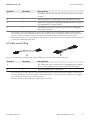
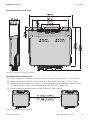
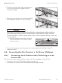
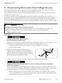
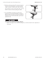
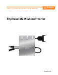
1
Installation Manual
SUNNY BOY 240-US
SUNNY MULTIGATE-US
SMG-SB240US-IA-en-14 | Version 1.4
AMERICAN ENGLISH
Legal Provisions
SMA America, LLC
Legal Provisions
Copyright © 2014 SMA America, LLC. All rights reserved.
No part of this document may be reproduced, stored in a retrieval system, or transmitted, in any
form or by any means, be it electronic, mechanical, photographic, magnetic or otherwise, without
the prior written permission of SMA America, LLC.
Neither SMA America, LLC nor SMA Solar Technology Canada Inc. makes representations,
express or implied, with respect to this documentation or any of the equipment and/or software it
may describe, including (with no limitation) any implied warranties of utility, merchantability, or
fitness for any particular purpose. All such warranties are expressly disclaimed. Neither SMA
America, LLC nor its distributors or dealers nor SMA Solar Technology Canada Inc. nor its
distributors or dealers shall be liable for any indirect, incidental, or consequential damages under
any circumstances.
(The exclusion of implied warranties may not apply in all cases under some statutes, and thus the
above exclusion may not apply.)
Specifications are subject to change without notice. Every attempt has been made to make this
document complete, accurate and up-to-date. Readers are cautioned, however, that
SMA America, LLC and SMA Solar Technology Canada Inc. reserve the right to make changes
without notice and shall not be responsible for any damages, including indirect, incidental or
consequential damages, caused by reliance on the material presented, including, but not limited to,
omissions, typographical errors, arithmetical errors or listing errors in the content material.
All trademarks are recognized even if these are not marked separately. Missing designations do
not mean that a product or brand is not a registered trademark.
The BLUETOOTH® word mark and logos are registered trademarks of Bluetooth SIG, Inc. and any
use of such marks by SMA America, LLC and SMA Solar Technology Canada Inc. is under license.
Modbus® is registered trademark of Schneider Electric and is licensed by Modbus Organization,
Inc.
QR Code is a registered trademark of DENSO WAVE INCORPORATED.
Phillips® and Pozidriv® are registered trademarks of Phillips Screw Company.
Torx® is a registered trademark of Acument Global Technologies, Inc.
SMA America, LLC
3801 N. Havana Street
Denver, CO 80239 U.S.A.
SMA Solar Technology Canada Inc.
2425 Matheson Blvd. E
7th Floor
Mississauga, ON L4W 5K4
Canada
2
SMG-SB240US-IA-en-14
Installation Manual
Important Safety Instructions
SMA America, LLC
Important Safety Instructions
SAVE THESE INSTRUCTIONS
This manual contains important instructions for the following products:
• SB 240-US-10 (Sunny Boy 240-US)
• Multigate-US-10 (Sunny Multigate-US)
This manual must be followed during installation and maintenance.
The product is designed and tested in accordance with international safety requirements, but as
with all electrical and electronic equipment, certain precautions must be observed when installing
and/or operating the product. To reduce the risk of personal injury and to ensure the safe
installation and operation of the product, you must carefully read and follow all instructions,
cautions and warnings in this manual.
Warnings in this Document
A warning describes a hazard to equipment or personnel. It calls attention to a procedure or
practice, which, if not correctly performed or adhered to, could result in damage to or destruction
of part or all of the SMA equipment and/or other equipment connected to the SMA equipment or
personal injury.
Symbol
Description
DANGER indicates a hazardous situation which, if not avoided, will
result in death or serious injury.
WARNING indicates a hazardous situation which, if not avoided,
could result in death or serious injury.
CAUTION indicates a hazardous situation which, if not avoided,
could result in minor or moderate injury.
NOTICE is used to address practices not related to personal injury.
Warnings on this Product
The following symbols are used as product markings with the following meanings.
Symbol
Description
Warning regarding dangerous voltage
The product works with high voltages. All work on the product must
only be performed as described in the documentation of the product.
Installation Manual
SMG-SB240US-IA-en-14
3
Important Safety Instructions
Symbol
SMA America, LLC
Description
Beware of hot surface
The product can become hot during operation. Do not touch the
product during operation.
Observe the operating instructions
Read the documentation of the product before working on it. Follow
all safety precautions and instructions as described in the documentation.
4
SMG-SB240US-IA-en-14
Installation Manual
SMA America, LLC
General Warnings
General Warnings
All electrical installations must be made in accordance with the local and National Electrical
Code® ANSI/NFPA 70 or the Canadian Electrical Code® CSA C22.1. This document does not
and is not intended to replace any local, state, provincial, federal or national laws, regulations or
codes applicable to the installation and use of the product, including without limitation applicable
electrical safety codes. All installations must conform with the laws, regulations, codes and
standards applicable in the jurisdiction of installation. SMA assumes no responsibility for the
compliance or noncompliance with such laws or codes in connection with the installation of the
product.
The product contains no user-serviceable parts.
For all repair and maintenance, always return the unit to an authorized SMA Service Center.
Before installing or using the product, read all of the instructions, cautions, and warnings in this
manual.
Before connecting the product to the electrical utility grid, contact the local utility company. This
connection must be made only by qualified personnel.
Wiring of the product must be made by qualified personnel only.
Installation Manual
SMG-SB240US-IA-en-14
5
Table of Contents
SMA America, LLC
Table of Contents
1
Information on this Document .................................................
1.1
1.2
1.3
1.4
1.5
2
Validity .................................................................................................
Target Group.......................................................................................
Additional Information ........................................................................
Symbols................................................................................................
Nomenclature......................................................................................
9
9
9
9
9
10
Safety......................................................................................... 11
2.1
2.2
Intended Use ....................................................................................... 11
Safety Information ............................................................................... 13
3
Scope of Delivery...................................................................... 16
4
Product Description................................................................... 18
4.1
4.2
4.3
4.4
4.5
5
Sunny Boy............................................................................................
Sunny Multigate ..................................................................................
LED Signals ..........................................................................................
Symbols on Products ...........................................................................
Communication....................................................................................
Mounting ................................................................................... 24
5.1
5.2
Requirements for Mounting the Inverter............................................. 24
Mounting the Inverter.......................................................................... 27
5.2.1
5.2.2
5.3
5.4
Mounting the Sunny Multigate on the Wall................................. 32
Mounting the Sunny Multigate on the Top-Hat Rail..................... 33
Electrical Connection................................................................. 34
6.1
6.2
Safety during Electrical Connection ................................................... 34
Overview of the Connection Areas.................................................... 35
6.2.1
6.2.2
6.3
6
Mounting the Inverter on the Roof ................................................ 27
Mounting the Inverter on the Wall................................................ 28
Requirements for Mounting the Sunny Multigate.............................. 29
Mounting the Sunny Multigate........................................................... 32
5.4.1
5.4.2
6
18
19
20
22
22
Sunny Boy....................................................................................... 35
Sunny Multigate ............................................................................. 36
AC Cabling of the Inverters ................................................................ 36
SMG-SB240US-IA-en-14
Installation Manual
SMA America, LLC
6.4
6.5
6.6
Assembling the AC Field Plug............................................................. 38
Connecting Additional Grounding..................................................... 41
Connecting the First Inverter to the Sunny Multigate ........................ 43
6.6.1
6.6.2
6.7
6.8
6.9
Table of Contents
Connecting the AC Cable to the AC Field Plug or to the
Junction Box ................................................................................... 43
Connecting the AC Cable to Sunny Multigate ............................ 45
Connecting the Sunny Multigate to the Utility Grid .......................... 47
Grounding the Metal Industrial Enclosure ......................................... 49
Connecting the PV Modules to the Inverters ..................................... 49
7
Commissioning the PV System................................................. 51
8
Configuration ............................................................................ 52
8.1
8.2
8.3
8.4
8.5
8.6
8.7
9
Configuration Procedure.....................................................................
Connecting the Sunny Multigate to the Network..............................
Registering the Sunny Multigate in Sunny Portal...............................
Connecting the Sunny Multigate to Sunny Explorer .........................
Changing Operating Parameters.......................................................
Deactivating the Webconnect Function.............................................
Adjustable Parameters ........................................................................
52
52
53
54
54
55
55
Disconnecting the Inverter from Voltage Sources.................. 57
10 Disconnecting the Sunny Multigate from Voltage Sources ... 59
11 Troubleshooting ........................................................................ 60
11.1 Error Messages ................................................................................... 60
11.2 Checking the PV System for Ground Faults ....................................... 66
12 Recommissioning the Inverter.................................................. 68
13 Decommissioning...................................................................... 70
13.1 Disconnecting the AC Field Plug ........................................................ 70
13.2 Decommissioning the Inverter............................................................. 71
13.3 Decommissioning the Sunny Multigate.............................................. 71
14 Technical Data........................................................................... 73
14.1 Requirements for the PV Modules ...................................................... 73
14.2 Sunny Boy 240-US.............................................................................. 73
Installation Manual
SMG-SB240US-IA-en-14
7
Table of Contents
SMA America, LLC
14.3 Sunny Multigate-US ............................................................................ 76
14.4 Torques of AC Field Plugs................................................................... 77
15 Spare Parts and Accessories.................................................... 78
16 Contact....................................................................................... 80
8
SMG-SB240US-IA-en-14
Installation Manual
1 Information on this Document
SMA America, LLC
1 Information on this Document
1.1 Validity
This document is valid for the following device types:
• SB 240-US-10 (Sunny Boy 240-US)
• Multigate-US-10 (Sunny Multigate-US)
1.2 Target Group
The tasks described in this document must only be performed by qualified persons. Qualified
persons must have the following skills:
• Knowledge of how an inverter works and is operated
• Training in how to deal with the dangers and risks associated with installing and using
electrical devices and installations
• Training in the installation and commissioning of electrical devices and installations
• Knowledge of the applicable standards and directives
• Knowledge of and compliance with this document and all safety information
1.3 Additional Information
Links to additional information can be found at www.SMA-Solar.com:
Document title
Document type
"Micro Inverters in Sunny Portal"
Monitoring and Visualization of Micro Inverters in Sunny Portal
User Manual
"Sunny Explorer"
Software for Visualizing and Administering a Speedwire System
User Manual
"Order Form for the SMA Grid Guard Code"
Certificate
1.4 Symbols
Symbol
Explanation
Indicates a hazardous situation which, if not
avoided, will result in death or serious injury
Indicates a hazardous situation which, if not
avoided, can result in death or serious injury
Indicates a hazardous situation which, if not
avoided, can result in minor or moderate injury
Indicates a situation which, if not avoided, can
result in property damage
Information that is important for a specific topic
or goal, but is not safety-relevant
Installation Manual
SMG-SB240US-IA-en-14
9
1 Information on this Document
Symbol
SMA America, LLC
Explanation
Indicates a requirement for meeting a specific
goal
Desired result
A problem that might occur
1.5 Nomenclature
Complete designation
Designation in this document
SMA America Production, LLC
SMA
SMA Solar Technology Canada Inc.
SMA
SMA Speedwire
Speedwire
PV system
PV system
Sunny Boy 240-US*
Sunny Boy, inverter, micro inverter, product
Sunny Multigate-US
Sunny Multigate, communication
unit, product
Inverter which is located at the beginning of the PV system and First inverter
is connected directly to the Sunny Multigate via the AC cable
Inverter which is located at the end of the PV system and not di- Last inverter
rectly connected to the Sunny Multigate
* The terms "Sunny Boy", "Sunny Boy 240-US", "micro inverter" and "inverter" are synonymous in this
document. For simplicity, the general term "inverter" is often used.
10
SMG-SB240US-IA-en-14
Installation Manual
2 Safety
SMA America, LLC
2 Safety
2.1 Intended Use
Sunny Boy 240-US
The Sunny Boy is a micro inverter for PV systems that converts the direct current from a PV module
into grid-compliant alternating current. The alternating current generated is fed into the utility grid
via the Sunny Multigate-US.
Figure 1: Design of a PV system with Sunny Boy 240-US and Sunny Multigate-US
The product is suitable for indoor and outdoor use.
Installation Manual
SMG-SB240US-IA-en-14
11
2 Safety
SMA America, LLC
The Sunny Boy must only be connected to a single PV module. The PV module used must comply
with protection class II as per IEC 61730, application class A and must be suitable for use with the
Sunny Boy. The Sunny Boy must be operated with the Sunny Multigate.
• Do not connect any loads between the Sunny Boy and the Sunny Multigate.
• Do not connect any loads between the individual Sunny Boys.
• Do not open the lid of the Sunny Boy.
• Only mount the Sunny Boy on the framework mounted on the roof directly under the PV
modules or on the wall.
• Do not mount the Sunny Boy directly on the module frame.
• Do not mount the Sunny Boy on flammable construction materials.
• Do not mount the Sunny Boy in areas containing highly flammable materials.
• Do not mount the Sunny Boy in potentially explosive atmospheres.
All components must remain within their permitted operating ranges at all times.
The product must only be used in countries for which it is approved or released by SMA and the
grid operator.
Use this product only in accordance with the information provided in the enclosed documentation
and with the locally applicable standards and directives. Any other application may cause
personal injury or property damage.
Alterations to the product, e.g. changes or modifications, are only permitted with the express written
permission of SMA. Unauthorized alterations will void guarantee and warranty claims and usually
void the operation permit. SMA shall not be held liable for any damage caused by such changes.
Any use of the product other than that described in the Intended Use section does not qualify as
appropriate.
The enclosed documentation is an integral part of this product. Keep the documentation in a
convenient place for future reference and observe all instructions contained therein.
The type label must remain permanently attached to the product.
12
SMG-SB240US-IA-en-14
Installation Manual
2 Safety
SMA America, LLC
Sunny Multigate
The Sunny Multigate is a communication unit and forms the electrical connection point of the PV
system with a maximum of twelve micro inverters to the utility grid. The Sunny Multigate is
connected between the micro inverters and the utility grid to feed the alternating current of the
micro inverters collectively into the utility grid.
The product is designed for indoor use only.
The Sunny Multigate must always be installed in a dust-tight and water-tight industrial enclosure
complying with the fire protection class 5VA and pollution degree 3. For indoor use, an industrial
enclosure Type 1 with back panel complying with UL50 is required. For outdoor use, an industrial
enclosure Type 3 with back panel complying with UL50E is required.
• A maximum of twelve micro inverters can be connected to the Sunny Multigate.
• No loads must be connected between the Sunny Boy and the Sunny Multigate.
• No loads must be connected between the Sunny Multigate and the circuit breaker.
• The grounding conductor of the AC cable from the inverter must be connected to the
Sunny Multigate.
• The grounding conductor of the utility grid must be connected to the grounding conductor
terminal of the Sunny Multigate.
• The Sunny Multigate must not be opened.
All components must remain within their permitted operating ranges at all times.
The product must only be used in countries for which it is approved or released by SMA and the
grid operator.
Use this product only in accordance with the information provided in the enclosed documentation
and with the locally applicable standards and directives. Any other application may cause
personal injury or property damage.
Alterations to the product, e.g. changes or modifications, are only permitted with the express written
permission of SMA. Unauthorized alterations will void guarantee and warranty claims and usually
void the operation permit. SMA shall not be held liable for any damage caused by such changes.
Any use of the product other than that described in the Intended Use section does not qualify as
appropriate.
The enclosed documentation is an integral part of this product. Keep the documentation in a
convenient place for future reference and observe all instructions contained therein.
The type label must remain permanently attached to the product.
2.2 Safety Information
This section contains safety information that must be observed at all times when working on or with
the product.
To prevent personal injury and property damage and to ensure long-term operation of the product,
read this section carefully and observe all safety information at all times.
Installation Manual
SMG-SB240US-IA-en-14
13
2 Safety
SMA America, LLC
Danger to life due to high voltages of the PV modules
When exposed to sunlight, the PV modules generate dangerous DC voltage which is present in
the DC conductors. Touching the DC conductors can lead to lethal electric shocks. If you
disconnect the DC connectors from the inverter under load, an electric arc may occur leading to
electric shock and burns.
• Do not touch uninsulated cable ends.
• Do not touch the DC conductors.
• Do not open the inverter and the Sunny Multigate.
• Disconnect the inverter from all voltage sources before performing any work on it (see
Section 9, page 57).
• Before working on the Sunny Multigate, always disconnect it from all voltage sources (see
Section 10, page 59).
• Follow the instructions precisely.
• Observe the warning messages on the inverter and the Sunny Multigate.
Risk of electric shock due to ground fault
If a ground fault occurs, parts of the system may still be live. Touching live components can lead
to lethal electric shocks.
• Prior to touching any components, always disconnect the inverter from all voltage sources as
described in this document (see Section 9, page 57).
• Prior to touching any components, always disconnect the Sunny Multigate from all voltage
sources as described in this document (see Section 10, page 59).
Risk of electric shock due to damaged devices
Operating a damaged inverter or Sunny Multigate can lead to hazardous situations that result in
lethal electric shocks.
• Only operate the inverter and the Sunny Multigate provided that they are in safe and full
working order.
• Regularly check for visible damage.
14
SMG-SB240US-IA-en-14
Installation Manual
2 Safety
SMA America, LLC
Risk of burns due to hot surfaces
The surfaces of the inverter and the Sunny Multigate can get very hot. Touching the surface can
result in burns.
• Mount the inverter in such a way that it cannot be touched inadvertently.
• Do not touch hot surfaces.
• Wait ten minutes for the surface to cool sufficiently before performing any work on the
inverter.
• Observe the warning messages on the inverter and the Sunny Multigate.
Damage to the inverter due to moisture and dust intrusion
Dust or moisture intrusion can damage the inverter and impair its functionality.
• Seal all inverter pin connectors with the appropriate plugs or protective caps.
Damage to the Sunny Multigate from moisture and dust intrusion
Dust or moisture intrusion can damage the Sunny Multigate and impair its functionality. The
Sunny Multigate must always be installed in an industrial enclosure in accordance with UL50E.
This will ensure that the Sunny Multigate is protected against dust and moisture and is suitable for
indoor and outdoor operation.
• For indoor use, always install the Sunny Multigate in a type 1 industrial enclosure with
pollution degree 3.
• For outdoor use, always install the Sunny Multigate in a type 3 industrial enclosure with
pollution degree 3.
Damage to the Sunny Multigate due to the use of cleaning agents
The use of cleaning agents may cause damage to components of the Sunny Multigate. If the
Sunny Multigate is dirty or dusty, you can clean the enclosure, the ventilation slots, the type label,
and the LEDs with a dry brush.
• Disconnect the Sunny Multigate from all voltage sources (see Section 10, page 59).
• Only clean the Sunny Multigate with a dry brush.
Damage to the inverter due to the use of cleaning agents
• If the inverter is dirty, clean the enclosure, the enclosure lid and the type label only using
clear water and a cloth.
Installation Manual
SMG-SB240US-IA-en-14
15
3 Scope of Delivery
SMA America, LLC
3 Scope of Delivery
Check the scope of delivery for completeness and any externally visible damage. Contact your
distributor if the scope of delivery is incomplete or damaged.
Sunny Boy
Figure 2: Components included in the scope of delivery of the inverter
Position
Quantity
Designation
A
1
Inverter
B
1
Supplementary sheet for the inverter, Production Test Report
C
1
Grounding bolt
D
1
Clamping bracket for equipment grounding
E
1
Washer for equipment grounding
F
2
Hexagon nut for equipment grounding
Sunny Multigate-US
Figure 3: Elements included in the scope of delivery of the Sunny Multigate
Position
Quantity
Designation
A
1
Sunny Multigate
B
1
AC field plug: insulator, enclosure, seal, screw connection
16
SMG-SB240US-IA-en-14
Installation Manual
3 Scope of Delivery
SMA America, LLC
Position
Quantity
Designation
C
1
Protective cap for the unused AC pin connector on the last
inverter*
D
1
Warning labels for attaching to the industrial enclosure
E
1
Label with registration ID (RID) and identification key (PIC)
for registration in Sunny Portal**
F
1
Installation manual for Sunny Boy and Sunny Multigate,
mounting overview
* Last inverter: in this document, the inverter that is located at the end of the PV system and not directly
connected to the Sunny Multigate but only to one other inverter, is referred to as the "last inverter". An
AC pin connector remains unused on the last inverter and must be closed with a protective cap.
** Keep this label with your access data for registration in Sunny Portal. The access data can also be found
on the Sunny Multigate type label.
AC Cable and DC Plug
Figure 4: Components included in the scope of delivery of the AC cable and the DC plug
Position
Quantity
Designation
A
1
AC cable with two connectors for connecting two inverters
or for connecting the first inverter to the AC field plug*
1
DC plug with two DC connectors**
B
* First inverter: The inverter that is located at the beginning of the PV system and is directly connected to
the Sunny Multigate via the AC cable is called "first inverter" in this document. AC cables are plugged
into both AC pin connectors at the first inverter.
** The DC connectors illustrated may deviate from your order.
Installation Manual
SMG-SB240US-IA-en-14
17
4 Product Description
SMA America, LLC
4 Product Description
4.1 Sunny Boy
The Sunny Boy is a micro inverter for PV systems that converts the direct current from a PV module
into grid-compliant alternating current. The alternating current generated is fed into the utility grid
via the Sunny Multigate-US.
Figure 5: Design of the Sunny Boy
Position
Explanation
A
Type label
The type label uniquely identifies the inverter. You will require the information
on the type label to use the product safely and when seeking customer support from the SMA Service Line. You will find the following information on the
type label:
• Device type (Model)
• Serial number (Serial No.)
• Date of manufacture
• Device-specific characteristics
B
Pin connectors for the AC connectors
C
Pin connector for DC plug
D
Removable label with inverter serial number
To enable clear identification of the inverters of a PV system, e.g. under fault
conditions, this label can be applied to the enclosed mounting overview.
18
SMG-SB240US-IA-en-14
Installation Manual
4 Product Description
SMA America, LLC
4.2 Sunny Multigate
The Sunny Multigate is a communication unit and forms the electrical connection point of the PV
system with a maximum of twelve micro inverters to the utility grid. The Sunny Multigate is
connected between the micro inverters and the utility grid to feed the alternating current of the
micro inverters collectively into the utility grid.
Figure 6: Design of the Sunny Multigate
Position
Explanation
A
Press-out brackets for mounting with screws
B
Screw terminal for AC input (inverter)
Labeling: Inverter
C
LEDs
The upper LED indicates the operating state of the inverters. The lower LED indicates the operating state of the Sunny Multigate. Depending on the operating state, the LEDs are glowing green, red or orange, or are off (see Section 4.3 "LED Signals", page 20).
D
Interface for optional communication
E
The type label provides a clear identification of the Sunny Multigate. You will
require the information on the type label to use the product safely and when
seeking customer support from the SMA Service Line. You will find the following information on the type label:
• Device type (Model)
• Serial number (Serial No.)
• Registration ID (RID) for registration in Sunny Portal
• Identification key (PIC) for registration in Sunny Portal
• Device-specific characteristics
F
Screw terminal for AC output (utility grid)
Labeling: Grid
G
Pin connector for connecting the network cable (RJ45)
Installation Manual
SMG-SB240US-IA-en-14
19
4 Product Description
SMA America, LLC
4.3 LED Signals
The LEDs on the Sunny Multigate indicate the operating state of the PV system.
Figure 7: Position of the LEDs on the Sunny Multigate
The upper LED is labeled with Inverter and indicates the operating state of the inverters.
The lower LED is labeled with Multigate and indicates the operating state of the Sunny Multigate.
LED
Status
Explanation
A: LED Inverter
off
The communication with the inverters is not active.
glowing green
The inverters are in operation.
glowing orange
At least one of the connected inverters is in Warning
mode. You will find the detailed error message in Sunny Portal or Sunny Explorer. You can find the cause and
its corrective measure in this document (see Section 11
"Troubleshooting", page 60).
glowing red
At least one of the connected inverters is in Fault mode.
You will find the detailed error message in Sunny Portal or
Sunny Explorer. You can find the cause and its corrective
measure in this document (see Section 11 "Troubleshooting", page 60).
20
SMG-SB240US-IA-en-14
Installation Manual
4 Product Description
SMA America, LLC
LED
Status
B: LED Multigate off
Installation Manual
Explanation
Either there is no AC voltage present or the Sunny Multigate is defective.
glowing green
The Sunny Multigate is in normal operating state.
glowing orange
The Sunny Multigate is in Warning mode.
1. If communication is still possible, determine the
respective error message in Sunny Portal or
Sunny Explorer. You can find the cause and its
corrective measure in this document (see Section 11
"Troubleshooting", page 60).
2. If no communication is possible, disconnect the
network cable from the Sunny Multigate and
reconnect the Sunny Multigate to the network (see
Section 8.2 "Connecting the Sunny Multigate to the
Network", page 52).
3. If the error persists, disconnect the Sunny Multigate
from all voltage sources (see Section 10
"Disconnecting the Sunny Multigate from Voltage
Sources", page 59) and reconnect it (see
Section 6.7 "Connecting the Sunny Multigate to the
Utility Grid", page 47).
4. If the error persists, contact the SMA Service Line.
glowing red
The Sunny Multigate is in Fault mode.
1. If communication is still possible, determine the
respective error message in Sunny Portal or
Sunny Explorer. You can find the cause and its
corrective measure in this document (see Section 11
"Troubleshooting", page 60).
2. If no communication is possible, disconnect the
network cable from the Sunny Multigate and
reconnect the Sunny Multigate to the network (see
Section 8.2 "Connecting the Sunny Multigate to the
Network", page 52).
3. If the error persists, disconnect the Sunny Multigate
from all voltage sources (see Section 10
"Disconnecting the Sunny Multigate from Voltage
Sources", page 59) and reconnect it (see
Section 6.7 "Connecting the Sunny Multigate to the
Utility Grid", page 47).
4. If the error persists, contact the SMA Service Line.
SMG-SB240US-IA-en-14
21
4 Product Description
SMA America, LLC
4.4 Symbols on Products
Symbol
Explanation
Grounding conductor
This symbol indicates the position for the grounding conductor terminal.
Danger to life due to high voltages
The product operates at high voltages. All work on the product must be
carried out by qualified persons only.
Risk of burns due to hot surfaces
The product can get hot during operation. Avoid contact during operation. Allow the product to cool down sufficiently before carrying out any
work. Wear personal protective equipment such as safety gloves.
Observe the documentation.
Observe all documentation supplied with the product.
Evaluated to the requirements of the Underwriters Laboratories Standard
for Safety for Inverters, Converters, Controllers and Interconnection System Equipment for Use With Distributed Energy Resources, UL 1741.
FCC designation
The product complies with the requirements of the applicable FCC standards.
WEEE designation
Do not dispose of the product together with the household waste but in
accordance with the locally applicable disposal regulations for electronic
waste.
4.5 Communication
Communication between Inverter and Sunny Multigate
The inverter is connected to the Sunny Multigate via the AC cable. The communication and data
transmission between the Sunny Multigate and the inverters takes place via a PLC interface.
22
SMG-SB240US-IA-en-14
Installation Manual
SMA America, LLC
4 Product Description
Communication between Sunny Multigate and Other Communication Products
Figure 8: Example of a PV system with micro inverters and Sunny Multigate with communication via Speedwire/
Webconnect
Communication between the Sunny Multigate and other SMA communication products (e.g.
Sunny Explorer, Sunny Portal) takes place via Speedwire/Webconnect. Speedwire is a type of
communication based on Ethernet. You can connect the Sunny Multigate to your network via
Speedwire. Webconnect enables data exchange between Sunny Multigate and Sunny Portal. In
order to establish a connection to Sunny Portal, the Sunny Multigate must be connected to a router
or modem with Internet connection and be integrated into the local network. To enable data
exchange between Sunny Multigate and Sunny Portal, you must register the PV system in
Sunny Portal (see Section 8.3 "Registering the Sunny Multigate in Sunny Portal", page 53). If you
do not want to use the Webconnect function, you can deactivate it in Sunny Explorer (see
Section 8.6 "Deactivating the Webconnect Function", page 55).
Installation Manual
SMG-SB240US-IA-en-14
23
5 Mounting
SMA America, LLC
5 Mounting
5.1 Requirements for Mounting the Inverter
Requirements for the mounting location:
Danger to life due to fire or explosion
Despite careful construction, electrical devices can cause fires.
• Do not mount the inverter in areas containing highly flammable materials or gases.
• Do not mount the inverter in a potentially explosive atmosphere.
Risk of burns due to hot surfaces
The surface of the inverter can get very hot. Touching the surface can result in burns.
• Mount the inverter in such a way that it cannot be touched inadvertently.
• Do not touch hot surfaces.
• Wait ten minutes for the surface to cool sufficiently before performing any work on the
inverter.
• Observe the warning messages on the inverter.
☐ To ensure optimum operation, the ambient temperature should be between -40°C (-40°F) and
65°C (-149°F).
☐ The mounting location should not be exposed to direct solar irradiation. Direct solar irradiation
can cause the inverter to overheat. As a result, the inverter reduces its power output.
☐ Climatic conditions must be met (see Section 14 "Technical Data", page 73).
☐ The mounting location must be inaccessible to children.
☐ The mounting location must be suitable for the weight and dimensions of the inverter (see
Section 14 "Technical Data", page 73).
☐ The inverter must be mounted on the roof on the framework underneath the PV modules or on
a solid support surface (e.g. concrete, brickwork). In living areas, ensure that the support
surface is not drywall or similar. When in operation, the inverter makes noises which can be
perceived as a nuisance.
☐ When mounting on the framework, the mounting position should preferably be in the center of
the PV module. This will ensure a longer electrical endurance of the inverter.
24
SMG-SB240US-IA-en-14
Installation Manual
5 Mounting
SMA America, LLC
Dimensions for mounting:
Figure 9: Position of the anchoring points
Recommended clearances:
☐ When using an AC cable of 1.40 m (4.6 ft): min. 50 mm (2.0 in) to max. 1.10 m (3.6 ft)
☐ When using an AC cable of 2.0 m (6.6 ft): min. 50 mm (2.0 in) to max. 1.70 m (5.6 ft)
☐ Greater distances between two inverters can be bridged using an additional cable and two
AC field plugs (see Section 6.4 "Assembling the AC Field Plug", page 38).
☐ Observe recommended clearances to the inverters or other objects.
Figure 10: Recommended clearances
Installation Manual
SMG-SB240US-IA-en-14
25
5 Mounting
SMA America, LLC
Minimum Clearance between Inverter and PV Module Bottom Side:
Damage to the PV module due to insufficient clearance between the inverter and the
PV module bottom side
For roof mounting, the clearance from the inverter to the bottom side of the PV module must be at
least 30 mm (1.2 in). This will prevent the grounding bolt from damaging the PV module.
Figure 11: Minimum clearance of the inverter to the bottom side of the PV module
Permitted Mounting Position:
Electric shock due to ingress of moisture
• During mounting, make sure that the connection area of the inverter remains dry.
As soon as the connector and protective cap are plugged in, the connection area will be
protected from moisture ingress. Thus, the inverter complies with degree of protection Type
4X.
☐ In order to ensure optimum operation and long electrical endurance of the inverter, install
each inverter centered under the respective connection socket of the PV module.
☐ For installations that are integrated into the building, do not install the inverter directly on the
back side of the PV module. This will prevent the inverter power from being reduced due to
excessive ambient temperature.
26
SMG-SB240US-IA-en-14
Installation Manual
5 Mounting
SMA America, LLC
5.2 Mounting the Inverter
5.2.1
Mounting the Inverter on the Roof
Risk of falling when working on the roof
There is a risk of falling or slipping when working on the rooftop. Observe the applicable
accident prevention regulations for work on rooftops.
• Before stepping on the rooftop, ensure the load bearing capacity of all parts subjected to
load.
• In accordance with the accident prevention regulations, a safety harness must be worn or a
safety scaffold must be used.
• Use a fall protection.
When mounting the inverter on the roof underneath the PV modules, proceed as follows.
You can mount the inverter with the back panel or with the enclosure lid to the roof. SMA
recommends mounting the inverter with the enclosure lid to the roof. This will allow for better heat
dissipation. Observe the minimum clearance of the inverter to the PV module (see Section 5.1
"Requirements for Mounting the Inverter", page 24).
Information on the figures in this section
The figures show the recommended mounting option for the inverter with the lid facing the
roof. The procedure for mounting the inverter with the back panel facing the roof is identical
and is not depicted in the figures in this section.
Position of the inverter
In order to ensure optimum operation and long electrical endurance of the inverter, install
each inverter centered under the respective junction box of the PV module.
Additionally required mounting material (not included in the scope of delivery):
☐ The required fastening material must be selected according to the profile rail used.
☐ The mounting material must be made of stainless steel.
☐ Diameter of the screws: maximum M8 (0.3 in)
Damage to the PV module due to screws being too long
The length of the screws must be suitable for the clearance between the inverter and the PV
module bottom side.
• Make sure that the PV module is not damaged by the screws being used.
There are several options for attaching the inverter to the framework on the roof. In the following
example, mounting with T-head bolts is described.
Installation Manual
SMG-SB240US-IA-en-14
27
5 Mounting
SMA America, LLC
Procedure:
1. Keep the supplied mounting overview at hand for the allocation of the inverters to the PV
modules.
2. In case the connection area points upwards during mounting, make sure to protect the plugs
and pin connectors against ingress of moisture.
3. Remove the label with the inverter serial number from the inverter and attach it to the
corresponding position in the mounting overview included in the delivery.
4. Insert the T-head bolts into the profile rail and
turn by 90°. This will firmly anchor the screws in
the profile rail.
5. Position the inverter on the anchored screws.
Insert the screws into the oblong holes in the
enclosure as far as the required fastening point.
6. Attach the inverter using suitable washers and
nuts.
7. Ensure that the inverter is securely in place.
5.2.2
Mounting the Inverter on the Wall
To mount the inverter on the wall, proceed as follows.
Additionally required mounting material (not included in the scope of delivery):
☐ The mounting material must be made of stainless steel.
☐ Two screws suitable for the support surface
☐ Two washers suitable for the screws
☐ Two screw anchors suitable for the support surface and the screws
Procedure:
1.
Risk of injury due to damaged cables
There may be power lines or other supply lines (e.g. gas or water) routed in the wall.
• Ensure that no lines are laid in the wall which could be damaged when drilling holes.
28
SMG-SB240US-IA-en-14
Installation Manual
5 Mounting
SMA America, LLC
2. Mark the position of the drill holes using the holes in the enclosure. For this, use the two outer
holes or the two oblong holes in the middle.
3. Drill the holes and insert the screw anchors.
4. Align the inverter with the drill holes and attach it
using suitable screws and washers.
5.3 Requirements for Mounting the Sunny Multigate
Requirements for the mounting location:
Danger to life due to fire or explosion
Despite careful construction, electrical devices can cause fires.
• Do not mount the Sunny Multigate in areas containing highly flammable materials or gases.
• Do not mount the Sunny Multigate in potentially explosive atmospheres.
Danger of fire due to non-UL50E industrial enclosure
The Sunny Multigate is only protected against fire if it is installed in an industrial enclosure
complying with UL50E. Otherwise, the fire risk could lead to personal injury and property
damage.
• For indoor use, always install the Sunny Multigate in a type 1 industrial enclosure with
pollution degree 3.
• For outdoor use, always install the Sunny Multigate in a type 3 industrial enclosure with
pollution degree 3.
Damage to the Sunny Multigate from moisture and dust intrusion
Dust or moisture intrusion can damage the Sunny Multigate and impair its functionality. The
Sunny Multigate must always be installed in an industrial enclosure with back panel complying
with UL50E. This will ensure that the Sunny Multigate is protected against dust and moisture and
is suitable for indoor and outdoor operation.
• For indoor use, always install the Sunny Multigate in a type 1 industrial enclosure with
pollution degree 3.
• For outdoor use, always install the Sunny Multigate in a type 3 industrial enclosure with
pollution degree 3.
Installation Manual
SMG-SB240US-IA-en-14
29
5 Mounting
SMA America, LLC
☐ The mounting location must be suitable for the installation of the Sunny Multigate in an
industrial enclosure of type 1 or type 3.
☐ The mounting location must be suitable for the weight and dimensions of the industrial
enclosure with the Sunny Multigate (see Section 14 "Technical Data", page 73).
☐ The mounting location must be inaccessible to children.
☐ AC cable route of the entire PV system with Sunny Multigate: maximum 30 m (100 ft)
When installing several Sunny Multigate devices in a PV system, you must lay the AC cable of
each Sunny Multigate to the respective inverter separately in order to guarantee trouble-free
communication between the Sunny Multigate and the inverter.
Figure 12: Maximum AC cable route of the PV system (left: last inverter; right: first inverter connected to
Sunny Multigate).
☐ A robust support surface must be available for mounting the device, e.g. concrete, walls. In
living areas, ensure that the support surface is not drywall or similar.
☐ The mounting location should be freely and safely accessible at all times without the need for
any auxiliary equipment (such as scaffolding or lifting platforms). Non-fulfillment of these
criteria may restrict servicing.
☐ The mounting location should not be exposed to direct solar irradiation.
☐ Climatic conditions must be met (see Section 14 "Technical Data", page 73).
☐ The ambient temperature must be between -40°C (-40°F) and 25°C (113°F). This will ensure
optimal operation of the Sunny Multigate.
Requirements for the industrial enclosure:
☐ Industrial enclosure with back panel complying with UL50E, Type 3 for outdoor use or Type 1
for indoor use
☐ Pollution degree 3
☐ Material: plastic or metal
☐ Minimum dimensions (W x H x D): 260 mm x 240 mm x 120 mm (10.3 in x 9.5 in x 4.7 in)
☐ Minimum volume: 19 liters
☐ Fire protection class: minimum UL 94 5VA
30
SMG-SB240US-IA-en-14
Installation Manual
5 Mounting
SMA America, LLC
☐ Operating temperature range: −40°C to +45°C (−40°F to 113°F)
☐ A warning label with the following text must be available:
"DANGER - Risk of Electric Shock. Do not remove cover. No user serviceable parts inside.
Refer servicing to qualified service personnel."
"DANGER - Hazardous voltage remains for five minutes after disconnecting main power
supply."
Useful hint: You can use the warning label included in the scope of delivery. The warning label
included in the scope of delivery is made of Scotchcal Brand 3690 from 3M and only suitable
for certain surfaces according to UL-listing (see E-File no. MH18072, category PGJI2).
Examples: Alkyd paint, aluminum, Polyester paint, zinc.
Clearances:
☐ The minimum clearance of the Sunny Multigate to the outer walls of the metal industrial
enclosure is 12.7 mm (0.5 in).
☐ Within an industrial closure, observe the following clearances to ensure sufficient ventilation:
Figure 13: Recommended clearances
Position
Dimensions
A
98 mm (3.86 in)
B
150 mm (5.9 in)
Permitted mounting positions of the Sunny Multigate:
☐ Only mount the Sunny Multigate horizontally.
Installation Manual
SMG-SB240US-IA-en-14
31
5 Mounting
SMA America, LLC
Dimensions for mounting the Sunny Multigate with screws:
Figure 14: Dimensions of the Sunny Multigate and the drill holes for mounting with screws
5.4 Mounting the Sunny Multigate
5.4.1
Mounting the Sunny Multigate on the Wall
Additionally required mounting material (not included in the scope of delivery):
☐ Four screws suitable for the size of the brackets and for the material of the back panel
mounted in the industrial enclosure. The maximum permissible height of the screw head of
6 mm (0.2 in) must not be exceeded.
Procedure:
1.
Danger to life due to electric shock
If screws or conductors on the connecting terminal plate are touched, there is a risk of electric
shock.
• To avoid contact between screw and conductor, only use screws with a maximum head
height of 6 mm for mounting on the brackets.
2. Press the four brackets on the back side of the
Sunny Multigate out from the inside.
☑ The brackets snap audibly into place.
3. Mark the drill holes using the brackets as a template.
4. Drill the holes.
32
SMG-SB240US-IA-en-14
Installation Manual
5 Mounting
SMA America, LLC
5. Insert screws with a maximum head height of
6 mm through the brackets and tighten. Make
sure not to damage the brackets.
6. Make sure that the Sunny Multigate is securely in place.
5.4.2
Mounting the Sunny Multigate on the Top-Hat Rail
Additionally required mounting material (not included in the scope of delivery):
☐ Top-hat rail (DIN rail) suitable for the industrial enclosure. Width: 35 mm (1.4 in),
length: 235 mm (9.3 in)
Procedure:
1. For mounting on a top-hat rail, attach the
Sunny Multigate to the top-hat rail from above,
and hook it in.
☑ The Sunny Multigate snaps into place.
2. Make sure that the Sunny Multigate is securely in place.
3. Attach the supplied warning label in a clearly legible position on the outside of the industrial
enclosure lid.
Installation Manual
SMG-SB240US-IA-en-14
33
6 Electrical Connection
SMA America, LLC
6 Electrical Connection
6.1 Safety during Electrical Connection
Danger to life due to electric shock
Do not disconnect under load
PV plug connections must not be disconnected while under load. They can be placed in a no
load state by switching off the DC/AC converter or breaking the AC circuit.
• Make sure that the two-pole circuit breaker is switched off and cannot be reconnected.
• Make sure that the PV modules are covered.
Risk of electric shock due to contact with live components when opening the
Sunny Multigate
There are live components inside the Sunny Multigate. There is a risk of electric shock if you open
the Sunny Multigate.
• Never open the Sunny Multigate.
Danger to life due to electric shock in case of installations without equipment
grounding conductor
In case of installations without equipment grounding conductor, grounding of the inverters is
ensured via the AC cable only. There is a risk of electric shock under fault conditions at the
inverter if PV modules are connected to the inverter and the connection to the grounding
conductor via the Sunny Multigate-US is interrupted.
• Observe the installation sequence (see Section 6 "Electrical Connection", page 34).
• Before disconnecting a single inverter on the AC side: Disconnect all following inverters of
the PV system on the DC side.
Damage to the inverter due to moisture ingress
When the inverter is open, moisture can penetrate and cause damage to the inverter. The
tightness is no longer intact and the function of the inverter cannot be guaranteed.
• Never open the inverter.
Risk of fire
• To reduce the risk of fire, connect only to a circuit provided with 15 A maximum branchcircuit overcurrent protection in accordance with the National Electrical Code® (NE, ANSI/
NFPA 70).
34
SMG-SB240US-IA-en-14
Installation Manual
6 Electrical Connection
SMA America, LLC
Electrical installations
All electrical installations must be carried out in accordance with the local standards and the
National Electrical Code® ANSI/NFPA 70 or the Canadian Electrical Code® CSA C22.1.
• With an ungrounded PV array/PV module the National Electrical Code®, ANSI/NFPA
70 wiring methods are to be used, including Sec. 690.35.
• The DC input and AC output circuits are isolated from the enclosure and that system
grounding, if required by Section 250 of the National Electrical Code®, ANSI/NFPA 70,
is the responsibility of the installer.
• The provisions in the National Electrical Code® article 690.8 (A)(3) for determination of
the maximum micro inverter output circuit current apply to this product.
• The circuit conductors and overcurrent devices are considered to be subjected to the
maximum micro inverter output circuit current and shall be sized to carry not less than
125% of the maximum currents as required by the National Electrical Code® article
690.8(A)(3).
• The overcurrent protection for the AC output circuit is to be provided by the installer.
• If cables of type TC-ER (Tray Cable Exposed Run) are used, the requirements of the
National Electrical Code®, article 336.10 must be observed.
• Make sure that no cables used for electrical connection are damaged.
6.2 Overview of the Connection Areas
6.2.1
Sunny Boy
Figure 15: Connection areas at the bottom of the inverter
Position
Designation
A
DC pin connector Terminal for the DC plug
B
AC pin connector
Installation Manual
Explanation
• For AC cable connection for connecting two inverters
• For connecting the first inverter to the
Sunny Multigate
• For inserting the protective cap on the last inverter
SMG-SB240US-IA-en-14
35
6 Electrical Connection
6.2.2
SMA America, LLC
Sunny Multigate
Figure 16: Connection areas on the Sunny Multigate
Position
Designation
A
Connecting terminal plate for the connection of the AC cable of the inverter, labeling: Inverter
B
Pin connector for connecting the optional communication
C
Pin connector for connecting the network cable (RJ45)
D
Connecting terminal plate for the connection of the AC cable of the utility
grid, labeling: Grid
6.3 AC Cabling of the Inverters
Figure 17: AC cabling among the inverters (left = last inverter; right = first inverter)
36
SMG-SB240US-IA-en-14
Installation Manual
SMA America, LLC
6 Electrical Connection
Requirements:
☐ All electrical installations must be carried out in accordance with all electrical standards
applicable on-site and the National Electrical Code® (NE, ANSI/NFPA 70) (see
National Electrical Code®, paragraph 690.8 (B)(1), paragraph 690.8(A)(3)) or the
Canadian Electrical Code® CSA C22.1.
☐ The maximum output current of the inverter must comply with the National Electrical Code®,
paragraph 690.8 (A)(3).
☐ For fusing purposes, use at maximum a two-pole, 15 A circuit breaker.
☐ No loads must be connected between the individual inverters.
☐ Overcurrent protection must comply with the National Electrical Code®, paragraph 690.9.
☐ For the AC cable connection to the Sunny Boy, only use the AC cable recommended by SMA
(see Section 15 "Spare Parts and Accessories", page 78).
☐ To allow for greater distances between two inverters, use an additional cable and two AC
field plugs (see Section 6.4 "Assembling the AC Field Plug", page 38).
☐ Only use cables of type TC-ER observing the requirements of the National Electrical Code®,
article 336.10.
Procedure:
1.
Danger to life due to electric shock
Do not disconnect the AC connectors under load.
• Ensure that the circuit breaker is switched off and that it cannot be reconnected.
• Make sure that the PV modules are covered.
2. Plug one end of the supplied AC cable into the
outer AC pin connector of the last inverter of the
PV system.
☑ The plug snaps into place.
3. Plug the protective cap into the middle AC pin
connector of the last inverter.
☑ The protective cap snaps into place.
4. Ensure that the AC connector and the protective cap in the inverter pin connectors are securely
in place.
Installation Manual
SMG-SB240US-IA-en-14
37
6 Electrical Connection
SMA America, LLC
5. Plug the other end of the AC cable into the
middle AC pin connector of the next inverter.
6.
7.
8.
9.
☑ The plug snaps into place.
Connect further inverters following the same procedure.
If necessary, use AC field plugs to bridge greater distances (see Section 6.4 "Assembling the
AC Field Plug", page 38)
If necessary, additionally ground the inverters (see Section 6.5 "Connecting Additional
Grounding", page 41).
Connect the free end of the AC cable of the first inverter to the Sunny Multigate (see
Section 6.6, page 43).
6.4 Assembling the AC Field Plug
You can use the AC field plugs included in the delivery for different purposes:
• Connecting the AC cable of the first inverter to the Sunny Multigate. However, this connection
can also be made using a junction box.
• Using two AC field plugs to bridge greater distances between two inverters. The AC cables
available at SMA for connecting the inverters have a limited length (see Section 15 "Spare
Parts and Accessories", page 78).
Overview
Figure 18: Elements of the AC field plug
Position
Designation
A
Insulator
B
Enclosure
C
Seal
D
Screw connection
Additionally required material (not included in the scope of delivery):
☐ 3 bootlace ferrules 2.5 mm² (14 AWG)
☐ Cable complying with UL6703 (PV wire)
☐ Cable shears with insulated handles, 165 mm (6.5 in)
☐ Stripping knife with straight blade, TiN 8 mm to 28 mm (0.3 in to 1.1 in)
☐ Insulation stripping tool, 10 mm² (7 AWG)
38
SMG-SB240US-IA-en-14
Installation Manual
SMA America, LLC
☐
☐
☐
☐
☐
☐
☐
6 Electrical Connection
Crimping tool for bootlace ferrules up to 10 mm² (7 AWG)
Torque screwdriver, 1.4" hexagon socket, 0.3 Nm to 1.2 Nm (2.7 in-lb to 10.6 in-lb)
Cross-head screwdriver bit, 1.4" hexagon, length: 25 mm (1 in)
Torque wrench, scale adjustable from 2 Nm to 20 Nm (17.7 in-lb to 177 in-lb)
Crow-Ring wrench, AF 25
Square insertion tool, outer square: 3/8 in, inner square: 9 mm x 12 mm
Screwdriver, insulated with blade width 4 mm (0.16 in) and blade thickness 0.8 mm (0.03 in)
Danger to life due to electric shock
• Do not disconnect or connect the AC field plug under load.
• Only assemble the AC field plug in a dry environment.
• Observe the operating temperature range of −40°C to +85°C (−40°F to +185°F).
• Note and adhere to the requirements of the National Electrical Code®, ANSI/NFPA 70).
Cable requirements:
☐ Cable type: UL listed as per UL6703 (PV wire, QPOR) Power and Control Tray cable, type TCER (LAPP-Tray Cable II A 3 G AWG 14/46 BK). With this cable type, the use of a conduit is
not required.
☐ Cable type: copper wire
☐ Cable cross-section: 2.5 mm² (14 AWG)
☐ External diameter of the cable sheath: 8.8 mm to 9.6 mm (0.35 in to 0.38 in)
☐ Wire cross-section: 30 AWG
☐ Number of stranded wires: 46
☐ Temperature: at least +90°C (+194°F) wet/dry
☐ This cable must be installed in an inaccessible location or in a National Electrical Code®
compliant conduit.
Removing and reassembling the AC field plug is only possible within 72 hours
• In total, the AC field plug may at maximum be removed three times and only within the
first 72 hours after the first assembly.
• After the period of 72 hours has expired, the AC field plug must not be removed.
• The cable must be shortened again before each assembly.
• Only disconnect and disassemble the AC field plug following the instructions in this
document (see Section 13.1 "Disconnecting the AC Field Plug", page 70).
Procedure:
To assemble and connect the AC field plug, carry out the following steps in the given sequence. The
exact procedure is described in the paragraphs below.
• Assembling the Cable
• Premounting the AC Field Plug
• Mounting the Insulator
• Completing Mounting of the AC Field Plug
Installation Manual
SMG-SB240US-IA-en-14
39
6 Electrical Connection
SMA America, LLC
Assembling the Cable
1. Shorten the cable to the desired length using cable shears.
2. Dismantle the shortened cable by 42 mm (1.65 in) using the stripping knife. Take care not to
damage the individual insulated conductors.
3. Shorten L1 and L2 by 7 mm (0.28 in).
4. Using the insulation stripping tool, strip the
insulation of the three individual conductors by
10 mm (0.39 in) each (tolerance: ± 1 mm/
± 0.04 in). Take care not to damage the
individual stranded wires.
☑ The cable is assembled.
5. Push one bootlace ferrule onto each stripped insulated conductor up to the stop. Do not touch
the stranded wires with your fingers and do not change the twist direction of the stranded
wires.
6. Crimp the bootlace ferrule tightly using a crimping tool.
7. Ensure that a crimping length of max. 2.4 mm (0.09 in) is maintained.
Premounting the AC Field Plug
1. Slide the screw connection over the cable with the bootlace ferrules. Ensure that the thread of
the screw connection is facing the bootlace ferrule.
2. Use your fingers to push the seal as far as possible into the plug enclosure.
3. Lead the plug enclosure with the seal over the cable. The thread must be facing the thread of
the screw connection.
Mounting the Insulator
1. Push the stranded wires with the bootlace ferrules up to the stop in the premounted pin
connectors inside the insulator. L1 must be plugged into pin connector L1, L2 into pin
connector L2 and the grounding conductor into the pin connector with the symbol
.
☑ The bootlace ferrules are no longer visible.
2. Tighten the three screws in the insulator using a screwdriver (torque: 0.8 Nm (7 in-lb)).
3. Make sure that the individual conductors are positioned securely in the correct pin connectors
of the insulator.
Completing Mounting of the AC Field Plug
1. Push the AC plug enclosure onto the insulator.
☑ Both parts snap together. The catch mechanism on the insulator and on the AC plug
enclosure must be correctly aligned.
2. Screw the nut of the AC plug enclosure on and use a torque wrench to tighten the nut twice in
a row with two different torques.
• First tighten the nut with a torque of 3.3 Nm (29.2 in-lb.). Set the value 3.0 Nm (26.6 inlb) at the scale of the torque wrench specified by SMA.
40
SMG-SB240US-IA-en-14
Installation Manual
6 Electrical Connection
SMA America, LLC
• Then tighten the nut with a torque of 5.1 Nm (45.1 in-lb). Set the value 4.6 Nm (40.7 inlb) at the scale of the torque wrench specified by SMA.
• Hint: The given torque setting only applies to the torque wrench specified by SMA. The
value to be set on the torque wrench is lower than the actual value (for more information
on the calculation of the torque to be set, go to www.stahlwille.com). A torque wrench
consists of the following components: torque wrench (basic device), square insertion tool
and crow's foot wrench.
3. Make sure that the nut of the AC plug enclosure is securely fastened.
6.5 Connecting Additional Grounding
If grounding of the inverter via the equipment grounding conductor is required, grounding must be
carried out via the inverter enclosure. A grounding set is included with every inverter. You can
ground each inverter separately or connect several inverters to one grounding conductor. The
grounding conductor of the utility grid must be connected to the grounding conductor terminal of
the Sunny Multigate.
Danger to life due to electric shock in case of installations without equipment
grounding conductor
In case of installations without equipment grounding conductor, grounding of the inverters is
ensured via the AC cable only. There is a risk of electric shock under fault conditions at the
inverter if PV modules are connected to the inverter and the connection to the grounding
conductor via the Sunny Multigate-US is interrupted.
• Observe the installation sequence (see Section 6 "Electrical Connection", page 34).
• Before disconnecting a single inverter on the AC side: Disconnect all following inverters of
the PV system on the DC side.
Information on the figures in this section
The figures show an example of the mounted inverter with the lid facing towards the roof. The
procedure for grounding a mounted inverter with the rear side facing towards the roof or the
wall is identical and is therefore not shown as a figure in this section.
Overview
Figure 19: Material for equipment grounding included in the scope of delivery
Position
Designation
A
Grounding bolt
B
Clamping bracket
C
Washers
D
Hexagon nuts
Installation Manual
SMG-SB240US-IA-en-14
41
6 Electrical Connection
SMA America, LLC
Ground the inverter enclosure as follows:
Cable requirements:
☐ Only use copper cables.
☐ Use only cables made of solid wire.
☐ Cross-section of the equipment grounding conductor: 4 mm² to 16 mm² (12 AWG to 6 AWG)
Damage to the PV module due to insufficient clearance between the inverter and the
PV module bottom side
For roof mounting, the clearance from the inverter to the bottom side of the PV module must be at
least 30 mm (1.2 in). This will prevent the grounding bolt from damaging the PV module.
Procedure:
1. Insert the grounding bolt into the hole with the
bolt head facing the support surface (e.g. rail)
and push it to the right-hand stop.
2. Position a washer on the grounding bolt.
3. Align the equipment grounding conductor
horizontally underneath or on top of the
grounding bolt.
4. Position the clamping bracket on the grounding
bolt over the equipment grounding conductor.
Depending on the conductor cross-section, the
clamping bracket will not necessarily lock into
place in the horizontal slots.
42
SMG-SB240US-IA-en-14
Installation Manual
SMA America, LLC
6 Electrical Connection
5. Place the second washer and one hexagon nut
on the grounding bolt and tighten (torque:
3.5 Nm (31 in-lb)).
6. Place the second hexagon nut on the grounding
bolt and tighten (torque: 3.5 Nm (31 in-lb)).
7.
Prevention of contact corrosion by bending the equipment grounding conductor
The equipment grounding conductor should not be in contact with the inverter enclosure.
Contact may result in corrosion at the contact surface. Contact between fastening screws and
nuts is permitted.
• Bend the equipment grounding conductor
to ensure that there is no contact with the
inverter enclosure.
8. Connect the equipment grounding conductor to the equipotential bonding of the AC
distribution board.
6.6 Connecting the First Inverter to the Sunny Multigate
6.6.1
Connecting the AC Cable to the AC Field Plug or to the
Junction Box
There are two ways to connect the first inverter to the Sunny Multigate on the AC side:
• Connection with the AC field plug included in the delivery
• Connection via a junction box with integrated feed-through terminal
Installation Manual
SMG-SB240US-IA-en-14
43
6 Electrical Connection
SMA America, LLC
Cabling with AC Field Plug
Figure 20: AC cabling of the entire PV system with AC field plug
Procedure:
1.
Danger to life due to electric shock
Do not connect the AC field plug under load.
• Make sure that the two-pole circuit breaker of the Sunny Multigate is switched off and
cannot be reconnected.
• Make sure that the PV modules are covered.
2. Assemble the AC field plug (see Section 6.4, page 38).
3. Plug the free end of the AC cable connected to
the inverter into the pin connector of the
assembled AC field plug.
☑ The AC field plug snaps into place. The catch mechanisms of both plugs must be correctly
aligned.
Cabling with Junction Box
As an alternative to the AC field plug, you can use a junction box with feed-through terminal for the
connection of the inverter AC cable to the Sunny Multigate. For the assembly and connection of the
AC cable, follow the instructions of the junction box manufacturer.
44
SMG-SB240US-IA-en-14
Installation Manual
6 Electrical Connection
SMA America, LLC
All electrical installations must be carried out in accordance with the locally applicable electrical
standards and the National Electrical Code® (NE, ANSI/NFPA 70) (see National Electrical Code®
, paragraph 690.8 (B)(1), paragraph 690.8(A)(3)).
Figure 21: AC cabling of the entire PV system with junction box
Cable requirements:
☐ The same cable requirements that apply to the use of the AC field plug also have to be
complied with in this case (see Section 6.4 "Assembling the AC Field Plug", page 38).
Procedure:
1. Cut off the free plug at the end of the AC cable of the inverter.
2. Assemble the AC cable and connect it to the junction box as described by the junction box
manufacturer.
6.6.2
Connecting the AC Cable to Sunny Multigate
Connect the free end of the AC cable coming from the AC field plug or the junction box to the
connecting terminal plate of the Sunny Multigate. The connecting terminal plate assigned for this is
labeled Inverter.
Requirements:
☐ All electrical installations must be carried out in accordance with all electrical standards
applicable on-site and the National Electrical Code® (NE, ANSI/NFPA 70) (see
National Electrical Code®, paragraph 690.8 (B)(1), paragraph 690.8(A)(3)) or the
Canadian Electrical Code® CSA C22.1.
☐ The Sunny Multigate is correctly installed in the industrial enclosure.
Cable requirements for use of AC field plug:
☐ When using the AC field plug, observe the cable requirements for assembling the AC field
plug (see Section 6.6.1 "Connecting the AC Cable to the AC Field Plug or to the Junction
Box", page 43)
Cable requirements for use of junction box:
☐ Do not use shielded cables.
☐ Only use copper cables.
☐ Temperature-resistant up to at least +90°C (+194°F) wet/dry
☐ Use only cables with stranded wires.
Installation Manual
SMG-SB240US-IA-en-14
45
6 Electrical Connection
SMA America, LLC
☐ Cable cross-section: 14 AWG to 12 AWG
☐ Do not use Wire Nuts®.
☐ This cable must be installed in an inaccessible location or in a National Electrical Code®
compliant conduit.
Installation of several Sunny Multigate devices
When installing several Sunny Multigate devices in a PV system, a three-wire cable with
grounding conductor must be used for each Sunny Multigate in order to guarantee troublefree communication between the Sunny Multigate and the inverter.
Procedure:
1.
Danger to life due to electric shock
Do not disconnect under load
PV plug connections must not be disconnected while under load. They can be placed in a no
load state by switching off the DC/AC converter or breaking the AC circuit.
• Make sure that the two-pole circuit breaker is switched off and cannot be reconnected.
• Make sure that the PV modules are covered.
2. When using a junction box, assemble the AC cable and install in accordance with the
instructions of the junction box manufacturer and the National Electrical Code®.
3. Route the AC cable from the AC field plug or the junction box through an opening at the
bottom of the industrial enclosure to the terminal Inverter of the Sunny Multigate.
4. Dismantle the AC cable to the desired length.
5. Strip the insulation of the three AC cable conductors by 8 mm (0.31 in) each.
6.
Damage to the Sunny Multigate due to incorrectly connected conductors
If the grounding conductor and L1 or L2 are swapped, the Sunny Multigate could be
damaged during commissioning.
• Be sure to observe the terminal labels on the Sunny Multigate.
• Connect all conductors in accordance with the terminal labels.
7. Connect the grounding conductor of the AC
cable to the terminal
of the
Sunny Multigate. Make sure that the conductor
is inserted into the terminal right up to the stop.
46
SMG-SB240US-IA-en-14
Installation Manual
6 Electrical Connection
SMA America, LLC
8. Connect the conductor L1 of the AC cable to the
terminal L1 of the Sunny Multigate. Make sure
that the conductor is inserted into the terminal
right up to the stop.
9. Connect the conductor L2 of the AC cable to the
terminal L2 of the Sunny Multigate. Make sure
that the conductor is inserted into the terminal
right up to the stop.
10. Tighten all three screws of the connecting terminal plate using a flat-blade screwdriver (blade
width: 3.5 mm (0.14 in)) (torque: 0.6 Nm (5.31 in-lb)).
11. Make sure that all terminals are correctly
allocated.
12. Make sure that all conductors are securely in place.
6.7 Connecting the Sunny Multigate to the Utility Grid
Connect the AC cable of the utility grid to the connecting terminal plate of the Sunny Multigate
labeled Grid according to the following procedure:
Cable requirements:
☐ Only use copper cables.
☐ Use only cables made of solid wire or stranded wires.
☐ Temperature: +90°C (+194°F) wet/dry
☐ Conductor cross-section: 1.5 mm² to 6 mm² (16 AWG to 10 AWG)
☐ Do not use Wire Nuts®.
Installation Manual
SMG-SB240US-IA-en-14
47
6 Electrical Connection
SMA America, LLC
Requirements:
☐ All electrical installations must be carried out in accordance with all electrical standards
applicable on-site and the National Electrical Code® (NE, ANSI/NFPA 70) (see
National Electrical Code®, paragraph 690.8 (B)(1), paragraph 690.8(A)(3)) or the
Canadian Electrical Code® CSA C22.1.
☐ The DC input and AC output circuits are isolated from the enclosure and that system
grounding, if required by Section 250 of the National Electrical Code®, ANSI/NFPA 70, is
the responsibility of the installer.
☐ The maximum output current of the inverter must comply with the National Electrical Code®,
paragraph 690.8 (A)(3).
☐ Overcurrent protection must comply with the National Electrical Code®, paragraph 690.9.
☐ The Sunny Multigate must be correctly installed in the industrial enclosure.
Procedure:
1.
Danger to life due to electric shock
• Make sure that the two-pole circuit breaker of the Sunny Multigate is switched off and
cannot be reconnected.
2. Route the AC cable of the utility grid through one opening at the bottom of the industrial
enclosure to the terminal Grid of the Sunny Multigate.
3. Strip the insulation of the three AC cable conductors of the utility grid by 8 mm (0.31 in) each.
4.
Damage to the Sunny Multigate due to incorrectly connected conductors
If the grounding conductor and L1 or L2 are swapped, the Sunny Multigate could be
damaged during commissioning.
• Be sure to observe the terminal labels on the Sunny Multigate.
• Connect all conductors in accordance with the terminal labels.
5. Connect the grounding conductor of the AC
cable to the terminal
of the
Sunny Multigate. Make sure that the conductor
is inserted into the terminal right up to the stop.
6. Connect the conductor L1 of the AC cable to the
terminal L1 of the Sunny Multigate. Make sure
that the conductor is inserted into the terminal
right up to the stop.
48
SMG-SB240US-IA-en-14
Installation Manual
6 Electrical Connection
SMA America, LLC
7. Connect the conductor L2 of the AC cable to the
terminal L2 of the Sunny Multigate. Make sure
that the conductor is inserted into the terminal
right up to the stop.
8. Tighten all three screws of the connecting terminal plate using a flat-blade screwdriver (blade
width: 3.5 mm (0.14 in)) (torque: 0.6 Nm (5.31 in-lb)).
9. Make sure that all terminals are correctly
allocated.
10. Make sure that all conductors are securely in place.
11. Connect the grounding conductor of the utility grid to the grounding conductor terminal on the
Sunny Multigate.
6.8 Grounding the Metal Industrial Enclosure
If you use an industrial enclosure made of metal, you must ground the industrial enclosure in
accordance with the National Electrical Code® and the following procedure.
Additionally required material (not included in the scope of delivery):
☐ Connecting terminal plate for grounding the industrial enclosure, its door and the
Sunny Multigate
☐ Cable type: copper with conductor cross-section of at least 2.5 mm² (14°AWG)
☐ Cable type: aluminum made of copper-coated wire with conductor cross-section of at least
4 mm² (12 AWG)
• Connect the grounding of the industrial enclosure to the grounding of the Sunny Multigate and
the door of the industrial enclosure. Use the connecting terminal plate for grounding.
6.9 Connecting the PV Modules to the Inverters
Requirements:
☐ All electrical installations must be carried out in accordance with all electrical standards
applicable on-site and the National Electrical Code® (NE, ANSI/NFPA 70) (see
National Electrical Code®, paragraph 690.8 (B)(1), paragraph 690.8(A)(3)) or the
Canadian Electrical Code® CSA C22.1.
☐ The PV modules must be correctly mounted in accordance with the manufacturer specifications.
☐ Each inverter must be connected to no more than one PV module.
☐ The thresholds for the input voltage and the input current of the inverter must be adhered to.
Installation Manual
SMG-SB240US-IA-en-14
49
6 Electrical Connection
SMA America, LLC
☐ The positive connection cable (DC+) of the PV module must be fitted with a positive DC
connector suitable for the DC connector of the inverter.
☐ The negative connection cable (DC−) of the PV module must be fitted with a negative DC
connector suitable for the DC connector of the inverter.
Procedure:
1.
Danger to life due to electric shock
Do not disconnect under load
PV plug connections must not be disconnected while under load. They can be placed in a no
load state by switching off the DC/AC converter or breaking the AC circuit.
• Make sure that the two-pole circuit breaker is switched off and cannot be reconnected.
• Make sure that the PV modules are covered.
2. Check the PV module for ground faults (see Section 11.2, page 66).
3. Check the DC connectors of the PV module for correct polarity and connect to the DC
connectors of the supplied DC plug. Tip: for correct assignment, the DC plug is marked with +
and ‒.
☑ The DC connectors snap into place.
4. Make sure that the DC connectors are securely in place.
5. Insert the DC plug with the DC connectors into
the outer pin connector on the inverter.
50
SMG-SB240US-IA-en-14
Installation Manual
SMA America, LLC
7 Commissioning the PV System
7 Commissioning the PV System
Requirements:
☐ The Sunny Multigate must be correctly installed in the industrial enclosure.
☐ The AC cable of the utility grid must be correctly connected to the Sunny Multigate. All
conductors must be connected in accordance with the terminal labels. No conductors must be
swapped.
☐ The circuit breaker must be correctly rated.
☐ All inverters must be correctly mounted.
☐ All DC and AC connectors must be firmly plugged in.
☐ The connection areas of all inverters must be dry and sealed rain-tight by means of connectors
and, where applicable, a protective cap.
☐ The unused AC pin connector on the last inverter of the PV system must be sealed with a
protective cap.
☐ The first inverter of the PV system must be correctly connected to the Sunny Multigate via the
AC cable. All conductors must be connected in accordance with the terminal labels. No
conductors must be swapped.
☐ The PV modules must be correctly mounted.
Damage to the Sunny Multigate due to incorrectly connected conductors
If the grounding conductor and L1 or L2 are swapped, the Sunny Multigate could be damaged
during commissioning.
• Be sure to observe the terminal labels on the Sunny Multigate.
• All conductors must be connected in accordance with the terminal labels.
• Make sure that all terminals are correctly allocated.
Procedure:
• Switch on the circuit breaker.
☑ Both LEDs on the Sunny Multigate are glowing green. Feed-in operation begins.
✖ The LED Inverter is off?
There is a disturbance in the PV system.
• Eliminate the disturbance (see Section 11 "Troubleshooting", page 60). You will find the
detailed error message in Sunny Portal or Sunny Explorer.
✖ The LED Inverter on the Sunny Multigate is glowing orange or red?
There is a disturbance in at least one of the connected inverters.
• Eliminate the disturbance (see Section 11 "Troubleshooting", page 60). You will find the
detailed error message in Sunny Portal or Sunny Explorer.
✖ The LED Multigate on the Sunny Multigate is glowing orange or red?
There is a disturbance in the Sunny Multigate.
• Eliminate the disturbance (see Section 4.3 "LED Signals", page 20).
Installation Manual
SMG-SB240US-IA-en-14
51
8 Configuration
SMA America, LLC
8 Configuration
8.1 Configuration Procedure
Once you have commissioned the PV system, you may have to adjust various settings via a
communication product. This section describes the procedure for configuration and gives an
overview of the steps you must perform in the prescribed order.
Procedure
See
1.
If you want to integrate the PV system into a Speedwire
network, connect the Sunny Multigate to the network.
Section 8.2, page 52
2.
To manage the PV system data or to set the operating pa- Section 8.3, page 53 and
rameters, capture the Sunny Multigate in a communication Section 8.4, page 54
product.
3.
Change the PV system time and PV system password.
Manual of the communication product at www.SMASolar.com
8.2 Connecting the Sunny Multigate to the Network
You can configure the Sunny Multigate and the inverters using an SMA communication product
(e.g. Sunny Portal, Sunny Explorer).
In order to register your PV system in Sunny Portal, you must connect the Sunny Multigate to the
local network.
Required material (not included in the scope of delivery):
☐ One network cable
Cable requirements:
The cable length and quality affect the quality of the signal. Observe the following cable
requirements.
☐ Cable type: 100BaseTx
SMA recommends cable type "SMA COMCAB-OUTxxx" for outdoor use and cable type
"SMA COMCAB-INxxx" for indoor use, available in lengths xxx = 100 m (328 ft), 200 m
(656 ft), 500 m (1,640 ft), 1,000 m (3,281 ft)
☐ Cable category: Cat5, Cat5e, Cat6, Cat6a or Cat7
☐ Plug type: RJ45 of Cat5, Cat5e, Cat6 or Cat6a
☐ Shielding: SF/UTP, S/UTP, SF/FTP or S/FTP
☐ Number of insulated conductor pairs and insulated conductor cross-section: at least
2 x 2 x 0.22 mm² (2 x 2 x 24 AWG)
☐ Maximum cable length between two nodes when using patch cables: 50 m (164 ft)
☐ Maximum cable length between two nodes when using installation cables: 100 m (328 ft)
☐ UV-resistant for outdoor use
52
SMG-SB240US-IA-en-14
Installation Manual
8 Configuration
SMA America, LLC
Requirements:
☐ The PV system must be commissioned (see Section 7 "Commissioning the PV System", page 51
).
☐ A computer with an Ethernet interface must be available.
Procedure:
1. Connect one end of the network cable to the router or directly to the computer.
2. Plug the other end of the network cable into the
pin connector at the bottom of the Sunny
Multigate.
☑ The green LED in the pin connector is glowing or flashing. The Sunny Multigate is connected to
the router or the computer.
☑ The green LED in the pin connector is glowing or flashing and the yellow LED is glowing: A
100 Mbit connection to the router or the computer is established.
✖ All LEDs in the pin connector are off.
Possible failure cause: the other end of the network cable is not correctly attached or there is
no voltage supply.
• Make sure that the router or computer is supplied with voltage.
• Make sure that the network cable is correctly attached.
• If the network cable is correctly attached and the problem persists, contact the SMA
Service Line (see Section 16 "Contact", page 80).
8.3 Registering the Sunny Multigate in Sunny Portal
If you want to use the Webconnect function and monitor your PV system in Sunny Portal, you must
register the Sunny Multigate in Sunny Portal.
Requirements:
☐ The PV system must be commissioned (see Section 7 "Commissioning the PV System", page 51
).
☐ The Sunny Multigate must be connected to a router or modem with Internet access and must
be integrated in the local network. If the router or the modem does not support DHCP, or if
DHCP is deactivated, you can use the SMA Connection Assist to integrate the Sunny Multigate
into your network (see www.SMA-Solar.com).
☐ All UDP ports > 1024 on the router or modem must be open for outgoing connections. If there
is a firewall installed on the router or modem, you might have to adjust the firewall rules.
☐ It must be possible for the outgoing router or modem connections to reach all Internet
destinations (target IP, target port). If there is a firewall installed on the router or modem, you
might have to adjust the firewall rules.
☐ On a router or modem with NAT (Network Address Translation) there must not be any port
forwarding. Potential communication problems can thus be prevented.
Installation Manual
SMG-SB240US-IA-en-14
53
8 Configuration
SMA America, LLC
☐ There must be no packet filtering and no manipulation for SIP packets on the router or modem.
☐ The registration ID (RID) and identification key (PIC) for registration in Sunny Portal must be
available (see type label on the Sunny Multigate or enclosed label).
Procedure:
• Register the Sunny Multigate in Sunny Portal (see the User Manual "Micro Inverters in
Sunny Portal" at www.SunnyPortal.com).
Useful hint: The PV System Setup Assistant guides you through user registration and the
registration of your PV system in Sunny Portal.
8.4 Connecting the Sunny Multigate to Sunny Explorer
Requirements:
☐ The PV system must be commissioned (see Section 7 "Commissioning the PV System", page 51
).
☐ A computer with an Ethernet interface must be available.
☐ The Sunny Multigate must be connected to the network.
☐ Sunny Explorer from software version 1.06 must be installed on the computer.
Procedure:
• Start Sunny Explorer and create a PV system (see Sunny Explorer user manual at www.SMASolar.com).
8.5 Changing Operating Parameters
This section describes the basic procedure for changing operating parameters. Always change
operating parameters as described in this section.
The operating parameters of the Sunny Multigate are set to certain values by default. You can
change the operating parameters after commissioning using Sunny Explorer to optimize the
operation of the inverter.
Requirements:
☐ The PV system must be commissioned (see Section 7 "Commissioning the PV System", page 51
).
☐ A computer with an Ethernet interface must be available.
☐ Sunny Explorer from software version 1.06 must be installed on the computer.
☐ The system must be registered in Sunny Explorer.
☐ The changes to the grid-relevant parameters must be approved by the responsible grid
operator.
☐ When changing grid-relevant parameters, the SMA Grid Guard code must be available (see
the Certificate "Order Form for the SMA Grid Guard Code" at www.SMA-Solar.com).
Procedure:
1. Access the Sunny Explorer user interface.
2. If required, enter the SMA Grid Guard code.
3. Select and set the desired parameter.
4. Save settings.
54
SMG-SB240US-IA-en-14
Installation Manual
8 Configuration
SMA America, LLC
8.6 Deactivating the Webconnect Function
Requirements:
☐ The PV system must be commissioned (see Section 7 "Commissioning the PV System", page 51
).
☐ A computer with an Ethernet interface must be available.
☐ Sunny Explorer from software version 1.06 must be installed on the computer.
Procedure:
1. Access the Sunny Explorer user interface.
2. Under Settings > External Communication, select the parameter Webconnect
functionality switched on and set to No.
3. Save settings.
8.7 Adjustable Parameters
You can change the following parameters for voltage and frequency monitoring in Sunny Explorer
(see also user manual of Sunny Explorer at www.SMA-Solar.com).
Name
Value/range
Default value
Voltage monitoring median maximum threshold
(Overvoltage/Fast)
240 V to 270 V
270.0 V
Voltage monitoring lower maximum threshold
(Overvoltage/Slow)
240 V to 270 V
264.0 V
Voltage monitoring upper minimum threshold (Undervoltage/Slow)
120 V to 240 V
211.2 V
Voltage monitoring of median minimum threshold
(Undervoltage/Fast)
120 V to 240 V
120.0 V
Voltage monitoring median max. threshold trip.time (Overvoltage/Fast, maximum time)
0.1 s to 2.5 s
0.16 s
Voltage monitoring lower max. threshold trip.
time (Overvoltage/Slow, maximum time)
0.1 s to 5.0 s
1.0 s
Voltage monitoring upper min. threshold trip. time
(Undervoltage/Slow, maximum time)
0.1 s to 5.0 s
2.0 s
Voltage monitoring median min. threshold trip.time (Undervoltage/Fast, maximum time)
0.1 s to 2.5 s
0.16 s
Frequency monitoring lower maximum threshold
(Overfrequency)
50.0 Hz to 63.0 Hz
60.5 Hz
Frequency monitoring upper minimum threshold
(Underfrequency)
45.0 Hz to 60.0 Hz
59.3 Hz
Frequency monitoring median minimum threshold
(Underfrequency fast)
45.0 Hz to 60.0 Hz
57.0 Hz
Installation Manual
SMG-SB240US-IA-en-14
55
8 Configuration
SMA America, LLC
Name
Value/range
Default value
Frq. monitoring lower max. threshold trip. time
(Overfrequency, maximum time)
0.1 s to 90.0 s
0.16 s
Frq. monitoring upper min. threshold trip. time (Underfrequency, maximum time)
0.1 s to 300.0 s
0.16 s
Frequency monitoring median min. threshold trip.
time (Underfrequency fast, maximum time)
0.1 s to 2.5 s
0.16 s
Limits of Accuracy for Adjustable Voltage and Frequency Trip Limit Settings
Name
Default Value
Limits of accuracy of voltage measurement
Limits of accuracy of frequency measurement
1.2%
0.05 Hz / 0.1%
Limits of accuracy of time measurement at nominal trip time
0.1%
56
Installation Manual
SMG-SB240US-IA-en-14
SMA America, LLC
9 Disconnecting the Inverter from Voltage Sources
9 Disconnecting the Inverter from Voltage Sources
Prior to performing any work on the inverter, always disconnect it from all voltage sources as
described in this section. Always adhere to the prescribed sequence.
If you want to disconnect several inverters from voltage sources, you must repeat the following
procedure for each inverter.
In case of installations without equipment grounding conductor, grounding of the inverters is
ensured via the AC cable only. Therefore, all other inverters in the string must be disconnected on
the DC side before removing the AC connector. This is important since the AC bus connection is
interrupted and the following inverters are no longer grounded in case an inverter is disconnected
on the AC side.
Damage to the inverter due to moisture ingress
When the inverter is open, moisture can penetrate and cause damage to the inverter. The
tightness is no longer intact and the function of the inverter cannot be guaranteed.
• Never open the inverter.
Procedure:
1.
Danger to life due to electric shock
Do not disconnect under load
PV plug connections must not be disconnected while under load. They can be placed in a no
load state by switching off the DC/AC converter or breaking the AC circuit.
• Disconnect the two-pole circuit breaker and secure against reconnection.
• Cover the PV module.
2. Release and remove the DC plug from the
inverter. Hook a flat-blade screwdriver (blade
width: 4 mm (0.16 in)) into the wide slot on the
plug and lever it open. At the same time, remove
the DC plug without pulling the cables.
3. Make sure that no voltage is present at the DC pin connector on the inverter.
4.
Danger to life due to electric shock in case of installations without equipment
grounding conductor
In case of installations without equipment grounding conductor, grounding of the inverters is
ensured via the AC cable only. Disconnecting a single inverter on the AC side causes the AC
bus to be interrupted, and thus the following inverters are no longer grounded.
• Before removing the AC connector: Disconnect all following inverters of the PV system
also on the DC side as previously described. Start with the inverter to be replaced, and
end with the last inverter in the PV system.
Installation Manual
SMG-SB240US-IA-en-14
57
9 Disconnecting the Inverter from Voltage Sources
SMA America, LLC
5. Release and remove the AC connector from the
inverter. Hook a flat-blade screwdriver (blade
width: 4 mm (0.16 in)) into the wide slot on the
plug and lever it open. At the same time, pull out
the AC connector without pulling the cable.
6. Use a flat-blade screwdriver to remove the
protective cap. Hook the flat-blade screwdriver
(blade width: 4 mm (0.16 in)) into the wide slot
and lever it open. At the same time, pull out the
protective cap.
7.
Risk of electric shock due to high voltages
• Before carrying out any of the following work, wait five minutes for the capacitors to
discharge.
58
SMG-SB240US-IA-en-14
Installation Manual
SMA America, LLC
10 Disconnecting the Sunny Multigate from Voltage Sources
10 Disconnecting the Sunny Multigate from Voltage
Sources
Risk of electric shock due to contact with live components when opening the
Sunny Multigate
There are live components inside the Sunny Multigate. There is a risk of electric shock if you open
the Sunny Multigate.
• Never open the Sunny Multigate.
Before working on the Sunny Multigate, always disconnect it from all voltage sources as described
in this section.
Procedure:
1.
Danger to life due to electric shock
• Disconnect the two-pole circuit breaker and secure against reconnection.
2. Ensure that no voltage is present at the AC terminal Grid between conductor L1 and the
grounding conductor. Use a suitable measuring device.
3. Ensure that no voltage is present at the AC terminal Grid between conductor L2 and the
grounding conductor. Use a suitable measuring device.
4. Ensure that no voltage is present at the AC terminal Inverter between conductor L1 and the
grounding conductor. Use a suitable measuring device.
5. Ensure that no voltage is present at the AC terminal Inverter between conductor L2 and the
grounding conductor. Use a suitable measuring device.
Installation Manual
SMG-SB240US-IA-en-14
59
11 Troubleshooting
SMA America, LLC
11 Troubleshooting
11.1 Error Messages
During operation of the PV system, events may occur which can refer to one or several inverters or
the Sunny Multigate. Events can be information, warnings or errors. All events are displayed in the
communication product you are using (e.g. Sunny Portal, Sunny Explorer). Sunny Explorer
additionally displays the corresponding event number for each event.
Inverter
Event
number
Event, cause and corrective measures
102
Grid fault / Grid overvoltage fast (102)
The grid voltage or grid impedance at the connection point of the inverter is too high.
The inverter has disconnected from the utility grid.
Corrective measures:
• Check whether the grid voltage at the connection point of the inverter is
permanently in the permissible range.
If the grid voltage is outside the permissible range due to local grid conditions,
contact the grid operator. The grid operator must approve changes to the
operating parameters of the inverter.
If the grid voltage is permanently within the permissible range and this message is
still displayed, contact the SMA Service Line.
202
Grid fault / Grid undervoltage fast (202)
The utility grid has been disconnected, the AC cable is damaged or the grid voltage at
the connection point of the inverter is too low. The inverter has disconnected from the
utility grid.
Corrective measures:
1. Make sure that the circuit breaker is switched on.
2. Make sure that the AC cable is not damaged.
3. Make sure that the AC cable is correctly connected.
4. Check whether the grid voltage at the connection point of the inverter is
permanently in the permissible range.
If the grid voltage is outside the permissible range due to local grid conditions,
contact the grid operator. The grid operator must approve changes to the
operating parameters of the inverter.
If the grid voltage is permanently within the permissible range and this message is
still displayed, contact the SMA Service Line.
60
SMG-SB240US-IA-en-14
Installation Manual
SMA America, LLC
11 Troubleshooting
Event
number
Event, cause and corrective measures
301
Grid fault / Voltage increase protection (301)
The grid voltage or grid impedance at the connection point is too high. The inverter
disconnects from the utility grid to comply with the power quality.
Corrective measures:
• Check whether the grid voltage at the connection point of the inverter is
permanently in the permissible range.
If the grid voltage is outside the permissible range due to local grid conditions,
contact the grid operator. The grid operator must approve changes to the
operating parameters of the inverter.
If the grid voltage is permanently within the permissible range and this message is
still displayed, contact the SMA Service Line.
401
Grid fault / Island grid (401)
The inverter is no longer in grid parallel operation and has stopped feed-in operation
for safety reasons.
Corrective measures:
• Check the grid connection for significant, short-term frequency fluctuations.
501
Grid fault / Grid frequency disturbance (501)
The power frequency is not within the permissible range. The inverter has disconnected
from the utility grid.
Corrective measures:
• If possible, check the power frequency and observe how often major fluctuations
occur.
If fluctuations occur frequently and this message is displayed often, contact the
grid operator. The grid operator must approve changes to the operating
parameters of the inverter.
If the grid operator gives his approval, discuss any changes to the operating
parameters with the SMA Service Line.
3401
DC overvoltage / Overvoltage input A (SW) (3401)
The DC input voltage connected to the inverter is too high. This can destroy the inverter.
Corrective measures:
1. Immediately disconnect the PV module from the inverter.
2. Check whether the DC voltage is below the maximum input voltage of the
inverter.
If the DC voltage is below the maximum input voltage of the inverter, reconnect
the DC connectors to the inverter.
If the DC voltage is above the maximum input voltage of the inverter, ensure that
the PV array has been correctly rated or contact the installer of the PV array.
If this message is repeated frequently, contact the SMA Service Line.
Installation Manual
SMG-SB240US-IA-en-14
61
11 Troubleshooting
SMA America, LLC
Event
number
Event, cause and corrective measures
3501
Insulation resistance / Insulation failure (3501)
The inverter has detected a ground fault in the PV array. As long as the fault exists, the
inverter will not feed in.
Corrective measures:
• Check the PV system for ground faults (see Section 11.2, page 66).
3902
Waiting for DC start conditions / Generator voltage too low / Start conditions not met (3902)
The PV array voltage is too low.
Corrective measures:
1. Wait until the level of solar irradiation has increased.
2. If necessary, remove snow or dirt from the PV modules.
3903
Waiting for DC start conditions / Generator voltage too high / Start conditions not met (3903)
The PV array voltage is too high.
Corrective measures:
• Wait until the DC start conditions are met.
6002 …
6006
Self diagnosis > Interference of device (6002, 6005, 6006)
The cause must be determined by the SMA Service Line.
Corrective measures:
• Contact the SMA Service Line.
6305
Self diagnosis > Interference of device (6305)
The cause must be determined by the SMA Service Line.
Corrective measures:
• Contact the SMA Service Line.
6402
Self diagnosis / Overtemperature (6402)
The cause must be determined by the SMA Service Line.
Corrective measures:
• Contact the SMA Service Line.
62
SMG-SB240US-IA-en-14
Installation Manual
11 Troubleshooting
SMA America, LLC
Event
number
Event, cause and corrective measures
6406
DC overcurrent / Overcurrent input A (HW) (6406)
The current at the module input of the inverter is too high. The inverter has interrupted
the feed-in operation.
Corrective measures:
• Check whether the grid voltage at the connection point of the inverter is
permanently in the permissible range and/or whether voltage jumps occur (e.g.
by switching on and off large loads).
If voltage jumps occur or the grid voltage is outside the permissible range due to
local grid conditions, contact the grid operator. The grid operator must approve
changes to the operating parameters of the inverter.
If the grid voltage is permanently within the permissible range and this message is
still displayed, contact the SMA Service Line.
6415
Self diagnosis > Interference of device (6305)
The cause must be determined by the SMA Service Line.
Corrective measures:
• Contact the SMA Service Line.
Installation Manual
SMG-SB240US-IA-en-14
63
11 Troubleshooting
SMA America, LLC
Event
number
Event, cause and corrective measures
6450
Self diagnosis / Energy transfer not possible / Interference device (6450)
The inverter cannot feed into the utility grid. Possible causes: grid voltage is too high; a
PV module is defective, soiled or shaded; a cloudy or foggy day.
Corrective measures:
1. Check whether the grid voltage at the connection point of the inverter is
permanently in the permissible range.
If the grid voltage is outside the permissible range due to local grid conditions,
contact the grid operator. The grid operator must approve changes to the
operating parameters of the inverter.
2. Check whether the DC voltage is stable in a realistic range in accordance with
the datasheet of the PV module and the assessment of the weather situation.
Therefore, determine the voltage during inverter operation using a communication
product.
3. Check whether the respective PV module is heavily soiled or shaded.
Clean the PV module if soiled.
4. On extremely cloudy or foggy days, wait for higher solar irradiation.
5. If none of the described causes is applicable and the message is still displayed,
contact the SMA Service Line.
10265
PLC communication impaired (10265)
The cause must be determined by the SMA Service Line.
Corrective measures:
1. If several Sunny Multigate devices are installed in a PV system, check whether the
AC cables from the inverters to the Sunny Multigate devices have been laid in
separate channels. If the AC cables are not laid separately from each other, do
lay the AC cables from the inverter to the Sunny Multigate in separate locations.
2. If the problem persists, contact the SMA Service Line.
Sunny Multigate
Event
number
Event, cause and corrective measures
6702
Interference device (6702)
The cause must be determined by the SMA Service Line.
Corrective measures:
• Contact the SMA Service Line.
7001
Fault sensor interior temperature (7001)
The temperature sensor for the indoor temperature of the Sunny Multigate is defective.
Feed-in operation will be interrupted.
Corrective measures:
• Contact the SMA Service Line.
64
SMG-SB240US-IA-en-14
Installation Manual
11 Troubleshooting
SMA America, LLC
Event
number
Event, cause and corrective measures
8101 …
8102
Communication disturbed (8101, 8102)
An error has occurred in the internal communication. This can be caused by one of the
following: Feed-in operation continues.
Corrective measures:
1. If several Sunny Multigate devices are installed in a PV system, check whether the
AC cables from the inverters to the Sunny Multigate devices have been laid in
separate channels. If the AC cables are not laid separately from each other, do
lay the AC cables from the inverter to the Sunny Multigate in separate locations.
2. If the problem persists, contact the SMA Service Line.
8104
Interference device (8104)
The cause must be determined by the SMA Service Line.
Corrective measures:
• Contact the SMA Service Line.
9014
Invalid device combination (9014)
The Sunny Multigate and the inverters cannot be operated in this combination.
Corrective measures:
1. Contact the SMA Service Line and request the latest firmware package, if
necessary.
9015
Max. permitted number of inverters exceeded (9015)
The number of inverters connected exceeds the maximum number specified in the currently set standard.
Corrective measures:
• Reduce the number of inverters in the PV system until the maximum permissible
number is reached (see user manual of the communication product).
10221
New device cannot be administered (10221)
The cause must be determined by the SMA Service Line.
Corrective measures:
• Contact the SMA Service Line.
10259
Inconsistent communication version (10259)
The communication version of an inverter is not supported or the device combination is
invalid.
Corrective measures:
1. Contact the SMA Service Line and request the latest firmware package, if
necessary.
Installation Manual
SMG-SB240US-IA-en-14
65
11 Troubleshooting
SMA America, LLC
Event
number
Event, cause and corrective measures
10265
The device with serial number X has not been available for X day(s) (10265)
Communication with one or several inverters is no longer possible.
Corrective measures:
1. Check cables and inverters for loose connectors or damage.
2. Check PV modules for soiling or damage.
3. If the problem persists, contact the SMA Service Line.
10267
Loss of communication to one or several devices (10267)
Communication with one or several inverters is no longer possible.
Corrective measures:
1. Check cables and inverters for loose connectors or damage.
2. Check PV modules for soiling or damage.
3. If the problem persists, contact the SMA Service Line.
11.2 Checking the PV System for Ground Faults
If the LED Inverter on the Sunny Multigate is glowing red, this may indicate a ground fault in the
PV system. The electrical insulation between the PV system and ground is defective.
Danger to life due to electric shock
In the event of a ground fault, high voltages can be present.
• No terminal of the PV module must be grounded.
• Only touch the cables of the PV modules on their insulation.
• Do not touch any parts of the framework or supports of the PV modules.
• Do not connect PV modules with ground faults to the inverter.
If the Sunny Multigate indicates a ground fault in the PV array, proceed as follows:
Procedure:
1. Make sure that no terminal of the PV module is grounded.
2. Use Sunny Portal or Sunny Explorer to determine which of the connected inverters has a
ground fault (see user manual of the communication product at www.SMA-Solar.com).
3.
Risk of electric shock due to high voltages
• Disconnect the affected inverter from all voltage sources (see Section 9, page 57).
4. Measure voltages with a suitable measuring device.
• Measure the voltages between the positive terminal and the ground potential.
• Measure the voltages between the negative terminal and the ground potential.
66
SMG-SB240US-IA-en-14
Installation Manual
SMA America, LLC
11 Troubleshooting
• Measure the voltages between the positive and negative terminals.
If the following results are present at the same time, there is a ground fault in the PV
system:
– All measured voltages are stable.
– The sum of the two voltages to ground potential is approximately equal to the
voltage between the positive and negative terminals.
5. In case of a ground fault, solve the problem and recommission the inverter (see Section 12,
page 68).
6. If there is no ground fault and the error persists, contact the SMA Service Line.
Installation Manual
SMG-SB240US-IA-en-14
67
12 Recommissioning the Inverter
SMA America, LLC
12 Recommissioning the Inverter
Requirements:
☐ All inverters must be correctly mounted.
☐ The PV modules must be correctly mounted.
☐ The circuit breaker must be correctly rated.
☐ The Sunny Multigate must be correctly installed in the industrial enclosure.
☐ The unused AC pin connector on the last inverter of the PV system must be sealed with a
protective cap.
☐ The AC cable of the utility grid must be correctly connected to the Sunny Multigate. All
conductors must be connected in accordance with the terminal labels. No conductors must be
swapped.
Danger to life due to electric shock in case of installations without equipment
grounding conductor
In case of installations without equipment grounding conductor, grounding of the inverters is
ensured via the AC cable only. There is a risk of electric shock under fault conditions if PV
modules are connected to the inverter and the connection to the grounding conductor via the
Sunny Multigate-US is interrupted.
• Observe connection sequence.
Procedure:
1. Connect the AC cables to the inverters (see Section 6.3 "AC Cabling of the Inverters", page 36
).
2. Connect the first inverter to the Sunny Multigate (see Section 6.6 "Connecting the First Inverter
to the Sunny Multigate", page 43). All conductors must be connected in accordance with the
terminal labels. No conductors must be swapped.
3. Connect the PV modules to the inverters (see Section 6.9 "Connecting the PV Modules to the
Inverters", page 49).
68
SMG-SB240US-IA-en-14
Installation Manual
SMA America, LLC
12 Recommissioning the Inverter
4. Remove the cover of the PV modules.
5. Switch on the two-pole circuit breaker.
☑ Both LEDs on the Sunny Multigate are glowing green. Feed-in operation begins.
✖ The LED Inverter is off?
There is a disturbance in the PV system.
• Eliminate the disturbance (see Section 11 "Troubleshooting", page 60). You will find
the detailed error message in Sunny Portal or Sunny Explorer.
✖ The LED Inverter on the Sunny Multigate is glowing orange or red?
There is a disturbance in at least one of the connected inverters.
• Eliminate the disturbance (see Section 11 "Troubleshooting", page 60). You will find
the detailed error message in Sunny Portal or Sunny Explorer.
✖ The LED Multigate on the Sunny Multigate is glowing orange or red?
There is a disturbance in the Sunny Multigate.
• Eliminate the disturbance (see Section 4.3 "LED Signals", page 20).
Installation Manual
SMG-SB240US-IA-en-14
69
13 Decommissioning
SMA America, LLC
13 Decommissioning
13.1 Disconnecting the AC Field Plug
Removing and reassembling the AC field plug is only possible within 72 hours
• In total, the AC field plug may at maximum be removed three times and only within the
first 72 hours after the first assembly.
• After the period of 72 hours has expired, the AC field plug must not be removed.
• The cable must be shortened again before the assembling.
Procedure:
1.
Danger to life due to electric shock
Do not disconnect the AC field plug under load.
• Ensure that the circuit breaker is switched off and that it cannot be reconnected.
• Make sure that the PV modules are covered.
2. Unlock and remove the AC field plug from the
connector of the inverter AC cable. Hook a flatblade screwdriver (blade width: 4 mm) into the
wide slot at the AC field plug and lever it open.
At the same time, pull out the AC connector.
3. If necessary, disassemble the AC field plug:
• Loosen the screw connection of the plug enclosure.
• Remove the seal from the opening of the thread. Make sure not to damage the fins of the
plug enclosure.
• Detach the plug enclosure from the
insulator. Insert a flat-blade screwdriver
(blade width: 4 mm) into the small slot of
the plug enclosure and unlock the fastening
clamps until the insulator is detached from
the plug enclosure.
• Loosen all three screws using a screwdriver and remove the conductors.
• Prior to reassembling the AC field plug, shorten the cable.
• If necessary, reassemble the AC field plug (see Section 6.4 "Assembling the AC Field
Plug", page 38).
70
SMG-SB240US-IA-en-14
Installation Manual
13 Decommissioning
SMA America, LLC
13.2 Decommissioning the Inverter
1.
Danger to life due to electric shock
Do not disconnect under load
PV plug connections must not be disconnected while under load. They can be placed in a no
load state by switching off the DC/AC converter or breaking the AC circuit.
• Disconnect the inverter from all voltage sources (see Section 9, page 57).
2.
3.
4.
5.
Release and remove all cables from the inverter.
Loosen all screws in the drill holes.
Remove the inverter from the wall or profile rail.
If the inverter is to be stored or shipped in packaging, pack the inverter, the DC connectors,
and the AC connector. Use the original packaging or packaging that is suitable for the weight
and dimensions of the inverter (see Section 14 "Technical Data", page 73).
6. Dispose of the inverter in accordance with the locally applicable disposal regulations for
electronic waste.
13.3 Decommissioning the Sunny Multigate
1.
Danger to life due to electric shock
Do not disconnect under load
PV plug connections must not be disconnected while under load. They can be placed in a no
load state by switching off the DC/AC converter or breaking the AC circuit.
• Disconnect the Sunny Multigate from all voltage sources (see Section 10, page 59).
2. Release the screw terminals on the Sunny Multigate using a flat-blade screwdriver (blade
width: 3.5 mm).
3. Remove the conductors L1 and L2 from both connecting terminal plates.
4. If a network cable is connected, pull the network cable out of the pin connector.
5. Pull the grounding conductor out of both connecting terminal plates.
6. Disassemble the Sunny Multigate:
• If mounted on a top-hat rail, detach the
Sunny Multigate from the top-hat rail. Tilt
the lower edge of the Sunny Multigate
forwards and lift it up and off the top-hat
rail.
• If mounted on the brackets, release the screws with a flat-blade screwdriver (blade
width: 3.5 mm) and remove the Sunny Multigate.
Installation Manual
SMG-SB240US-IA-en-14
71
13 Decommissioning
SMA America, LLC
7. If the Sunny Multigate is to be stored or shipped, pack the Sunny Multigate and the AC
connector. Use the original packaging or packaging suitable for the weight and size of the
Sunny Multigate (see Section 14 "Technical Data", page 73).
8. If the Sunny Multigate is to be disposed of, dispose of the Sunny Multigate in accordance with
the locally applicable disposal regulations for electronic waste.
72
SMG-SB240US-IA-en-14
Installation Manual
14 Technical Data
SMA America, LLC
14 Technical Data
14.1 Requirements for the PV Modules
Maximum DC power at standard test conditions (STC)
300 W
MPP voltage range at standard test conditions (STC)
26 V to 32 V
Maximum short-circuit current at standard test
conditions (STC)
12 A
14.2 Sunny Boy 240-US
DC Input
Maximum number of connected PV modules per
inverter
Maximum input voltage
MPP voltage range at 240 V
1
45 V
23.0 V to 39.0 V
Rated input voltage
29.5 V
Minimum input voltage
23.0 V
Minimum initial input voltage
23.0 V
Maximum initial input voltage
40 V
Maximum input current
8.5 A
Maximum short-circuit current per module
12 A
Maximum backfeed current to input source
0A
AC Output
Rated power at 240 V, 60 Hz
240 W
Maximum apparent AC power
240 VA
Rated grid voltage
Nominal AC voltage*
AC voltage range
240 V
2 x 120 V
211 V to 264 V
Nominal AC current at 2 x 120 V
1 A
Maximum output current
1 A
Total harmonic distortion of the output current
with total harmonic distortion of the AC voltage
< 2%, and AC power > 50% of the rated power
≤ 3%
Maximum output fault current
241 A
Installation Manual
SMG-SB240US-IA-en-14
73
14 Technical Data
SMA America, LLC
Maximum output duration
3.18 ms
Line synchronization characteristics
Type 2
Line synchronization in-rush current
123 mA
Rated power frequency
60 Hz
AC power frequency
60 Hz
Operating range at AC power frequency 60 Hz
Limits of accuracy of voltage measuremet
Limits of accuracy of frequency measurement
Limits of accuracy of time measurement at nominal trip time
Maximum power temperature range
Temperature for output power temperature derating
59.3 Hz to 60.5 Hz
1.2%
0.05 Hz / 0.1%
0.1%
−40°C to +65°C (−40°F to +149°F)
No derating
Power factor at rated power
1
Feed-in phases*
2
Connection phases*
2
Overvoltage category with Sunny Multigate
IV
* 2 x 120 V split phase
Protective Devices
DC reverse polarity protection
Grid monitoring
AC short-circuit current capability
Ground fault monitoring
Galvanic isolation
Short-circuit diode
SMA Grid Guard 5
Available
Insulation monitoring
Available
General Data
Width x height x depth, without connection area
188 mm x 199 mm x 43 mm
(7.40 in x 7.83 in x 1.69 in)
Width x height x depth, with connection area
188 mm x 218 mm x 43 mm
(7.40 in x 8.58 in x 1.69 in)
Weight
1.3 kg (2 lbs 13 oz)
Operating temperature range
−40°C to +65°C (−40°F to +149°F)
Maximum power temperature range
−40°C to +65°C (−40°F to +149°F)
Storage temperature
−40°C to +70°C (−40°F to +158°F)
74
SMG-SB240US-IA-en-14
Installation Manual
14 Technical Data
SMA America, LLC
Temperature for temperature derating of output
power
No derating
Maximum permissible value for relative humidity, non-condensing
100%
Maximum operating altitude above mean sea
level
3,000 m (9,840 ft)
Noise emission, typical
≤ 38 dB(A)
Power loss in night mode
< 0.03 W
Topology
Cooling method
Degree of protection in accordance with UL50
Protection class
Approvals and national standards, as per
09/2013
HF transformer
Convection
Type 4X
I
UL1741, UL1998, IEEE 1547, FCC Part 15
(Class A & B), CAN/CSA C22.2 No. 107.1-1
Features
DC Connection
DC plug with DC connector*:
DC plug, assembled, MC4 (US),
DC plug, assembled, Tyco (US)
AC connection
AC cable with two connectors**
Powerline interface
As standard
* The DC connectors supplied are dependent on the order. You can find the SMA order numbers of the
DC connectors in this document (see Section 15 "Spare Parts and Accessories", page 78).
** The length of the AC cable is either 1.40 m (4.6 ft) or 2.0 m (6.6 ft), depending on the order option.
Torques
Grounding screw
3.5 Nm (31 in-lb)
Grid configurations
Split phase
Autotransformer*
Suitable
Limited suitability
* When using autotransformers, take into account that the voltages of L1 to the grounding conductor and
L2 to the grounding conductor are – in no-load operation as well as under load – within the permissible
range and symmetrical. If the voltages are not symmetrical, the inverters are not damaged, but they also
do not feed in. The PV system can therefore not be operated on this transformer.
Efficiency
Maximum efficiency, ηmax
95.9%
CEC efficiency, ηCEC
96.0%
Installation Manual
SMG-SB240US-IA-en-14
75
14 Technical Data
SMA America, LLC
14.3 Sunny Multigate-US
AC Input
Maximum number of connected micro inverters
12
Minimum number of connected micro inverters
1
Maximum input current
12 A
AC Output
Rated power at 240 V, 60 Hz
Rated grid voltage
Nominal AC voltage*
AC voltage range
2,880 W
240 V
2 x 120 V
211 V to 264 V
Nominal AC current at 240 V
12 A
Maximum output current
12 A
Total harmonic distortion of the output current
with total harmonic distortion of the AC voltage
< 2%, and AC power > 50% of the rated power
≤ 3%
Rated power frequency
60 Hz
AC power frequency
60 Hz
Operating range at AC power frequency 60 Hz
59.3 Hz to 60.5 Hz
Power factor at rated power
1
Feed-in phases*
2
Connection phases*
2
Overvoltage category
IV
* 2 x 120 V split phase
Protective Devices
Overvoltage protection
Maximum permissible fuse protection
Varistors
15 A
General Data
Width x height x depth, without connection area
Weight
162 mm x 90 mm x 68 mm
(6.38 in x 3.54 in x 2.68 in)
0.75 kg (1.65 lbs)
Operating temperature range
−40°C to +45°C (−40°F to +113°F)
Storage temperature
−40°C to +70°C (−40°F to +158°F)
76
SMG-SB240US-IA-en-14
Installation Manual
14 Technical Data
SMA America, LLC
Maximum permissible value for relative humidity, non-condensing
100%
Maximum operating altitude above mean sea
level
3,000 m (9,840 ft)
Cooling method
Convection
Industrial enclosure for indoor use: degree of
protection complying with UL50E
Type 1
Industrial enclosure for outdoor use: degree of
protection complying with UL50E
Type 3
Protection class
Pollution degree
Approvals and national standards, as per
09/2013
I
3
UL1741, IEEE 1547, FCC Part 15 (Class A &
B), CAN/CSA C22.2 No. 107.1-1
Features
Power-line communication to inverters
As standard
Speedwire/Webconnect communication to
SMA communication products, RJ45
As standard
Display of the PV system and communication status
2 LEDs
Torques
Screw terminals
0.6 Nm (5.31 in-lb)
Data Storage Capacity
Energy yield over the day per inverter
At least 63 days
Daily yields per inverter
At least 30 years
Event messages of the Sunny Multigate for users
At least 1024 events
Event messages of the Sunny Multigate for installers
At least 1024 events
Event messages per inverter for users
At least 256 events
Event messages per inverter for installers
At least 256 events
14.4 Torques of AC Field Plugs
Screw in insulator
0.8 Nm (7 in-lb)
Nut of the AC plug enclosure (initial torque)
3.3 Nm (29.2 in-lb)
Nut of the AC plug enclosure (end torque)
5.1 Nm (45.1 in-lb)
Installation Manual
SMG-SB240US-IA-en-14
77
15 Spare Parts and Accessories
SMA America, LLC
15 Spare Parts and Accessories
You will find the corresponding accessories and spare parts for your product in the following
overview. If required, these can be ordered from SMA or your distributor.
Designation
Brief description
SMA order number
DC plug, assembled,
MC4 (US)
24 DC plugs, assembled, Multi-Contact
KST4
Multi-Contact USA,
type KST4/2.5II-UR (male) / type PVKBT4/2.5II-UR (female),
AWG 14, maximum rated 600 V DC,
30 A DC
MI-DCMC4-US-10
DC plug, assembled,
Tyco (US)
24 DC plugs assembled with Tyco Solarlock
Tyco Electronics AMP GmbH,
type 1394461 (male) / type 1394462
(female),
AWG 14, rated maximum 600 V DC,
25 A DC
MI-DCTYCO-US-10
AC field plug (US)
20 AC field plugs
AC protective cap
200 AC protective cap
AC cable 1.40 m
(4.6 ft)
24 AC cables with counterplugs for connecting the inverters among each other
MI-ACCAB14-US-10
AC cable 2.0 m (6 ft)
24 AC cables with counterplugs for connecting the inverters among each other
MI-ACCAB20-US-10
ACCON-US-10
MI-ACCAP-US-10
Cable for AC field plug AC cables for connecting the inverters to
100 m (328 ft)
the Sunny Multigate
MG-ACCAB100-US-10
Cable for AC field plug AC cables for connecting the inverters to
200 m (656 ft)
the Sunny Multigate
MG-ACCAB200-US-10
Cable for AC field plug UL listed with +90°C (+194°F) wet/dry
in accordance with
rating, approval (UL 184)
UL6703
Manufacturer: LAPP USA
Lapp–Tray Cable II A 3G
AWG 14⁄46 BK
cULus Listed QPOR TCER
cable
Bootlace ferrules
14 AWG (UL-listed)
Manufacturer: Miromar LLC
Distributor: Ferrules Direct
Order no. N25010
Cable shears
Insulated handles, 165 mm (6.5 in)
Manufacturer: KNIPEX
Stripping knife with
straight knife blade
TiN 8 mm to 28 mm (0.32 in to 1.10 in)
Manufacturer: JOKARI
78
SMG-SB240US-IA-en-14
via distributor
Art. no. 95 16 165
via distributor
Art. no. 728000
Installation Manual
15 Spare Parts and Accessories
SMA America, LLC
Designation
Brief description
SMA order number
Insulation stripping tool Stripping diameter up to AWG 10
(7 mm²),
Insulation stripping length up to 25 mm
(1 in)
Manufacturer: WEIDMÜLLER
via distributor
Order no. 9005000000
Crimping tool
Square crimping tool for bootlace ferrules
up to 10 mm² (7 AWG)
Manufacturer: RENNSTEIG
via distributor
Art. no. 610 084 3
Torque screwdriver
1.4" hexagon socket,
0.3 Nm to 1.2 Nm
(2.7 in-lb to 10.6 in-lb)
Manufacturer: WERA
via distributor
Art. no. 05074700001
Screwdriver bit
1.4" hexagon, length: 25 mm (1 in)
Application: cross-head screws
Manufacturer: WERA
via distributor
Art. no. 05056422001
Torque wrench
Adjustable by scale,
Torque range: 2 Nm to 20 Nm (17.7 in-lb to 177 in-lb)
Manufacturer: STAHLWILLE
via distributor
Art. no. 50181002
Crow-Ring wrench, AF Manufacturer: STAHLWILLE
25
via distributor
Art. no. 02190025
Square insertion tool
Outer square: 3/8 in
Inner square: 9 mm x 12 mm
Manufacturer: STAHLWILLE
via distributor
Art. no. 58240005
(734/5)
Screwdriver
Insulated
Blade width: 4 mm (0.16 in)
Blade thickness: 0.8 mm (0.03 in)
Manufacturer: WERA
Installation Manual
via distributor
Art. no. 05006115006
SMG-SB240US-IA-en-14
79
16 Contact
SMA America, LLC
16 Contact
If you have technical problems with our products, contact the SMA Service Line. We need the
following information in order to provide you with the necessary assistance:
• Inverter device type
• Inverter serial number
• Device type of the Sunny Multigate
• Serial number of the Sunny Multigate
• Special country-specific settings of the Sunny Multigate (if applicable)
• Type and number of PV modules connected
• Message of the inverter or Sunny Multigate
• Optional equipment, e.g. communication products
United
SMA America, LLC
States/ Esta- Rocklin, CA
dos Unidos
Toll free for USA, Canada and Puerto Rico / Llamada gratuita en EE. UU., Canadá y Puerto Rico:
+1 877-MY-SMATech (+1 877-697-6283)
International / Internacional: +1 916 625-0870
Canada/
Canadá
Toll free for Canada / gratuit pour le Canada:
+1 877-MY-SMATech (+1 877-697-6283)
80
SMA Canada, Inc.
Toronto
SMG-SB240US-IA-en-14
Installation Manual
SMA America, LLC
Compliance Information
Compliance Information
FCC Compliance
This device complies with Part 15 of the FCC Rules. Operation is subject to the following conditions:
1. This device may not cause harmful interference, and
2. This device must accept any interference received, including interference that may cause
undesired operation.
NOTE: This equipment has been tested and found to comply with the limits for a Class B digital
device, pursuant to Part 15 of the FCC Rules. These limits are designed to provide reasonable
protection against harmful interference in a residential installation. This equipment generates, uses,
and can radiate radio frequency energy and if not installed and used in accordance with the
instructions, may cause harmful interference to radio communications. However, there is no
guarantee that interference will not occur in a particular installation. If this equipment does cause
harmful interference to radio or television reception, which can be determined by turning the
equipment off and on, the user is encouraged to try to correct the interference by one or more of
the following measures:
• Reorient or relocate the receiving antenna.
• Increase the separation between the equipment and the receiver.
• Connect the equipment into an outlet on a circuit different from that to which the receiver is
connected.
• Consult the dealer or an experienced radio/TV technician for help.
The user is cautioned that changes or modifications not expressly approved by SMA America, LLC
could void the user’s authority to operate this equipment.
IC Compliance
This Class B digital apparatus complies with Canadian ICES-003.
Cet appareil numérique de la classe B est conforme à la norme NMB-003 du Canada.
Installation Manual
SMG-SB240US-IA-en-14
81
SMA Solar Technology
www.SMA-Solar.com