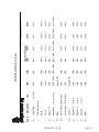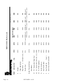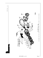
1
Price ® Pump Co.
INSTALLATION, OPERATING
AND MAINTENANCE MANUAL
TYPE CD CENTRIFUGAL PUMPS
MODELS: MS5050
PLEASE FILL IN FROM PUMP NAMEPLATE
Pump Model______________________
Spec. No._________________________
Serial No._________________________
Price ®
Pump Company
21775 8th. Street East
Sonoma, CA 95476
Tel: 707-938-8441
Fax 707-938-0764
Email: [email protected]
RETAIN MANUAL FOR REFERENCE
IN122-MS50 rev. B
Co ngratulations
You are now the ow ner of a Price® Pum p Co. Centrifugal Pum p. This pum p w a s care fully inspe cted and
subjected to fina l pe rform ance te sts be fore be ing rele ased for shipme nt. In orde r to achieve m axim um
perform ance a nd reliability, ple ase follow the simple instructions in this ma nual.
RECO M M EN DED P REC A U TION S
1 . For sa tis fa ct or y ope r at io n an d s afe ty , m a xim u m sys te m pr e ssur e m ust n ot e xce e d 3 5 0 ps i* (24 .6 k g/ sq cm ).
2 . For sa tis fa ct or y ope r at io n an d s afe ty , m a xim u m fluid te m pe ra tu re m us t not e xc ee d 3 0 0 ° F* (1 2 1 ° C).
3 . N o m odifica tion s, a dd itions or de let ions sh ould be m a de t o the pum p w it ho ut pr io r ap pr ova l o f t he fa ct ory .
4 . Dr a in p um p c om ple te ly an d flu sh w it h w a te r be for e se r vicin g a pum p ha ndling v olat ile or h ar m ful liquids .
R EAD CAR EFU LLY TH E CAU TIO N BELO W
The pe rformanc e of your Price® Pum p Co. Centrifuga l Pum p is base d on cle an, room tem perature , w ater w ith
suction conditions as show n on the pe rformance curve s. If used to pum p liquids othe r than w ater, pump
perform ance m ay differ from rated perform ance base d on the differe nt specific gravity, tem perature,
viscosity, e tc. of the liquid being pumped. A standard pump, how e ve r, may not be safe for pum ping all type s
of liquids, such as toxic, volatile or che mical liquids, or liquids under extre me te mpe ratures or pre ssures.
Please consult Price® Pum p Co. te chnical spe cifications as w ell as loca l code s and gene ral re fe re nces to
dete rm ine the appropriate pum p for your particular application. Since it is im possible for us to anticipate
eve ry application of a Price® Centrifugal pum p, if you plan to use the pump for a non-w ater application,
contact Price ® Pump Co. be forehand to dete rm ine w he the r such applic ation m ay be appropriate and safe
under the operating conditions. Failure to do so could re sult in property dam age or personal harm.
* De p e n d s o n se al m ate rials a n d se al typ e
Visit our w ebsite for product inform ation and technical support
w w w .pricepum p.com
Page - 2
IN122-MS50 rev. B
INSTALLATION / OPERATING INSTRUCTIONS
CENTRIFUGAL PUMPS
W a rn in g
C lo se C o u p le d M o to r P u m p s
Be fo r e in stallin g , re p a ir in g o r
It is su gge ste d th at th e se
p u m p s b e firm ly b o lte d to a
le v e l su rfac e . A d e q u at e air
p e rfo r m in g m a in t en a n c e o n
th is p u m p , re a d th ese
in stru ctio n s c o m p le te ly .
D isc o n n e c t p o w e r to p u m p
m o v e m e n t ar o u n d m o to r w ill
h e lp p re v e n t o v er h e at in g .
b e fo re se rv ic in g to av o id
d a n ge ro u s o r fa tal e lec tr ic al
D o n o t o v e r tig h te n in le t a n d
o u tlet p ip in g o r v o lut e m a y
sh o ck .
b e d am ag ed .
M a tc h s u p p ly v o lta ge an d
P o w er Fra m e M o u n t e d
P um ps
fre q u e n c y t o m o to r
n a m e p late v a lu es . In co rr ec t
v o lta ge c an ca u se fire o r
se rio u s m o to r d am ag e an d
v o id w ar ran ty .
G ro u n d m o to r b efo r e
c o n n e c tio n to e le c trica l
p o w er su p p ly ! Fa ilu re to
gr o u n d m o to r c an ca u se
se v e re o r fa tal e lec tr ic al
sh o ck !
D o n o t g ro u n d t o g a s su p p ly
lin e !
Be fo r e d isasse m b lin g p u m p ,
b e c e rta in a ll liq u id h a s b e e n
re m o v e d . If p u m p w as u se d
to p u m p h aza rd o u s o r to xic
flu id , it m u st b e
d e c o n ta m in ate d p rio r to
d isasse m b ly .
P o w e r Fram e m o u n te d
p u m p s m u st b e m o u n te d o n
a r ig id b as e th a t w ill n o t
w arp o r flex . E ac h p u m p
m u st b e m o u n te d su c h t h at
t h e p u m p sh aft ce n te r lin e is
in -lin e w ith th e d riv e r sh aft
c e n te rlin e. P a d s a n d /o r
sh im s w ill b e re q u ire d o n th e
p u m p , th e d riv er o r b o th to
in su r e p r o p e r alig n m e n t. Th e
t w o s h afts sh o u ld n o t to u c h
e a ch o th e r (e n d to e n d ) an d
t h e d ista n ce b et w ee n th e m
d e p e n d s o n th e co u p lin g
u s ed to co n n e ct th e m .
M isa lign m e n t w ill ca u se
v ib r atio n , b e arin g failu r e an d
v o id w ar ra n ty . P u m p s a re
r o u gh a lign e d at th e fa cto ry
IN122-MS50 rev. B
b u t m u s t b e re alig n e d a ft er
sh ip m e n t an d in sta llatio n .
P u lle y d r iv en p u m p m u st
h av e p u lle y s in lin e an d
p ro p er b elt tig h tn e ss
p ra ct ic e s fo llo w e d .
Dir e ct io n o f R o ta tio n
N o te : M o to r sh aft ro ta tio n is
v ie w e d fr o m th e s u ct io n e n d
o f p u m p . A ro tat io n a l ar ro w
is sh o w n o n th e fr o n t o f t h e
p u m p v o lu te ca sin g .
In co rre c t ro ta tio n c a n c au se
p u m p d a m a ge , failu re o r
re d u c e d p e r fo r m a n c e,
v o id in g w a rr an t y . It is b e st t o
ch e c k r o ta tio n b y
m o m e n tar ily e n e r giz in g o r
jo ggin g th e m o to r p rio r to
fillin g p u m p w ith liq u id .
W ar n in g ! D o n o t o p er ate
p u m p w ith o u t liq u id a s
d am ag e m a y r es u lt to th e
p u m p in te rn a l w e ar su r face s.
P lu m b in g
A ll p ip in g n e ed s to b e
su p p o r te d in d e p e n d e n t ly o f
th e p u m p . P ip in g
co n n e ct io n s sh o u ld n o t ex e rt
an y str ess o n th e p u m p
v o lu te o r fittin gs.
Page - 3
I N S TA L L AT I O N / O P E R AT I N G I N S T R U C T I O N S
Su ct io n P ip in g (In le t )
(H o rizo n t al P u m p s)
Su c tio n lin e m u st p ro v id e
ad eq u ate su ct io n p r es su re
an d e v e n (L am in a r) liq u id
flo w fo r p r o p e r p u m p
o p e r atio n . A ir , e n tr ap p e d in
th e su c tio n lin e d u e to le ak s
o r im p r o p e r p ip in g d e sign ,
m ay ca u se th e p u m p to lo se
p r im e. N o n -p r im in g p u m p s
m u st h av e t h e ir su c tio n
‘flo o d e d ’ a t st ar t u p (see
d a tash ee ts fo r m in im u m
N P SH R). A lso , th e s u ct io n
lin e m u st p r o v id e su ffic ie n t
p r ess u re (N P SH ) a n d ev e n
flo w to p u m p in le t to
p r ev e n t p u m p cav ita tio n .
T h e su c tio n p ip e en te rin g t h e
p u m p sh o u ld b e str aigh t an d
a m in im u m le n gth o f 5 tim e s
an d p r e fe r ab ly 1 0 tim e s th e
p u m p in le t d iam e te r. E lb o w s,
fit tin gs o r v alv es in stalled
c lo s e to th e p u m p in le t ca n
d isru p t liq u id flo w a n d c a u se
c av itat io n . Su ct io n lin e s
m u st b e at lea st th e sa m e
d iam et er a s t h e p u m p in let
o r lar ge r if p o ssib le .
P r ic e P u m p C o m p a n y
le ak s re su ltin g fr o m w e ar o r
fo u lin g. Su ct io n p ip in g m u st
b e d e sig n e d to p r ev en t v a p o r
fro m b e in g tr ap p ed in h igh
sp o ts in th e p ip in g. T h is
c o n d itio n m a y c au se th e
p u m p to v ap o r lo c k .
D isc h a rg e P ip in g (O u t le t )
T o co n tro l flo w an d
d isc h ar ge h ea d , it is
a d v isab le to in sta ll a v a lv e
(glo b e , b all, o r o th e r
a d ju sta b le an d n o n -lea k
t y p e ) in th e d isc h a rge lin e
a d jac e n t t o t h e p u m p . T h e
v a lv e m a y b e clo se d d u rin g
sy ste m r e p airs to p re v e n t
b a c k flo w . By in s tallin g a
c h e ck v a lv e in th e d isc h ar ge
lin e, b ac k flo w c an also b e
p r e v e n te d d u rin g
m ain te n a n ce o r d u rin g
p e r io d s o f p u m p sto p p ag e.
O p e r at io n
A ll c en trifu gal p u m p s m u st
b e fille d w it h liq u id p rio r to
st ar t u p . It is s u gge ste d th at
d u rin g in itial st art u p th e
d isc h ar ge v alv e b e c lo s ed
a n d th e n o p e n e d a s th e
m o to r r e ac h es fu ll rp m ’s. If
N o t e : A c e n trifu ga l p u m p s
flo w ra te a n d h ea d
(p re ssu r e) w ill v ar y w ith th e
am o u n t o f r e sista n c e (p ip e
fr ic tio n an d flo w r est rictio n s)
in th e d isc h a rge lin e . A s th e
v alv e o n th e d isc h a rge lin e
o p e n s, t h e flo w r ate an d
m o t o r am p er e s d r aw w ill
in c re a se a n d h e a d (p r essu re )
w ill d e c re ase . A s th e v alv e o n
th e d isc h ar ge lin e is c lo se d ,
th e flo w rat e an d a m p e re s
d ra w w ill d e cr ea se a n d t h e
h e ad (p re ssu r e) w ill in cr ea se .
If re sista n ce in th e d isc h ar ge
lin e is n o t su fficie n t, th e
p u m p w ill o p e ra te at a
co n d it io n o f m ax im u m flo w ,
so m e tim e s ca lle d " en d o f
cu r v e " p er fo rm an c e.
M a xim u m h o rse -p o w e r is
re q u ire d to o p e ra te at th is
p o in t an d m o t o r o v e rlo ad
m a y r esu lt. If e xc e ssiv e
am p e re s d r aw an d m o to r
o v e rlo ad is o c c u rr in g , re d u c e
th e s ys tem flo w rat e b y
in st allin g a v alv e o r o rifice in
th e d isc h ar ge lin e to co n tro l
(r e strict ) th e p u m p s flo w
ra te . A lter n at iv e ly , re d u ce
p u m p h e a d b y tr im m in g
re c o m m e n d s aga in st u s in g
fo o t v alv e s in th e su c tio n lin e
to m a in tain liq u id in th e
p u m p w h e n it’s n o t
o p e r atin g. If fo o t v alv e s a re
p u m p d o e s n o t b u ild u p
p r e ssu re as m o t o r sp e ed
in c re ase s, sh u t d o w n an d
im p e lle r t o a sm alle r
d ia m e te r.
m ak e su re t h at liq u id flo w
in to p u m p is n o t re str ic te d
u se d , d u e to su c tio n lift
c o n d itio n s, t h ey m u st be
(se e “ Tr o u b le sh o o tin g” ).
C o n s u lt P ric e P u m p o r a lo ca l
P rice P u m p d istrib u to r fo r
assista n ce .
w w w .ap p sup po r t@ p ric ep um p.c o m
p r o p e rly m ain ta in e d to av o id
Page - 4
IN122-MS50 rev. B
TROUBLESHOOTING
1 . P u m p fails to b u ild h e a d
p r e ssu re :
3 . E xce ssiv e n o is e o r
v ib r atio n d u r in g o p e r at io n .
5 . P u m p g ra d u ally lo se s
p r es su r e a n d h e a d .
C h e c k fo r :
C h e ck fo r:
C h e c k fo r:
a. P u m p n o t p r im e d .
a . M o to r b e a rin g fa ilin g.
a. In cr ea sin g tem p e ra tu re
b . In co rre c t p u m p ro tatio n .
b . P u m p c av ita tio n .
ca u sin g ca v it atio n o r liq u id
v ap o rizatio n .
c . D riv er s p ee d to o lo w .
c . Im p ro p er im p elle r
c le a ra n ce .
b . D riv e r fa ilu r e.
d . Su ct io n lin e re str ic te d .
c. Su c tio n lift to o h igh .
e . D riv e r fa ilu re .
f. P lu gg ed o r d a m a ge d
im p e lle r.
g. P u m p o r im p e lle r
u n d e r size d .
h . P u m p c av itatio n .
i. Im p ro p e r im p e lle r
c le ar an c e .
2 . P u m p fails to p r o vid e
e n o u gh flo w r a te .
C h e c k fo r :
a. Sy st em r esista n ce to o
h igh .
b . P u m p u n d er size d .
c . P u m p n o t p rim e d .
4 . L ea kin g m e c h a n ica l se a l.
d . A ir e n te rin g su ct io n lin e .
C h e ck fo r:
a . Im p ro p er a sse m b ly .
b . W o r n o r c ra ck e d se al
fa ce s.
c . A b ras iv e m ate r ia l in flu id .
d . L iq u id flash in g a t s ea l
fa ce s (Flu id t em p e ra tu re to o
h igh ).
e . Se al p r essu re r atin g to o
lo w fo r th e se r v ic e.
f. C h e m ica l at tac k o f se al
c o m p o n e n ts.
6 . M o t o r o v e rh e a tin g .
C h e c k fo r:
a. Ex c essiv e flo w a n d am p
d ra w (T h ro t tle d is ch a rge ).
b . L o w v o ltage o r fre q u e n cy .
c. Flo w r ate to o lo w w ith
re su ltin g h ea t rise.
d . B e arin g failu r e .
e. Sy ste m te m p er atu re to o
h ig h .
g . Se al o p e ra te d d r y o r w ith a
liq u id h a v in g p o o r lu b rica tin g
p r o p e r tie s.
d . D r iv e r sp e e d to o lo w .
e . P o o r su c tio n c o n d itio n s.
f. Im p ro pe r im p e lle r
c le ar an c e .
IN122-MS50 rev. B
Page - 5
R E PA I R A N D M A I N T E N A N C E
Before attempting any repairs under warranty, contact Price Pump to obtain factory authorization.
Repairs carried out without authorization may void warr anty. Many causes of pump failure are due to
improper system design. Refer to the trouble shooting lis t in this manual before carrying out pump
inspection or repair.
DISASSEMBLY
1. Disconnect power source
to motor.
2. Disconnect electrical
connections tagging wires
carefully to preserve correct
rotation. Loosen motor base.
3. Remove pump and motor
assembly. Observe position
of all parts prior to
disassembly.
4. Remove stage connector
bolts.
5. Remove suction plate.
6. Loosen impeller setscrews
and remove impeller by
sliding off pump shaft.
7. Slide diffuser off of pump
shaft.
8. Remove stage separa tor
and O-ring.
9. Repeat steps 5 through 7
until last impeller is removed
from the pump shaft.
10. Remove seal head from
pump. Type 21: Slide seal
head from the shaft. Type 9:
Loosen set screws and slide
seal head off shaft.
11. Remove four motor bolts
and remove bracket from
motor.
Page - 6
12. Remove seal seat from
bracket. Use wooden or
plastic dowel to tamp the
seat from the bracket.
REASSEMBLY
1. Clean seat cavity of the
bracket thoroughly.
2. Thoroughly clean pump
shaft. Assure that the shaft i s
not grooved and that there is
no evidence of pitting or
fretting. Polish the shaft with
extra fine emery cloth and
clean the keyway. If the shaft
is grooved, fretted or worn,
replace it.
To help ensure the seat is
not damaged place the
cardboard disk supplied with
the seal over the seat face.
Gently tap seat into place
with a wooden dowel or a
plastic rod (1-1/8" outside
diameter).
5. Place bracket on motor
(aligning the base if
applicable). Secure bracket
with four mo tor bolts.
6. Pull pump shaft forward
until shoulder of pump shaft
contacts back of bracket and
slightly snug one s etscrew to
hold shaft in place.
3. Install the pump shaft
onto the motor shaft,
aligning set screws of the
pump shaft with the keyway
of the motor shaft. Ensure all
debris and burrs are
removed from the motor
shaft and that the slinger is
in place, midway between
the setscrews.
7. Install seal head assembly
4. For Type 21, 8, 9 seals:
Place the bracket on a firm
surface with the sea t cavity
(pump end) up. Then place a
small amount of vegetable
oil on the seat cup or "O"
ring seat. Place the seat in
the seat cavity with the
polished face up toward the
pump end. Evenly push seat
into cavity with fingers.
c. Install seal spring and
retainer.
IN122-MS50 rev. B
For Type 21 Seals:
a. Lubricate shaft and
elastomer with vegetable oil.
b. Install rotary seal head
onto pump shaft and slide
toward seat until carbon face
touches ceramic seat.
d. Install impeller. Slide
impeller onto shaft until
impeller hub bottoms out on
the shoulder of the shaf t.
Tighten impeller setscrews
securely.
R E PA I R A N D M A I N T E N A N C E
REASSEMBLY (cont.)
Note: Ensure that the spring
retainer does not slip
between the shoulder of the
shaft and the hub of the
impeller.
e. Install new volute O -ring
and mount volute (lightly
coat O-ring with vegetable
oil). Secure with bolts and
tighten.
f. Loosen pump shaft
setscrew and install stage
separator with chamfer side
towards impeller. Push stage
separator until it bottoms
out on the flange.
Note: For 1 stage pumps
there is no stage separator.
Install the suction plate and
set impeller.
g. While pressure is applied
to stage separator slightly
snug one pump shaft
setscrew at this time to hold
the pump shaft in place.
h. Install O -ring on diffuser
and lightly coat O -ring with
vegetable oil. Install diffuser
with O-ring onto the volute
case. When installing
diffuser apply even pressure
to avoid damaging carbon
bushing.
i. Install next stage
impeller; do not tighten
impeller setscrews at this
time.
j. Install setting plate and
tighten bolts.
k. Pull impeller forward
with setscr ew wrench
provided in assembly kit until
impeller touches the setting
plate. Tighten impeller
setscrews.
l. Remove setting plate.
Install next stage separator
and diffuser with O -ring.
m. Install the next stage
impeller; do not tighten
impeller set screws at this
time.
n. Install setting plate and
tighten bolts.
o. Pull impeller forward
with setscrew wrench
provided in assembly kit until
impeller touches the setting
plate. Tighten impeller
setscrews.
p. Remove setting plate
and repeat steps l. through
o. for additional stages.
q. After last impeller is set,
remove setting plate and
install suction plate and
tighten bolts.
8. Set impeller clearance
with setting tool. Turn
setting tool approximately
1/2-3/4 of a turn. Proceed to
step 10.
For Type 8 & 9 Seals:
IN122-MS50 rev. B
a. Install impeller. Slide
impeller onto shaft until
impeller hub bottoms out on
the shoulder of the shaft.
Snug impeller setscrews.
b. Install new volute O -ring
and mount volute (lightly
coat O-ring with vegetable
oil). Secure with bolts and
tighten.
c. Loosen pump shaft
setscrew and install stage
separator with chamfer side
towards impeller. Push stage
separator until it bottoms
out on the flange.
Note: For 1 stage pumps
there is no stage separator.
Install the setting plate and
set impeller.
d. While pressure is applied
to stage separator slightly
snug one pump shaft
setscrew at this time to hold
the pump shaft in place.
e. Remove stage separator
and impeller. Install seal.
Install Seal: Type -9
f. Do not rem ove metal
clips from seal head. Install
seal head onto pump shaft
sliding gently past shoulder
of shaft. Slide seal head
toward seat until carbon face
contacts ceramic seat.
Tighten seal head setscrews
to pump shaft using short
arm Allen wrench supplied
with seal or repair kit.
Remove clips in seal head
and discard.
Page - 7
R E PA I R A N D M A I N T E N A N C E
REASSEMBLY (cont.)
Type-8
Compress seal to a distance
of 3/4” from, the front side
of seat face, to the backside
of seal casing. (do not
measure from bore face of
bracket). Tighten seal head
set screws
g. Reinstall impeller
(tighten setscrews securely ).
h. Reinstall stage separator.
i. Install O -ring on diffuser
and lightly coat O -ring with
vegetable oil. Install diffuser
with O-ring onto the volute
case. When installing
diffuser apply even pressure
to avoid damaging carbon
bushing.
j. Install next stage
impeller, do not tighten
impeller setscrews at this
time.
k. Install setting plate and
tighten bolts.
l. Pull impeller forward with
setscrew wrench provided in
assembly kit until impeller
touches the setting plate.
Tighten impeller sets crews.
m. Remove setting plate.
Install next stage separator
and diffuser with O -ring.
n. Install next stage
impeller; do not tighten
impeller setscrews at this
time.
Page - 8
o. Install setting plate and
tighten bolts.
thoroughly, making sure all
air is purged.
p. Pull impeller forward
with setscrew wrench
provided in assembly kit until
impeller touches the setting
plate. Tighten impeller
setscrews.
14. Start pump allowing
adequate time to purge all
air from system. Observe any
gauges, flow meters, e tc. to
see of pump performs
properly.
q. Remove setting plate
and repeat steps m. through
p. for additional stages.
r. After last impeller is set,
remove setting plate and
install suction plate and
tighten bolts.
9. Set impeller clearance
with setting tool. Turn
setting tool approximately
1/2-3/4 of a turn. Proceed to
step 10.
10. Rotate pump shaft by
hand to ensure impeller does
not rub against volute.
11. Return pump to
installation, reconnect
electric connections.
12. Start pump momentarily
to observe shaft rotation. If
rotation corresponds the
rotation arrow pump may be
put into service. If rotation is
incorrect, switch any two
leads on 3-phase motors.
Check wiring diagram of
motor for single phase
rotation.
13.Remove top pipe plug (if
applicable) from the front of
volute and prime pump
IN122-MS50 rev. B
R E PA I R A N D M A I N T E N A N C E
INSTALLING A PEO (PUMP END ONLY) STUB SHAFT PUMP
a. Place the bracket on a firm surface, loosen stub shaft setscrews and carefully remove shipping
plug.
b. Place motor in an upright position with motor shaft pointing upward. Make sure motor shaft and
end bell flange are free of burrs and surfaces are clean.
c. Align PEO stub shaft setscrews (if applicable) with motor shaft keyway and carefully slid the PEO
onto the motor shaft until it sits firmly onto the motor end bell flange.
d. Oriented the PEO’s discharge port or base to preferred motor configuration while referencing the
motors electrical box position.
e. Install flange bolts and tighten. (Install pump base if applicable)
f.
Reposition pump back onto motor base.
g. Refer to pump Reassembly Instructions and proceed to setting the impeller clearance
(if applicable).
INSTALLING A PEO (PUMP END ONLY) NON-STUB SHAFT PUMP
a. Carefully un -pack all components received with your shipment and remove any shipping plugs.
b. Place the bracket on a firm surface with the s eat cavity (pump end) up. Follow seal Installation /
reassembly instructions contained within this manual.
c. Make sure motor shaft and motor end bell flange are free of burrs and surfaces are clean.
d. Carefully place the Bracket assembly over the motor shaft and align bracket with motor end bell
flange.
e. Install impeller, gasket or o -ring, volute and volute mounting bolts.
f.
Oriented the PEO’s discharge port or base to preferred motor configuration while referencing
the motors electrical box position.
g. Install motor flange bolts and tighten all bolts to proper torque . (Install pump base if applicable)
IN122-MS50 rev. B
Page - 9
R E PA I R A N D M A I N T E N A N C E
Type 21 C Face Style Double Seal Installation
(For Type CD, RC, LT & MS Series Pumps )
Double Seal pumps are generally used for one of these reasons:
1.
To avoid seal damage when pumping abrasives.
2.
To manage seal temperature when pumping hot liquids.
3.
To prevent pump fluid from leaking to atmosphere when pumping toxic or other hazardous liquids.
A double seal must have pressure to the seal chamber at a minimum of 5 PSI preferable 10 PSI above
pump pressure.
Flow rate through seal chamber will depend upo n pump fluid temperature. Minimum flow rate should be
1 GPM for CD, RC, LT & MS Series Pumps . Flow rates may have to be increased with higher temperatures.
Check the seal chamber discharge fluid temperature to be sure fluid is below boiling . We suggest a 140°F
to 150°F temperature range. If seal cooling liquid flashes, seal may be come damaged. Seal chamber fluid
should enter at the bottom and discharge at the top to avoid entrapped air in the chamber. Be sure to
prime the secondary pumping system pro perly as you would any other system.
CAUTION: Always Pressurize the Seal Chamber before starting the main pump!
In a pumping system that st arts and stops automatically, in sure that both pumps start at the same time.
REASSEMBLY:
1. Clean seat cavity of t he
bracket and seal plate
thoroughly.
2. Thoroughly clean pump
shaft. Assure that the shaft
is not grooved and that
there is no evidence of
pitting or fretting. Polish the
shaft with extra fine emery
cloth and clean the keyway.
If the shaft is grooved,
fretted or worn, replace it.
3. Install the pump shaft
onto the motor shaft,
aligning set screws of the
pump shaft with the keyway
Page - 10
of the motor shaft. Ensure
all debris and burrs are
removed from the motor
shaft and that the slinger is
in place.
5. Pull out pump shaft as far
as it will go toward volute
end and slightly tighten one
set screw to hold shaft in
place
on the seat cup. Install
seats into seat plate and
bracket with polished faces
up. Evenly push seat into
seat cavity with fingers,
then gently tap seat into
place with a wooden dowel
or plastic rod (1 -1/8"
outside diameter). To help
ensure the se at is not
damaged, place the
cardboard disk supplied
with the seal under the end
of the dowel to prevent
damaging the seat face.
6. Place a small amount of
vegetable oil (or equivalent)
7. Install seal head
assembly:
4. Place brac ket on motor
(aligning the base if
applicable). Secure bracket
with four motor bolts.
IN122-MS50 rev. B
R E PA I R A N D M A I N T E N A N C E
For Type 21:
a. Lubricate shaft and
elastomer with vegetable oil
or equivalent.
c. Install impeller washer
and lockdown. Tighten to 10
ft-lbs.
b. Install first rotary seal
head onto pump shaft and
slide toward seat using a
twisting motion until carbon
face touches seal seat.
10. Loosen pump shaft set
screw.
c. Install second rotary seal
head onto s haft sleeve with
carbon facing towards
pump end.
8. Install seal plate onto
pump end of bracket with
new gasket and tighten cap
screws evenly (note: u se
pipe sealant on bolts).
9. Install impeller:
a. Install key in pump shaft.
b. Slide impeller onto shaf t.
11. Install new volute gasket
or o-ring and mount volute.
Secure with bolts and
tighten evenly.
12. Move shaft back with a
screwdriver .010”-.015”.
Tighten pump shaft set
screws. Turn shaft by hand
to ensure impeller does not
rub against volute.
13. Return pump to
installation, reconnect
electric connections.
14. Start pump momentarily
to observe shaft rotation. If
rotation corresponds to the
rotation arrow on the
pump, it may be put into
service. If rotation is
incorrect, switch any two
leads on 3-phase motors to
change rotation. Check
wiring diagram of motor for
single phase rotation
correction.
15. Remove top pipe plug (if
applicable) from the front of
volute and prime pump
thoroughly, making sure all
air is purged. Turn shaft
one revolution and then
refill. Replace the pipe plug.
16. Start pump allowing
adequate time to purge all
air from system. Observe
any gauges, flow meters,
etc., to see if pump
performs properly.
Double Seal Flush Piping Installation
1. Piping of the double seal
arrangement should be
done in accordance with all
governmental regulations
and safety codes.
2. All double seals require a
barrier flush between the
seals for proper lub rication
and cooling. The barrier
liquid must be maintained
at 10-15 PSIG above the
discharge pressure of the
pump and it must be
chemically compatible with
the pumped liquid, material
construction of the pump,
and seals (5/8" double seals
have 18-8 parts).
3. The barrier flush shall
have a minimum flow rate
in accordance with the
graph below. If water is
used as a fluid, the inlet
temperature should not
exceed 140 °F.
4. A positive pressure must
be maintained to the barrier
flush between the seal face s
even when the pump is not
running. To conserve the
barrier liquid a solenoid
IN122-MS50 rev. B
valve (Item 1) may be
installed and connected
electrically in parallel with
the motor so the barrier
fluid flows only when the
pump is running. Note: The
maximum pressure of the
barrier fluid at the inlet is
150 PSIG.
5. The inlet should be
connected to the bottom
and the outlet to t he top of
the seal cavity.
Page - 11
R E PA I R A N D M A I N T E N A N C E
Procedures f or Checking Double Seals for Internal Leakage
Option 1 - for use with 2 flow meters.
Install flow meters on the inlet and outlet lines. Normal operating conditions will be indicated by equal
or near equal flow on both flow meters. If the inl et flow meter shows more flow than the outlet, this
could indicate excessive leakage.
Option 2 - for use with 1 flow meter.
1. Shut off flow at outlet needle valve (Item 2).
2. Shut off inlet gate valve (Item 8) - for 15 seconds maximum.
3. If pressure in seal cavity drops rapidly rather than gradually while the gate valve is shut, the seal is
leaking excessively.
4. To restart open gate valve first then reset valve on outlet.
Page - 12
IN122-MS50 rev. B
THIS PAGE INTENTIONALLY LEFT BLANK
IN122-MS50 rev. B
Page - 13
Page - 14
IN122-MS50 rev. B
F.
(1 - # of stages req’d.)
GFT
Volute
(1 - # of stages req’d.)
Graphite
Bushing(s):
E.
3000
3076
N/A
3000
3075
3020-1
N/A
N/A
3073
(1 + # of stages req’d.) 3073
EPR
(1 - # of stages req’d.)
3072
(1 + # of stages req’d.) 3072
Neoprene
Diffuser
3071
(1 + # of stages req’d.) 3071
PTFE
D.
3070
3080
3040-4.12
3040-4.12
3080
3010
2MS
3010
1MS
Fluorocarbon (1 + # of stages req’d.) 3070
O Rings (Diffuser/Volute)
(2 req’d. per stage)
Setscrews
C.
(1 req’d. per stage)
Impeller(s)
B.
Qty.
Suction Plate
Description
A.
Key #
3000
3076
3075
3020-1
3073
3072
3071
3070
3080
3040-4.12
3010
3000
3076
3075
3020-1
3073
3072
3071
3070
3080
3040-4.12
3010
Number of Stages
3MS
4MS
MS50 SS Parts List
3000
3076
3075
3020-1
3073
3072
3071
3070
3080
3040-4.12
3010
5MS
3000
3076
3075
3020-1
3073
3072
3071
3070
3080
3040-4.12
3010
6MS
MS50 plist.doc rev. B
IN122-MS50 rev. B
Page - 15
Base
0199
0199
3081
R.
(4 req’d.)
3081
Washers
Q.
3082
3084
5501
5478
3082
Stage Nuts
P.
(4 req’d.)
3083
Stage Bolts
N.
(4 req’d.)
Specify P/N
5501
Power Frame 7/8” ID Shaft
M3. Air Motor
5478
M2. Power Frame 5/8” ID Shaft
0673 / 0593
0673 / 0593
Specify P/N
Motor Bolts
L.
0522
3133-1
3055-1
0917
2MS
0522
3132-1
3050-1
0917
1MS
M1. Motor
Slinger, 7/8"
K.
7/8" ID
(8 req’d.)
Qty.
(2 of ea. req’d.)
Shaft w/setscrews:
J.
5/8" ID
Volute Bolts
Description
G.
Key #
0199
3081
3082
3085
5501
5478
0673 / 0593
0522
3134-1
3060-1
0917
0199
3081
3082
3086
5501
5478
0673 / 0593
0522
3135-1
3065-1
0917
Number of Stages
3MS
4MS
MS50 SS Parts List
0199
3081
3082
3087
5501
5478
0673 / 0593
0522
3136-1
3066-1
0917
5MS
0199
3081
3082
3088
5501
5478
0673 / 0593
0522
3137-1
3067-1
0917
6MS
MS50 plist.doc rev. B
Page - 16
IN122-MS50 rev. B
0985
U2. T.21 Fluorocarbon Dbl Seal
Quench Lip Seal Fluorocarbon
Y.
0891
0891
0256
0256
Seal Cover Bolts
X.
(3 req’d.)
Seal Cover Gasket
V.
0973
1150
0985
0553
N/A
0974
0973
Double Seal Cover
W.
3030
0972
3030
0972
Number of Stages
3MS
4MS
3030
0972
5MS
3030
0972
6MS
MS50 plist.doc rev. B
0891
0256
0974
0973
1150
0985
0553
N/A
0891
0256
0974
0973
1150
0985
0553
N/A
0891
0256
0974
0973
1150
0985
0553
N/A
0891
0256
0974
0973
1150
0985
0553
N/A
3030-1(1 req’d.) 3030 (1 req’d.) 3030 (2 req’d.) 3030 (3 req’d.) 3030 (4 req’d.)
3030-(1 req’d.) 3030-1(1 req’d.) 3030-1(1 req’d.) 3030-1(1 req’d.)
3030
0972
2MS
0974
1150
U3. T.9 PTFE Single Seal
(2 req’d.)
0553
3010-1
N/A
N/A
0972
1MS
U1. T.21 Fluorocarbon Single Seal
Seal w/Seat:
Suction Plate for Dbl Seal
Double Seal
Qty.
(1 - # of stages req’d.)
Stage separator(s):
T.
Single Seal
Bracket
Description
S.
Key #
MS50 SS Parts List
IN122-MS50 rev. B
Page - 17
21775 Eighth Street East * Sonoma, CA 95476-0329 * (707) 938-8441 * Fax (707) 938-0764
MS50_P.dwg
rev. A
PRICE CENTRIFUGAL PUMP CAUTIONS & WARNINGS
•
•
•
•
•
•
•
•
•
CAUTION: Price Pump centrifugal pumps must be operated above mi nimum flow rate to avoid damage .
CAUTION: All Price Pump centrifugal pumps require the suction to be flooded .
CAUTION: It is recommended that a ll piping connections to the pump be flexible.
WARNNING: Verify chemical compatibility of the pump materials of construction with the flui d being pumped.
WARNNING: Price centrifugal pumps are not designed for use in sanitary or food applications.
CAUTION: Use only Price Pump original equipment factory replacement parts.
WARNNING: Price pump fluid temperature limits must be observed. Maximum operating temperature is 300 °F.
CAUTION: The pump should be thoroughly flushed and drained before disassembly.
CAUTION: For larger pump motor units, weight may exceed 65 1bs. (30 kg).
CAUTION: Maximum working pressure for seals:
o
o
o
o
o
o
Type 6 Seal
Type 6A Seal
Type 8 Seal
Type 9 Seal
Type 21 Seal
Type 2106 Seal
75 PSI (5.2 bar)
75 PSI (5.2 bar)
325 PSI (22.4 bar)
350 PSI (24.1 bar)
150 PSI (10.3 bar)
150 PSI (10.3 bar)
CAUTION: Maximum solid size by pump
o
o
o
o
o
o
o
o
o
o
o
o
o
o
o
HP75 / MS50
SP150
LT25
F50/75/95
OH75
CD100/150
CL150
RC200/300
XJ-JB100
XJ-JB150
XJ-JB200
XJ400
XL-XT100
XL-XT150
XL-XT200
Page - 18
0.030” (0.76mm)
0.060” (1.50mm)
0.120” (3.05mm)
0.150” (3.81mm)
0.150” (3.81mm)
0.150” (3.81mm)
0.150” (3.81mm)
0.380” (9.60mm)
0.120” (3.05mm)
0.250” (6.40mm)
0.440” (11.2mm)
0.440” (11.2mm)
0.120” (3.05mm)
0.250” (6.40mm)
0.440” (11.2mm)
CAUTION: Minimum flow rate by pump
o
o
o
o
o
o
o
o
o
o
o
o
o
o
o
o
o
HP75 / MS50
SP150
LT25
F50/75/95
OH75
CD100
CD150
CL150
RC200
RC300
XJ-JB150
XJ-JB150
XJ-JB200
XJ400
XL-XT100
XL-XT150
XL-XT200
IN122-MS50 rev. B
0.5 GPM (1.9 LPM)
10 GPM (38 LPM)
0.5 GPM (1.9 LPM)
5.0 GPM (19 LPM)
7.0 GPM (26 LPM)
12 GPM (45 LPM)
25 GPM (94 LPM)
40 GPM (150 LPM)
10 GPM (38 LPM)
50 GPM (189 LPM)
20 GPM (75 LPM)
40 GPM (150 LPM)
90 GPM (340 LPM)
100 GPM (378 LPM)
10 GPM (38 LPM)
35 GPM (132 LPM)
50 GPM (189 LPM)
GENERAL TERMS OF SALE
1. GENERAL
A. Seller's price is based on these sales terms and conditions. The agreement and inclusion of other
or amended terms in this contract will result in a change (including increase) in Seller's price (as may
be contained in any price books or quotations) to reflect such other or amended terms. This contract
shall represent the final, complete and exclusive statement of the agreement between the parties
and may not be modified, supplemented, explained or waived by parole evidence, any Terms and
Conditions contained in Buyer's purchase order or request for quotation, any course of dealings
between the parties, Seller's performance or delivery, or in any other way. The Terms and
Conditions of this contract may only be modified or waived in a written document signed by an
Officer of Seller. These terms are intended to cover all activity of Seller and Buyer hereunder,
including sales and use of products, parts and work and all related matters (references to products
include parts and references to work include construction, installation and start-up). Any reference
by Seller to Buyer's specifications and similar requirements are only to describe the products and
work covered hereby and no warranties or other terms therein shall have any force of effect. Any
information provided by Seller including, but not limited to, suggestions as to specific equipment
does not imply any guarantee of specific suitability and/or material compatibility in a particular
application, since many factors outside the control of Seller may affect the suitability of products in a
particular application. Catalogs, circulars, similar pamphlets and information contained on websites
of the Seller are issued for general information purposes only and shall not be deemed to modify the
provisions hereof.
B. The agreement formed hereby and the language herein shall be construed and enforced
under the Uniform Commercial Code as in effect in the State of California on the date hereof.
2. TAXES
Any sales, use or other similar type taxes imposed on this sale or on this transaction and/or any
import or export duties or fees as may be assessed or imposed on or as a result of deliveries under
this transaction are not included in the price. Such taxes shall be billed separately to the Buyer.
Seller will accept a valid exemption certificate from the Buyer if applicable; however, if an exemption
certificate previously accepted is not recognized by the governmental taxing authority involved and
the Seller is required to pay the tax covered by such exemption certificate. Buyer agrees to promptly
reimburse Seller for the taxes paid.
3. PERFORMANCE, INSPECTION AND ACCEPTANCE
A. Unless Seller specifically assumes installation, construction or start-up responsibility, all products
shall be finally inspected and accepted within thirty (30) days after arrival at point of delivery. Where
seller has responsibility for installation, construction or start-up all work shall be finally inspected and
accepted with thirty (30) days after completion of the applicable work by Seller. All claims
whatsoever by Buyer, (including claims for shortages) except only those provided for under the
WARRANTY AND LIMITATION OF LIABILITY and PATENTS Clauses, hereof, must be asserted in
writing by Buyer within said thirty (30) day period or they are waived. If this contract involves partial
performance, all such claims must be asserted within said thirty- (30) day period for each partial
performance. There shall be no revocation of acceptance. Rejection may be only for defects
substantially impairing the value of products or work and Buyer's remedy for lesser defects shall be
those provided for under the WARRANTY AND LIMITATION OF LIABILITY Clause.
B. Seller shall not be responsible for non-performance or for delays in performance occasioned by
any causes beyond Seller's reasonable control, including, by way of example and not limitation, to
labor difficulties, delays of vendors or carriers, fires, governmental actions, or shortages of material,
components, labor, or manufacturing facilities. Any delays so occasioned shall affect a
corresponding extension of Seller's performance dates, which are, in any event, understood to be
approximate. IN NO EVENT SHALL BUYER BE ENTITLED TO INCIDENTAL OR
CONSEQUENTIAL DAMAGES FOR LATE PERFORMANCE OR FOR A FAILURE TO PERFORM.
Seller reserves the right to make partial shipments and to ship products, parts or work which may be
completed prior to the scheduled performance date.
C. In the event that Seller has agreed to mount motors, turbines, gears, or other products which are
not manufactured by Seller and which are not an integral part of Seller's manufactured product, and
a delay in the delivery of such products to Seller occurs that will cause a delay in Seller's
performance date, Seller reserves the right to ship its product upon completion of manufacture and
to refund an equitable portion of the amount originally included in the purchase price for mounting
without incurring liability for non-performance.
D. Seller reserves to itself the right to change its specifications, drawings and standards if such
changes will not impair the performance of its products, and parts, and further those products, and
parts, will meet any of Buyer's specifications and other specific product requirements which are a
part of this agreement. Seller is a global supplier of products and utilizes parts and products
obtained worldwide, and Seller's products supplied under this contract shall be subject to Seller's
sole determination as to all manufacturing, sourcing, assembly and supply unless otherwise
specifically agreed in writing.
E. The manufacture and inspection of products and parts shall be to Seller's Engineering and
Quality Assurance standards, plus such other inspections or tests of documentation as are
specifically agreed to by Seller. Requirements for any additional inspection, tests, documentation, or
Buyer witness of manufacture, test, and/or inspection shall be subject to additional charges.
4. TITLE AND RISK OF LOSS
Title and risk of loss shall pass to buyer upon delivery of products at the designated "Ex Works" as
defined by Incoterms, unless other wise agreed by the parties.
5. EROSION AND CORROSION
It is specifically understood that products and parts sold hereunder are not warranted for
operation with erosive or corrosive fluids or for operation with any fluid or under any operating
condition in variance with the specifications of this contract. No product or part shall be deemed
to be defective by reason of failure to resist erosive or corrosive action of any fluid and Buyer
shall have no claim whatsoever against Seller therefore. No product shall be deemed defective
by reason of any effect on Seller's products of the action or results (such as vibration) of any
goods or system (such as piping) not supplied by Seller.
Effective June 2007
6. BUYER’S RESPONSIBILITY
The design specifications of the equipment require the operation of the equipment within certain
parameters and may call for the use of speed controls, safety devices, set points or other control
devices to insure that the operation remains within design parameters. Buyer agrees and understands
that the equipment must be operated and maintained within design specifications and operated within
the specifications of the contract, irrespective of whether controls or devices are otherwise required.
7. WARRANTY AND LIMITATION OF LIABILITY.
A. Seller warrants only that its product and parts, when shipped, will be free from defects in materials
and workmanship. All claims for defective products or parts under this warranty must be made in writing
immediately upon discovery and, in any event, within two (2) years of shipment by seller and all claims
for defective work must be made in writing immediately upon discovery. Defective items must be held
for Seller's inspection and returned to the sellers’ point of original shipment upon request.
ANY UNAUTHORIZED DISSASSEMBLY, ALTERATION OF OR TAMPERING WITH ANY PRODUCT
OR COMPONENT MAY "VOID" THE WARRANTY, IN THAT SUCH ACTION WILL RESULT IN
SELLER BEING RELEASED AND RELIEVED FROM ITS OBLIGATIONS UNDER THIS WARRANTY
AND FOR ANY FURTHER COSTS OR ACTIONS UNDER CLAUSE 7.C, FOLLOWING, AND THE
BUYER ASSUMING SOLE RESPONSIBILITY FOR THE COSTS AND RESULTS OF SUCH ACTION.
THE FOREGOING IS EXPRESSLY IN LIEU OF ALL OTHER WARRANTIES WHATSOEVER,
EXPRESS, IMPLIED AND STATUTORY, INCLUDING WITHOUT LIMITATION, THE IMPLIED,
WARRANTIES OF MERCHANTABILITY AND FITNESS.
B. ANY PRODUCT (S) SOLD HEREUNDER WHICH ARE NOT MANUFACTURED BY SELLER ARE
NOT WARRANTED BY SELLER and shall be covered only by the express warranty, if any, of the
manufacturer thereof. With respect to products and parts not manufactured by Seller, Seller's only
obligation shall be to assign to Buyer, to the extent possible, whatever warranty Seller obtains from the
manufacturer.
C. Upon Buyer's submission of a claim as provided above and its substantiation, Seller shall at its
option either (i) repair or replace its product, part or work at the original place of shipment, or (ii) refund
an equitable portion of the purchase price.
D. THE FOREGOING IS SELLER'S ONLY OBLIGATION AND BUYER'S EXCLUSIVE REMEDY FOR
BREACH OF WARRANTY AND, EXCEPT FOR THE REMEDIES PERMITTED UNDER THE
PERFORMANCE, INSPECTION AND ACCEPTANCE AND THE PATENTS CLAUSES HEREOF, THE
FOREGOING IS BUYER EXCLUSIVE REMEDY AGAINST SELLER FOR ALL CLAIMS ARISING
HEREUNDER OR RELATING HERETO WHETHER SUCH CLAIMS ARE BASED ON BREACH OF
CONTRACT, TORT (INCLUDING NEGLIGENCE OR STRICT LIABILITY), INDEMNITY OR OTHER
THEORIES. BUYER'S FAILURE TO SUBMIT A CLAIM AS PROVIDED ABOVE SHALL
SPECIFICALLY WAIVE ALL CLAIMS FOR DAMAGES OR OTHER RELIEF, INCLUDING BUT NOT
LIMITED TO CLAIMS BASED ON LATENT DEFECTS. IN NO EVENT SHALL BUYER BE ENTITLED
TO INDIRECT, SPECIAL, INCIDENTAL OR CONSEQUENTIAL DAMAGES, NOR FOR DAMAGES
FOR LOSS OF USE, LOST PROFITS OR REVENUE, INTEREST, LOST GOODWILL, WORK OR
PRODUCTION STOPPAGE, IMPAIRMENT OF OTHER GOODS, INCREASED EXPENSES OF
OPERATION, OR THE COST OF PURCHASING REPLACEMENT POWER OR OTHER SERVICES
BECAUSE OF SERVICE INTERRUPTIONS. FURTHERMORE, IN NO EVENT SHALL SELLER'S
TOTAL LIABILITY FOR DAMAGES OF BUYER EXCEED THE PURCHASE PRICE OF THE
PRODUCTS OR PARTS MANUFACTURED BY SELLER AND UPON WHICH SUCH LIABILITY IS
BASED. ANY ACTION ARISING HEREUNDER RELATED HERETO, WHETHER BASED ON
BREACH OF CONTRACT, TORT (INCLUDING NEGLIGENCE) OR OTHER THEORIES, MUST BE
COMMENCED WITHIN ONE (1) YEAR AFTER THE CAUSE OF ACTION ACCRUES OR IT SHALL BE
BARRED.
8. PURCHASER’S REPRESENTATIONS & WARRANTIES
Purchaser represents and warranties that the products(s) covered by this contract shall not be used in or
in connection with a nuclear facility or application. The parties agree that this representation and
warranty is material and is being relied on by seller. This provision may be modified in a separate writing
signed by an officer of Price Pump Co.
9. PATENTS
Seller agrees to assume the defense of any suit for infringement of any patents brought against Buyer to
the extent of such suit charges infringement of an apparatus or product claim by Seller's product in and
of itself, provided (i) said product is built entirely to Seller's design, (ii) Buyer notifies Seller in writing of
the filing of such suit within ten (10) days after the service of process thereof, and (iii) Seller is given
complete control of the defense of such suit, including the right to defend, settle and make changes in
the product for the purpose of avoiding infringement of any process or method claims. Provided
however, Seller will not defend any suit for infringement of a claimed patent where such alleged
infringement is the result of following specific instruction furnished by Seller.
10. EXTENT OF SUPPLY
Only products as listed in Seller's proposal are included in this agreement. It must not be assumed that
Seller has included anything beyond same.
11. MANUFACTURING SOURCES
To maintain delivery schedules, Seller reserves the right to have all or any part of the Buyer's order
manufactured at any of Sellers’, sellers’ licensees or sub contractors’ plants, globally.
12. TERMS OF PAYMENT
Net 30 days from date of invoice.
13. ARBITRATION
In the event a dispute arises between the parties relating to or arising out of this agreement, the parties
agree to attempt to have their senior management amicably settle the matter. In the event that the
matter cannot be settled, the parties shall submit all disputes relating to this Agreement (whether
contract, tort, products liability or otherwise) to binding Arbitration before a panel of arbitrators under the
Commercial Dispute Resolution Procedures of the American Arbitration Association. Each party shall
appoint an arbitrator and the third shall be selected in accordance with the rules of the American
Arbitration Association. Judgment upon the award may be entered in any court having jurisdiction. The
parties shall cooperate in providing reasonable disclosure of relevant documents. Each party shall bear
its own expenses, and the costs and fees of the arbitration shall be borne as allocated by the Arbitrator.
Price® Pump Company, 21775 Eighth St. East, Sonoma, CA 95476 USA