1
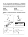
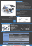
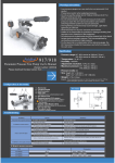
INSTALLATION AND OPERATION MANUAL
Electronic pressure switch with protection against dry running
ZD 15
Please read these manuals carefully before installation and application of the device. Both the installer and the end user must
respect the manuals in detail, also concerning the valid local regulations, rules and laws. The device complies with the valid regulations
the EU. The manufacturer assumes no liability for damages resulting from an incorrect application or an application under conditions
different from those indicated on the type plate or within this manual.
Cut off the power supply before opening the cover, if you want to remove the device or the switching cabinet.
RANGE OF APPLICATION AND SERVICES
Device for automatic control of electronic pumps in water units:
•
•
•
•
•
•
Replaces the traditional system with expansion tank
Switches the pump on or off, depending on opening or closing of the extraction points
Keeps the pressure constant during the extraction
Switches the pump off is case of water deficiency and ensures a protection against dry running
Prevents hydraulic shock effects
Requires no maintenance
TECHNICAL DATA
Voltage, single-phase
Permissible voltage fluctuations
Frequency
Current rating
Maximum output
230 V
+/-10%
50-60 Hz
16 (6) A
1.1 kW (1.5 HP)
Protection class
Device
Maximum operating pressure
Maximum operating temperature
External thread
IP 55
ZD 15
8 bar (0.8 MPa)
65 °C
G1" AG
Non-adjustable standard start-up pressure between min. 1.5 bar and max. 2 bar.
INSTALLATION (fig. 1 and 2)
Attention: Before installation, ensure that the technical characteristics of the device, the pump and the unit are compatible.
The pressure of then pump must amount to minimum 3.5 bar (0.35 MPa) and maximum 8 bar (0.8 MPa).
The water column between the device and the highest extraction point must not exceed 15 m.
If the pressure of the pump does not reach the above-mentioned values, the pump blocks or does not switch-off.
The pump starts but does not switch-on or it does not switch-off if the height of the water column exceeds the abovementioned values. In order to eliminate this disturbance, install the device at a higher position.
The device may be directly installed onto the pump or between the pump and the first extraction point (fig. 1). Install a pressure reducer
between the pump and the device if the inlet pressure at the device exceeds 8 bar (0.8 MPa). No extraction point must be installed
between the pump and the device (fig. 1). The device must be installed in such a manner that the arrows indicating the flow direction
point upwards (fig. 1/A). It is recommended to install a ball valve and a manometer at the outlet of the device, in order to check the
functionality of the pump and the device when they are separated from the unit using the valve and in order to determine the actual
discharge height of the pump using the manometer. The output of the device should be connected to the pump using a flexible hose (fig.
1/B). Before commissioning the device, make sure the pump is properly bled.
POWER CONNECTION (fig. 4)
The device may be connected to mains by qualified staff only and in accordance with the valid legal requirements. An all-phase switch
with a terminal distance of minimum 3 mm must always be connected head of the device. One-phase pumps (230 V) with a motor
output of up to 1.1 kW (1.5 HP) (fig. 4/A) may be connected directly to the device, while one-phase pumps with an output of
more than 1.1 kW (1.5 HP) (fig. 4/B) must connected via a contactor to the device. Check the mains voltage at the data indicated
on the type plate of the pump motor.
• Connect the electrical power as indicated in the graphs of fig. 4.
• Use cables of type HOS or H07 with a cross section of 3x1 mm2.
• Make sure the device is connected to the earthing system.
COMMISSIONING AND OPERATION (fig. 3)
The green lamp “power on” on the front side of the device shows that voltage is connected, while the yellow lamp “pump on” shows that
the pump in operation. If the device will be connected to the mains, the green and the yellow lamp light up. The latter shows that the
pump is started (fig. 3/A); it rests in operation for some seconds, in order that the unit may be pressured. If this time should not suffice,
push and hold the red button “restart” and wait until water leaves from an opened extraction point. After closing the extraction point, the
device deactivated the pump and rests in stand-by mode; in doing so, the green lamp remains switched-on and the device is ready to
execute all further command and control processes completely independent (fig. 3/B). When opening an extraction point, the device
activates the pump; it rests in operation until the extraction point is closed again (fig. 3/A). After closing the extraction point, the device
recovers the maximum pressure in the unit, switches the pump off and changes again to stand-by mode (fig. 3/B). If there is a water
deficiency during the intake process, the device switches the pump (fig. 3/C) off in order to protect it against dry running. As soon as the
disturbance which caused the blockage is removed, it is sufficient to push the red “restart” button in order to retake the normal operation.
In case of a temporary disturbance of the power supply, the device starts again automatically as soon as the power is reconnected.
DISTURBANCES
CHIEF CAUSE
• The pump does not start.
• The pump does not switch-on.
• The pump operates with disruptions.
• The pump does not switch-off.
• The pump is blocked.
Faulty power supply.
The water column is too high.
Water removal of the unit is lower than the minimum flow.
Loss of water in the unit is higher than the minimum flow.
Intake difficulties.
A defective switching cabinet may be replaced without removal of the device.
The switching cabinet is replaceable and can be delivered on request.
Further disturbances and causes different to the above-mentioned may be prevented or removed by carefully checking the
characteristics of the device, the pump and the unit considering the instructions in the section on installation.
FIGURES
Attention!
The pressure switch may only
be assembled in vertical
position (arrow points upwards)
Direct connection to
one-phase 230 V motors
with a maximum power input
of 1.1 kW.
Connection via a contactor to
one-phase 230 V motors
with a power input of more than 1.1 kW.