1
Front cover
PV Inverter
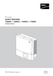
SUNNY MINI CENTRAL 9000TL / 10000TL / 11000TL
with Reactive Power Control
Installation Manual
SMC9-11TLRP-IA-en-51 | IMEN-SMCTLRP | Version 5.1
SMA Solar Technology AG
Table of Contents
Table of Contents
1
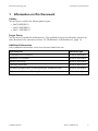
Information on this Document .....................................................7
2
Safety...........................................................................................10
2.1
2.2
2.3
Intended Use ............................................................................. 10
Qualifications of Skilled Persons.............................................. 11
Safety Precautions..................................................................... 12
3
Scope of Delivery .......................................................................13
4
Product Description.....................................................................15
4.1
4.2
4.3
4.4
4.5
4.6
4.7
4.8
4.9
4.10
4.11
5
Mounting .....................................................................................25
5.1
5.2
6
Sunny Mini Central ................................................................... 15
Type Label ................................................................................. 17
Display and LEDs ...................................................................... 19
Electronic Solar Switch (ESS) ................................................... 20
SMA Power Balancer ............................................................... 21
Communication ......................................................................... 23
Grid Management.................................................................... 23
Fuse Holders for String Fuses ................................................... 23
Varistors ..................................................................................... 24
SMA Grid Guard...................................................................... 24
All-Pole Sensitive Residual-Current Monitoring Unit................ 24
Selecting the Mounting Location ............................................. 25
Mounting the Inverter ............................................................... 28
Electrical Connection...................................................................31
6.1
6.2
Safety during Electrical Connection......................................... 31
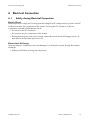
Overview of the Connection Area........................................... 32
6.2.1
6.2.2
6.3
Installation Manual
Bottom View ....................................................................................32
Interior View ....................................................................................33
AC Connection.......................................................................... 34
SMC9-11TLRP-IA-en-51
3
Table of Contents
SMA Solar Technology AG
6.3.1
6.3.2
6.3.3
6.4
DC Connection ......................................................................... 38
6.4.1
6.4.2
6.4.3
6.5
6.6
7
Conditions for AC Connection .......................................................34
Connecting the Inverter to the Electricity Grid...............................35
Additional Earthing of the Enclosure .............................................37
Conditions for DC Connection .......................................................38
Assembling the DC Connectors .....................................................38
Connecting the PV Array ................................................................41
Connecting the SMA Power Balancer..................................... 43
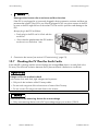
Installing the String Fuses ......................................................... 45
Configuration ..............................................................................47
7.1
7.2
7.3
7.4
Checking the Function of the SMA Power Balancer and
Setting the Operating Mode.................................................... 47
Changing the Country Data Set .............................................. 48
Setting the Country Data Set for Operation with External
Decoupling Protection .............................................................. 49
Changing the Display Language ............................................. 50
8
Commissioning............................................................................51
9
Disconnecting the Inverter .........................................................53
10 Troubleshooting ..........................................................................56
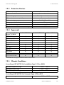
10.1 LED Signals................................................................................ 56
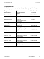
10.2 Display Messages..................................................................... 58
10.2.1 Measurement Channels..................................................................58
10.2.2 Status Messages .............................................................................59
10.2.3 Errors, Faults, Warnings..................................................................60
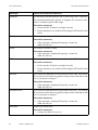
10.3
10.4
10.5
10.6
10.7
10.8
4
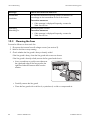
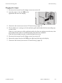
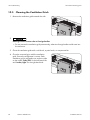
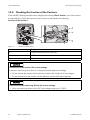
Cleaning the Fans ..................................................................... 66
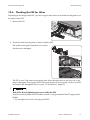
Checking the Fans..................................................................... 68
Cleaning the Ventilation Grids ................................................. 70
Checking the ESS for Wear ..................................................... 71
Checking the PV Plant for Earth Faults..................................... 72
Checking the Function of the Varistors..................................... 74
SMC9-11TLRP-IA-en-51
Installation Manual
SMA Solar Technology AG
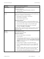
10.9
10.10
10.11
10.12
Table of Contents
Replacing the Varistors ............................................................. 76
Checking the Function of the String Fuses ............................... 77
Replacing the String Fuses........................................................ 79
Cleaning the Inverter ................................................................ 79
11 Decommissioning........................................................................80
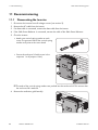
11.1 Dismounting the Inverter........................................................... 80
11.2 Packing the Inverter................................................................... 81
11.3 Disposing of the Inverter........................................................... 81
12 Technical Data.............................................................................82
12.1 DC/AC ...................................................................................... 82
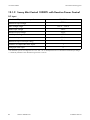
12.1.1 Sunny Mini Central 9000TL with Reactive Power Control ...........82
12.1.2 Sunny Mini Central 10000TL with Reactive Power Control .........84
12.1.3 Sunny Mini Central 11000TL with Reactive Power Control .........86
12.2
12.3
12.4
12.5
12.6
12.7
12.8
12.9
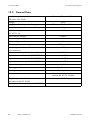
General Data ............................................................................ 88
Protective Devices ..................................................................... 89
Approvals .................................................................................. 89
Climatic Conditions................................................................... 89
Features ..................................................................................... 90
Electronic Solar Switch ............................................................. 90
Torques ...................................................................................... 90
Earthing Systems ....................................................................... 90
13 Accessories ..................................................................................91
14 Contact.........................................................................................92
Installation Manual
SMC9-11TLRP-IA-en-51
5
Table of Contents
6
SMC9-11TLRP-IA-en-51
SMA Solar Technology AG
Installation Manual
SMA Solar Technology AG
1 Information on this Document
1 Information on this Document
Validity
This document is valid for the following device types:
• SMC 9000TLRP-10
• SMC 10000TLRP-10
• SMC 11000TLRP-10
STSatz_Zielgruppe_Fachkräfte
Target Group
This document is intended for skilled persons. Only qualified personnel are allowed to perform the
tasks described in this manual (see section 2.2 "Qualifications of Skilled Persons", page 11).
STSatz_Hinw_Weiterführende Informationen
Additional Information
Links to additional information can be found at www.SMA-Solar.com:
Document title
Document type
Three-Phase Grid Connection
Technical information
Miniature Circuit-Breaker
Technical information
Module Technology
Technical information
Operating Parameters
Technical description
Insulation Resistance (Riso) of Non-Galvanically Isolated PV Plants
Technical information
PV Inverters ‒ Overview of Country Data Sets
Technical description
STSatz_Hinw_Symbole
Installation Manual
SMC9-11TLRP-IA-en-51
7
1 Information on this Document
SMA Solar Technology AG
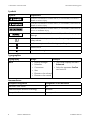
Symbols
Symbol
Explanation
Indicates a hazardous situation which, if not avoided, will result in
death or serious injury
Indicates a hazardous situation which, if not avoided, could result in
death or serious injury
Indicates a hazardous situation which, if not avoided, could result in
minor or moderate injury
Indicates a situation which, if not avoided, could result in property
damage
Information that is important for a specific topic or goal, but is not
safety-relevant
Indicates a requirement for achieving a specific goal
Desired result
A problem that might occur
Typographies
Typography
Usage
Bold
Example
• Display messages
• Parameter
• The inverter displays the status
Balanced.
• Select the parameter FanTest
and set it to 1.
• Connections
• Slots
• Elements to be selected
• Elements to be entered
Nomenclature
Complete designation
Designation in this document
Electronic Solar Switch
ESS
SMA Bluetooth Wireless Technology
Bluetooth
Sunny Mini Central
Inverter, product
®
8
SMC9-11TLRP-IA-en-51
Installation Manual
SMA Solar Technology AG
1 Information on this Document
Abbreviations
Abbreviation
Designation
Explanation
AC
Alternating Current
‒
DC
Direct Current
‒
DSP
Digital Signal Processor
‒
EC
European Community
‒
EEPROM
Electrically Eraseable
Programmable Read-Only
Memory
‒
LED
Light-Emitting Diode
‒
MPP
Maximum Power Point
‒
MSL
Mean Sea Level
‒
OCU
Operation Control Unit
‒
PC
Personal Computer
‒
PE
Protective Earth
Protective conductor
PV
Photovoltaics
‒
RP
Reactive Power
‒
Installation Manual
SMC9-11TLRP-IA-en-51
9
2 Safety
SMA Solar Technology AG
2 Safety
2.1
Intended Use
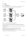
The Sunny Mini Central is a transformerless PV inverter, which converts the direct current of the
PV array to grid-compliant alternating current and feeds it into the electricity grid.
Aufgabe_SMC-TL
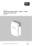
Figure 1:
Design of a PV plant with three Sunny Mini Central inverters
The Sunny Mini Central is suitable for indoor and outdoor use.
The Sunny Mini Central should only be operated with PV arrays (PV modules and cabling) of
protection class II. The PV modules used must be released by the module manufacturer for use with
this Sunny Mini Central.
PV modules with a high capacity to earth should only be used if their coupling capacity does not
exceed 1,400 nF.
All components must remain within their permitted operating ranges at all times.
The product may only be used in countries for which it is approved or released by
SMA Solar Technology AG and the network operator.
For safety reasons, it is forbidden to modify the product or install components that are not explicitly
recommended or distributed by SMA Solar Technology AG.
National approval and release
STSatz_Best Verwend_Produkt ändern
10
SMC9-11TLRP-IA-en-51
Installation Manual
SMA Solar Technology AG
2 Safety
Only use the Sunny Mini Central in accordance with the information provided in the enclosed
documentation. Any other application may cause injury to persons or lead to property damage.
• Do not mount the product on flammable construction materials.
Mounting the Product
• Do not mount the product in areas where highly flammable materials are stored.
• Do not install the product in potentially explosive atmospheres.
The enclosed documentation is an integral part of this product.
STSatz_Best Verwend_Doku beachten und zugänglich
• Read and observe the documentation.
• Keep the documentation in a convenient place for future reference.
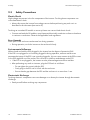
2.2
Qualifications of Skilled Persons
The work described in this document must be performed by skilled persons only. Skilled persons must
have the following qualifications:
• Knowledge of how an inverter works and is operated
• Training in how to deal with the dangers and risks associated with installing and operating
electrical devices and plants
• Training in the installation and commissioning of electrical devices and plants
• Knowledge of the applicable standards and directives
• Knowledge of and compliance with this document and all safety precautions
Installation Manual
SMC9-11TLRP-IA-en-51
11
2 Safety
2.3
SMA Solar Technology AG
Safety Precautions
Electric Shock
High voltages are present in the live components of the inverter. Touching these components can
cause fatal electric shock.
SiHiw_Stromschlag durch hohe Spannungen
• Always disconnect the inverter from voltage sources before performing any work on it as
described in this document (see section 9).
Touching an unearthed PV module or an array frame can cause a fatal electric shock.
SiHiw_nicht geerdetes PV-Modul
• Connect and earth the PV modules, array frame and electrically conductive surfaces so that there
is continuous conduction. Observe the applicable local regulations.
Burn Hazards
Some parts of the enclosure can become hot during operation.
SiHiw_Verbrennungen durch Gehäuseteile
• During operation, touch the inverter on the enclosure lid only.
Environmental Influences
When closed and with the ESS plugged in, the inverter has the degree of protection IP65.
SiHiw_ESS_Dichtigkeit
If the ESS is not plugged in or incorrectly plugged in during operation, moisture and dust can
penetrate the inverter. If the ESS is not correctly plugged in, this can cause contacts in the ESS to wear
or the ESS might fall out of the socket. This can result in yield loss and damage to the ESS.
• If the ESS is not plugged in, the inverter must be protected against moisture and dust.
• After performing any work on inverters, plug the ESS back in as follows:
– Do not tighten the screw inside the ESS.
– Firmly plug in the ESS until it is flush with the enclosure.
– Ensure that the gap between the ESS and the enclosure is no more than 1 mm.
Electrostatic Discharge
Touching electronic components can cause damage to or destroy the inverter through electrostatic
discharge.
SiHiw_Vor Berühren erden
• Earth yourself before touching any components.
12
SMC9-11TLRP-IA-en-51
Installation Manual
SMA Solar Technology AG
3 Scope of Delivery
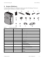
3 Scope of Delivery
Check the scope of delivery for completeness and any externally visible damage. Contact your
specialist dealer if the delivery is incomplete or damaged.
STSatz_Lieferumfang_Inhalt prüfen
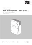
Figure 2:
Components of the delivery
Position
Quantity
Designation
A
1
Sunny Mini Central
B
2
Ventilation grid
C
1
Wall mounting bracket
D
1
Electronic Solar Switch
E
5
Positive DC connector
F
5
Negative DC connector
G
10
Sealing plug
H
1
Cable gland
I
1
Counter nut
K
1
Clamping bracket
L
2
Conical spring washer*
M
2
M6x16 cheese-head screw*
N
1
Jumper
O
2
M6x8 cheese-head screw
P
1
Y cable**
Installation Manual
SMC9-11TLRP-IA-en-51
13
3 Scope of Delivery
SMA Solar Technology AG
Position
Quantity
Designation
Q
1
Installation manual, user manual, document set
with explanations and certificates,
supplementary sheet with the default settings
* 1 spare part for the enclosure lid included
** Optional
14
SMC9-11TLRP-IA-en-51
Installation Manual
SMA Solar Technology AG
4 Product Description
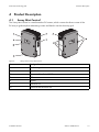
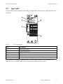
4 Product Description
4.1
Sunny Mini Central
The Sunny Mini Central is a transformerless PV inverter, which converts the direct current of the
PV array to grid-compliant alternating current and feeds it into the electricity grid.
Aufgabe_SMC-TL
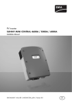
Figure 3:
Design of the Sunny Mini Central
Item
Designation
A
Ventilation grid
B
Type label
C
Electronic Solar Switch (ESS)
D
LEDs
E
Display
F
Enclosure lid
G
Screws of the enclosure lid
Installation Manual
SMC9-11TLRP-IA-en-51
15
4 Product Description
SMA Solar Technology AG
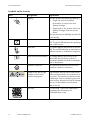
Symbols on the Inverter
Icon
Designation
Explanation
Tapping
You can operate the display by tapping it:
• Single tap: Switch on display
illumination or switch to the next
display message.
• Tapping twice: The inverter shows the
display messages from the start-up
phase.
After two minutes, the backlight switches off
automatically.
Inverter
This symbol defines the function of the green
LED. The green LED indicates the operating
state of the inverter.
Earth fault
This symbol defines the function of the red
LED. The red LED indicates an earth fault, a
defective varistor or a defective string fuse.
Observe the documentation. This symbol defines the function of the
yellow LED which indicates a fault or
disturbance. Read the manual to remedy the
fault or disturbance.
16
Protective conductor
This symbol indicates the position for the
protective conductor connection.
Danger to life due to high
voltages in the inverter;
observe waiting time.
High voltages that can cause fatal electric
shocks are present in the live components of
the inverter. The capacitors take ten minutes
to discharge. Prior to performing any work
on the inverter, disconnect it from all voltage
sources, as described in this document
(see section 9).
QR Code®
The QR Code® links to the SMA Bonus
Programme (for information see
www.SMA-Bonus.com).
SMC9-11TLRP-IA-en-51
Installation Manual
SMA Solar Technology AG
4.2
4 Product Description
Type Label
The type label uniquely identifies the inverter. The type label is located on the right-hand side of the
enclosure.
Figure 4:
Layout of the type label
Item
Explanation
A
Inverter device type
B
Inverter serial number
C
Device-specific characteristics
D
Field for additional information, e.g. details of standards
E
Inverter manufacture date (year-month-day)
You require the information on the type label to use the product safely and for questions to the
SMA Service Line. The type label must be permanently attached to the product.
STSatz_Typenschild_Funktionsbeschreibung
Installation Manual
SMC9-11TLRP-IA-en-51
17
4 Product Description
SMA Solar Technology AG
Symbols on the Type Label
SMCTLRP_Tabelle Symbole auf Typenschild
Icon
18
Designation
Explanation
Danger to life due to high
voltages
The inverter operates at high voltages.
All work on the inverter must be carried
out by skilled persons only.
Risk of burns from hot surfaces
The inverter can get hot during
operation. Avoid contact during
operation. Allow the inverter to cool
down sufficiently before carrying out
any work. Wear personal protective
equipment such as safety gloves.
Observe the documentation.
Observe all documentation that is
supplied with the inverter.
DC
Direct current
Without transformer
The inverter does not have a transformer.
AC
Alternating current
Proper disposal
Do not dispose of the inverter together
with the household waste.
CE marking
The inverter complies with the
requirements of the applicable EU
directives.
Degree of protection
The inverter is protected against dust
intrusion and water jets from any angle.
Outdoor
The inverter is suitable for outdoor
installation.
RAL quality mark for solar
products
The inverter complies with the
requirements of the German Institute for
Quality Assurance and Labelling.
Australian mark of conformity
The inverter complies with the
requirements of the applicable
Australian guidelines.
SMC9-11TLRP-IA-en-51
Installation Manual
SMA Solar Technology AG
Icon
4.3
4 Product Description
Designation
Explanation
Korean mark of conformity
The inverter complies with the
requirements of the applicable Korean
guidelines.
Chinese mark of conformity
The inverter complies with the
requirements of the applicable Chinese
guidelines.
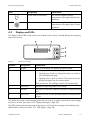
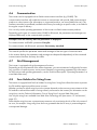
Display and LEDs
The display and the LEDs of the inverter are located on the enclosure lid and indicate the operating
state of the inverter.
Figure 5:
Design of the display
Position
Designation
Explanation
A
Display
2-line LC text display for displaying operating data
B
Tap symbol
You can operate the display by tapping it:
• Tapping once: Switch on display illumination or switch to
the next display message.
• Tapping twice in quick succession: The inverter shows the
display messages from the start-up phase.
After two minutes, the backlight switches off automatically.
C
Green LED
Indicates the operating state of the inverter.
D
Red LED
Indicates an earth fault, a defective varistor or a defective string
fuse.
E
Yellow LED
Indicates an error or fault. Read the manual to rectify the error
or fault.
The display shows the current operating data of the inverter (e.g. mode, performance, input voltage)
and errors or faults (see section 10.2 "Display Messages", page 58).
The LEDs indicate the operating state of the inverter, and clarify the messages in the display using
different blink codes (see section 10.1 "LED Signals", page 56).
Installation Manual
SMC9-11TLRP-IA-en-51
19
4 Product Description
4.4
SMA Solar Technology AG
Electronic Solar Switch (ESS)
The ESS and the DC connectors form a DC load disconnect unit.
Aufgabe_ESS
There are two types of ESS with different plug designs. The function of the ESS is identical in both
cases.
Figure 6:
Example of ESS design with visible metal mounting tab
Item
Designation
Explanation
A
Plug
Depending on the type of ESS, the metal
mounting tabs in the plug are visible or in a
plastic enclosure.
B
Label
•
If the ESS is plugged in, the DC
electric circuit is closed.
•
To interrupt the DC electric circuit,
you must first perform steps 1 and 2
consecutively.
•
Remove the ESS.
•
Remove all DC connectors.
When plugged in, the ESS forms a conductive path between the PV array and the inverter. Removing
the ESS interrupts the DC electric circuit and removing all DC connectors disconnects the PV array
completely from the inverter.
Funktion_ESS
20
SMC9-11TLRP-IA-en-51
Installation Manual
SMA Solar Technology AG
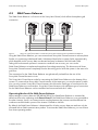
4.5
4 Product Description
SMA Power Balancer
The SMA Power Balancer is a function of the Sunny Mini Central, which allows three-phase grid
connection.
Figure 7:
Design of a three-phase feed-in unit with three Sunny Mini Central inverters with SMA Power Balancer
Using the SMA Power Balancer, you can connect three Sunny Mini Central inverters to a three-phase
feed-in unit, preventing unbalanced loads. Unbalanced load refers to power fed-in asymmetrically,
which depends on the country data set selected and may be between 4.6 kVA and 6 kVA.
Taking the local network operator's connection conditions into account, you can use the
SMA Power Balancer to implement three-phase line-voltage monitoring. This disconnects all three
Sunny Mini Central inverters completely from the electricity grid or limits their power in the event of a
grid error.
The connections for the SMA Power Balancer are galvanically isolated from the rest of the
Sunny Mini Central electronic circuit.
This Sunny Mini Central has a socket for connecting the SMA Power Balancer to the bottom of the
inverter. To connect three Sunny Mini Central inverters of the same type, you need a special Y cable.
You can only connect Sunny Mini Central inverters which have the same type of connection for the
SMA Power Balancer to one another. Sunny Mini Central inverters with a different type of connection
for the SMA Power Balancer can be retrofitted and connected with the Y cable.
Operating Modes of the SMA Power Balancer
Wenn setting the country data set VDE-AR-N4105-HP, the SMA Power Balancer is activated by
default and set to the operating mode PowerGuard. If the SMA Power Balancer is not connected to
the other inverters, there is no communicative coupling between the inverters and the different line
conductors and the feed-in power of the inverter is limited to 4.6 kVA.
Erläuterung_SMCTLRP_Power Balancer
By default, the SMA Power Balancer is deactivated for all other country data sets and can only be
activated with an SMA communication product. To activate the SMA Power Balancer, you can choose
from three operating modes.
Installation Manual
SMC9-11TLRP-IA-en-51
21
4 Product Description
SMA Solar Technology AG
Operating mode
Explanation
Off
The SMA Power Balancer is deactivated (default setting).
If one of the three inverters indicates a line voltage error or a device
fault, only the inverter affected disconnects from the electricity grid.
The other two inverters continue to feed in at full power.
FaultGuard
This operating mode allows you to implement three-phase line-voltage
monitoring, which also reacts to device faults.
• If one of the three inverters indicates a line-voltage error and
stops feeding in, the other two inverters also disconnect from the
electricity grid immediately.
• If one of the three inverters indicates a device fault and stops
feeding in, the other two inverters also disconnect from the
electricity grid after five minutes.
PhaseGuard
This operating mode allows you to implement three-phase line-voltage
monitoring.
• If one of the three inverters indicates a line-voltage error and
stops feeding in, the other two inverters also disconnect from the
electricity grid immediately.
• If one of the three inverters indicates a device fault and stops
feeding in, the other two inverters continue to feed in at full
power.
PowerGuard
You can select this operating mode if the entire PV plant consists only
of three Sunny Mini Central inverters and, in the event of an error,
unbalanced load is to be limited to between 4.6 kVA and 6 kVA
depending on the country data set selected.
• If one of the three inverters indicates a line voltage error or
device fault and stops feeding in, the other two inverters
automatically limit their power to between 4.6 kVA and 6 kVA
depending on the country data set selected.
22
SMC9-11TLRP-IA-en-51
Installation Manual
SMA Solar Technology AG
4.6
4 Product Description
Communication
The inverter can be equipped with an SMA communication interface (e.g. RS485). This
communication interface will enable the inverter to communicate with special SMA communication
products or other inverters (for information on supported products, see www.SMA-Solar.com). The
interface can either be retrofitted, installed at the factory according to a specific order, or included in
the regular scope of delivery.
You can only set the operating parameters of the inverter via SMA communication products.
Depending on the type of communication, RS485 or Bluetooth, the parameters and messages are
displayed differently on the communication products.
Example: How the country data set parameter is displayed
For communication via RS485: parameter CntrySet
For communication with Bluetooth: parameter Set country standard
This manual specifies the parameter names and messages of the two types of communication.
In the inverter display, the parameters and messages are depicted independently of the connected
communication interface and may also differ.
4.7
Grid Management
The inverter is equipped with grid management functions.
Depending on the requirements of the network operator, you can activate and configure the functions
(e.g. provision of reactive power, active power limitation) via operating parameters (for information
on the functions and operating parameters, see the Technical Description "Operating Parameters" at
www.SMA-Solar.com).
Funktionsweise_Einspeisemanagement-Funktion mit Internetverweis
4.8
Fuse Holders for String Fuses
The inverter is equipped with five fuse holders for string fuses. String fuses allow the inverter to protect
the PV modules against possible reverse currents.
Whether you have to install string fuses in the inverter depends on the reverse-current resistance of the
PV modules used and the number of strings directly connected to the inverter (for information on the
string fuses, see the Technical Information "Use of String Fuses" at www.SMA-Solar.com).
Use only the string fuses available from SMA Solar Technology AG (see section 13 "Accessories",
page 91).
Note that the string fuses are a precautionary measure only to minimise the risk of fire in the event of
an error, for example. Using string fuses does not guarantee that the PV array is protected against
consequential damage.
Installation Manual
SMC9-11TLRP-IA-en-51
23
4 Product Description
4.9
SMA Solar Technology AG
Varistors
Varistors are voltage-dependent resistors that protect the inverter against overvoltage. The inverter is
equipped with thermally monitored varistors.
Varistors can become worn and lose their protective function with age or repeated strain as a result
of overvoltage. The inverter detects if one of the varistors is defective and indicates an error
(see section 10 "Troubleshooting", page 56).
The varistors are specially manufactured for use in the inverter and are not commercially available.
You must order new varistors directly from SMA Solar Technology AG.
4.10 SMA Grid Guard
SMA Grid Guard acts as an automatic disconnection device between a grid-parallel generator
(e.g. a PV plant or small wind turbine system) and the electricity grid.
SMA Grid Guard is also a grid monitoring concept which detects errors by permanently monitoring
grid impedance, mains voltage and mains frequency. For example, SMA Grid Guard detects when a
stand-alone grid is formed and disconnects the inverter from the electricity grid immediately.
In some countries, the connection conditions require a device which protects grid-relevant operating
parameters against unpermitted changes. SMA Grid Guard performs this function.
Some country data sets are automatically protected after the first ten feed-in hours. The protected
country data sets can only be changed via a communication product on entry of a personal access
code, the SMA Grid Guard code, after ten feed-in hours (for information on changing parameters,
see the manual for the communication product). You will receive the SMA Grid Guard code from
SMA Solar Technology AG (to apply for the SMA Grid Guard code, see the certificate
"Application for SMA Grid Guard Code" at www.SMA-Solar.com).
4.11 All-Pole Sensitive Residual-Current Monitoring Unit
The inverter is equipped with an all-pole sensitive residual-current monitoring unit with an integrated
differential current sensor.
The all-pole-sensitive residual-current monitoring unit detects alternating and direct differential
currents. The integrated differential current sensor detects the current difference between the neutral
conductor and the number of line conductors for single-phase and three-phase inverters. If the current
difference increases suddenly, the inverter disconnects from the electricity grid.
If an external residual-current device is required or planned, you must install a residual-current device
which trips at a residual current of 100 mA or higher. That ensures that the inverter does not
disconnect from the electricity grid due to leakage currents caused by operation. If the locally
applicable installation regulations require the use of a residual-current device that trips at a lower
residual current, e.g. 30 mA, leakage currents caused by operation can cause false tripping.
24
SMC9-11TLRP-IA-en-51
Installation Manual
SMA Solar Technology AG
5 Mounting
5 Mounting
5.1
Selecting the Mounting Location
Requirements for the mounting location:
WaHiw_Lebensgefahr durch Feuer und Explosion
Danger to life due to fire or explosion
Despite careful construction, electrical devices can cause fires.
• Do not mount the inverter on flammable construction materials.
• Do not mount the inverter in areas where highly flammable materials are stored.
• Do not mount the inverter in a potentially explosive atmosphere.
☐ The mounting location must be inaccessible to children.
☐ A solid surface must be available for mounting, e.g. concrete or masonry. When mounted on
plasterboard or similar materials, the inverter will develop audible vibrations during operation,
which could be considered disturbing.
☐ It may not be mounted on a pillar.
☐ The mounting location must be suitable for the weight and dimensions of the inverter
(see section 12 "Technical Data", page 82).
☐ The mounting location must be freely and safely accessible at all times without the necessity for
any auxiliary equipment, such as scaffolding or lifting platforms. Non-fulfillment of these criteria
may restrict servicing.
☐ The installation site should not be exposed to direct solar irradiation. Direct solar irradiation can
heat up the inverter excessively. As a result, the inverter reduces its power output.
☐ Climatic conditions must be met (see section 12 "Technical Data", page 82).
☐ The ambient temperature must be below 40°C to ensure the optimal operation of the inverter.
Installation Manual
SMC9-11TLRP-IA-en-51
25
5 Mounting
SMA Solar Technology AG
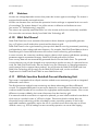
Dimensions for wall mounting:
Figure 8:
26
Dimensions of the wall mounting bracket and dimensions of the holes for the optional anti-theft device in the
inverter enclosure
SMC9-11TLRP-IA-en-51
Installation Manual
SMA Solar Technology AG
5 Mounting
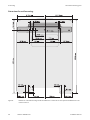
Observe recommended clearances:
Figure 9:
Recommended clearances
• Observe the recommended clearances to the walls as well as to other inverters or objects.
This ensures adequate heat dissipation and sufficient space to remove the ESS.
• If multiple inverters are mounted in areas with high ambient temperatures, increase the
clearances between the inverters and ensure an adequate fresh-air supply.
☑ This prevents a reduction in inverter power as a result of high temperatures (details on
temperature derating can be found in the Technical Information "Temperature Derating" at
www.SMA-Solar.com).
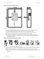
Observe the permitted mounting position:
Figure 10:
Permitted and prohibited mounting positions
• Mount the inverter in a permitted mounting position. The display should be mounted at eye level.
☑ Mounting the inverter in a permissible position will ensure that no moisture can enter.
☑ By mounting the device at eye level, display messages and LED signals can be read without
difficulty.
Installation Manual
SMC9-11TLRP-IA-en-51
27
5 Mounting
5.2
SMA Solar Technology AG
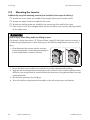
Mounting the Inverter
Additionally required mounting material (not included in the scope of delivery):
☐ At least two screws which are suitable for the weight of the inverter and the surface
☐ At least two washers that are suitable for the screws
☐ At least two wall plugs that are suitable for the mounting surface and for the screws
☐ If the inverter is to be secured against theft, at least one safety screw and one wall plug suitable
for the safety screw
WaHiw_Verletzungsgefahr durch hohes Gewicht
Risk of injury when lifting and from falling inverter
The inverter is heavy (see section 12 "Technical Data", page 82). Lifting the inverter incorrectly, or
if it falls during transportation or while attaching it to the wall mounting bracket result in a risk of
injury.
• Lift and transport the inverter into the mounting
position horizontally. Use the side recessed grips or
a steel rod (diameter: maximum 30 mm).
1. Ensure that there are no cables in the wall which could be damaged when drilling.
2. Align the wall mounting bracket horizontally on the wall and use it to mark the position of the
drill holes. Use at least one hole on the left-hand side and one on the right-hand side of the wall
mounting bracket.
3. Drill the holes and insert the wall plugs.
4. Secure the wall mounting bracket horizontally on the wall using screws and washers.
28
SMC9-11TLRP-IA-en-51
Installation Manual
SMA Solar Technology AG
5 Mounting
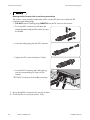
5. If the inverter is to be secured against theft, mark the drill hole for the attachment of the safety
screw:
• Hook the inverter into the wall mounting
bracket.
• Mark the drill hole on the left-hand side or
right-hand side. If you want to secure the
inverter with two safety screws, mark both drill
holes.
• Remove the inverter by lifting it up vertically
and out of the wall mounting bracket.
• Drill the hole or holes to attach the safety screw and insert the wall plug(s).
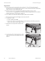
6. Hook the inverter into the wall mounting bracket.
Installation Manual
SMC9-11TLRP-IA-en-51
29
5 Mounting
SMA Solar Technology AG
7. Attach the inverter to the wall mounting bracket
on both sides using the M6x8 screws provided
and an Allen key (AF 5). Only tighten the screws
hand-tight. That prevents the inverter being lifted
out.
8. Close the recessed grips with the ventilation
grids. Ensure the assignment is correct. The
correct assignment is marked on the inside of
each ventilation grid: links/left for the left-hand
side and rechts/right for the right-hand side.
9. If the holes for attaching the safety screw are
pre-drilled, secure the inverter with at least one
safety screw through the pre-drilled hole.
10. Ensure that the inverter is securely attached.
30
SMC9-11TLRP-IA-en-51
Installation Manual
SMA Solar Technology AG
6 Electrical Connection
6 Electrical Connection
6.1
Safety during Electrical Connection
Electric Shock
When exposed to sunlight, the PV array generates dangerous DC voltage which is present in the DC
conductors and the live components of the inverter. Touching the DC conductors or the live
components can lead to lethal electric shocks.
SiHiw_Stromschlag durch hohe Spannung
• Do not touch the DC conductors.
• Do not touch any live components of the inverter.
• Before performing any work on the inverter, always disconnect it from all voltage sources, as
described in this document (see section 9).
Electrostatic Discharge
Touching electronic components can cause damage to or destroy the inverter through electrostatic
discharge.
SiHiw_Vor Berühren erden
• Earth yourself before touching any components.
Installation Manual
SMC9-11TLRP-IA-en-51
31
6 Electrical Connection
6.2
6.2.1
Figure 11:
SMA Solar Technology AG
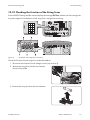
Overview of the Connection Area
Bottom View
Connection areas and enclosure openings at the bottom of the inverter
Item
Designation
Explanation
A
Positive DC connector with filler plug
For connecting the positive DC cables
B
Socket
For connecting the ESS
C
Negative DC connector with filler plug
For connecting the negative DC cables
D
Enclosure opening
For routing the data cables through
E
Socket
For connecting the SMA Power Balancer
F
Enclosure opening
For routing the AC cable through
32
SMC9-11TLRP-IA-en-51
Installation Manual
SMA Solar Technology AG
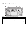
6.2.2
Figure 12:
6 Electrical Connection
Interior View
Components and connection areas in the interior of the inverter
Item
Designation
A
Jumper slot
For checking the fans
B
Terminal
For the AC cable
C
Flat male tabs
For earthing the cable shield of the
data cable
D
Screw fixture for the shield
connection terminal
For earthing the cable shield of the
data cable
E
Fuse
For the ESS
Installation Manual
Explanation
SMC9-11TLRP-IA-en-51
33
6 Electrical Connection
SMA Solar Technology AG
Item
Designation
F
Fuse holders
For installing the string fuses
G
Connection area and slot
For communication interfaces
6.3
Explanation
AC Connection
6.3.1
Conditions for AC Connection
Cable requirements:
☐ Conductor cross-section without bootlace ferrule: maximum 25 mm².
☐ Conductor cross-section with bootlace ferrule: maximum 10 mm².
☐ At a conductor cross-section of 25 mm², a flexible cable must be used.
☐ When designing the conductor cross-section, all factors must be taken into consideration
(see the design program "Sunny Design" from software version 2.0 at www.SMA-Solar.com).
☐ The maximum cable length subject to conductor cross-section must be observed. Useful hint: If
you group three inverters to a three-phase plant with symmetrical feed-in, the line losses are
halved. That doubles the maximum cable length possible.
☐ External diameter of the cable corresponds to the clamping range of the cable gland:
18 mm ... 32 mm.
☐ The cable must be dimensioned in accordance with any local and national guidelines on cable
dimensions which specify requirements for the minimum conductor cross-section. Examples of
factors influencing cable dimensioning are: nominal AC current, type of cable, routing method,
cable bundling, ambient temperature and maximum desired line losses (for calculation of line
losses, see design software Sunny Design from software version 2.0 www.SMA-Solar.com).
Switch-disconnector and cable protection:
WaHiw_Schraubsicherungen als Lasttrenneinrichtung
Damage to the inverter due to the use of screw-type fuses as switch-disconnectors
Screw-type fuses (e.g. DIAZED fuse or NEOZED fuse) are not switch-disconnectors.
• Do not use screw-type fuses as switch-disconnectors.
• Use a switch-disconnector or miniature circuit-breaker as a load disconnect unit (for information
and design examples, see the Technical Information "Miniature Circuit-Breaker" at
www.SMA-Solar.com).
• In plants with multiple inverters, protect every inverter with a separate miniature circuit-breaker.
Observe the maximum permissible fuse protection (see section 12 "Technical Data", page 82).
That prevents residual voltage being present at the corresponding cable after disconnection.
• Loads installed between the inverter and the miniature circuit-breaker must be protected
separately.
SMC_Fehlerstrom-Überwachungseinheit
34
SMC9-11TLRP-IA-en-51
Installation Manual
SMA Solar Technology AG
6 Electrical Connection
Residual-current monitoring unit:
• If an external residual-current device is required, install a residual-current device which trips at a
residual current of 100 mA or higher (for details on selecting a residual-current device, see the
Technical Information "Criteria for Selecting a Residual-Current Device" at www.SMA-Solar.com).
SMC Classic_Überspannungskategorie
Overvoltage category
The inverter can be used in grids of installation category III or lower in accordance with IEC 60664-1.
That means that the inverter can be permanently connected to the junction box of a building. In case
of installations with long outdoor cabling routes, additional measures to reduce overvoltage category
IV to overvoltage category III are required.
Protective conductor monitoring:
STP klein SMC_Schutzleiter-Überwachung
The inverter is equipped with protective conductor monitoring which detects when no protective
conductor is not connected and disconnects the inverter from the electricity grid.
Connection of an additional protective conductor
In some countries an additional earthing is required. In each case, observe the local
applicable regulations.
• If an additional earthing is required, earth the inverter (see section 6.3.3 "Additional
Earthing of the Enclosure", page 37). The conductor cross-section muss correspond to the
cross section of the original protective conductor. This prevents touch current if the original
protective conductor fails.
6.3.2
Connecting the Inverter to the Electricity Grid
Requirements:
☐ The display language must be set to the required language (see section 7.4 "Changing the
Display Language", page 50).
☐ The connection requirements of the network operator must be met.
☐ The mains voltage must be in the permissible range. The exact operating range of the inverter is
specified in the operating parameters (see the Technical Description "Operating Parameters" at
www.SMA-Solar.com).
1. Disconnect the miniature circuit-breaker and secure against reconnection.
2. Loosen all screws and conical spring washers of the enclosure lid and remove the lid.
3. Remove the adhesive tape from the enclosure opening for the AC cable.
4. Attach the cable gland to the enclosure opening for the AC cable using a counter nut.
5. Strip the AC cable insulation.
6. Shorten L and N by 5 mm each.
7. Strip 18 mm of the L, N and PE insulation each.
8. Route the AC cable into the inverter through the cable gland. If necessary, slightly loosen the
swivel nut of the cable gland.
Installation Manual
SMC9-11TLRP-IA-en-51
35
6 Electrical Connection
SMA Solar Technology AG
9. Connect the AC cable to the terminal block for the AC cable using a screwdriver:
• Connect PE to terminal PE.
• Connect N to terminal N.
• Connect L to terminal L.
10. Close the inverter and earth the enclosure lid:
• Attach one conical spring washer to each
screw. The grooved side of the conical spring
washer must point to the screw head.
• Secure the enclosure lid with screws in the
sequence 1 to 6 (torque: 6 Nm).
☑ The teeth of the conical spring washers are pushed into the enclosure lid. This ensures that
the enclosure lid is earthed.
36
SMC9-11TLRP-IA-en-51
Installation Manual
SMA Solar Technology AG
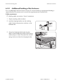
6.3.3
6 Electrical Connection
Additional Earthing of the Enclosure
You can additionally earth the inverter enclosure if a second earthing or equipotential bonding is
required locally. This prevents touch current if the original protective conductor fails.
Cable requirement:
☐ Earthing cable cross-section: 16 mm² at maximum
1. Strip the earthing cable insulation.
2. Lead the clamping bracket over the earthing
cable. Position the protective conductor on the
left-hand side.
3. Screw the clamping bracket tight using the
M6x16 cheese-head screw and a conical spring
washer (torque: 6 Nm). The teeth of the conical
spring washer must face the clamping bracket.
Installation Manual
SMC9-11TLRP-IA-en-51
37
6 Electrical Connection
6.4
SMA Solar Technology AG
DC Connection
6.4.1
Conditions for DC Connection
Requirements for the PV modules:
Funkt.Titel_Anforderungen an die PV-Module
☐ All PV modules must be of the same type.
☐ The same number of series-connected PV modules must be connected to all strings.
☐ All PV modules must be aligned identically.
☐ All PV modules must have the same tilt angle.
☐ The maximum input current per string must be maintained and must not exceed the through-fault
current of the DC connectors (see section 12 "Technical Data", page 82).
☐ The thresholds for the input voltage and the input current of the inverter must be observed
(see section 12 "Technical Data", page 82).
☐ At an ambient temperature over 10°C, the open-circuit voltage of the PV modules must not
exceed 90% of the maximum input voltage of the inverter. That prevents the voltage exceeding
the maximum input voltage of the inverter at lower ambient temperatures.
☐ The positive connection cables of the PV modules must be equipped with the positive DC
connectors.
☐ The negative connection cables of the PV modules must be equipped with the negative DC
connectors.
Wichtig_Parallelschaltung mit Y-Adapter
Use of Y adaptors for parallel connection of strings
The Y adaptors must not be used to interrupt the DC electric circuit.
• Do not use the Y adaptors in the immediate vicinity of the inverter. The adaptors must not
be visible or freely accessible.
• In order to interrupt the DC electric circuit, disconnect the inverter (see section 9).
6.4.2
Figure 13:
Assembling the DC Connectors
DC connectors
Item
Designation
A
Negative DC connector
B
Positive DC connector
38
SMC9-11TLRP-IA-en-51
Installation Manual
SMA Solar Technology AG
6 Electrical Connection
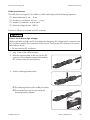
Cable requirements:
The cable must be of type PV1-F, UL-ZKLA or USE2 and comply with the following properties:
☐ External diameter: 5 mm … 8 mm.
☐ Conductor cross-section: 2.5 mm² … 6 mm²
☐ Number of conductors: at least seven
☐ Nominal voltage: at least 1,000 V
Proceed as follows to assemble each DC connector.
Electric shock due to high voltages
When exposed to sunlight, the PV array generates dangerous DC voltage which is present in the
DC conductors and the live components of the inverter. Touching the DC conductors can result in
lethal electric shocks.
• Do not touch the DC conductors.
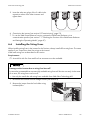
1. Strip 12 mm of the cable insulation.
2. Route the stripped cable all the way into the DC
connector. Ensure that the stripped cable and the
DC connector have the same polarity.
+
3. Push the clamping bracket down.
+
☑ The clamping bracket clicks audibly into place.
☑ The stranded wire can be seen inside the
clamping bracket chamber.
+
Installation Manual
SMC9-11TLRP-IA-en-51
39
6 Electrical Connection
SMA Solar Technology AG
✖ Is the stranded wire not visible in the chamber?
The cable is not correctly in place.
• Release the clamping bracket. To do so,
insert a screwdriver (blade width: 3.5 mm)
into the clamping bracket and lever it open.
2
1
+
• Remove the cable and go back to step 2.
4. Push the swivel nut up to the thread and tighten
(torque: 2 Nm).
1
2
+
40
SMC9-11TLRP-IA-en-51
Installation Manual
SMA Solar Technology AG
6.4.3
6 Electrical Connection
Connecting the PV Array
WaHiw_Leerlaufspannung darf max. Eingangsspannung nicht überschreiten
Destruction of the inverter due to overvoltage
If the open-circuit voltage of the PV modules exceeds the maximum input voltage of the inverter, the
inverter can be destroyed by the overvoltage.
• If the open-circuit voltage of the PV modules exceeds the maximum input voltage of the inverter,
do not connect any PV strings to the inverter and check the design of the PV plant.
1. Disconnect the miniature circuit-breaker and secure against reconnection.
2. If the ESS is plugged in, remove the ESS.
3. Remove the filler plugs from all the DC inputs on
the inverter.
4. Check strings for earth faults. Checking the PV Plant for Earth Faults.
5. Connect the assembled DC connectors to the
inverter.
☑ The DC connectors click audibly into place.
Installation Manual
SMC9-11TLRP-IA-en-51
41
6 Electrical Connection
SMA Solar Technology AG
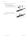
6.
Damage to the inverter due to moisture penetration
The inverter is only properly sealed when all the unused DC inputs are closed with DC
connectors and sealing plugs.
• DO NOT insert the sealing plugs DIRECTLY into the DC inputs on the inverter.
• For unused DC connectors, push down the
clamping bracket and push the swivel nut up to
the thread.
1
2
+
• Insert the sealing plug into the DC connector.
+
• Tighten the DC connector (torque: 2 Nm).
+
• Insert the DC connectors with sealing plugs
into the corresponding DC inputs on the
inverter.
☑ The DC connectors click audibly into place.
7. Ensure that all DC connectors are securely in place.
8. Check the ESS for wear (see section 10.6).
42
SMC9-11TLRP-IA-en-51
Installation Manual
SMA Solar Technology AG
6 Electrical Connection
9.
Risk of fire due to tightening the screw within the ESS
A perfect contact between the ESS and the inverter is only guaranteed if the ESS plug remains
flexible.
• Do not tighten the screw in the plug of the ESS.
10.
Damage to the inverter due to moisture and dust intrusion
If the ESS is not plugged in or incorrectly plugged in during operation, moisture and dust can
penetrate the inverter. If the ESS is not correctly plugged in, this can cause contacts in the ESS
to wear or the ESS might fall out of the socket. This can result in yield loss and damage to the
ESS.
Always plug in the ESS as follows:
• Firmly plug in the ESS until it is flush with the
enclosure.
• Ensure that the gap between the ESS and the
enclosure is no more than 1 mm.
6.5
Connecting the SMA Power Balancer
You need a special Y cable to connect the SMA Power Balancer. The Y cable is not a standard
accessory. You can order the Y cable from SMA Solar Technology AG (see section 13 "Accessories",
page 91).
The Y cable is designed for distances of maximum 2 m between two inverters. If the distance between
inverters is longer, you will have to extend the cable.
Requirements for the extension cord:
☐ Maximum cable length: 300 m
☐ Extension cord for indoor use: Li2YCY 1 x 2 x 0.25 mm², shielded, flexible, insulated, twisted
pair.
☐ Extension cord for outdoor use: Li2YCYv 1 x 2 x 0.25 mm², shielded, flexible, insulated, twisted
pair.
Installation Manual
SMC9-11TLRP-IA-en-51
43
6 Electrical Connection
SMA Solar Technology AG
Requirements:
☐ Every inverter must be connected to a line conductor L1, L2 or L3 of the electricity grid
(for information on the three-phase grid connection, see the Technical Information "Three-Phase
Grid Connection" at www.SMA-Solar.com).
☐ All three inverters must be equipped with the SMA Power Balancer plug-in system.
Hint: If an inverter is not equipped with a SMA Power Balancer plug-in system, you can order a
retrofit kit (see section 13 "Accessories", page 91).
☐ The Y cable for the SMA Power Balancer plug-in system must be available.
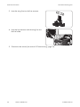
1. Disconnect the inverter from all voltage sources (see section 9).
2. To extend the Y cable:
• Cut the Y cable in the middle.
• Connect the conductors and cable shield 1:1 to the extension cord inside a junction box.
Observe the maximum cable length of 300 m.
3. Remove the screw cap from the socket of each
inverter.
4. Insert the plug of the Y cable with the two cable
inputs into the socket of the middle inverter and
tighten it.
44
SMC9-11TLRP-IA-en-51
Installation Manual
SMA Solar Technology AG
6 Electrical Connection
5. Insert the other two plugs of the Y cable in the
respective socket of the other inverters and
tighten them.
6. Commission the inverter (see section 8 "Commissioning", page 51).
7. To use the SMA Power Balancer function, activate the SMA Power Balancer via a
communication product (see section 7.1 "Checking the Function of the SMA Power Balancer
and Setting the Operating Mode", page 47).
6.6
Installing the String Fuses
When installing string fuses in the inverter for the first time, always install all five string fuses. The same
applies if you connect less than five strings to the inverter.
Install each string fuse as described in this section.
Requirement:
☐ A retrofit kit with five fuses and five fuse extractors must be available.
Damage to the inverter due to string fuse burn-off
It cannot be guaranteed that commercially available string fuses will function correctly. In the event
of an error, the string fuses can burn off.
• Use only the retrofit kits with string fuses available from SMA Solar Technology AG.
1. Disconnect the inverter from all voltage sources (see section 9).
2. Remove the jumper from the fuse holder using
insulated pliers.
Installation Manual
SMC9-11TLRP-IA-en-51
45
6 Electrical Connection
SMA Solar Technology AG
3. Insert the string fuse into the fuse extractor.
4. Insert the fuse extractor with the string fuse into
the fuse holder.
5. Commission the inverter (see section 8 "Commissioning", page 51).
46
SMC9-11TLRP-IA-en-51
Installation Manual
SMA Solar Technology AG
7 Configuration
7 Configuration
7.1
Checking the Function of the SMA Power Balancer and
Setting the Operating Mode
Requirements:
☐ The inverter must be equipped with a communication interface.
☐ A communication product, data logger or software appropriate for the type of communication
used must be available.
☐ The responsible network operator must approve changes of grid-relevant parameters.
☐ SMA Grid Guard code for changing grid-relevant parameters must be available (to apply for
an SMA Grid Guard code, see Certificate "Application for SMA Grid Guard Code" at
www.SMA-Solar.com).
1. Open the user interface of the data logger or software.
2. Enter the SMA Grid Guard code.
3. For all three inverters, select the parameter PowerBalancer or PowerBalancer operating
mode and set it to PhaseGuard.
4. Check whether all inverters display the message Mode MPP and whether the green LED of the
inverters is glowing.
If all inverters display the message PowerBalance, check the connection of the
SMA Power Balancer.
If the connection is correct and the problem persists, contact the SMA Service Line.
5. Switch off the miniature circuit-breaker of 1 inverter.
☑ The inverter with the deactivated miniature circuit-breaker displays the message Vac-Bfr and
disconnects from the electricity grid.
☑ The other two inverters display the message PowerBalance and also disconnect from the
electricity grid. They then display the message Balanced.
✖ The inverters do not disconnect from the electricity grid?
The connection of the SMA Power Balancer is probably faulty or the parameter
Power Balancer is not set to PhaseGuard.
• Check the connection and setting of the SMA Power Balancer. If the connection is correct
and the parameter PowerBalancer is set to PhaseGuard, contact the
SMA Service Line.
6. For all three inverters, select the parameter PowerBalancer or PowerBalancer operating
mode and set the required operating mode (description of the operating modes of the
SMA Power Balancer (see section 4.5)).
7. Switch the miniature circuit-breaker.
Installation Manual
SMC9-11TLRP-IA-en-51
47
7 Configuration
7.2
SMA Solar Technology AG
Changing the Country Data Set
By default, the inverter is set to a specific country data set. You can see the country data set to which
the inverter is set in the enclosed supplementary sheet with the default settings. If the country data set
does not apply at the installation location, you will need to change it (for information on the operating
parameters, see the Technical Descriptions "Operating Parameters" and "PV Inverters ‒ Overview of
Country Data Sets" at www.SMA-Solar.com).
Danger to life due to high voltages in the event of outage of the electricity grid
If you set the inverter to stand-alone grid operation OFF-Grid, you must not operate the inverter on
the electricity grid, but only on a stand-alone grid. As a result, the inverter fulfills the country-specific
grid connection standards and disconnects reliably from the electricity grid.
• If the inverter is set to OFF-Grid, never operate it directly on the electricity grid.
Requirements:
☐ The inverter must be equipped with a communication interface.
☐ A communication product, data logger or software appropriate for the type of communication
used must be available.
☐ The responsible network operator must approve changes of grid-relevant parameters.
☐ The SMA Grid Guard code for changing the grid-relevant parameters must be available
(to apply for an "SMA Grid Guard" code, see the certificate "Application for SMA Grid Guard
Code" at www.SMA-Solar.com).
1. Open the user interface of the data logger or software.
2. Enter the SMA Grid Guard code in the communication product (e.g. software).
3. Select the parameter Default or Set country standard and adjust the required country data
set.
48
SMC9-11TLRP-IA-en-51
Installation Manual
SMA Solar Technology AG
7.3
7 Configuration
Setting the Country Data Set for Operation with External
Decoupling Protection
For operating the PV plant with external decoupling protection, the inverter has an additional country
data set MVtgDirective or Medium-Voltage Directive. This country data set allows you to extend
the operating range of the inverter for voltage and frequency (for information on the operating
parameters and country data sets, see the technical descriptions "Operating Parameters and
"PV Inverters ‒ Overview of Country Data Sets" at www.SMA-Solar.com). This country data set should
only be selected if the PV plant is disconnected via external decoupling.
Electric shock due to lack of external decoupling protection
If you set the MVtgDirective or Medium-Voltage Directive country data set, you are only
allowed to operate the inverter with an external three-phase decoupling protection. Without
external three-phase decoupling protection, the inverter will not disconnect from the electricity grid
when the standard requirement is exceeded.
• Install external three-phase decoupling protection.
Requirements:
☐ The inverter must be equipped with a communication interface.
☐ A communication product, data logger or software appropriate for the type of communication
used must be available.
☐ The responsible network operator must approve changes of grid-relevant parameters.
☐ The SMA Grid Guard code for changing the grid-relevant parameters must be available
(to apply for an "SMA Grid Guard" code, see the certificate "Application for SMA Grid Guard
Code" at www.SMA-Solar.com).
1. Open the user interface of the data logger or software.
2. Enter the SMA Grid Guard code.
3. Select the parameter Default and set it to MVtgDirective or select the parameter Set country
standard and set it to Medium-Voltage Directive.
Installation Manual
SMC9-11TLRP-IA-en-51
49
7 Configuration
7.4
SMA Solar Technology AG
Changing the Display Language
You can change the display language of the inverter. Various languages are available depending on
the country data set selected.
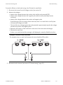
Figure 14:
Two switches at the bottom of the display assembly
1. Disconnect the inverter from all voltage sources (see section 9).
2. Select the required language via the two switches:
Language
Switch S2
Switch S1
German
B
B
English
B
A
French
A
B
Spanish
A
A
3. Commission the inverter (see section 8 "Commissioning", page 51).
50
SMC9-11TLRP-IA-en-51
Installation Manual
SMA Solar Technology AG
8 Commissioning
8 Commissioning
Initial Start-Up
When commissioning the inverter for the first time, proceed as follows.
Requirements:
☐ The miniature circuit-breaker must be correctly rated.
☐ The inverter must be correctly mounted and closed.
☐ All cables must be correctly connected.
☐ Unused DC inputs must be sealed using the corresponding DC connectors and sealing plugs.
☐ The ESS must be securely plugged in.
• Switch on the miniature circuit-breaker.
☑ The start-up phase begins. All three LEDs are glowing or flashing.
☑ The green LED is glowing and the start-up phase begins. The display shows the device type,
firmware version, country data set and operating mode of the SMA Power Balancer
consecutively. After the start-up phase has been completed, the current power, reactive power
and displacement power factor cos φ are displayed.
✖ Have all LEDs gone out?
The ESS is not plugged in or there is no DC input voltage.
• Plug in the ESS securely or wait until DC input voltage is present.
✖ Is the green LED flashing?
The DC input voltage is still too low.
• Once the DC input voltage is sufficiently high, the inverter will start to operate.
✖ Is the yellow or red LED glowing or flashing?
There is probably a fault or warning present.
• Rectify the fault or warning (see section 10.1 "LED Signals", page 56).
Recommissioning
If you have disconnected the inverter (e.g. for configuration purposes) and want to recommission it,
proceed as follows.
☐ The miniature circuit-breaker must be correctly rated.
☐ The inverter must be correctly mounted.
Installation Manual
SMC9-11TLRP-IA-en-51
51
8 Commissioning
SMA Solar Technology AG
1. Close the inverter and earth the enclosure lid:
• Attach one conical spring washer to each
screw. The grooved side of the conical spring
washer must point to the screw head.
• Secure the enclosure lid with screws in the
sequence 1 to 6 (torque: 6 Nm).
☑ The teeth of the conical spring washers are pushed into the enclosure lid. This ensures that
the enclosure lid is earthed.
2. Connect the DC connectors to the inverter.
3. Seal all unused DC inputs using the DC connectors with sealing plugs.
4. Check the ESS for wear (see section 10.6).
5. Switch on the miniature circuit-breaker.
☑ The start-up phase begins. All three LEDs are glowing or flashing.
☑ The green LED is glowing and the start-up phase begins. The display shows the device type,
firmware version, country data set and operating mode of the SMA Power Balancer
consecutively. After the start-up phase has been completed, the current power, reactive
power and displacement power factor cos φ are displayed.
✖ Have all LEDs gone out?
The ESS is not plugged in or there is no DC input voltage.
• Plug in the ESS securely or wait until DC input voltage is present.
✖ Is the green LED flashing?
The DC input voltage is still too low.
• Once the DC input voltage is sufficiently high, the inverter will start to operate.
✖ Is the yellow or red LED glowing or flashing?
There is probably a fault or warning present.
• Rectify the fault or warning (see section 10.1 "LED Signals", page 56).
52
SMC9-11TLRP-IA-en-51
Installation Manual
SMA Solar Technology AG
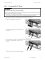
9 Disconnecting the Inverter
9 Disconnecting the Inverter
Before performing any work on the inverter, always disconnect it as described in this section.
1. Disconnect the miniature circuit-breaker and secure against reconnection.
2. Remove the ESS.
3. Use a current clamp to ensure that no current is
present in the DC cables.
4. Unlock and remove all DC connectors.
To do so, insert a slotted screwdriver (blade
width: 3.5 mm) into one of the side slots and pull
the DC connectors straight down. DO NOT
PULL ON THE CABLE whilst doing this.
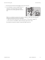
5.
Danger to life due to high voltages
The capacitors in the inverter take ten minutes to discharge.
• Wait ten minutes before opening the enclosure lid.
Installation Manual
SMC9-11TLRP-IA-en-51
53
9 Disconnecting the Inverter
SMA Solar Technology AG
6. Ensure that no voltage is present at the DC inputs
of the inverter using a suitable measuring device.
7. Unscrew all screws of the enclosure lid and
remove the enclosure lid.
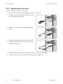
8. Ensure that no voltage is present between L and
N at the AC terminal using a suitable measuring
device.
9. Ensure that no voltage is present between L and
PE (
) at the AC terminal using a suitable
measuring device.
54
SMC9-11TLRP-IA-en-51
Installation Manual
SMA Solar Technology AG
9 Disconnecting the Inverter
10.
Damage to the inverter due to electrostatic discharge
The internal components of the inverter can be irreparably damaged by electrostatic discharge.
• Earth yourself before touching any components.
Installation Manual
SMC9-11TLRP-IA-en-51
55
10 Troubleshooting
SMA Solar Technology AG
10 Troubleshooting
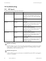
10.1 LED Signals
The LEDs indicate the operating state of the inverter.
Designation
Status
Explanation
Green LED
Glowing
Operation
The specific status message is shown in the
display (see section 10.2.2 "Status Messages",
page 59).
Red LED
Flashing
Conditions for grid connection are not yet
fulfilled.
Glowing
Earth fault
The specific error or fault message is shown in the
display (see section 10.2.3 "Errors, Faults,
Warnings", page 60).
Flashing
Varistor or string fuse defective
The specific error or fault message is shown in the
display (see section 10.2.3 "Errors, Faults,
Warnings", page 60).
Yellow LED
Glowing
Permanent operation inhibition
The specific error or fault message is shown in the
display (see section 10.2.3 "Errors, Faults,
Warnings", page 60).
Flashing
Error or fault
The specific error or fault message is shown in the
display (see section 10.2.3 "Errors, Faults,
Warnings", page 60).
All LEDs are flashing
If the DC voltage is very low in the start-up phase, all three LEDs go out and the start-up phase
begins again. If irradiation very low, all three LEDs flash. This flashing indicates a normal
operating state. It does not indicate an error.
All LEDs have gone out
If all three LEDs have gone out, the inverter is switched off because the ESS is not plugged in
or there is no irradiation.
56
SMC9-11TLRP-IA-en-51
Installation Manual
SMA Solar Technology AG
10 Troubleshooting
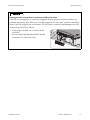
Damage to the inverter due to moisture and dust intrusion
If the ESS is not plugged in or incorrectly plugged in during operation, moisture and dust can
penetrate the inverter. If the ESS is not correctly plugged in, this can cause contacts in the ESS to
wear or the ESS might fall out of the socket. This can result in yield loss and damage to the ESS.
Always plug in the ESS as follows:
• Firmly plug in the ESS until it is flush with the
enclosure.
• Ensure that the gap between the ESS and the
enclosure is no more than 1 mm.
Installation Manual
SMC9-11TLRP-IA-en-51
57
10 Troubleshooting
SMA Solar Technology AG
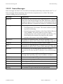
10.2 Display Messages
10.2.1 Measurement Channels
Measurement channels are measured values which are shown on the display. The measurement
channels can also be read out using a communication product.
Measurement channel
Explanation
Balancer
Indicates the operating mode of the inverter which is set under the
operating parameter PowerBalancer.
E-total
Total amount of energy fed in
Earthfault
Insulation resistance of the PV plant before connecting to the
electricity grid.
Error
Designation of the current fault or the current error
Event-Cnt
Number of events that have occurred
Fac
Mains frequency
h-On
Total operating hours
h-total
Total number of operating hours in feed-in operation
Iac-Ist
Line current
Ipv
Direct current
Is
Apparent current
Line conductor
The line conductor to which the inverter is connected.
Netz-Ein
Total number of grid connections
Pac
AC power supplied
PF
Displacement power factor cos φ. In partial load, the value displayed
may deviate from the set target value.
Qac
Reactive power
Sac
Apparent power
Serial number
Inverter serial number
Status
Indicates the current operating state
Upv-Soll
PV voltage setpoint
Vac
Mains voltage
Vpv
PV input voltage
58
SMC9-11TLRP-IA-en-51
Installation Manual
SMA Solar Technology AG
10 Troubleshooting
10.2.2 Status Messages
Status messages are shown in the second line of the display and always start with the word “Mode”.
Status messages indicate operating states which do not represent errors or faults. The inverter
continues feeding into the electricity grid.
Message
Explanation
Balanced
The inverter has disconnected from the electricity grid or is limiting its
power over a ten-minute average to 4.6 kVA. The inverter is part of a
three-phase system with two further inverters and is equipped with the
SMA Power Balancer to prevent the formation of unbalanced loads.
Derating
This message can have several causes:
• Overtemperature in the inverter. The inverter reduces its power
to prevent overheating.
• External active power limitation via the Power Reducer Box and
Sunny WebBox. The inverter reduces its power output
automatically due to the network operator's specifications. The
Power Reducer Box transfers the signal from the network
operator to the inverter via the Sunny WebBox.
disturbance
The inverter has detected a fault. The specific message is also
displayed (see section 10.2.3 "Errors, Faults, Warnings", page 60).
Earthfault
Measurement of the insulation resistance of the PV plant
Error
The inverter has detected an error. The specific error message is also
displayed (see section 10.2.3 "Errors, Faults, Warnings", page 60).
grid mon.
Grid monitoring. This message appears before the inverter is
connected to the electricity grid if irradiation is low and following an
error.
MPP
The inverter is operating in MPP mode. MPP is the standard display
message when operating under normal irradiation conditions.
MPP-Peak
The inverter is operating in MPP mode above its nominal power.
MPP-Search
The inverter is calculating the MPP.
offset
Offset alignment of the measurement electronics
Stop
Operation interrupted
V-Const
Constant voltage mode
Waiting
The conditions for grid connection are not (yet) fulfilled.
Installation Manual
SMC9-11TLRP-IA-en-51
59
10 Troubleshooting
SMA Solar Technology AG
10.2.3 Errors, Faults, Warnings
Errors, faults and warnings are shown in the display and start in the first line with the word "Error",
"Disturbance" or "Warning". In the second line of the display, the cause of the error, fault or warning
is shown.
Message
Cause and corrective measures
!PV-Overvoltage! !DISCONNECT DC!
Overvoltage at DC input. The inverter may be destroyed.
This message is additionally highlighted by rapid flashing of the
backlight.
Corrective measures:
• Disconnect the miniature circuit-breaker.
• Remove the ESS.
• Unlock and remove all DC connectors using a screwdriver
(blade width: 3.5 mm).
– Insert the screwdriver into one of the side slots.
– Remove the DC connectors.
• Check whether the DC voltage is below the inverter's maximum
input voltage. If the DC voltage is below the maximum input
voltage of the inverter, connect the DC connectors to the inverter
again.
If the DC voltage is above the maximum input voltage of the
inverter, check the PV plant design or contact installer of the
PV array.
• If this message is repeated frequently, disconnect the inverter
(see section 9) and contact the SMA Service Line.
ACVtgRPro
The ten-minute average mains voltage is no longer within the
permissible range. The mains voltage or grid impedance at the
termination point is too high. The inverter disconnects from the
electricity grid to comply with the power quality.
Corrective measures:
• Check that the mains voltage at the termination point of the
inverter is permanently in the permissible range.
If the mains voltage is 253 V or higher, contact the network
operator. Ask the network operator whether the voltage can be
adapted at the feed-in point or whether the he will approve a
change in the limiting value of the "ACVtgRPro" parameter.
If the mains voltage is permanently in the permissible range and
this message is still displayed, contact the SMA Service Line.
60
SMC9-11TLRP-IA-en-51
Installation Manual
SMA Solar Technology AG
10 Troubleshooting
Message
Cause and corrective measures
CAN
Internal communication fault
Corrective measures:
• If this message is displayed frequently, contact the
SMA Service Line.
Check L-N-PE
L and N are swapped on the AC connection or PE is not connected.
Corrective measures:
• Ensure that the AC cable is correctly connected (see section
6.3.2 "Connecting the Inverter to the Electricity Grid", page 35).
• If the AC cable is connected correctly and this message is still
displayed, contact the SMA Service Line.
Check Varistor
At least one of the varistors is defective.
Corrective measures:
• Check the function of the varistors (see section 10.8).
DC fuse
At least one of the string fuses has tripped or is defective.
Corrective measures:
• Check the function of the string fuses (see section 10.10).
Derating
The inverter reduces its power output due to overheating.
Corrective measures:
• Clean the fans .
The inverter reduces its power output because the DC input current
exceeds the maximum input current of the inverter.
Corrective measures:
• Ensure that the PV plant is designed correctly.
dI-Bfr
The inverter has detected a change in the differential current.
dI-Srr
A change in the differential current can be caused by an earth fault,
residual current or a malfunction. The inverter disconnects from the
electricity grid.
Corrective measures:
• If none of the above causes apply and this message is still
displayed, ensure that the PV plant is insulated correctly and that
there is no earth fault.
dl-Mess
Deviation in the differential current measurement
If this message is displayed frequently, permanent shutdown will be
triggered.
Corrective measures:
• Contact the SMA Service Line.
Installation Manual
SMC9-11TLRP-IA-en-51
61
10 Troubleshooting
SMA Solar Technology AG
Message
Cause and corrective measures
EEPROM
Temporary fault during reading or writing of data from the EEPROM.
This data is not essential for safe operation.
This message is for your information only and has no effect on the
performance of the inverter.
EEPROM
EEPROM data is defective. The inverter switches off because the loss
of data has disabled important inverter functions.
Corrective measures:
• Contact the SMA Service Line.
EeRestore
One of the duplicate records in the EEPROM is defective and has
been reconstructed without loss of data.
This message is for your information only and has no effect on the
performance of the inverter.
Fac-Fast
The mains frequency is outside the permissible range. The inverter has
disconnected from the electricity grid.
Fac-Srr
Corrective measures:
Fac-Bfr
• Ensure that the AC cable is correctly connected (see section
6.3.2 "Connecting the Inverter to the Electricity Grid", page 35).
• Ensure that the mains frequency is in the permissible range.
If the mains frequency is in the permissible range and this message is
still displayed, contact the SMA Service Line.
HW-Signal
Internal measurement fault or the hardware is defective.
Corrective measures:
• If this message is displayed frequently, contact the
SMA Service Line.
Iac-DC_Offs-Srr
Excessive DC current is detected during feed-in operation.
Corrective measures:
• Ensure that the grid conditions are observed.
• If this message is displayed frequently or recurrently, contact the
SMA Service Line.
IGBTs
Fault in the power electronics
Corrective measures:
• Contact the SMA Service Line.
Imax
Overcurrent on the AC side. The current at the AC connection is
higher than specified.
Corrective measures:
• Ensure that the PV plant is designed correctly.
• Ensure that the grid conditions are observed.
62
SMC9-11TLRP-IA-en-51
Installation Manual
SMA Solar Technology AG
10 Troubleshooting
Message
Cause and corrective measures
NUW-dI
Internal measurement comparison fault or the hardware is defective.
MSD-Fac
Corrective measures:
MSD-Vac
MSD-Timeout
offset
• If this message is displayed frequently, contact the
SMA Service Line.
Fault in recording measured values
Corrective measures:
• If this message is displayed frequently, contact the
SMA Service Line.
PowerBalance
Three inverters are connected to a three-phase feed-in unit to prevent
unbalanced loads.
The parameter „PowerBalancer“ is set to the operating modes
„PhaseGuard“ or „FaultGuard“ (description of the operating modes
of the SMA Power Balancer, see Section section 4.5).
REL_INV_CLOSE
REL_GRID_CLOSE
One of the grid relays does not close. The inverter checks the relays
which connect the inverter to the electricity grid before the inverter
feeds in to the electricity grid.
If the grid relays do not function properly, the inverter will not connect
to the electricity grid.
Corrective measures:
• Contact the SMA Service Line.
REL_INV_OPEN
REL_GRID_OPEN
One of the grid relays does not open. The inverter checks the relays
which connect the inverter to the electricity grid before the inverter
feeds in to the electricity grid.
If the grid relays do not function properly, the inverter will not connect
to the electricity grid.
If this message is displayed frequently, permanent shutdown will be
triggered.
Corrective measures:
• Rectify the fault using a communication product.
• If the fault cannot be rectified using a communication product,
contact the SMA Service Line.
Installation Manual
SMC9-11TLRP-IA-en-51
63
10 Troubleshooting
SMA Solar Technology AG
Message
Cause and corrective measures
Earthfault
The electrical insulation between the PV plant and earth is defective.
The resistance between the positive or negative DC connection and
earth is outside the permissible range.
Corrective measures:
• Ensure that the PV plant is insulated correctly.
• Ensure that there is no earth fault Checking the PV Plant for Earth
Faults.
Riso-Sense
The insulation measurement has failed.
Corrective measures:
• If this message is displayed frequently, contact the
SMA Service Line.
ROM
The inverter firmware is faulty.
Corrective measures:
• If this message is displayed frequently, contact the
SMA Service Line.
SD-DI converter
The inverter has detected an insulation fault on the DC side.
Corrective measures:
• Ensure that the PV plant is insulated correctly.
• Ensure that there is no earth fault Checking the PV Plant for Earth
Faults.
SD-Imax
The inverter has detected an overcurrent on the AC side. The inverter
disconnects from the electricity grid for safety reasons and afterwards
tries to reconnect to the grid.
Corrective measures:
• If this message is displayed frequently, contact the
SMA Service Line.
SD-WR-Bruecke
The inverter has detected a fault in the power electronics. The inverter
disconnects from the electricity grid for safety reasons and afterwards
tries to reconnect to the grid.
Corrective measures:
• If this message is displayed frequently, contact the
SMA Service Line.
Shutdown
Temporary inverter fault
Corrective measures:
• Contact the SMA Service Line.
64
SMC9-11TLRP-IA-en-51
Installation Manual
SMA Solar Technology AG
10 Troubleshooting
Message
Cause and corrective measures
STM Timeout
Internal program run fault
Corrective measures:
• If this message is displayed frequently, contact the
SMA Service Line.
Vac-Bfr
Vac-Srr
The mains voltage is no longer within the permissible range. The
inverter has disconnected from the electricity grid for safety reasons.
This can be caused by one of the following:
• The miniature circuit-breaker is switched off.
• The AC cable is interrupted.
• The AC cable is highly resistive.
Corrective measures:
• Ensure that the AC cable is correctly connected.(see section
6.3.2 "Connecting the Inverter to the Electricity Grid", page 35)
• Ensure that the mains voltage is in the permissible range.
• Ask the network operator for permission to change the
parameters Uac-Min and Uac-Max.
If the AC cable is connected correctly, the mains voltage is within the
permissible range and this message is still displayed, contact the
SMA Service Line.
UpvMax
Overvoltage at DC input
Upv-Max
The inverter may be destroyed.
Corrective measures:
• Disconnect the miniature circuit-breaker.
• Remove the ESS.
• Unlock and remove all DC connectors. To do so, insert a slotted
screwdriver (blade width: 3.5 mm) into one of the side slots and
pull the DC connectors straight down. DO NOT PULL ON THE
CABLE whilst doing this.
• Ensure that the DC voltage is in the permissible range.
• If the DC voltage is above the maximum input voltage of the
inverter, check the PV plant design or contact installer of the
PV array.
• If the DC voltage is below the maximum input voltage of the
inverter, connect the DC connectors to the inverter again.
• If this message is repeated frequently, disconnect the inverter
(see section 9) and contact the SMA Service Line.
Installation Manual
SMC9-11TLRP-IA-en-51
65
10 Troubleshooting
SMA Solar Technology AG
Message
Cause and corrective measures
UZWK-Max
The internal hardware monitoring system has detected an
overvoltage in the intermediate circuit of the inverter.
UzwkMax
Corrective measures:
• If this message is displayed frequently, contact the
SMA Service Line.
Watchdog
Internal program run fault
Watchdog Srr
Corrective measures:
• If this message is displayed frequently, contact the
SMA Service Line.
10.3 Cleaning the Fans
Proceed as follows to clean each fan.
1. Disconnect the inverter from all voltage sources (see section 9).
2. Wait for the fans to stop rotating.
3. Check whether the fan guard is dusty or heavily soiled.
If the fan guard is dusty, clean the fan guard with a vacuum cleaner.
If the fan guard is heavily soiled, remove the fan guard and clean it:
• Use a screwdriver to push the two detents at
the right-hand edge of the fan guard to the
right-hand side and remove them from the
retainer.
• Carefully remove the fan guard.
• Clean the fan guard with a soft brush, a paint brush, a cloth or compressed air.
66
SMC9-11TLRP-IA-en-51
Installation Manual
SMA Solar Technology AG
10 Troubleshooting
4. Check whether the fan is soiled.
If the fan is soiled, remove the fan:
• Use a screwdriver to push the two detents at
the right-hand edge of the fan guard to the
right-hand side and remove them from the
retainer.
• Carefully remove the fan guard.
• Push the detents of the fan towards the middle
of the fan.
• Remove the fan slowly from the inverter.
• Unlock and remove the fan plug.
5.
Damage to the fan due to compressed air
• Clean the fan with a soft brush, a paint brush, or a damp cloth.
Installation Manual
SMC9-11TLRP-IA-en-51
67
10 Troubleshooting
SMA Solar Technology AG
6. Insert the plug of the fan into the socket until it
clicks into place.
7. Insert the fan into the inverter until the fan audibly clicks into place.
8. Push the fan guard into the retainer until it audibly clicks into place.
9. Recommission the inverter (see section 8).
10. Check the fan to ensure that it is functioning (see section 10.4).
10.4 Checking the Fans
There are two ways to check the function of the fans:
• Using a communication product to set the parameters
or
• Inserting a jumper in the inverter
Using a Communication Product to Set the Parameters
1. Open the user interface of the data logger or software.
2. Enter the installer password.
3. Select the parameter Fan-Test and set it to 1 or Fan test and set it to On.
4. Check whether air is coming out of the ventilation grids and whether the fans are making any
unusual noises.
If there is no air coming out of the ventilation grids or the fans are making unusual noises, then
presumably the fans were not installed properly. Check the fan installation.
If the fans were installed correctly, contact the SMA Service Line.
5. Select the parameter Fan-Test and set it to 0 or Fan test and set it to Off.
68
SMC9-11TLRP-IA-en-51
Installation Manual
SMA Solar Technology AG
10 Troubleshooting
Plugging the Jumper
1. Disconnect the inverter from all voltage sources (see section 9).
2. Insert the jumper in the slot 150V at the
right-hand side next to the display.
3. Commission the inverter (see section 8 "Commissioning", page 51).
4. Check whether air is coming out of the ventilation grids and whether the fans are making any
unusual noises.
If there is no air coming out of the ventilation grids or the fans are making unusual noises, then
presumably the fans were not installed properly. Check the fan installation.
If the fans were installed correctly, contact the SMA Service Line.
5. Disconnect the inverter from all voltage sources (see section 9).
6. Remove the jumper from the slot 150V at the right-hand side next to the display.
7. Commission the inverter (see section 8 "Commissioning", page 51).
Installation Manual
SMC9-11TLRP-IA-en-51
69
10 Troubleshooting
SMA Solar Technology AG
10.5 Cleaning the Ventilation Grids
1. Remove the ventilation grids towards the side.
2.
Damage to the inverter due to foreign bodies
• Do not remove the ventilation grids permanently, otherwise foreign bodies could enter into
the enclosure.
3. Clean the ventilation grids with a soft brush, a paint brush, or compressed air.
4. Close the recessed grips with the ventilation
grids. Ensure the assignment is correct. Each
ventilation grid is assigned to an enclosure side
on the inside: "links/left" for the left-hand side
and "rechts/right" for the right-hand side.
70
SMC9-11TLRP-IA-en-51
Installation Manual
SMA Solar Technology AG
10 Troubleshooting
10.6 Checking the ESS for Wear
Depending on the design of the ESS, you can recognise wear either on the metal mounting tabs or on
the plastic of the ESS.
1. Remove the ESS.
2. Check the metal mounting tabs or plastic inside the ESS.
The metal mounting tabs and plastic must not be
discoloured or damaged.
The ESS is worn if the metal mounting tabs have brown discolouration or are burnt out or the
plastic is damaged. That prevents the ESS disconnecting the PV array reliably. Order a new ESS
and replace the damaged ESS (see section 13 "Accessories", page 91).
3.
Risk of fire due to tightening the screw within the ESS
A perfect contact between the ESS and the inverter is only guaranteed if the ESS plug remains
flexible.
• Do not tighten the screw in the plug of the ESS.
Installation Manual
SMC9-11TLRP-IA-en-51
71
10 Troubleshooting
SMA Solar Technology AG
4.
Damage to the inverter due to moisture and dust intrusion
If the ESS is not plugged in or incorrectly plugged in during operation, moisture and dust can
penetrate the inverter. If the ESS is not correctly plugged in, this can cause contacts in the ESS
to wear or the ESS might fall out of the socket. This can result in yield loss and damage to the
ESS.
Always plug in the ESS as follows:
• Firmly plug in the ESS until it is flush with the
enclosure.
• Ensure that the gap between the ESS and the
enclosure is no more than 1 mm.
5. Commission the inverter (see section 8 "Commissioning", page 51).
10.7 Checking the PV Plant for Earth Faults
If the red LED is glowing and the inverter displays the message Riso, there is an earth fault in the
PV array. The electrical insulation between the PV plant and earth is defective or insufficient.
EinlSatz_PV-Anlage auf Erdschluss prüfen
Danger to life due to electric shock
In the event of an earth fault, high voltages can be present.
• Only touch the insulation of the PV array cables.
• Do not touch any parts of the sub-structure or frame of the PV array.
• Do not connect PV strings with earth faults to the inverter.
Destruction of the measuring device due to overvoltage
• Only use measuring devices with a DC input voltage range up to at least 1,000 V.
72
SMC9-11TLRP-IA-en-51
Installation Manual
SMA Solar Technology AG
10 Troubleshooting
Proceed as follows to check each string in the PV plant for earth faults.
1. Disconnect the inverter from all voltage sources (see section 9).
2. Measure the voltages:
• Measure the voltages between the positive pole and the earth potential (PE).
• Measure the voltages between the negative pole and the earth potential (protective
conductor).
• Measure the voltages between the positive and negative pole.
If the following results are present at the same time, there is an earth fault in the PV plant.
– All measured voltages are stable.
– The sum of the two voltages against the earth potential is approximately equal to the voltage
between the positive and negative poles.
• Determine the location of the earth fault via the ratio of the two measured voltages.
• Eliminate the earth fault.
If there is no earth fault and the message is still displayed, contact the SMA Service Line.
Example: Location of the earth fault
The example shows an earth fault between the second and third PV module.
3. Recommission the inverter (see section 8 "Commissioning", page 51).
Installation Manual
SMC9-11TLRP-IA-en-51
73
10 Troubleshooting
SMA Solar Technology AG
10.8 Checking the Function of the Varistors
If the red LED is flashing and the inverter displays the message Check Varistor, one of the varistors
may be defective. Check the function of each varistor as described in the following.
Position of the Varistors
Figure 15:
Varistors inside the inverter
Item
Designation
A
Left-hand connection wire with loop
B
Middle connection wire
C
Right-hand connection wire
Destruction of the inverter due to overvoltage
If varistors are missing, the inverter is no longer protected against overvoltage.
• Do not operate the inverter without varistors in plants with a high risk of overvoltages.
• Do not recommission the inverter until the defective varistors have been replaced.
Destruction of the measuring device due to overvoltage
• Only use measuring devices with a DC input voltage range up to 1,000 V.
74
SMC9-11TLRP-IA-en-51
Installation Manual
SMA Solar Technology AG
10 Troubleshooting
1. Disconnect the inverter from all voltage sources (see section 9).
2. Use a multimeter to measure whether there is a
conductive connection between the middle
connection wire and the right-hand connection
wire.
If there is no conductive connection, the varistor is defective. SMA Solar Technology AG
recommends replacing all varistors immediately.
• Order new varistors and insertion tools (see section 13 "Accessories", page 91).
• If new varistors are available, replace all varistors (see section 10.9).
If a conductive connection is present, contact the SMA Service Line.
Installation Manual
SMC9-11TLRP-IA-en-51
75
10 Troubleshooting
SMA Solar Technology AG
10.9 Replacing the Varistors
Proceed as follows to replace each varistor.
1. Disconnect the inverter from all voltage sources (see section 9).
2. Insert the insertion tool into the clamp contacts of
the connecting terminal plate.
3. Remove the varistor from the connecting terminal
plate.
4. Insert the new varistor into the terminals. For this
purpose, insert the connection wire with loop into
the left-hand terminal.
5. Remove the insertion tool from the contacts of the connecting terminal plate.
6. Commission the inverter (see section 8 "Commissioning", page 51).
76
SMC9-11TLRP-IA-en-51
Installation Manual
SMA Solar Technology AG
10 Troubleshooting
10.10 Checking the Function of the String Fuses
If the red LED is flashing and the inverter displays the message DC fuse, at least one of the string fuses
may have tripped or be defective. Each string fuse is assigned to one string.
Figure 16:
Assignment of the string fuses to the strings
Check the function of each string fuse as described below.
1. Disconnect the inverter from all voltage sources (see section 9).
2. Remove the string fuse with the fuse extractor
from the fuse holder.
3. Remove the string fuse from the fuse extractor.
Installation Manual
SMC9-11TLRP-IA-en-51
77
10 Troubleshooting
SMA Solar Technology AG
4. Use a continuity tester to measure whether the
string fuse is conductive.
If the string fuse is not conductive, the string fuse is defective. Replace all string fuses
immediately.
• Order a new string fuse (see section 13 "Accessories", page 91).
• Have all strings with defective string fuses checked by the installer of the PV array.
Commission the inverter after the strings have been checked (see section 8 "Commissioning",
page 51).
• If new string fuses are available, replace all string fuses (see section 10.11).
78
SMC9-11TLRP-IA-en-51
Installation Manual
SMA Solar Technology AG
10 Troubleshooting
10.11 Replacing the String Fuses
Requirements:
☐ A retrofit kit with five string fuses and five fuse extractors must be available.
☐ All string fuses must be removed.
Damage to the inverter due to string fuse burn-off
It cannot be guaranteed that commercially available string fuses will function correctly. In the event
of an error, the string fuses can burn off.
• Install only string fuses available from SMA Solar Technology AG in the inverter.
Proceed as follows to replace each string fuse:
1. Disconnect the inverter from all voltage sources (see section 9).
2. Insert a new string fuse in a new fuse extractor.
3. Insert the fuse extractor with the string fuse in the
fuse holder.
4. Commission the inverter (see section 8 "Commissioning", page 51).
10.12 Cleaning the Inverter
Damage to the display by use of cleaning agents
• If the inverter is dirty, clean the enclosure lid, the display and the LEDs using only clean water
and a cloth.
Installation Manual
SMC9-11TLRP-IA-en-51
79
11 Decommissioning
SMA Solar Technology AG
11 Decommissioning
11.1 Dismounting the Inverter
1. Disconnect the inverter from all voltage sources (see section 9).
2. Remove the AC cable from the inverter.
3. If a data cable is connected, remove the data cable from the inverter.
4. If the SMA Power Balancer is connected, remove the cable of the SMA Power Balancer.
5. Close the inverter:
• Attach one conical spring washer to each
screw. The grooved side of the conical spring
washer must point to the screw head.
• Secure the enclosure lid with screws in the
sequence 1 to 6 (torque: 6 Nm).
☑ The teeth of the conical spring washers are pushed into the enclosure lid. This ensures that
the enclosure lid is earthed.
6. Remove the ventilation grids laterally.
80
SMC9-11TLRP-IA-en-51
Installation Manual
SMA Solar Technology AG
11 Decommissioning
7. Loosen the screws between the inverter and the
wall mounting bracket on both sides.
8. If the inverter is protected against theft, loosen
the safety screws.
9. Remove the inverter by lifting it up vertically and
out of the wall mounting bracket. Use the side
recessed grips or a steel rod (diameter: maximum
30 mm). Transport the inverter horizontally.
11.2 Packing the Inverter
1. Remove the cable glands from the inverter.
2. Remove the ESS.
3. Pack the inverter, cable glands and ESS. Use the original packaging or packaging that is suitable
for the weight and dimensions of the inverter (see section 12 "Technical Data", page 82).
11.3 Disposing of the Inverter
• Dispose of the inverter in accordance with the locally applicable disposal regulations for
electronic waste.
or
Return the inverter at your own cost to SMA Solar Technology AG (see section 14 "Contact",
page 92). Label the package "ZUR ENTSORGUNG" ("FOR DISPOSAL").
Installation Manual
SMC9-11TLRP-IA-en-51
81
12 Technical Data
SMA Solar Technology AG
12 Technical Data
12.1 DC/AC
12.1.1 Sunny Mini Central 9000TL with Reactive Power Control
DC Input
Maximum DC power at cos φ = 1
*
9,300 W
700 V
Maximum input voltage
MPP voltage range
333 V … 500 V
Rated input voltage
350 V
Minimum input voltage
333 V
Start input voltage
400 V
Maximum input current
28 A
**
Maximum input current per string
28 A
Number of independent MPP inputs
1
Strings per MPP input
5
* The maximum open-circuit voltage that can occur at a cell temperature of − 10°C must not exceed the maximum input voltage.
** Maximum permitted current which may flow via one DC connector
82
SMC9-11TLRP-IA-en-51
Installation Manual
SMA Solar Technology AG
12 Technical Data
AC Output
Rated power at 230 V, 50 Hz
9,000 W
Maximum apparent AC power
9,000 VA
Rated grid voltage
Nominal AC voltage
AC voltage range
Nominal AC current at 220 V
230 V
220 V / 230 V / 240 V
180 V … 265 V
40 A
Nominal AC current at 230 V
40 A
Nominal AC current at 240 V
37.5 A
Maximum output current
40 A
Total harmonic factor of the output current with
total harmonic factor of the AC voltage < 2%,
and AC power > 50% of the rated power
≤ 3%
Rated power frequency
50 Hz
AC power frequency
50 Hz / 60 Hz
Operating range at AC power frequency 50 Hz
44 Hz … 55 Hz
Operating range at AC power frequency 60 Hz
Displacement power factor, adjustable
54 Hz … 65 Hz
0.8overexcited … 0.8underexcited
Feed-in phases
1
Connection phases
1
Overvoltage category according to
IEC 60664-1
III
Efficiency
Maximum efficiency, nmax
97.7%
European weighted efficiency, nEU
97.3%
Installation Manual
SMC9-11TLRP-IA-en-51
83
12 Technical Data
SMA Solar Technology AG
12.1.2 Sunny Mini Central 10000TL with Reactive Power Control
DC Input
Maximum DC power at cos φ = 1
Maximum input voltage*
10,350 W
700 V
MPP voltage range
333 V … 500 V
Rated input voltage
350 V
Minimum input voltage
333 V
Initial input voltage
400 V
Maximum input current
31 A
**
Maximum input current per string
31 A
Number of independent MPP inputs
1
Strings per MPP input
5
* The maximum open-circuit voltage that can occur with − 10°C cell temperature must not exceed the maximum input voltage.
** Maximum permitted current allowed through one DC connector
84
SMC9-11TLRP-IA-en-51
Installation Manual
SMA Solar Technology AG
12 Technical Data
AC Output
Rated power at 230 V, 50 Hz
10,000 W
Maximum apparent AC power
10,000 VA
Rated grid voltage
230 V
AC nominal voltage
220 V / 230 V / 240 V
AC voltage range
Nominal AC current at 220 V
180 V … 265 V
44 A
Nominal AC current at 230 V
44 A
Nominal AC current at 240 V
41.7 A
Maximum output current
44 A
Total harmonic factor of the output current with
total harmonic factor of the AC voltage < 2%,
and AC power > 50% of the rated power
≤ 3%
Rated mains frequency
50 Hz
AC mains frequency
50 Hz / 60 Hz
Operating range at AC mains frequency 50 Hz
44 Hz … 55 Hz
Operating range at AC mains frequency 60 Hz
Displacement power factor, adjustable
54 Hz … 65 Hz
0.8overexcited … 0.8underexcited
Feed-in phases
1
Connection line conductor
1
Overvoltage category in accordance with
IEC 60664-1
III
Efficiency
Maximum efficiency, nmax
97.7%
European weighted efficiency, nEU
97.2%
Installation Manual
SMC9-11TLRP-IA-en-51
85
12 Technical Data
SMA Solar Technology AG
12.1.3 Sunny Mini Central 11000TL with Reactive Power Control
DC Input
Maximum DC power at cos φ = 1
Maximum input voltage*
11,400 W
700 V
MPP voltage range
333 V … 500 V
Rated input voltage
350 V
Minimum input voltage
333 V
Initial input voltage
400 V
Maximum input current
34 A
**
Maximum input current per string
34 A
Number of independent MPP inputs
1
Strings per MPP input
5
* The maximum open-circuit voltage that can occur with − 10°C cell temperature must not exceed the maximum input voltage.
** Maximum permitted current allowed through one DC connector
86
SMC9-11TLRP-IA-en-51
Installation Manual
SMA Solar Technology AG
12 Technical Data
AC Output
Rated power at 230 V, 50 Hz
11,000 W
Maximum apparent AC power
11,000 VA
Rated grid voltage
230 V
AC nominal voltage
220 V / 230 V / 240 V
AC voltage range
Nominal AC current at 220 V
180 V … 265 V
48 A
Nominal AC current at 230 V
48 A
Nominal AC current at 240 V
45.8 A
Maximum output current
48 A
Total harmonic factor of the output current with
total harmonic factor of the AC voltage < 2%,
and AC power > 50% of the rated power
≤ 3%
Rated mains frequency
50 Hz
AC mains frequency
50 Hz / 60 Hz
Operating range at AC mains frequency 50 Hz
44 Hz … 55 Hz
Operating range at AC mains frequency 60 Hz
Displacement power factor, adjustable
54 Hz … 65 Hz
0.8overexcited … 0.8underexcited
Feed-in phases
1
Connection line conductor
1
Overvoltage category in accordance with
IEC 60664-1
III
Efficiency
Maximum efficiency, nmax
97.7%
European weighted efficiency, nEU
97.2%
Installation Manual
SMC9-11TLRP-IA-en-51
87
12 Technical Data
SMA Solar Technology AG
12.2 General Data
Width ⨯ height ⨯ depth with
Electronic Solar Switch
Weight
468 mm ⨯ 653 mm ⨯ 242 mm
35 kg
Length ⨯ width ⨯ height of packaging
390 mm ⨯ 800 mm ⨯ 580 mm
Transport weight
40 kg
Climatic category in accordance with
IEC 60721-3-4
4K4H
Environmental category
Pollution degree outside the enclosure
Pollution degree inside the enclosure
Operating temperature range
Maximum permissible value for relative humidity,
non-condensing
Maximum operating altitude above MSL
Outdoors
3
2
− 25°C … +60°C
100%
3,000 m
Typical noise emission for SMC 9000TLRP-10
≤ 42 dB(A)
Typical noise emission for SMC 10000TLRP-10
≤ 45 dB(A)
Typical noise emission for SMC 11000TLRP-10
≤ 46 dB(A)
Power loss in night mode
0,15 W
Topology
Transformerless
Cooling concept
SMA OptiCool
Fan connection
Designed for safe disconnection in accordance
with DIN EN 50178:1998-04
Degree of protection for electronics in
accordance with IEC 60529
Protection class in accordance with IEC 62103
88
SMC9-11TLRP-IA-en-51
IP65
I
Installation Manual
SMA Solar Technology AG
12 Technical Data
12.3 Protective Devices
DC reverse polarity protection
Short-circuit diode
DC disconnect device
Electronic Solar Switch
DC overvoltage protection
Thermally monitored varistors
AC short-circuit current capability
Current control
Grid monitoring
SMA Grid Guard 2.1
Maximum permissible fuse protection
80 A
Earth-fault monitoring
Insulation monitoring: Riso > 280 k Ω
All-pole sensitive residual-current monitoring unit
Available
12.4 Approvals
Country standard,
as per 11/2012
SMC 9000TLRP-10
SMC 10000TLRP-10
SMC 11000TLRP-10
✓
✓
✓
VDE 0126-1-1
VDE-AR-N 4105
✓
✓
✓
UTE C15-712-1
✓
✓
✓
C10/C11
✓
✓
✓
PPDS
✓
✓
✓
RD 1663
✓
✓
✓
✓
✓
✓
RD 661
*
✓
✓
✓
GBT19939-2005
✓
✓
✓
CGC GF001-2009
✓
✓
✓
EN 50438
* EN 50438: Does not apply to all national variations of the standard.
12.5 Climatic Conditions
According to IEC 60721-3-4, Installation Type C, Class 4K4H
Extended temperature range
Extended humidity range
Extended air pressure range
− 25°C … +60°C
0% … 100%
70.0 kPa … 106 kPa
According to IEC 60721-3-4, Transport Type E, Class 2K3
Temperature range
Installation Manual
− 25°C … +70°C
SMC9-11TLRP-IA-en-51
89
12 Technical Data
SMA Solar Technology AG
12.6 Features
DC connection
SUNCLIX DC connector
AC connection
Screw terminal
Display
LC text display
Bluetooth
Optional
RS485, galvanically isolated
Optional
12.7 Electronic Solar Switch
Electrical endurance in the event of a short circuit,
with a nominal current of 35 A
Maximum switching current
At least 50 switching processes
35 A
Maximum switching voltage
800 V
Maximum PV power
12 kW
Degree of protection when plugged in
Degree of protection when removed
Fuse for the ESS
IP65
IP21
F200, 600 V/4 A, fast acting
(soldered, non-replaceable)
12.8 Torques
Enclosure lid screws
6.0 Nm
Additional earth terminal
6.0 Nm
Cheese-head screw for securing the enclosure to
the wall mounting bracket
6.0 Nm
SUNCLIX swivel nut
2.0 Nm
Screw terminal AC connection
2.5 Nm
RS485 communication connection
1.5 Nm
12.9 Earthing Systems
TN-C system
Suitable
TN-S system
Suitable
TN-C-S system
Suitable
TT system, if UNPE < 30 V
Suitable
90
SMC9-11TLRP-IA-en-51
Installation Manual
SMA Solar Technology AG
13 Accessories
13 Accessories
You will find the corresponding accessories and spare parts for your product in the following
overview. If required, these can be ordered from SMA Solar Technology AG or your specialist dealer.
STSatz_Zubehör
Designation
Brief description
Bluetooth retrofit kit
Bluetooth communication
interface
Electronic Solar Switch
ESS as a spare part
SMA order number
BTPBINV-NR
ESS-HANDLE:04*
Insertion tool for replacement of Insertion tool for varistors
varistors
SB-TVWZ
Replacement varistors
Set with two
thermally-monitored varistors
incl. insertion tool
MSWR-TV 7
Ventilation grid
Ventilation grid set "right and
left" as spare part
45-7202
RS485 retrofit kit
RS485 interface
485PB-SMC-NR
SMA Power Balancer Y cable
Connecting cable for
SMA Power Balancer plug-in
system, 2 ⨯ 2 m
PBL-YCABLE-10
String fuses, 8 A
Retrofit kit with 5 x 8 A fuses
incl. fuse protection
FUSEKIT 8A-NR
String fuses, 10 A
Retrofit kit with 5 x 10 A fuses
incl. fuse protection
FUSEKIT 10A-NR
String fuses, 12 A
Retrofit kit with 5 x 12 A fuses
incl. fuse protection
FUSEKIT 12A-NR
String fuses, 16 A
Retrofit kit with 5 x 16 A fuses
incl. fuse protection
FUSEKIT 16A-NR
String fuses, 20 A
Retrofit kit with 5 x 20 A fuses
incl. fuse protection
FUSEKIT 20A-NR
SUNCLIX DC connector
Field plug for conductor
cross-sections of
2.5 mm² … 6 mm²
SUNCLIX-FC6-SET
* When ordering an Electronic Solar Switch, also indicate the serial number of the inverter.
Installation Manual
SMC9-11TLRP-IA-en-51
91
14 Contact
SMA Solar Technology AG
14 Contact
If you have technical problems concerning our products, contact the SMA Service Line. We require
the following information in order to provide you with the necessary assistance:
STSatz_Kontakt_Benötigte Daten
• Inverter device type
• Inverter serial number
• Firmware version of the inverter
• Special country-specific settings of the inverter (if applicable)
• Type and number of the PV modules connected
• Installation location and installation altitude of the inverter
• LED signal and display message of the inverter
• Optional equipment, e.g. communication products
STSatz_Kontakt_Adresse
SMA Solar Technology AG
Sonnenallee 1
34266 Niestetal, Germany
www.SMA.de
SMA Service Line
Inverters:
+49 561 9522 1499
Communication: +49 561 9522 2499
Fax:
+49 561 9522 4699
E‑Mail:
[email protected]
92
SMC9-11TLRP-IA-en-51
Installation Manual
SMA Solar Technology AG
Legal Restrictions
The information contained in this document is the property of SMA Solar Technology AG. Publishing its content, either partially or
in full, requires the written permission of SMA Solar Technology AG. Any internal company copying of the document for the
purposes of evaluating the product or its correct implementation is allowed and does not require permission.
SMA Manufacturer’s Warranty
The current warranty conditions come enclosed with your device. These are also available online at www.SMA-Solar.com and can
be downloaded and are available on paper from the usual sales channels if required.
Trademarks
All trademarks are recognised even if these are not marked separately. Missing designations do not mean that a product or brand
is not a registered trademark.
The Bluetooth® word mark and logos are registered trademarks owned by Bluetooth SIG, Inc. and any use of such marks by
SMA Solar Technology AG is under licence.
QR Code® is a registered trademark of DENSO WAVE INCORPORATED.
SMA Solar Technology AG
Sonnenallee 1
34266 Niestetal
Germany
Tel. +49 561 9522-0
Fax +49 561 9522-100
www.SMA.de
E-Mail: [email protected]
© 2004 to 2013 SMA Solar Technology AG. All rights reserved
Installation Manual
SMC9-11TLRP-IA-en-51
93
60$6RODU7HFKQRORJ\
ZZZ60$6RODUFRP