1
INSTALLATION MANUAL
URBAN MULTI AIR CONDITIONER
U-5MX4XPQ
U-8MX4XPQ
U-10MX4XPQ
U-12MX4XPQ
U-14MX4XPQ
U-16MX4XPQ
U-18MX4XPQ
Installation manual
Urban Multi air conditioner
English
Installationsanleitung
Urban Multi Klimaanlage
Deutsch
Manuel d'installation
Climatiseur Urban Multi
Français
Montagehandleiding
Urban Multi airconditioner
Nederlands
Manual de instalación
Acondicionador de aire Urban Multi
Español
Manuale d'installazione
Climatizzatore Urban Multi
Italiano
∂Á¯ÂÈÚ›‰ÈÔ ÂÁηٿÛÙ·Û˘
∫ÏÈÌ·ÙÈÛÙÈÎfi Urban Multi
EÏÏËÓÈο
Manual de instalação
Ar condicionado Urban Multi
Portugues
b
e
e
cC
D
4
D
A+B+C+D
d
D
A+B
a ≥10 mm
b ≥300 mm
c ≥10 mm
d ≥500 mm
a ≥50 mm
b ≥100 mm
c ≥50 mm
d ≥500 mm
a ≥200 mm
b ≥300 mm
2
a ≥10 mm
b ≥300 mm
c ≥10 mm
d ≥500 mm
e ≥20 mm
a ≥50 mm
b ≥100 mm
c ≥50 mm
d ≥500 mm
e ≥100 mm
a ≥200 mm
b ≥300 mm
3
a ≥10 mm
b ≥300 mm
c ≥10 mm
d ≥500 mm
e ≥20 mm
f ≥600 mm
a ≥50 mm
b ≥100 mm
c ≥50 mm
d ≥500 mm
e ≥100 mm
f ≥500 mm
a ≥10 mm
b ≥300 mm
c ≥10 mm
d ≥300 mm
e ≥20 mm
f ≥500 mm
a ≥50 mm
b ≥100 mm
c ≥50 mm
d ≥100 mm
e ≥100 mm
f ≥500 mm
5
00
≥15 00
≥15
≥1500
1
4
B
b
e
Aa
(mm)
2
c C
f
e ≥400 mm
A
3
B
d
D
67
h2
1500
67
h1
500
4
2
3
c C
f
d
d
1
Aa
765
Aa
3
2
6
722-737
cC
2
3
B
b
e
≥67 ≥67
b
a
A
2
B
≥1000
≥1 0
00
≥1
00
0
1
B
≥1500
1
1
3
5
4
U-5~12MX4
3
3
1
5
3
U-14~18MX4
3
5
1
1
3
2 4
2
5
4
5
8
U-5~18MX4
A
1
B
1
2
3
1
8
4
8
6
8
5
7
6
3
2
3
2
4
5
4
5
8
7
8
11
10
5
9
8
≥100
≥100
6
7
8 9
U-20~54MX4
B
1
2
3
1
3
2
8
4
8
6
8
5
8
7
8
9
A
A
11
1
2
D
A
C
4
5
6
3
10
3
12
4
5
5
1 3
4
7
11
4
9
25
2
150
1
B
90
10
2
3
6
6
1
8
1
12
2 5 4
13
17
max
15° A
14
±30°
A
1
2
1
1
1
B
B
5
4
3
1
13
14
16
1
A
15
1
B
4
1
1
8
B
4
2
5
2
2
7
2
3
6
6
2
5
3
6
7
2
15
>12
0
>50 mm
0m
m
3
2
16
19
18
1
1
A1P
A B C
A
F1 F2 F1 F2 Q1 Q2
B
C
F1 F2 F1 F2 Q1 Q2
C/H SELECTOR
TO IN/D UNIT TO OUT/D UNIT TO MULTI UNIT
17
ABC
7 8
20
1
3
7
2
1
6
A B C F1 F2 F1 F2 Q1 Q2
F1 F2
F1 F2
F1 F2
F1 F2
F1 F2
F1 F2
2
3
Q1 Q2
Q1 Q2
A1P
4
5
2
3
4
6
5
7
5
6
4
4
20
18
19
22
21
TO IN/D
UNIT
F1 F2
1
L1
L2
L3
N
2
3
O
U
T
5
6
7
ON
DS1
OFF
1
I
N
2
3
4
8
23
4
9
F1 F2
10
11
P1 P2
P1 P2
1
5
3
4
21
22
24
U-5~12MX4
U-14~18MX4
25
1
2
O
U
T
6
ON
1
2
23
2
6
1
24
1
I
N
2
ABC
25
DS1
OFF
ABC
1
2
3
4
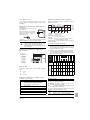
U-5~18MX4XPQ
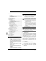
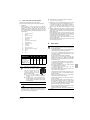
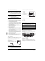
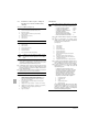
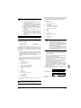
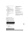
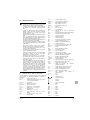
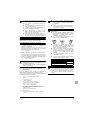
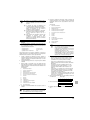
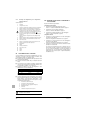
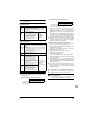
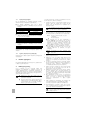
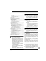
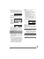
CONTENTS
Page
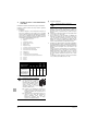
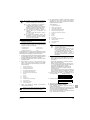
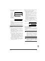
The refrigerant charge of the system must be less than
100 kg. This means that in case the calculated refrigerant
charge is equal to or more than 95 kg you must divide your
multiple outdoor system into smaller independent systems,
each containing less than 95 kg refrigerant charge.
1. Introduction................................................................................ 1
1.1.
1.2.
1.3.
1.4.
2.
3.
4.
5.
6.
Combination ................................................................................. 1
Standard supplied accessories .................................................... 2
Optional accessories.................................................................... 2
Technical and Electrical specifications ......................................... 2
For factory charge, refer to the unit name plate.
Main components ...................................................................... 2
Selection of location .................................................................. 3
Inspecting and handling the unit................................................ 4
Unpacking and placing the unit ................................................. 4
Refrigerant piping ...................................................................... 4
6.1.
6.2.
6.3.
6.4.
6.5.
6.6.
The refrigerant R410A requires strict cautions for keeping
the system clean, dry and tight.
Installation tools ........................................................................... 5
Selection of piping material .......................................................... 5
Pipe connection............................................................................ 5
Connecting the refrigerant piping ................................................. 5
Protection against contamination when installing pipes............... 7
Example of connection................................................................. 8
7. Leak test and vacuum drying .................................................. 10
8. Field wiring .............................................................................. 10
8.1.
8.2.
8.3.
8.4.
8.5.
8.6.
8.7.
Internal wiring – Parts table........................................................ 11
Optional parts cool/heat selector................................................ 11
Power circuit and cable requirements ........................................ 12
General cautions ........................................................................ 12
System examples ....................................................................... 13
Leading power line and transmission line .................................. 13
Field line connection: transmission wiring and
cool/heat selection ..................................................................... 13
8.8. Field line connection: power wiring ............................................ 14
8.9. Wiring example for wiring inside unit.......................................... 15
12.1.
12.2.
12.3.
12.4.
Service precautions.................................................................... 22
Checks before initial start-up...................................................... 23
Field setting................................................................................ 23
Test operation............................................................................. 25
13. Service mode operation .......................................................... 27
14. Caution for refrigerant leaks .................................................... 27
15. Disposal requirements............................................................. 28
READ THIS MANUAL ATTENTIVELY BEFORE STARTING
UP THE UNIT. DO NOT THROW IT AWAY. KEEP IT IN
YOUR FILES FOR FUTURE REFERENCE.
IMPROPER INSTALLATION OR ATTACHMENT OF
EQUIPMENT OR ACCESSORIES COULD RESULT IN
ELECTRIC SHOCK, SHORT-CIRCUIT, LEAKS, FIRE OR
OTHER DAMAGE TO THE EQUIPMENT. BE SURE ONLY
TO USE ACCESSORIES MADE BY PANASONIC WHICH
ARE SPECIFICALLY DESIGNED FOR USE WITH THE
EQUIPMENT AND HAVE THEM INSTALLED BY A
PROFESSIONAL.
PANASONIC EQUIPMENT IS DESIGNED FOR
COMFORT APPLICATIONS. FOR USE IN OTHER
APPLICATIONS, PLEASE CONTACT YOUR LOCAL
PANASONIC DEALER.
IF UNSURE OF INSTALLATION PROCEDURES OR USE,
ALWAYS CONTACT YOUR DEALER FOR ADVICE AND
INFORMATION.
Clean and dry
Foreign materials (including mineral oils such as
SUNISO oil or moisture) should be prevented from
getting mixed into the system.
■
Tight
R410A does not contain any chlorine, does not
destroy the ozone layer, and does not reduce the
earth's protection against harmful ultraviolet radiation.
R410A can contribute slightly to the greenhouse
effect if it is released. Therefore we should take
special attention to check the tightness of the
installation.
Since design pressure is 4.0 MPa or 40 bar (for R407C
units: 3.3 MPa or 33 bar), pipes of larger wall thickness
may be required. The wall thickness of piping must be
carefully selected, refer to paragraph "6.2. Selection of
piping material" on page 5 for more details.
Precautions when adding R410A............................................... 16
Stop valve operation procedure ................................................. 16
How to check how many units are connected ............................ 16
Additional refrigerant charge ...................................................... 17
Checks after adding refrigerant .................................................. 22
12. Before operation ...................................................................... 22
■
Read "6. Refrigerant piping" on page 4 carefully and follow
these procedures correctly.
9. Pipe insulation ......................................................................... 15
10. Checking of unit and installation conditions ............................ 15
11. Charging refrigerant ................................................................ 16
11.1.
11.2.
11.3.
11.4.
11.5.
Installation manual
Urban Multi air conditioner
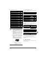
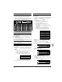
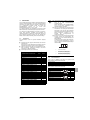
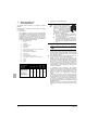
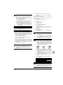
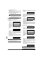
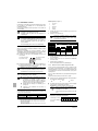
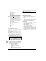
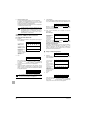
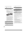
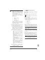
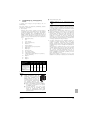
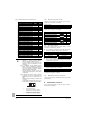
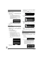
1.
INTRODUCTION
This installation manual concerns Urban Multi units of the Panasonic
U-MX4XPQ series. These units are designed for outdoor installation
and used for cooling and heat pump applications. The U-MX4XPQ
series can be combined from 7 main units and has nominal cooling
capacities ranging from 14.0 to 147 kW and nominal heating
capacities ranging from 16.0 to 170 kW.
The U-MX4XPQ units can be combined with Panasonic Urban Multi
indoor units for air conditioning purposes, and suitable for R410A.
The present installation manual describes the procedures for
unpacking, installing and connecting the U-MX4XPQ units.
Installation of the indoor units is not described in this manual. Always
refer to the installation manual supplied with these units for their
installation.
1.1.
Combination
The indoor units can be installed in the following range.
■
Always use appropriate indoor units compatible with R410A.
To learn which models of indoor units are compatible with
R410A, refer to the product catalogs.
■
Pay attention when connecting outdoor units in multi
combination. U-MX3XPQ(A) units are NOT compatible with
U-MX4XPQ units.
THIS AIR CONDITIONER COMES UNDER THE TERM
"APPLIANCES NOT ACCESSIBLE TO THE GENERAL
PUBLIC".
Installation manual
1
U-5~18MX4XPQ
Urban Multi air conditioner
4PW28163-1C
■
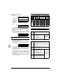
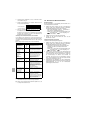
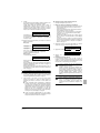
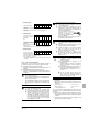
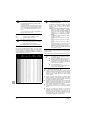
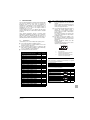
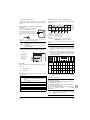
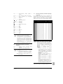
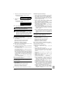
1.2.
Total capacity/quantity of indoor units
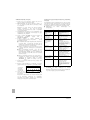
Standard combination of outdoor units
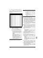
Standard supplied accessories
Total
Total
capacity of quantity of
indoor units indoor units
See location 1 in figure 24 for reference to where following
accessories are supplied with the unit.
Installation manual
Operation manual
Additional refrigerant charge label
U-5MX4
(a)
62,5~162,5
12
U-8MX4
(a)
100~260
20
U-10MX4
(a)
125~325
25
U-12MX4
(a)
150~390
30
U-14MX4
(a)
175~455
35
U-16MX4
(a)
200~520
40
U-18MX4
(a)
225~585
45
See location 2 in figure 24 for reference to where following
accessories are supplied with the unit.
1
1
250~650
40
U-22MX4
= U-10MX4 + U-12MX4
275~715
44
5~10 Hp
48
12~18 Hp
300~780
U-26MX4
= U-8MX4 + U-18MX4
325~845
52
U-28MX4
= U-10MX4 + U-18MX4
350~910
56
U-30MX4
= U-12MX4 + U-18MX4
375~975
60
U-32MX4
= U-14MX4 + U-18MX4
400~1040
64
Quantity
5~18 Hp
= U-8MX4 + U-12MX4
= U-12MX4 + U-12MX4
Gas side accessory pipe
Item
Unit type
U-20MX4
U-24MX4
1
1
1
1
Liquid side accessory pipe
Item
Unit type
Quantity
5~18 Hp
1
5~10, 14, 16 Hp
1
12, 18 Hp
1
U-34MX4
= U-16MX4 + U-18MX4
U-36MX4
= U-18MX4 + U-18MX4
450~1170
64
U-38MX4
= U-18MX4 + U-12MX4 + U-12MX4
475~1235
61
U-40MX4
= U-10MX4 + U-12MX4 + U-12MX4
500~1300
64
U-42MX4
= U-12MX4 + U-12MX4 + U-12MX4
525~1365
64
To install the above outdoor units, the following optional parts are
also required.
U-44MX4
= U-8MX4 + U-18MX4 + U-18MX4
550~1430
64
■
U-46MX4
= U-10MX4 + U-18MX4 + U-18MX4
575~1495
64
U-48MX4
= U-12MX4 + U-18MX4 + U-18MX4
600~1560
64
Refnet header
Refnet joint
U-50MX4
= U-14MX4 + U-18MX4 + U-18MX4
625~1625
64
CZ-P29HK12Q
CZ-P20BK12Q
U-52MX4
= U-16MX4 + U-18MX4 + U-18MX4
650~1690
64
CZ-P64HK12Q
CZ-P29BK12Q
U-54MX4
= U-18MX4 + U-18MX4 + U-18MX4
675~1755
64
CZ-P75HK12Q
425~1105
64
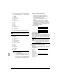
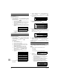
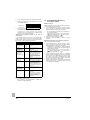
1.3.
Optional accessories
Refrigerant branching kit (for R410A only: Always use an
appropriate kit dedicated for your system.)
CZ-P64BK12Q
(a) = main unit
CZ-P75BK12Q
■
NOTE
■
■
■
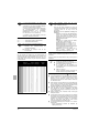
The table above shows the possible total capacity
and number of possible indoor units when
configured in a standard combination.
Refer to the service manual for more details when
using a configuration other than a standard
combination.
If the total capacity of the connected indoor units
exceeds the capacity of the outdoor unit, cooling
and heating performance may drop when running
the indoor units.
Refer to the section on performance characteristics in the Engineering Data Book for details.
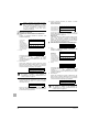
There are restrictions on the refrigerant pipe
connection order between outdoor units during
installation in case of a multiple outdoor unit
system.
Install according to the following restrictions.
The capacities of outdoor units A, B, and C must
fulfill the following restriction conditions: A≥B≥C.
A
1 2
U-5~18MX4XPQ
Urban Multi air conditioner
4PW28163-1C
B
C
3
1
To indoor units
2
Outdoor unit multi connection piping kit (first
branch)
3
Outdoor unit multi connection piping kit
(second branch)
Outdoor unit multi connection piping kit (For R410A only: Always
use an appropriate kit dedicated for your system.)
Number of outdoor units connected
■
2
3
CZ-32PJ4PQ
CZ-48PJ4PQ
Pipe size reducer (For R410A only: Always use an appropriate
kit dedicated for your system.)
U-24~54MX4
CZ-P75BK12Q
CZ-P75HK12Q
To select an optimum refrigerant branching kit, refer to "6. Refrigerant
piping" on page 4.
1.4.
Technical and Electrical specifications
Refer to the Engineering Data Book for the complete list of
specifications.
2.
MAIN
COMPONENTS
For main components and function of the main components, refer to
the Engineering Data Book.
Installation manual
2
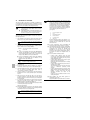
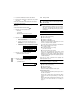
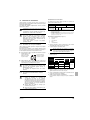
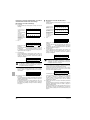
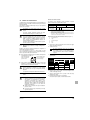
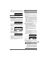
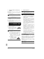
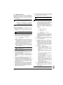
3.
SELECTION
OF LOCATION
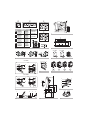
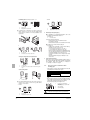
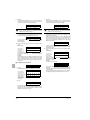
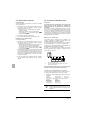
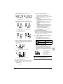
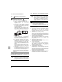
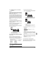
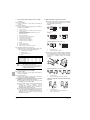
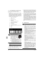
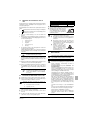
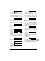
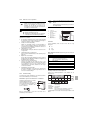
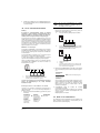
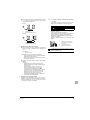
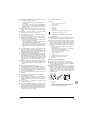
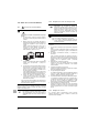
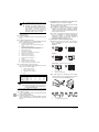
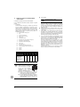
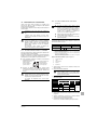
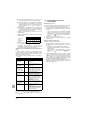
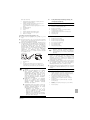
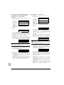
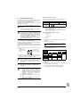
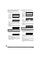
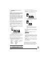
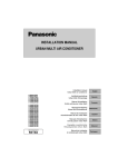
■
This unit, both indoor and outdoor, is suitable for installation in a
commercial and light industrial environment. If installed as a household appliance it could cause electromagnetic interference, in which
case the user may be required to take adequate measures.
■
Make sure to provide for adequate measures in order
to prevent that the outdoor unit be used as a shelter
by small animals.
■
Small animals making contact with electrical parts can
cause malfunctions, smoke or fire. Please instruct the
customer to keep the area around the unit clean.
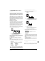
The equipment described in this manual may cause
electronic noise generated from radio-frequency
energy. The equipment complies to specifications that
are designed to provide reasonable protection against
such interference. However, there is no guarantee that
interference will not occur in a particular installation.
It is therefore recommended to install the equipment
and electric wires keeping proper distances away from
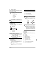
stereo equipment, personal computers, etc...
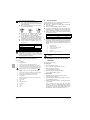
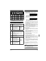
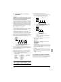
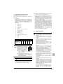
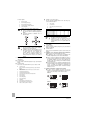
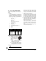
(See figure 2).
1
Personal computer or radio
2
Fuse
Obtain the customer's permission before installing.
3
Earth leakage breaker
The inverter units should be installed in a location that meets the
following requirements:
4
Remote controller
5
Cool/heat selector
1
6
Indoor unit
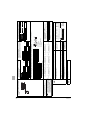
The foundation is strong enough to support the weight of the unit
and the floor is flat to prevent vibration and noise generation.
In places with weak reception, keep distances of 3 m
or more to avoid electromagnetic disturbance of other
equipment and use conduit tubes for power and
transmission lines.
If not, the unit may fall over and cause damage or
injury.
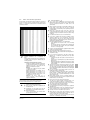
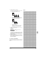
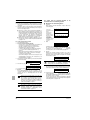
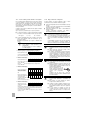
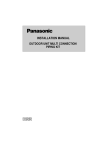
2
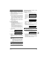
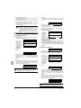
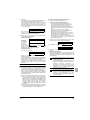
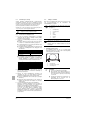
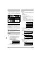
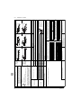
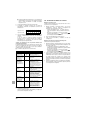
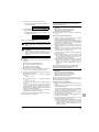
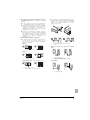
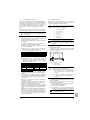
The space around the unit is adequate for servicing and the
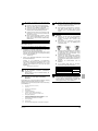
minimum space for air inlet and air outlet is available. (Refer to
figure 1 and choose one of the possibilities).
ABCD
■
In heavy snowfall areas, select an installation site
where snow will not affect the operation of the unit.
■
The refrigerant R410A itself is nontoxic, nonflammable
and is safe. If the refrigerant should leak however, its
concentration may exceed the allowable limit
depending on room size. Due to this, it could be
necessary to take measures against leakage. Refer to
the chapter "14. Caution for refrigerant leaks" on
page 27.
■
Do not install in the following locations.
• Locations where sulfurous acids and other
corrosive gases may be present in the atmosphere.
Copper piping and soldered joints may corrode,
causing refrigerant to leak.
• Locations where a mineral oil mist, spray or vapour
may be present in the atmosphere.
Plastic parts may deteriorate and fall off or causing
water leakage.
• Locations where equipment that produces electromagnetic waves is found.
The electromagnetic waves may cause the control
system to malfunction, preventing normal
operation.
• Locations where flammable gases may leak, where
thinner, gasoline, and other volatile substances are
handled, or where carbon dust and other
incendiary substances are found in the
atmosphere.
Leaked gas may accumulate around the unit,
causing an explosion.
■
When installing, take strong winds, typhoons or
earthquakes into account.
Improper installation may result in fall over of the unit.
Sides along the installation site with obstacles
Suction side
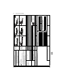
■ In case of an installation site where sides A+B+C+D have
obstacles, the wall heights of sides A+C have no impact on
service space dimensions. Refer to figure 1 for impact of wall
heights of sides B+D on service space dimensions.
■ In case of an installation site where only the sides A+B have
obstacles, the wall heights have no influence on any
indicated service space dimensions.
The service space dimensions in figure 1 are
based on cooling operation at 35°C.
NOTE
3
Make sure that there is no danger of fire due to leakage of
inflammable gas.
4
Ensure that water cannot cause any damage to the location in
case it drips out the unit (e.g. in case of a blocked drain pipe).
5
The piping length between the outdoor unit and the indoor unit
may not exceed the allowable piping length. (Refer to
"6.6. Example of connection" on page 8)
6
Select the location of the unit in such a way that neither the
discharged air nor the sound generated by the unit disturbs
anyone.
7
Make sure that the air inlet and outlet of the unit are not
positioned towards the main wind direction. Frontal wind will
disturb the operation of the unit. If necessary, use a windscreen
to block the wind.
8
Do not install or operate the unit on locations where air contains
high levels of salt, like e.g. in the vicinity of oceans. (Refer for
further information to the engineering databook).
9
During installation, avoid the possibility that anybody can climb
on the unit or place objects on the unit.
Falls may result in injury.
10
When installing the unit in a small room, take measures in order
to keep the refrigerant concentration from exceeding allowable
safety limits in the event of a refrigerant leak.
Excessive refrigerant concentrations in a closed room
can lead to oxygen deficiency.
Installation manual
3
U-5~18MX4XPQ
Urban Multi air conditioner
4PW28163-1C
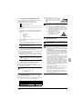
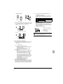
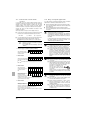
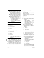
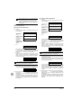
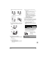
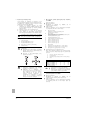
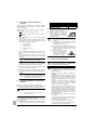
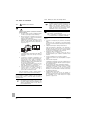
INSPECTING
AND HANDLING THE UNIT
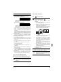
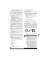
■
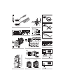
At delivery, the package should be checked and any damage should
be reported immediately to the carrier claims agent.
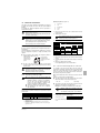
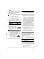
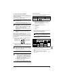
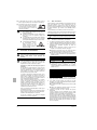
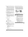
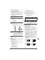
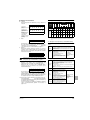
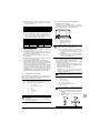
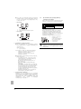
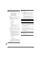
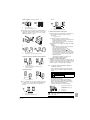
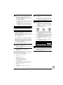
Fasten the unit in place using four
foundation bolts M12. It is best to screw in
the foundation bolts until their length
remains 20 mm above the foundation
surface.
20 mm
4.
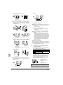
When handling the unit, take into account the following:
■
Prepare a water drainage channel around the
foundation to drain waste water from around the unit.
Keep the unit upright in order to avoid compressor
damage.
■
If the unit is to be installed on a roof, check the
strength of the roof and its drainage facilities first.
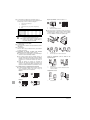
2
Choose on beforehand the path along which the unit is to be
brought in.
■
3
Bring the unit as close as possible to its final installation position
in its original package to prevent damage during transport. (See
figure 4)
If the unit is to be installed on a frame, install the
waterproofing board within a distance of 150 mm
under the unit in order to prevent infiltration of water
coming from under the unit.
■
When installed in a corrosive
environment, use a nut with
plastic washer (1) to protect the
nut tightening part from rust.
1
Fragile, handle the unit with care.
1
4
Packaging material
2
Opening (large)
3
Belt sling
4
Opening (small) (40x45)
5
Protector
1
6.
Always use protectors to prevent belt damage and pay attention
to the position of the unit's centre of gravity.
NOTE
5
Use a belt sling of ≤20 mm wide that adequately
bears the weight of the unit.
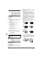
If a forklift is to be used, preferably transport the unit with pallet
first, then pass the forklift arms through the large rectangular
openings on the bottom of the unit. (See figure 5)
5.1 From the moment you use a forklift to move the unit to its final
position, lift the unit under the pallet.
5.2 Once at final position, unpack the unit and pass the forklift arms
through the large rectangular openings on the bottom of the unit.
NOTE
5.
Use filler cloth on the forklift arms to prevent
damaging the unit. If the paint on the bottom
frame peels off, the anti corrosion effect may
decrease.
UNPACKING
AND PLACING THE UNIT
■
Remove the four screws fixing the unit to the pallet.
■
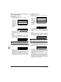
Make sure the unit is installed level on a sufficiently strong base
to prevent vibration and noise.
Do not use stands to only support the corners. (See
figure 7)
X
Not allowed (except for U-5MX4)
PIPING
O
Allowed (units: mm)
■
The height of the foundation must at least be 150 mm from the
floor.
■
The unit must be installed on a solid longitudinal foundation
(steelbeam frame or concrete) as indicated in figure 3.
Model
Use R410A to add refrigerant.
All field piping must be installed by a licensed refrigeration
technician and must comply with relevant local and
national regulations.
Caution to be taken when brazing refrigerant piping
Do not use flux when brazing copper-to-copper refrigerant
piping. (Particularly for the HFC refrigerant piping)
Therefore, use the phosphor copper brazing filler metal
(BCuP) which does not require flux.
Flux has extremely harmful influence on refrigerant piping
systems. For instance, if the chlorine based flux is used, it
will cause pipe corrosion or, in particular, if the flux
contains fluorine, it will damage the refrigerant oil.
Be sure to perform a nitrogen blow when brazing. Brazing
without performing nitrogen replacement or releasing
nitrogen into the piping will create large quantities of
oxidized film on the inside of the pipes, adversely affecting
valves and compressors in the refrigerating system and
preventing normal operation.
After completing the installation work, check that the
refrigerant gas does not leak.
Toxic gas may be produced if the refrigerant gas leaks into
the room and comes in contact with a source of fire.
In the event of a leak, do not touch the leaked refrigerant
directly. Frostbite may be caused.
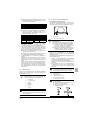
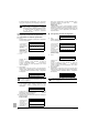
Make sure the base under the unit is larger than the 765 mm of
the unit depth. (See figure 3)
U-5MX4
Do not insert fingers, rods or other objects into the air
inlet or outlet. When the fan is rotating at high speed, it
will cause injury.
Ventilate the area immediately in the event of a leak.
■
■
REFRIGERANT
Lift the unit preferably with a crane and 2 belts of at least 8 m
long. (See figure 4)
A
B
635
497
U-8~12MX4
930
792
U-14~18MX4
1240
1102
Support the unit with a foundation of 67 mm wide or more. (The
support leg of the unit is 67 mm wide, see figure 3).
U-5~18MX4XPQ
Urban Multi air conditioner
4PW28163-1C
Installation manual
4
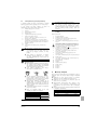
6.1.
Installation tools
6.3.
Make sure to use installation tools (gauge manifold charge hose,
etc.) that are exclusively used for R410A installations to withstand the
pressure and to prevent foreign materials (e.g. mineral oils such as
SUNISO and moisture) from mixing into the system.
(The screw specifications differ for R410A and R407C.)
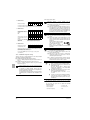
Pipe connection
Be sure to perform a nitrogen blow when brazing and to read the
paragraph "Caution to be taken when brazing refrigerant piping" on
page 4 first.
The pressure regulator for the nitrogen released when
doing the brazing should be set to 0.02 MPa or less.
(See figure 10)
NOTE
Use a 2-stage vacuum pump with a non-return valve which can
evacuate to –100.7 kPa (5 Torr, –755 mm Hg).
Make sure the pump oil does not flow oppositely into
the system while the pump is not working.
NOTE
6.2.
1.
2.
Selection of piping material
Foreign materials inside pipes (including oils for fabrication)
must be 30 mg/10 m or less.
1
Refrigerant piping
2
Location to be brazed
3
Nitrogen
4
Taping
5
Manual valve
6
Regulator
7
Nitrogen
Use the following material specification for refrigerant piping:
■ Size: determine the proper size referring to chapter
"6.6. Example of connection" on page 8.
Do not use anti-oxidants when brazing the pipe joints.
■ Construction material: phosphoric acid deoxidized seamless
copper for refrigerant.
■ Temper grade: use piping with temper grade in function of the
pipe diameter as listed in the table below.
Pipe Ø
Temper grade of piping material
≤15.9
O
≥19.1
1/2H
Residue can clog pipes and break equipment.
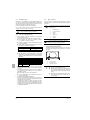
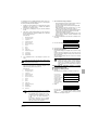
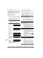
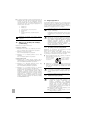
6.4.
1
Connecting the refrigerant piping
Front connection or side connection
Installation of refrigerant piping is possible as front connection or
side connection (when taken out from the bottom) as shown in
the figure.
O = Annealed
1/2H = Half hard
■ The pipe thickness of the refrigerant piping should comply
with relevant local and national regulations. The minimal pipe
thickness for R410A piping must be in accordance with the
table below.
3.
4.
Pipe Ø
Minimal thickness
t (mm)
Pipe Ø
Minimal thickness
t (mm)
6.4
0.80
22.2
0.80
9.5
0.80
28.6
0.99
1
Left-side connection
12.7
0.80
34.9
1.21
2
Front connection
15.9
0.99
41.3
1.43
3
Right-side connection
19.1
0.80
Make sure to use the particular branches of piping that have
been selected referring to chapter "6.6. Example of connection"
on page 8.
In case the required pipe sizes (inch sizes) are not available, it is
also allowed to use other diameters (mm sizes), taken the
following into account:
■ select the pipe size nearest to the required size.
■ use the suitable adapters for the change-over from inch to
mm pipes (field supply).
5.
NOTE
2
3
Precautions when knocking out knock holes
■
Be sure to avoid damaging the casing
■
After knocking out the holes, we recommend you
remove the burrs and paint the edges and areas
around the edges using the repair paint to prevent
rusting.
■
When passing electrical wiring through the knock
holes, wrap the wiring with protective tape to
prevent damage.
Precautions when selecting branch piping
When the equivalent pipe length between outdoor and indoor
units is 90 m or more, the size of the main pipes (both gas side
and liquid side) must be increased.
Depending on the length of the piping, the capacity may drop,
but even in such a case it is possible to increase the size of the
main pipes. Refer to page 9. If the recommended pipe size is not
available, stick to the original pipe diameter (which may result in
a small capacity decrease).
Installation manual
5
1
U-5~18MX4XPQ
Urban Multi air conditioner
4PW28163-1C
2
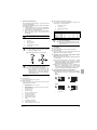
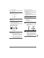
Removing the pinched piping
■
When connecting refrigerant piping to the outdoor unit, first
remove the pinched piping.
Removing of the pinched piping must be carried out according to
the following procedure:
1.
Connect a charge hose to the service port of the liquid side
stop valve and to the service port of the gas side stop valve.
Remove the gas from the pinched piping.
When all the gas is removed from the pinched piping,
dissolve the brazing using a burner and remove the
pinched piping.
2.
3.
Processing the gas side accessory pipe (2)
Only in case of connecting at lateral side, cut the gas side
accessory pipe (2) as shown in figure 11.
1
Gas side accessory pipe
2
Cutting location
3
Gas side piping (field supply)
4
Base
Unit type
5 Hp
8 Hp
10 Hp
12 Hp
14~18 Hp
Any gas remaining inside the stop valve may blow off
the pinched piping, causing damage or injury.
See figure 6.
NOTE
(mm)
(mm)
(mm)
(mm)
(mm)
A
B
C
D
166
156
156
150
150
16
17
23
29
29
199
188
192
192
192
246
247
247
247
251
■
When connecting the piping on site, be sure to
use the accessory piping.
■
Make sure the onsite piping does not come into
contact with other piping, the bottom frame or side
panels of the unit.
1
Service port
2
Gas side stop valve
3
Liquid side stop valve
4
Point of melting the brazing metal
5
Pinched piping
4
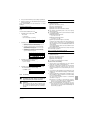
Outdoor units installed in a multiple outdoor unit system:
U-20~54MX4
Precautions when connecting field piping.
■
Front connection:
Remove the stop valve cover to connect. (See figure 8)
■
Bottom connection:
Remove the knock holes on the bottom frame and route the
piping under the bottom frame. (See figure 8)
■
Perform brazing at the gas stop valve before
brazing at the liquid stop valve.
■
Add brazing material as shown in the figure.
4.1 Precautions when connecting piping between outdoor
units (multiple outdoor unit system)
■ The 5 Hp unit type cannot be used as an independent unit in
a multi system.
■ To connect the piping between outdoor units, an optional
multi connection piping kit CZ-32+48PJ4PQ is always
required. When installing the piping, follow the instructions in
the installation manual that comes with the kit.
3
■
Be sure to use the supplied accessory pipes
when carrying out piping work in the field.
■
Be sure that the field installed piping does not
touch other pipes, the bottom panel or side
panel. Especially for the bottom and side
connection, be sure to protect the piping with
suitable insulation, to prevent it from coming into
contact with the casing.
■ Only proceed with piping work after considering the
limitations on installing listed here and in the chapter
"6.4. Connecting the refrigerant piping" on page 5, always
referring to the installation manual delivered with the kit.
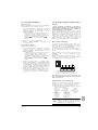
4.2 Possible installation patterns and configurations
■ The piping between the outdoor units must be routed level or
slightly upward to avoid the risk of oil retention into the piping
side.
Pattern 1
One outdoor unit installed: In case of U-5~18MX4
(See figure 8)
■
Front connection:
Remove the stop valve cover to connect.
■
Bottom connection:
Remove the knock holes on the bottom frame and route the
piping under the bottom frame.
A
Front connection
Remove the stop valve cover to connect.
B
Bottom connection:
Remove the knock holes on the bottom frame and route the piping
under the bottom frame
1
Gas side stop valve
2
Liquid side stop valve
3
Service port for adding refrigerant
4
Gas side accessory pipe (1)
5
Gas side accessory pipe (2)
6
Liquid side accessory pipe (1)
7
Liquid side accessory pipe (2)
8
Brazing
9
Gas side piping (field supply)
10
Liquid side piping (field supply)
11
Punch the knockout holes (use a hammer)
U-5~18MX4XPQ
Urban Multi air conditioner
4PW28163-1C
1
1
1
To indoor unit
Pattern 2
1
1
1
To indoor unit
Installation manual
6
Prohibited patterns : change to pattern 1 or 2.
If ≥2 m
≥200 mm
-
1
1
1
2
1
2
2
≤2 m
≥2 m
2
To indoor unit
Piping between outdoor units
1
2
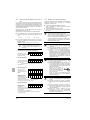
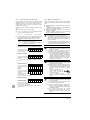
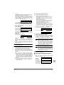
■ To avoid the risk of oil retention to the outmost outdoor unit,
always connect the stop valve and the piping between
outdoor units as shown in the 4 correct possibilities of the
figure below.
5
To indoor unit
Piping between outdoor units
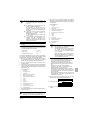
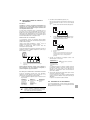
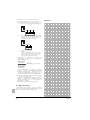
Branching the refrigerant piping
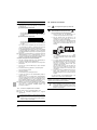
■ For installation of the refrigerant branching kit, refer to the
installation manual delivered with the kit.
(See figure 13)
1
Horizontal surface
Follow the conditions listed below:
- Mount the refnet joint so that it branches either
horizontally or vertically.
- Mount the refnet header so that it branches horizontally.
■ Installation of the multi connection piping kit
(See figure 17)
- Install the joints horizontally, so that the caution label (1)
attached to the joint comes to the top.
Do not tilt the joint more than 15° (see view A).
Do not install the joint vertically (see view B).
- Make sure that the total length of the piping connected to
the joint is absolute straight for more than 500 mm. Only
if a straight field piping of more than 120 mm is
connected, more than 500 mm of straight section can be
ensured.
- Improper installation may lead to malfunction of the
outdoor unit.
Prohibited patterns change to pattern 1 or 2.
1
1
2
1
2
2
2
2
To indoor unit
Oil collects to the outmost outdoor unit.
Change to configuration as in figures below
6
1
Make sure to perform the piping installation within the range of
the maximum allowable pipe length, allowable level difference
and allowable length after branching as indicated in
"6.6. Example of connection" on page 8.
1
2
1
2
Piping length restrictions
2
To indoor unit
Oil collects to the outmost outdoor unit when the system
stops.
6.5.
-
Correct configuration
Protection against contamination when
installing pipes
Take measures to prevent foreign materials like moisture and
contamination from mixing into the system.
≥200 mm
Installation period
More than a month
Less than a month
Regardless of the period
1
1
1
To indoor unit
■ If the piping length between the outdoor units exceeds 2 m,
create a rise of 200 mm or more in the gas line within a
length of 2 m from the kit.
- If ≤2 m
-
Great caution is needed when passing copper tubes through
walls.
Block all gaps in the holes for passing out piping and wiring
using sealing material (field supply). (The capacity of the unit
will drop and small animals may enter the machine.)
Example: passing piping out through the front
1
1
2
1
2
Installation manual
7
≤2 m
Protection method
Pinch the pipe
Pinch or tape the pipe
2
1
Plug the areas marked with "
".
(When the piping is routed from the
front panel.)
2
Gas side piping
3
Liquid side piping
3
After all the piping has been connected, make sure there is
no gas leak. Use nitrogen to perform a gas leak check.
To indoor unit
Piping between outdoor units
U-5~18MX4XPQ
Urban Multi air conditioner
4PW28163-1C
U-5~18MX4XPQ
Urban Multi air conditioner
4PW28163-1C
A
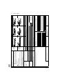
h
1
b
A
B
h
i
1
2
b
c
j
i
B
C
2
3
c
d
j
C
D
k
3
d
H3
4
e
l
k
D
E
4
5
e
f
m
l
E
F
5
6
f
g
n
m
F
G
6
g
G
n
7 H2
7 H2
8
p
H1
8
p
H1
1
1
a
c
c
a
2
2
d
d
3
3
e
e
A
A
b
b
H3
f
4
4
f
g
g
5
5
i
i
h
h
6
6
B
B
j
j
7
7
8
8
k
k
H2
H2
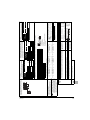
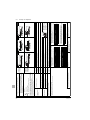
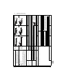
Difference in height between adjacent indoor units (H2)≤15 m
Difference in height between outdoor unit (main) and outdoor unit (sub) (H3)≤5 m
Difference in
height
Difference in
height
Between indoor and indoor units
Between outdoor and outdoor units
Example of downstream indoor units
c
2
2
a
d
d
3
3
e
e
4
4
5
5
f
f
H3
6
6
g
g
h
7 H2
h
7 H2
8
8
i
i
H1
H1
r
s
t
r≤10 m (Approximate length:
max. 13 m)
s≤10 m (Approximate length:
max: 13 m)
t≤10 m (Approximate length:
max: 13 m)
Refrigerant branch kit name
CZ-P20BK12Q
CZ-P29BK12Q
CZ-P64BK12Q
CZ-P75BK12Q
Refrigerant branch kit name
CZ-P64HK12Q (Max. 8 branch)
CZ-P64HK12Q (Max. 8 branch)(a)
CZ-P75HK12Q (Max. 8 branch)
Branch kit name
CZ-32PJ4PQ
CZ-48PJ4PQ
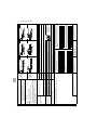
[Example]
in case of header branch pipe;
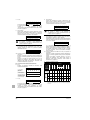
indoor units 1+2+3+4+5+6+7+8
Number of outdoor units
2
3
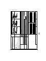
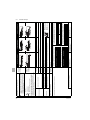
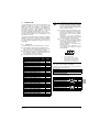
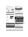
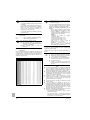
• Choose from the following table in accordance with the number of outdoor units.
How to choose an outdoor multi connection piping kit (needed if the outdoor
unit capacity type is U-20MX4 or more.)
(a) See note 2 on next page
Indoor capacity type (kW)
<290
290≤x<640
≥640
• Choose from the following table in accordance with the total capacity of all the indoor
units connected below the header branch pipe.
• Note: 250 type cannot be connected below the header branch pipe.
[Example]
in case of line branch pipe B; indoor units 7+8,
in case of header branch pipe; indoor units
1+2+3+4+5+6
Refrigerant branch kit name
CZ-P20BK12Q
CZ-P29BK12Q
CZ-P64BK12Q
CZ-P75BK12Q
[Example]
in case of line branch pipe C; indoor units
3+4+5+6+7+8
Indoor capacity type (kW)
<200
200≤x<290
290≤x<640
≥640
• For line branch pipes other than the first branch, select the proper branch kit model
based on the total capacity index.
Outdoor unit capacity type
U-5MX4
U-8+10MX4
U-12~18MX4 + U-20+22MX4
U-24~54MX4
[Example] unit 8: i≤40 m
How to select the header branch pipe
[Example] unit 6: b+h≤40 m, unit 8: i+k≤40 m
• When using line branch pipe at the first branch counted from the outdoor unit side.
Choose from the following table in accordance with the capacity of the outdoor unit.
How to select the line branch pipe
[Example] unit 8: b+c+d+e+f+g+p≤40 m
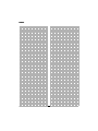
Pipe length from first refrigerant branch kit (either line branch pipe or header branch pipe) to indoor unit ≤40 m (See note 1 on next page)
Difference in height between outdoor and indoor units (H1)≤50 m (≤40 m if outdoor unit is located in a lower
position).
Between outdoor and indoor units
Actual pipe length
Piping length from outdoor branch to outdoor unit ≤10 m. Approximate length: max. 13 m
Difference in
height
Refrigerant branch kits can only be used with R410A.
1
c
Total piping length from outdoor unit* to all indoor units ≤1000 m
Actual pipe length
Refrigerant branch kit selection
b
1
[Example] unit 8: a+i≤165 m
b
a
Total extension
length
[Example] unit 6: a+b+h≤120 m, unit 8: a+i+k≤165 m
H1
H1
Branch with header branch pipe
Equivalent pipe length between outdoor(*) and indoor units ≤190 m (Assume equivalent pipe length of line branch pipe to be 0.5 m and of the header branch pipe to be
1.0 m. (for calculation purposes))
[Example] unit 8: a+b+c+d+e+f+g+p≤165 m
Pipe length between outdoor(*) and indoor units ≤165 m
a
a
Branch with line branch pipe and header branch
pipe
Equivalent length
Actual pipe length
Outdoor units
installed in a
multiple outdoor
unit system
(U-20~54MX4)
One outdoor unit
installed
(U-5~18MX4)
Branch with line branch pipe
Between outdoor branch and outdoor unit (Only for
U-20MX4 or more)
Allowable length after the branch
Allowable height
Maximum allowable length
Between outdoor and indoor units
Install the joint part ( part in the figure) of the outdoor unit multi connection piping kit
horizontally with attention to the installation restrictions described in "connecting the
refrigerant piping".
(*) If the system capacity is U-20MX4 or more, re-read to the first outdoor branch as
seen from the indoor unit.
outdoor multi connection piping kit
header branch pipe
line branch pipe
indoor unit
• Use the outdoor unit multi connection piping kit that is sold separately as an option
(CZ-32PJ4PQ+CZ-48PJ4PQ) for the multi installation of outdoor units. Selection
method is as shown in the right table.
• Do not use the outdoor unit multi connection piping kit (CZ-32PJ2PQ+CZ-48PJ2PQ)
that are sold separately as an option of the M-type series and do not use T-joints.
Example of connection
(Connection of 8 indoor units Heat pump system)
6.6.
Example of connection
Installation manual
8
Installation manual
9
U-5~18MX4XPQ
Urban Multi air conditioner
4PW28163-1C
E
A
C
B
B
B
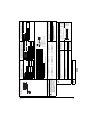
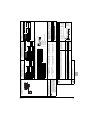
Note 2
Note 1
The refrigerant charge of the system must be less
than 100 kg. This means that in case the calculated
refrigerant charge is equal to or more than 95 kg you
must divide your multiple outdoor system into smaller
independent systems, each containing less than
95 kg refrigerant charge.
For factory charge, refer to the unit name plate.
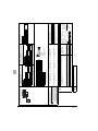
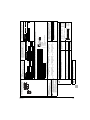
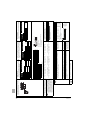
How to calculate the additional refrigerant to be charged
Additional refrigerant to be charged R (kg)
R should be rounded off in units of 0.1 kg
D
Pipe size selection
For an outdoor unit multi installation (U-20~54MX4), select the
pipe size in accordance with the following figure.
Piping size (outer diameter) (mm)
Gas pipe
Liquid pipe
Ø15.9
Ø19.1
Ø9.5
Ø22.2
Ø12.7
Ø28.6
Ø15.9
Ø34.9
Ø19.1
Ø41.3
Indoor or outdoor unit
total capacity (kW)
<150
150≤x<200
200≤x<290
290≤x<420
420≤x<640
640≤x<920
≥920
Piping size (outer diameter) (mm)
Gas pipe
Liquid pipe
Ø15.9
Ø19.1
Ø9.5
Ø22.2
Ø12.7
Ø28.6
Ø15.9
Ø34.9
Ø19.1
Ø41.3
• Choose from the following table in accordance with the total capacity of
all the indoor units connected below this.
• Do not let the connection piping exceed the refrigerant piping size
chosen by general system model name.
D. Piping between refrigerant branch kits
Indoor capacity type
20~50
63~125
200
250
(
(
Total length (m) of liquid
piping size at Ø12.7
Total length (m) of liquid
piping size at Ø22.2
)
)
x0.12+
x0.37+
(
(
Total length (m) of liquid
piping size at Ø9.5
Total length (m) of liquid
piping size at Ø19.1
)
)
x0.059+
x0.26+
Liquid side
U-5MX4
Ø9.5
—
U-8+10MX4
Ø9.5 ➞ Ø12.7
U-12~16MX4
Ø12.7 ➞ Ø15.9
U-18~24MX4
Ø15.9 ➞ Ø19.1
U-26~54MX4
Ø19.1 ➞ Ø22.2
— Increase is not allowed
(
(
1
2
3
4
5
2
3
Total length (m) of liquid
piping size at Ø6.4
Total length (m) of liquid
piping size at Ø15.9
Indoor unit
4
)
)
First refrigerant branch kit
Increase
Main pipes
Outdoor unit
1
x0.022
5
d: Ø9.5x10 m
e: Ø9.5x10 m
f: Ø9.5x10 m
indoor unit 8:
b+c+d+e+f+g+p≤90 m
increase the pipe size
of b, c, d, e, f, g
a+b*2+c*2+d*2+e*2+f*2+g*2
+h+i+j+k+l+m+n+p≤1000 m
h, i, j....... p≤40 m
The farthest indoor unit 8
The nearest indoor unit 1
(a+b+c+d+e+f+g+p)–(a+h)≤40 m
It is necessary to increase the pipe size between the first branch kit and the final branch kit. (Reducers
must be procured on site.) However, if the pipes are of the same pipe size as the main pipe there is no
need to increase the pipe size.
For calculation of total extension length, the actual length of above pipes must be doubled. (except main
pipe and the pipes that not increase the pipe size)
Indoor unit to the nearest branch kit ≤40 m
The difference between the distance of the outdoor unit to the farthest indoor unit and the distance of the
outdoor unit to the nearest indoor unit ≤40 m
If the pipe size above the refnet header is Ø34.9 or more,
CZ-P75HK12Q is required.
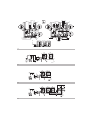
Example drawings
Required conditions
g: Ø6.4x10 m
h: Ø6.4x20 m
i: Ø12.7x10 m
j: Ø6.4x10 m
k: Ø6.4x9 m
Ø15.9 ➞ Ø19.1
Ø19.1 ➞ Ø22.2
2
3
1
a
A
h
1
b
B
i
2
c
C
j
3
d
D
k
4
e
E
l
5
f
F
m
6
g
G
n
7 H2
8
p
H1
1 Outdoor unit
2 Refnet joints
(a~g)
3 Indoor units (1~8)
* If available on the site. Otherwise it can not be increased.
Ø6.4 ➞ Ø9.5
Ø9.5 ➞ Ø12.7
Ø12.7 ➞ Ø15.9
Increase the pipe size as follows
Ø22.2 ➞ Ø25.4*
Ø28.6 ➞ Ø31.8*
Ø34.9 ➞ Ø38.1*
R = [30x0.26]+[10x0.18]+[10x0.12]+[40x0.059]+[49x0.022] = 14.238
⇒ R = 14.2 kg
a: Ø19.1x30 m
b: Ø15.9x10 m
c: Ø9.5x10 m
Example for refrigerant branch using line branch pipe and
header branch pipe for U-34MX4
If the outdoor unit is U-34MX4 and the piping lengths are as below
Allowable length after the first refrigerant branch kit to indoor units is 40 m or less, however it can be extended up to 90 m if all the following conditions are fulfilled.
x0.18+
R=
Ø19.1
Ø22.2
Ø25.4(a)
—
Ø31.8(a)
—
Ø38.1(a)
—
(a) If not available, increase is not allowed
Gas side
U-5MX4
Ø15.9 ➞
U-8MX4
Ø19.1 ➞
U-10MX4
Ø22.2 ➞
U-12+14MX4
Ø28.6
U-16~22MX4
Ø28.6 ➞
U-24MX4
Ø34.9
U-26~34MX4
Ø34.9 ➞
U-36~54MX4
Ø41.3
— Increase is not allowed
Piping size (outer diameter) (mm)
Gas pipe
Liquid pipe
Ø12.7
Ø6.4
Ø15.9
Ø19.1
Ø9.5
Ø22.2
• Pipe size for direct connection to indoor unit must be the same as the
connection size of indoor unit.
E. Piping between refrigerant branch kit and indoor unit
When the equivalent pipe length between outdoor and indoor units is 90 m or more, the size of the main pipes (both gas side and liquid side) must be increased.
Depending on the length of the piping, the capacity lay drop, but even in such a case it is possible to increase the size of the main pipes.
Outdoor unit
capacity type
U-5MX4
U-8MX4
U-10MX4
U-12~16MX4
U-18~22MX4
U-24MX4
U-26~34MX4
U-36~54MX4
• Choose from the following table in accordance with the outdoor unit total
capacity type, connected downstream.
Outdoor unit connection piping size
A,B,C. Piping between outdoor unit and refrigerant branch kit
7.
LEAK
TEST AND VACUUM DRYING
The units were checked for leaks by the manufacturer.
■
Vacuum drying: Use a vacuum pump which can evacuate to
–100.7 kPa (5 Torr, –755 mm Hg)
1.
Evacuate the system from the liquid and gas pipes by using a
vacuum pump for more than 2 hours and bring the system to
–100.7 kPa. After keeping the system under that condition for
more than 1 hour, check if the vacuum gauge rises or not. If it
rises, the system may either contain moisture inside or have
leaks.
2.
Following should be executed if there is a possibility of moisture
remaining inside the pipe (if piping work is carried out during the
raining season or over a long period of time, rainwater may enter
the pipe during work).
After evacuating the system for 2 hours, pressurize the system
to 0.05 MPa (vacuum break) with nitrogen gas and evacuate the
system again using the vacuum pump for 1 hour to –100.7 kPa
(vacuum drying). If the system cannot be evacuated to
–100.7 kPa within 2 hours, repeat the operation of vacuum
break and vacuum drying.
Then, after leaving the system in vacuum for 1 hour, confirm that
the vacuum gauge does not rise.
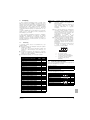
After connecting the field piping, perform the following inspections.
1
Preparations
Referring to figure 27, connect a nitrogen tank, a cooling tank,
and a vacuum pump to the outdoor unit and perform the
airtightness test and the vacuum drying. The stop valve and
valves A and B in figure 27 should be open and closed as shown
in the table below when performing the airtightness test and
vacuum drying.
1
Pressure reducing valve
2
Nitrogen
3
Measuring instrument
4
Tank (siphon system)
5
Vacuum pump
6
Charge hose
7
Service port for adding refrigerant
8
Gas line stop valve
Liquid line stop valve
Outdoor unit
11
To indoor unit
12
Stop valve service port
13
Dotted lines represent on site piping
14
Valve B
15
Valve C
16
Valve A
State
of the valves A and B
and the stop valve
Performing the
airtightness test and
vacuum drying
(Valve A must always be
shut. Otherwise the
refrigerant in the unit will
pour out.)
2
Valve
A
Valve
B
Valve
C
Liquid
side
stop
valve
Close
Open
Open
Close
Gas
side
stop
valve
Close
■
See "11.2. Stop valve operation
procedure" on page 16 for details on handling the
stop valve.
■
To prevent entry of any contamination and to
prevent insufficient pressure resistance, always
use the special tools dedicated for working with
R410A refrigerant.
Airtightness test:
Make sure to use nitrogen gas.
Pressurize the liquid and gas pipes to 4.0 MPa (40 bar) (do not
pressurize more than 4.0 MPa (40 bar)). If the pressure does not
drop within 24 hours, the system passes the test. If the pressure
drops, check where the nitrogen leaks from.
U-5~18MX4XPQ
Urban Multi air conditioner
4PW28163-1C
WIRING
The field wiring must be carried out in accordance with the
wiring diagrams and the instructions given below.
Make sure to perform airtightness test
and vacuum drying using the service
ports of the stop valves of the liquid
side and of the gas side. (For the
service port location, refer to the
"Caution" label attached on the front
panel of the outdoor unit.)
NOTE
FIELD
All field wiring and components must be installed by a
licensed electrician and must comply with relevant local
and national regulations.
Airtightness test and vacuum drying
NOTE
■
8.
9
10
Be sure to use a dedicated power circuit. Never use a
power supply shared by another appliance. This can lead
to electric shock or fire.
Be sure to install an earth leakage circuit breaker.
(Because this unit uses an inverter, install an earth
leakage circuit breaker that is capable of handling high
harmonics in order to prevent malfunctioning of the earth
leakage breaker itself.)
Do not operate until refrigerant piping work is completed.
(If operated before completion of the piping work, the
compressor may break down.)
Never remove a thermistor, sensor, etc., when connecting
power wiring and transmission wiring.
(If operated without thermistor, sensor, etc., the
compressor may break down.)
This product's reversed phase protection detector only
works when the product started up.
The reversed phase protection detector is designed to stop
the product in the event of an abnormalities when the
product is started up.
Replace two of the three phases (L1, L2, and L3) during
reverse-phase protection circuit operation.
Reversed phase detection is not performed while the
product is operating.
If there exists the possibility of reversed phase after an
momentary black out and the power goes on and off while
the product is operating, attach a reversed phase
protection circuit locally. Running the product in reversed
phase can break the compressor and other parts.
Means for disconnection must be incorporated in the field
wiring in accordance with the wiring rules.
(An all-pole disconnection switch must be available on the
unit.)
Installation manual
10
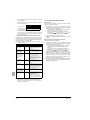
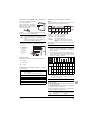
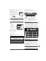
8.1.
Internal wiring – Parts table
L1,L2,L3 ................ Live
Refer to the wiring diagram sticker on the unit. The abbreviations
used are listed below:
N............................ Neutral
.............. Field wiring
A1P~7P..................Printed circuit board
................. Terminal strip
BS1~5 ....................Push button switch (mode, set, return, test,
reset)
......................... Connector
........................ Terminal
C1,C63,C66 ...........Capacitor
......................... Protective earth (screw)
DS1,2 .....................Dip switch
BLK........................ Black
E1HC~3HC ............Crankcase heater
BLU ....................... Blue
F1U ........................Fuse (250 V, 8 A, B) (A4P) (A8P)
BRN....................... Brown
F1U,2U...................Fuse (250 V, 3.15 A, T) (A1P)
GRN ...................... Green
F5U ........................Field fuse
GRY....................... Grey
F400U ....................Fuse (250 V, 6.3 A, T) (A2P)
H1P~8P..................Light emitting diode (service monitor - orange)
ORG ...................... Orange
PNK ....................... Pink
HAP........................Pilot lamp (service monitor - green)
RED....................... Red
K1...........................Magnetic relay
WHT ...................... White
K2...........................Magnetic contactor (MIC)
YLW....................... Yellow
K2M,3M..................Magnetic contactor (M2C,M3C)
K1R,R ....................Magnetic relay (K2M,K3M)
NOTE
K3R~5R .................Magnetic relay (Y1S~Y3S)
(1) This wiring diagram only applies to the outdoor unit.
(4) When using the option adaptor, refer to the
installation manual.
K6R~9R .................Magnetic relay (E1HC~E3HC)
L1R ........................Reactor
(5) Refer to the installation manual, for connection
wiring to indoor-outdoor transmission F1-F2, outdoormulti transmission Q1-Q2 and on how to use BS1~BS5
and DS1, DS2 switch.
M1C~3C.................Motor (compressor)
M1F,2F ...................Motor (fan)
PS ..........................Switching power supply (A1P,A3P)
(6) Do not operate the unit by short-circuiting
protection device S1PH.
Q1DI.......................Earth leakage breaker (field supply)
Q1RP .....................Phase reversal detection circuit
R1T ........................Thermistor (fin) (A2P)
8.2.
R1T ........................Thermistor (air) (A1P)
Optional parts cool/heat selector
S1S........................ Selector switch (fan, cool/heat)
R2T ........................Thermistor (suction)
S2S........................ Selector switch (cool/heat)
R4T ........................Thermistor (coil-deicer)
NOTE
R5T ........................Thermistor (coil-outlet)
R6T ........................Thermistor (liquid-pipe receiver)
■
Use copper conductors only.
■
For connection wiring to the central remote
controller, refer to the installation manual of the
central remote controller.
■
Use insulated wire for the power cord.
R7T ........................Thermistor (accumulator)
R10 ........................Resistor (current sensor) (A4P) (A8P)
R31T~33T ..............Thermistor (discharge) (M1C~M3C)
R50,59 ...................Resistor
R95 ........................Resistor (current limiting)
S1NPH ...................Pressure sensor (high)
S1NPL....................Pressure sensor (low)
S1PH,3PH..............Pressure switch (high)
T1A ........................Current sensor (A6P,A7P)
SD1 ........................Safety devices input
V1R ........................Power module (A4P,A8P)
V1R,V2R ................Power module (A3P)
X1A,X4A ................Connector (M1F,M2F)
X1M........................Terminal strip (power supply)
X1M........................Terminal strip (control) (A1P)
X1M........................Terminal strip (A5P)
Y1E,2E...................Expansion
subcool)
valve
(electronic
type)
(main,
Y1S ........................Solenoid valve (hotgas bypass)
Y2S ........................Solenoid valve (oil return)
Y3S ........................Solenoid valve (4 way valve)
Z1C-7C ..................Noise filter (ferrite core)
Z1F.........................Noise filter (with surge absorber)
Installation manual
11
U-5~18MX4XPQ
Urban Multi air conditioner
4PW28163-1C
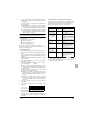
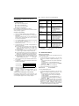
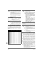
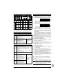
8.3.
Power circuit and cable requirements
A power circuit (see table below) must be provided for connection of
the unit. This circuit must be protected with the required safety
devices, i.e. a main switch, a slow blow fuse on each phase and an
earth leakage breaker.
U-5MX4
U-8MX4
U-10MX4
U-12MX4
U-14MX4
U-16MX4
U-18MX4
U-20MX4
U-22MX4
U-24MX4
U-26MX4
U-28MX4
U-30MX4
U-32MX4
U-34MX4
U-36MX4
U-38MX4
U-40MX4
U-42MX4
U-44MX4
U-46MX4
U-48MX4
U-50MX4
U-52MX4
U-54MX4
NOTE
Phase and
frequency
Voltage
Minimum
circuit
ampere
3 N~50 Hz
3 N~50 Hz
3 N~50 Hz
3 N~50 Hz
3 N~50 Hz
3 N~50 Hz
3 N~50 Hz
3 N~50 Hz
3 N~50 Hz
3 N~50 Hz
3 N~50 Hz
3 N~50 Hz
3 N~50 Hz
3 N~50 Hz
3 N~50 Hz
3 N~50 Hz
3 N~50 Hz
3 N~50 Hz
3 N~50 Hz
3 N~50 Hz
3 N~50 Hz
3 N~50 Hz
3 N~50 Hz
3 N~50 Hz
3 N~50 Hz
400 V
400 V
400 V
400 V
400 V
400 V
400 V
400 V
400 V
400 V
400 V
400 V
400 V
400 V
400 V
400 V
400 V
400 V
400 V
400 V
400 V
400 V
400 V
400 V
400 V
11.9 A
18.5 A
21.6 A
22.7 A
31.5 A
31.5 A
32.5 A
41.2 A
44.3 A
50.4 A
51.0 A
54.1 A
55.2 A
63.0 A
64.0 A
65.0 A
73.7 A
81.5 A
82.5 A
83.5 A
86.6 A
87.7 A
96.5 A
96.5 A
97.5 A
Recommended
fuses
16 A
25 A
25 A
25 A
40 A
40 A
40 A
50 A
50 A
50 A
63 A
63 A
63 A
80 A
80 A
80 A
100 A
100 A
100 A
100 A
100 A
100 A
125 A
125 A
125 A
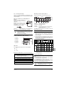
8.4.
■
Up to 3 units can be connected by crossover power source
wiring between outdoor units. However, units of smaller capacity
must be connected downstream. For details, refer to the
technical data.
■
When connecting several units in Urban Multi combination, the
power supply of each outdoor unit can also be connected
separately. Refer to the field wiring on the engineering data book
for further details.
■
Make sure to connect the power source wire to the power
source terminal block and to clamp it as shown in figure 21 and
described in chapter "8.8. Field line connection: power wiring"
on page 14.
■
For conditional connections, refer to the Technical Data.
■
As this unit is equipped with an inverter, installing a phase
advancing capacitor not only will deteriorate power factor
improvement effect, but also may cause capacitor abnormal
heating accident due to high-frequency waves. Therefore, never
install a phase advancing capacitor.
■
Keep power imbalance within 2% of the supply rating.
• Large imbalance will shorten the life of the smoothing
capacitor.
• As a protective measure, the product will stop operating and
an error indication will be made, when power imbalance
exceeds 4% of the supply rating.
■
Follow the "electrical wiring diagram" supplied with the unit when
carrying out any electrical wiring.
■
Only proceed with wiring work after all power is shut off.
■
Always ground wires. (In accordance with national regulations of
the pertinent country.)
■
Do not connect the ground wire to gas pipes, sewage pipes,
lightning rods, or telephone ground wires. This may cause
electric shock.
• Combustion gas pipes: can explode or catch fire if there is a
gas leak.
• Sewage pipes: no grounding effect is possible if hard plastic
piping is used.
• Telephone ground wires and lightning rods: dangerous when
struck by lightning due to abnormal rise in electrical potential
in the grounding.
This unit uses an inverter, and therefore generates noise, which
will have to be reduced to avoid interfering with other devices.
The outer casing of the product may take on an electrical charge
due to leaked electrical current, which will have to be discharged
with the grounding.
Be sure to install an earth leakage breaker. (One that can
handle high-frequency electrical noise.)
(This unit uses an inverter, which means that an earth leakage
breaker capable of handling high-frequency electrical noise
must be used in order to prevent malfunctioning of the earth
leakage breaker itself.)
Earth leakage breakers that are especially designed for
protecting ground-faults must be used in conjunction with main
switch and fuse for use with wiring.
Never connect the power supply in reversed phase.
The unit can not operate normally in reversed phase. If you
connect in reversed phase, replace two of the three phases.
This unit has a reverse phase detection circuit. (If it is activated,
only operate the unit after correcting the wiring.)
Power supply wires must be attached securely.
If the power supply has a missing or wrong N-phase, equipment
will break down.
Make sure that all wiring is secure, the specified wires are used,
and no external forces act on the terminal connection or wires.
Improper connections or installation may result in fire.
Transmission line
section
0.75~1.25 mm2
0.75~1.25 mm2
0.75~1.25 mm2
0.75~1.25 mm2
0.75~1.25 mm2
0.75~1.25 mm2
0.75~1.25 mm2
0.75~1.25 mm2
0.75~1.25 mm2
0.75~1.25 mm2
0.75~1.25 mm2
0.75~1.25 mm2
0.75~1.25 mm2
0.75~1.25 mm2
0.75~1.25 mm2
0.75~1.25 mm2
0.75~1.25 mm2
0.75~1.25 mm2
0.75~1.25 mm2
0.75~1.25 mm2
0.75~1.25 mm2
0.75~1.25 mm2
0.75~1.25 mm2
0.75~1.25 mm2
0.75~1.25 mm2
The above table indicates power specifications for
standard combinations. See "1. Introduction" on
page 1.
If using anything other than the above combinations in
a multiple outdoor unit system, calculate using the
following procedure.
Calculate the recommended fuse capacity
Calculate, by adding the minimum circuit ampere
of each used unit (according to the table above),
multiply the result by 1.1 and select the next
higher recommended fuse capacity.
Example
Combining the U-30MX4 by using the U-8MX4,
U-10MX4, and U-12MX4.
Minimum circuit ampere of the U-8MX4 = 18.5 A
Minimum circuit ampere of the U-12MX4 = 21.6 A
Minimum circuit ampere of the U-12MX4 = 22.7 A
Accordingly, the minimum circuit ampere of the
U-30MX4=18.5+21.6+22.7= 62.8 A
Multiplying
the
above
result
by
1.1
(62.8 x 1.1)=69.08 A, so the recommended fuse
capacity would be 80 A.
When using residual current operated circuit breakers, be sure to use
a high-speed type 300 mA rated residual operating current.
Be sure to install a main switch for the complete system.
NOTE
■
Select the power supply cable in accordance with
relevant local and national regulations.
■
Wire size must comply with the applicable local
and national code.
■
Specifications for local wiring power cord and
branch wiring are in compliance with IEC60245.
■
WIRE TYPE H05VV(*)
*Only in protected pipes (use H07RN-F when
protected pipes are not used).
U-5~18MX4XPQ
Urban Multi air conditioner
4PW28163-1C
General cautions
■
■
■
■
■
■
■
■
■
■
When wiring the power supply and connecting the remote
controller wiring and transmission wiring, position the wires so
that the control box lid can be securely fastened.
Improper positioning of the control box lid may result in electric
shocks, fire, or overheating of the terminals.
Installation manual
12
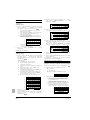
8.5.
System examples
(See figure 15)
1
Field power supply
2
Main switch
3
Earth leakage breaker
4
Outdoor unit
5
Indoor unit
6
Remote controller
■
Use a power wire pipe for the power wiring.
■
Outside the unit, make sure the weak low voltage
electric wiring (i.e. for the remote control, between
units, etc.) and the high voltage electric wiring do not
pass near each other, keeping them at least 50 mm
apart. Proximity may cause electrical interference,
malfunctions, and breakage.
■
Be sure to connect the power wiring to the power
wiring terminal block and secure it as described under
"Field line connection: power wiring" on page 14.
■
Inter-unit wiring should be secured as described in
"8.7. Field line connection: transmission wiring and
cool/heat selection" on page 13.
• Secure the wiring with the accessory clamps so
that it does not touch the piping and no external
force can be applied to the terminal.
• Make sure the wiring and the electric box lid do not
stick up above the structure, and close the cover
firmly.
Power supply wiring (sheathed cable) (230 V)
Transmission wiring (sheathed cable) (16 V)
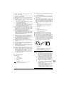
8.6.
Leading power line and transmission line
■
Be sure to let the power line and the transmission line pass
through a conduit hole.
■
Lead the power line from the upper hole on the left side plate,
from the front position of the main unit (through the conduit hole
of the wiring mounting plate) or from a knock out hole to be
made in the unit's bottom plate. (See figure 18)
1
Electric wiring diagram. Printed on the back of the electric box lid.
2
Power wiring and ground wiring between outdoor units (inside
conduit)
(When the wiring is routed out through the lateral panel.)
3
Transmission wiring
4
Pipe opening
5
Conduit
6
Power wiring and ground wiring
7
Cut off the shaded zones before use.
8
Through cover
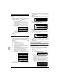
8.7.
In case of U-5~18MX4 (See figure 19)
Precautions when knocking out knockout holes
■
To punch a knockout hole, hit on it with a hammer.
■
After knocking out the holes, we recommend you paint the
edges and areas around the edges using the repair paint to
prevent rusting.
■
1
Cool/heat selector
2
Outdoor unit PC board (A1P)
3
Take care of the polarity
4
Use the conductor of sheathed wire (2 wire) (no polarity)
5
Terminal board (field supply)
6
Indoor unit
7
Outdoor unit
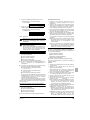
In case of U-20~54MX4 (See figure 20)
When passing electrical wiring through the knockout holes,
remove any burrs from the knockout hole edges. Wrap the wiring
with protective tape in order to prevent damage to the wires, put
the wires through field supplied protective wire conduits at that
location, or install suitable field supplied wire nipples or rubber
bushings into the knockout holes.
1
Unit A (Master unit)
2
Unit B (Slave unit)
3
Unit C (Slave unit)
4
To slave unit(s)
5
To indoor unit
6
To outdoor unit
7
To cool/heat selector
NOTE
1
2
3
1
Knockout hole
2
Burr
3
If there are any possibilities that small animals enter the system
through the knockout holes, plug the holes with packing materials
(to be prepared on-site).
Installation manual
13
Field line connection: transmission wiring and
cool/heat selection
U-5MX4 cannot install the multi unit transmission
wiring. Run will not be successful if the wiring is
connected to Q1-Q2 (TO MULTI UNIT) terminal.
■
The interconnecting wiring between the outdoor units in the
same piping system must be connected to the Q1/Q2 (Out Multi)
terminals. Connecting the wires to the F1/F2 (Out-Out) terminals
results in system malfunction.
■
The wiring for the other systems must be connected to the F1/F2
(Out-Out) terminals of the P-board in the outdoor unit to which
the interconnecting wiring for the indoor units is connected.
■
The base unit is the outdoor unit to which the interconnecting
wiring for the indoor units is connected.
U-5~18MX4XPQ
Urban Multi air conditioner
4PW28163-1C
Fixing transmission wiring (See figure 23)
Inside switchbox
■
Be sure to keep the power line and transmission line
apart from each other.
■
Be careful about polarity of the transmission line.
1
Heating/cooling switching remote control cord (when a heating/
cooling switch remote control (optional) is connected) (ABC) (not
for U-5~18MX4)
■
Make sure that the transmission line is clamped as
shown in figure 23.
2
Fix to the indicated plastic brackets using field supplied clamping
material.
■
Check that wiring lines do not make contact with
refrigerant piping.
3
Wiring between the units (Outdoor - outdoor) (F1+F2 right)
■
4
Wiring between the units (Indoor - outdoor) (F1+F2 left)
Firmly close the lid and arrange the electrical wires so
as to prevent the lid or other parts from coming loose.
5
Wiring for multi connection (only for U-20~54MX4) (Q1+Q2)
■
6
Plastic bracket
When you do not use a wire conduit, be sure to
protect the wires with vinyl tubes etc, to prevent the
edge of the knock-out hole from cutting the wires.
Outside unit
■
Be sure to follow the limits below. If the unit-to-unit
cables are beyond these limits, it may result in
malfunction of transmission.
- Maximum wiring length:
1000 m
- Total wiring length:
2000 m
- Maximum interunit wiring length
30 m
between outdoor units:
- Transmission wiring to cool/heat
500 m
selector:
- Maximum number of branches:
16
■
Maximum number of outdoor units connectable: 10.
■
Up to 16 branches are possible for unit-to unit cabling.
No branching is allowed after branching.
(See figure 16)
1
Outdoor unit
2
Indoor unit
3
Main line
4
Branch line 1
5
Branch line 2
6
Branch line 3
7
No branch is allowed after branch
8
Central remote controller (etc...)
A
Transmission wiring between outdoor unit and indoor
unit(s)
B
Transmission wiring between outdoor units
■
Never connect the power supply to transmission
wiring terminal block. Otherwise the entire system
may break down.
■
Never connect 400 V to the terminal block of the
interconnecting wiring. Doing so will break the entire
system.
- The wiring from the indoor units must be
connected to the F1/F2 (In-Out) terminals on the
PC board in the outdoor unit.
- After installing the interconnecting wires inside the
unit, wrap them along with the on-site refrigerant
pipes using finishing tape, as shown in figure 12.
1
Liquid pipe
2
Gas pipe
3
Insulator
4
Interconnecting wiring
5
Finishing tape
For the above wiring, always use vinyl cords with 0.75
to 1.25 mm2 sheath or cables (2-core wires). (3-core
wire cables are allowable for the cooler/heater
changeover remote controller only.)
U-5~18MX4XPQ
Urban Multi air conditioner
4PW28163-1C
Sequential start
The outdoor unit PC board (A1P) is factory set at "Sequential start
available".
Setting the cool/heat operation
1
Performing cool/heat setting with the remote controller
connected to the indoor unit.
Keep the cool/heat selector switch (DS1) on the outdoor unit PC
board at the factory setting position IN/D UNIT. (See figure 22)
1
2
Remote controller
Performing cool/heat setting with the cool/heat selector.
Connect the cool/heat selector remote controller (optional) to the
A/B/C terminals and set the cool/heat selector switch (DS1) on
the outdoor unit PC board (A1P) to OUT/D UNIT. (See figure 25)
1
Cool/heat selector
For low-noise operation, it is necessary to get the optional
'External control adaptor for outdoor unit' (DTA104A61/62).
For details, see the installation manual attached to the
adaptor.
8.8.
Field line connection: power wiring
The power cord must be clamped to the plastic bracket using field
supplied clamp material.
The green and yellow striped wrapped wires must be used for
grounding. (See figure 21)
1
Power supply (400 V, 3 N~50 Hz)
2
Fuse
3
Earth leakage breaker
4
Grounding wire
5
Power supply terminal block
6
Connect each power wire
RED to L1, WHT to L2, BLK to L3 and BLU to N
7
Ground wire (GRN/YLW)
8
Clamp the power wire to the plastic bracket using a field supplied
clamp to prevent external force being applied to the terminal.
9
Clamp (field supply)
10
Cup washer
11
When connecting the earth wire, it is recommended to perform
curling.
■
Do not allow the ground wires to contact the
compressor lead wires. If the wires contact each
other, adverse effects may occur to other units.
■
When connecting or disconnecting a power supply
cord, make sure that the current-carrying conductors
become taut before the earthing conductor.
Installation manual
14
9.
Precautions when laying power wiring
■
Do not connect wiring of different thicknesses to the
power terminal block. (Slack in the power wiring may
cause abnormal heat.)
■
When connecting wiring which is the same thickness,
do as shown in the figure below.
■
■
■
Make sure to insulate the connection piping and refrigerant
branch kits entirely.
■
Be sure to insulate liquid and gas piping (for all units).
■
Use heat resistant polyethylene foam which can withstand a
temperature of 70°C for liquid side piping and polyethylene foam
which can withstand a temperature of 120°C for gas side piping.
■
Reinforce the insulation on the refrigerant piping according to
the installation environment.
Use an appropriate screwdriver for tightening the
terminal screws. A screwdriver with a small head will
strip the head and make proper tightening impossible.
Over-tightening the terminal screws may break them.
■
See the table below for tightening torque for the
terminal screws.
INSULATION
After finishing the leak test and vacuum drying, the piping must be
insulated. Take into account the following points:
For wiring, use the designated power wire and
connect firmly, then secure to prevent outside
pressure being exerted on the terminal board.
■
PIPE
Ambient temperature
Humidity
≤30°C
75% to 80% RH
Minimum thickness
15 mm
>30°C
≥80 RH
20 mm
Condensation might form on the surface of the insulation.
■
If there is a possibility that condensation on the stop valve might
drip down into the indoor unit through gaps in the insulation and
piping because the outdoor unit is located higher than the indoor
unit this must be prevented by sealing up the connections. See
figure 9.
Tightening torque (N•m)
M8 (Power terminal block)
M8 (Ground)
M3 (Inter-unit wiring terminal block)
5.5~7.3
0.8~0.97
Recommendations when connecting the ground
When pulling the ground wire out, wire it so that it comes
through the cut out section of the cup washer. (An
improper ground connection may prevent a good ground
from being achieved.) (See figure 21)
8.9.
Wiring example for wiring inside unit
1
Gas line stop valve
2
Liquid line stop valve
3
Service port for adding refrigerant
4
Sealing up treatment
5
Insulation
6
Indoor -outdoor interconnection piping
Be sure to insulate local pipes, as touching them can
cause burns.
10. CHECKING
OF UNIT AND INSTALLATION
CONDITIONS
See figure 26.
1
Electric wiring
2
Wiring between units
3
Clamp to the electric box with field supplied clamps.
The piping work
4
When routing out the power/ground wires from the right side:
1
5
When routing the remote control cord and inter-unit wiring, secure
clearance of 50 mm or more from the power wiring. Ensure that
the power wiring does not contact any heated sections (
).
Make sure piping size is correct.
See "6.2. Selection of piping material" on page 5.
2
Make sure insulation work is done.
6
Clamp to the back of the column support with field supplied
clamps.
7
When routing out the inter-unit wirings from the opening for piping:
8
When routing out the power/ground wires from the front:
9
When routing out the ground wires from the left side:
10
Grounding wire
11
When wiring, pay attention not to detach the acoustic insulators
from the compressor.
12
Power supply
13
Fuse
14
Earth leakage breaker
15
Ground wire
16
Unit A
17
Unit B
18
Unit C
Installation manual
15
Be sure to check the following:
See "9. Pipe insulation" on page 15.
3
Make sure there is no faulty refrigerant piping.
See "6. Refrigerant piping" on page 4.
The electrical work
1
Make sure there is no faulty power wiring or loose nuts.
See "8. Field wiring" on page 10.
2
Make sure there is no faulty transmission wiring or loose nuts.
See "8. Field wiring" on page 10.
3
Make sure the insulation resistance of the main power circuit is
not deteriorated.
Using a megatester for 500 V, check that the insulation
resistance of 2 MΩ or more is attained by applying a voltage of
500 V DC between the power terminals and earth. Never use
the megatester for the transmission wiring (between outdoor
and indoor unit, outdoor and COOL/HEAT selector, etc.).
U-5~18MX4XPQ
Urban Multi air conditioner
4PW28163-1C
11. CHARGING
Opening stop valve (See figure 14)
REFRIGERANT
The outdoor unit is factory charged, but depending on the length of
the piping when installed, the outdoor unit may require additional
charging.
For charging the additional refrigerant follow the procedure as
described in this chapter.
Refrigerant cannot be charged until all field wiring and field
piping has been completed.
Refrigerant may only be charged after performing the leak
test and the vacuum drying.
The refrigerant charge of the system must be less than
100 kg. This means that in case the calculated refrigerant
charge is equal to or more than 95 kg you must divide your
multiple outdoor system into smaller independent systems,
each containing less than 95 kg refrigerant charge.
1
Service port
2
Cap
3
Hexagon hole
4
Shaft
5
Seal
1.
Remove the cap and turn the valve counterclockwise with the
hexagon wrench.
2.
Turn it until the shaft stops.
Do not apply excessive force to the stop valve. Doing
so may break the valve body, as the valve is not a
backseat type. Always use the special tool.
3.
Make sure to tighten the cap securely. Refer to the table below
Tightening torque N•m (Turn clockwise to close)
For factory charge, refer to the unit name plate.
Shaft
11.1. Precautions when adding R410A
Valve body
Ø9.5
5.4~6.6
Ø12.7
8.1~9.9
Ø15.9
13.5~16.5
6 mm
23.0~27.0
27.0~33.0
8 mm
22.5~27.5
Be sure to charge the specified amount of refrigerant in liquid state to
the liquid pipe.
Since this refrigerant is a mixed refrigerant, adding it in gas form may
cause the refrigerant composition to change, preventing normal
operation.
■
Before charging, check whether the refrigerant cylinder is
equipped with a siphon tube or not.
Charge the liquid
refrigerant with the
cylinder in upright
position.
■
Charge the liquid
refrigerant with the
cylinder in up-side-down
position.
Be sure to use tools exclusively for R410A to ensure required
pressure resistance and to prevent foreign materials from mixing
into the system.
Charging with an unsuitable substance may cause
explosions and accidents, so always make sure that the
appropriate refrigerant (R410A) is charged.
Refrigerant containers must be opened slowly.
■
■
Ø22.2
Ø25.4
Do not open the stop valve until all piping and
electrical steps of "10. Checking of unit and
installation conditions" on page 15 are completed. If
the stop valve is left open without turning on the
power, it may cause refrigerant to build up in the
compressor, leading to insulation degradation.
Always use a charge hose for service port connection.
After tightening the cap, check that no refrigerant
leaks are present.
Gas line stop valve
8
10
(a)
Ø9.5
Ø15.9 Ø19.1
12
14
16
2.
Securely tighten the valve until the shaft contacts the main body
seal.
3.
Make sure to tighten the cap securely.
For the tightening torque, refer to the table above.
11.3. How to check how many units are connected
It is possible to find out how many indoor units are active and
connected by operating the push-button switch on the printed circuit
board (A1P) of the working outdoor unit. In a multiple outdoor unit
system, you can find out how many outdoor units are connected to
the system by using the same procedure.
Follow the 5-step procedure as explained below.
■
The LEDs on the A1P shows the operating status of the outdoor
unit and the number of indoor units that are active.
x
■
w
OFF
c
ON
Blinking
The number of units that are active can be read from the LED
display in the "Monitor Mode" procedure below.
Example: in the following procedure there are 22 units active:
Wherever during this procedure, press the
BS1 MODE button if something becomes unclear.
You will return to setting mode 1 (H1P=
x "OFF").
18
(b)
Ø12.7
Ø25.4(c)
(a) The model U-12MX4 supports field piping of Ø12.7 on the accessory pipe
supplied with the unit.
(b) The model U-18MX4 supports field piping of Ø15.9 on the accessory pipe
supplied with the unit.
(c) The model U-10MX4 supports field piping of Ø22.2 on the accessory pipe
supplied with the unit.
The model U-12~18MX4 supports field piping of Ø28.6 on the accessory pipe
supplied with the unit.
U-5~18MX4XPQ
Urban Multi air conditioner
4PW28163-1C
11.5~13.9
Remove the cap and turn the valve clockwise with the hexagon
wrench.
NOTE
5
18.0~22.0
1.
The sizes of the stop valves connected to the system are as listed in
the table below.
Type
Service port
13.5~16.5
Closing stop valve (See figure 14)
Size of stop valve
Liquid line stop valve
4 mm
Cap (valve lid)
Make sure that all the indoor units connected to the outdoor unit are
active.
11.2. Stop valve operation procedure
■
Hexagonal
wrench
Stop valve size
1
Setting mode 1 (default system status)
H1P H2P H3P H4P H5P H6P H7P
Default status (normal)
x
x w x
x
x
x
Press the BS1 MODE button to switch from setting mode 1 to monitor
mode.
Installation manual
16
2
Follow the procedures below.
Monitor mode
H1P H2P H3P H4P H5P H6P H7P
Default status display
c x
x
x
x
x
x
■
When charging a system, charging over
permissible quantity can cause liquid hammer.
■
Always use protective gloves and protect your eyes
when charging refrigerant.
■
When the refrigerant charging procedure is done or
when pausing, close the valve of the refrigerant tank
immediately. If the tank is left with the valve open, the
amount of refrigerant which is properly charged may
get off point. More refrigerant may be charged by any
remaining pressure after the unit has stopped.
To check the number of indoor units, press the BS2 SET button 5 times
To check the number of outdoor units, press the BS2 SET button 8 times
3
Monitor mode
H1P H2P H3P H4P H5P H6P H7P
Selection status of how many
connected indoor units to
display.
c x
x
x w x w
Electric shock warning
OR
H1P H2P H3P H4P H5P H6P H7P
■
Close the electric box lid before turning on the main
power.
c x
■
Perform the settings on the circuit board (A1P) of the
outdoor unit and check the LED display after the
power is on via the service lid which is in the lid of the
electric box.
Operate switches with an insulated
stick (such as a ball-point pen) to
avoid touching the life parts.
Make sure to re-attach the
inspection cover into the switch box cover after the job
is finished.
Calculate the number of connected indoor units by adding the values of
all (H2P~H7P) blinking (c) leds together.
In this example: 16+4+2=22 units
■
If the power of some units is turned off, the charging
procedure can not be finished properly.
Press the BS1 MODE button to return to step 1, setting mode 1
(H1P= x "OFF").
■
In case of a multiple outdoor system, turn on the
power of all outdoor units.
■
Make sure to turn ON the power 6 hours before
starting the operation. This is necessary to warm the
crankcase by the electric heater.
■
If operation is performed within 12 minutes after the
indoor and outdoor units are turned on, the H2P-led
will be lit and the compressor will not operate.
Selection status of how many
connected outdoor units to
display.
x w x
x
x
Pressing the BS3 RETURN button causes the LED display to show the
data on the number of indoor units that are connected or how many
outdoor units that are connected in a multiple outdoor unit system.
4
the
Monitor mode
H1P H2P H3P H4P H5P H6P H7P
Displaying the number of
connected indoor units
c x c x c c x
32
16
8
4
2
1
11.4. Additional refrigerant charge
There are two ways to charge refrigerant. Use the selected method
following the described procedure below.
■
Adding refrigerant using leak detection function.
Refer to "1 Adding refrigerant using leak detection function" on
page 17
■
Adding refrigerant without using leak detection function.
Refer to "2 Adding refrigerant without using leak detection
function" on page 20
NOTE
■
See "11.2. Stop valve operation procedure" on
page 16 for details on how to handle stop valves.
■
The refrigerant charging port is connected to the
piping inside the unit.
The unit’s internal piping is already factory
charged with refrigerant, so be careful when
connecting the charge hose.
■
After adding the refrigerant, do not forget to close
the lid of the refrigerant charging port.
The tightening torque for the lid is 11.5 to
13.9 N•m.
■
In order to ensure uniform refrigerant distribution,
it may take the compressor ±10 minutes to start
up after the unit has started operation. This is not
a malfunction.
Adding refrigerant using the automatic refrigerant charging
function is recommended.
If refrigerant is added manually, without using the
automatic refrigerant charging function, the refrigerant leak
detection function cannot be used.
The refrigerant leak detection function can be used during
regular inspections or maintenance after installation of the
unit.
1
Adding refrigerant using leak detection function
The automatic refrigerant charging has limits as described
below.
At out of limit, the system can not operate the automatic
refrigerant charging.
Installation manual
17
Outdoor temperature
: 0°C DB~43°C DB
Indoor temperature
: 20°C DB~32°C DB
Total indoor unit capacity
: ≥80%
U-5~18MX4XPQ
Urban Multi air conditioner
4PW28163-1C
To speed up the proces of charging refrigerant for large systems, it is
recommended to first manually charge a portion of the refrigerant
first before performing automatic charging.
1
Calculate how much refrigerant to be added using the formula
explained in the chapter "How to calculate the additional
refrigerant to be charged" on page 9.
2
The amount of pre-charging is 10 kg less than the calculated
amount.
3
Open valve C (valves A and B and the stop valves must be left
closed) and charge the refrigerant in liquid form via the liquid
side stop valve service port.
1.
Start of automatic charging refrigerant
- Open the liquid and gas side stop valves and the service port
stop valve. (Valves A, B and C must be closed.)
- Close all frontpanels except the electric box frontpanel and
turn the power ON.
- Make sure all indoor units are connected, refer to "11.3. How
to check how many units are connected" on page 16.
- If the H2P led is not flashing (in 12 minutes time after turning
on the power), make sure it is displayed as shown in the
"3 Normal system display" on page 21.
If the H2P led is flashing, check the malfunction code on the
remote controller "4 Remote controller malfunction code
display" on page 21.
2.
Press the BS1 MODE button once if the LEDs combination is not
as in the figure below.
(See figure 28)
1
Measuring instrument
2
Tank (siphon system)
3
Charge hose
4
Liquid line stop valve
5
Gas line stop valve
6
Stop valve service port
7
Valve B
8
Valve C
9
Valve A
4.
Hold the BS4 TEST button down for 5 seconds or more.
10
Outdoor unit
5.
11
Refrigerant charge port
12
To indoor unit
13
Interunit piping
14
Refrigerant flow
Charging mode judgement
For automatic charging, the charging must be done in cooling
mode.
However, if the indoor temperature is 20°C DB or lower, in some
cases the unit will first charge in heating mode to increase the
indoor temperature.
The unit will automatically select the cooling mode or heating
mode for charging.
4
H1P H2P H3P H4P H5P H6P H7P
x
3.
x
x
Press the BS4 TEST button once.
w w w w w w w
During charging in heating mode, a person must
manually close valve A before complete charging is
finished. The required amount is the the calculated
amount (see "6.6. Example of connection" on page 8)
minus 10 kg, therefore, the weight must be monitored
constantly.
At least the unit should be charged with its original amount
of refrigerant (refer to the nameplate on the unit), before
starting the automatic charging.
After pre-charging, perform the refrigerant charge operation as
shown below and charge the remaining refrigerant of the
additional charging amount through valve A.
(See figure 29)
1
Measuring instrument
2
Tank (siphon system)
3
Charge hose
4
Liquid line stop valve
5
Gas line stop valve
6
Stop valve service port
7
Valve B
8
Valve C
9
Valve A
10
Outdoor unit
11
Refrigerant charge port
12
Field piping
13
Refrigerant flow
14
Indoor unit
NOTE
x
H1P H2P H3P H4P H5P H6P H7P
If the calculated amount of pre-charging is reached, close
valve C.
5
x w x
For a multi outdoor unit system, it is not required
to connect all charge ports to a refrigerant tank.
The refrigerant will be charged with ±22 kg in
1 hour time at an outdoor temperature of 30°C DB
or with ±6 kg at an outdoor temperature of
0°C DB.
Continue with the automatic charging in cooling
mode OR in heating mode.
■ Charging in heating mode
6.
Start up
Wait while the unit is preparing for charging in heating mode.
H1P H2P H3P H4P H5P H6P H7P
Pressure control
(for the first minute)
x c x
x
x
Start up control
(for the next 2 minutes)
c c x
c c x
x
x
x w x
x w w
Waiting for stable
heating conditions
(for the next ±15
minutes (according to
the system))
7.
x w
Ready
H1P H2P H3P H4P H5P H6P H7P
c c x
x w x w
Press the BS4 TEST button once within 5 minutes.
If the BS4 TEST button is not pushed within 5 minutes, P2 will be
displayed on the remote controller. Refer to "4 Remote controller
malfunction code display" on page 21.
If you need to speed up in case of a multiple
outdoor system, connect the refrigerant tanks to
each outdoor unit as shown in figure 29.
U-5~18MX4XPQ
Urban Multi air conditioner
4PW28163-1C
Installation manual
18
8.
Operation
When the following led display is shown, open valve A and close
the frontpanel. If the frontpanel is left open, the system can not
operate properly during the refrigerant charging.
8.
Operation
When the following led display is shown, open valve A and close
the frontpanel. If the frontpanel is left open, the system can not
operate properly during the refrigerant charging.
H1P H2P H3P H4P H5P H6P H7P
H1P H2P H3P H4P H5P H6P H7P
w c *
w c *
*
*
*
*
* = The state of this led is not important.
When a malfunction occurs, check the display of the
remote controller and refer to "4 Remote controller
malfunction code display" on page 21.
9.
Complete
If the calculated amount of refrigerant minus 10 kg is reached,
close valve A and press the BS3 RETURN button once.
H1P H2P H3P H4P H5P H6P H7P
c c c w w w w
As long as the BS3 RETURN button is not pressed, the system
will remain in heating mode. This can be required to increase the
indoor temperature.
10. Press the BS4 TEST button to perform the temperature range
check
Out of range:
H1P H2P H3P H4P H5P H6P H7P
Out of outdoor
temperture range
w c c c w x
Out of indoor
temperture range
w c c c x w x
x
In these cases, press the BS1 MODE button once and follow the
procedure as "5 Final adjustment of the amount of refrigerant"
on page 22.
In range:
The unit will restart from the charging mode judgement onwards
and the cooling mode will be selected. However, if in the mean
time the temperature has become out of range, heating mode
will be selected again, this is required to increase the indoor
temperature.
■ Charging in cooling mode
6.
x
x
H1P H2P H3P H4P H5P H6P H7P
7.
*
*
When a malfunction occurs, check the display of the
remote controller and refer to "4 Remote controller
malfunction code display" on page 21.
9.
Complete
If the display on the remote controller shows a flashing PE code,
charging is almost finished.
When the unit stops operating, close valve A immediately and
check the leds and check if the P9 code is displayed on the
remote controller. When the charging amount is little, the PE
code may not be displayed, but instead the P9 code will be
displayed immediately.
H1P H2P H3P H4P H5P H6P H7P
w c c w w w w
If it is not as shown above, correct the malfunction (as indicated
in the display of the remote controller) and restart the complete
charging procedure.
10. Press the BS4 TEST button to perform the temperature range
check
Out of range:
H1P H2P H3P H4P H5P H6P H7P
Out of outdoor
temperture range
w c c c w x
Out of indoor
temperture range
w c c c x w x
x
In these cases, press the BS1 MODE button once and follow the
procedure as described in "5 Final adjustment of the amount of
refrigerant" on page 22.
In range:
The state of the leds will show:
w c c w w w w
x w
Start up
Wait while the unit is preparing for charging in cooling mode.
Pressure control
(for the first minute)
x c x
x
x
Start up control
(for the next 2 minutes)
x c x
x c x
x
x
x w x
x w w
Waiting for stable
heating conditions
(for the next ±15
minutes (according to
the system))
*
H1P H2P H3P H4P H5P H6P H7P
H1P H2P H3P H4P H5P H6P H7P
x c x
*
* = The state of this led is not important.
x w
Press the BS1 MODE button once. The procedure is completed.
Record the amount that was added on the additional refrigerant
charge label provided with the unit and attach it on the back side
of the front panel.
Perform the test procedure as described in "In case refrigerant
was added by using the leak detection function" on page 25.
Ready
H1P H2P H3P H4P H5P H6P H7P
c c c x w x w
Press the BS4 TEST button once within 5 minutes.
If the BS4 TEST button is not pushed within 5 minutes, P2 will be
displayed on the remote controller. Refer to "4 Remote controller
malfunction code display" on page 21.
Installation manual
19
U-5~18MX4XPQ
Urban Multi air conditioner
4PW28163-1C
2
Adding refrigerant without using leak detection function
■
Charge with the outdoor unit at standstill
1.
Calculate how much refrigerant to be added using the formula
explained in the chapter "How to calculate the additional
refrigerant to be charged" on page 9.
2.
Continue with the manually charging in cooling
mode OR in heating mode.
■ Charging in heating mode
6.
Open valve C (valves A and B and the stop valves must be left
closed) and charge the required amount of refrigerant through
the liquid side stop valve service port.
■ When the required amount of refrigerant is fully charged,
close valve C. Record the amount of refrigerant that was
added on the additional refrigerant charge label provided
with the unit and attach it on the back side of the front panel.
Perform the test procedure as described in "In case
refrigerant was added without using the leak detection
function (pre-charging, charging in heating mode)" on
page 26.
H1P H2P H3P H4P H5P H6P H7P
Charge with operating outdoor unit
Charge the refrigerant through valve A.
1.
Start of charging refrigerant manually
- Open the liquid and gas side stop valves and the service port
stop valve. (Valves A, B and C must be closed.)
- Close all frontpanels except the electric box frontpanel and
turn the power ON.
- Make sure all indoor units are connected, refer to "11.3. How
to check how many units are connected" on page 16.
- If the H2P led is not flashing (in 12 minutes time after turning
on the power), make sure it is displayed as shown below.
If the H2P led is flashing, check the malfunction code on the
remote controller "4 Remote controller malfunction code
display" on page 21.
2.
7.
x
3.
x w x
x
x
x
x c x
x
x
Start up control
(for the next 2 minutes)
c c x
c c x
x
x
x w x
x w w
x w
Ready
H1P H2P H3P H4P H5P H6P H7P
c c x
x w x w
Press the BS4 TEST button once within 5 minutes.
If the BS4 TEST button is not pushed within 5 minutes, P2 will be
displayed on the remote controller. Refer to "4 Remote controller
malfunction code display" on page 21.
8.
Operation
When the following led display is shown, open valve A and close
the frontpanel. If the frontpanel is left open, the system can not
operate properly during the refrigerant charging.
H1P H2P H3P H4P H5P H6P H7P
w c *
*
*
*
*
* = The state of this led is not important.
When a malfunction occurs, check the display of the
remote controller and refer to "4 Remote controller
malfunction code display" on page 21.
Press the BS1 MODE button once if the LEDs combination is not
as in the figure below.
H1P H2P H3P H4P H5P H6P H7P
Pressure control
(for the first minute)
Waiting for stable
heating conditions
(for the next ±15
minutes (according to
the system))
■ When the additional charging is not complete, perform the
procedure explained in the chapter "Charge with operating
outdoor unit" on page 20.
■
Start up
Wait while the unit is preparing for charging in heating mode.
9.
Complete
If the calculated amount of refrigerant minus 10 kg is reached,
close valve A and press the BS3 RETURN button once.
Press the BS4 TEST button once.
H1P H2P H3P H4P H5P H6P H7P
H1P H2P H3P H4P H5P H6P H7P
w w w w w w w
4.
Hold the BS4 TEST button down for 5 seconds or more.
5.
Charging mode judgement
If the indoor temperature is 20°C DB or lower, charging in
cooling mode is not possible in some cases. The unit will
automatically select the cooling mode or heating mode for
charging.
c c c w w w w
10. Press the BS1 MODE button once and the charging is complete.
Record the amount that was added on the additional refrigerant
charge label provided with the unit and attach it on the back side
of the front panel.
Perform the test procedure as described in "In case refrigerant
was added without using the leak detection function (precharging, charging in heating mode)" on page 26.
When charging in cooling mode, the unit will stop
operating when the required amount of refrigerant is
charged.
During charging in heating mode, a person must
manually close valve A when complete charging is
finished. Calculate how much refrigerant to be added
using the formula explained in the chapter "How to
calculate the additional refrigerant to be charged" on
page 9.
For the cooling only models, heating mode can not be
selected. In this case, the led disply will indicate out of
range. Refer to the procedure as described in "5 Final
adjustment of the amount of refrigerant" on page 22.
U-5~18MX4XPQ
Urban Multi air conditioner
4PW28163-1C
Installation manual
20
■ Charging in cooling mode
6.
3
Start up
Wait while the unit is preparing for charging in cooling mode.
x c x
x
x
Start up control
(for the next 2 minutes)
x c x
x c x
x
x
x w x
x w w
Waiting for stable
heating conditions
(for the next ±15
minutes (according to
the system))
7.
Microcomputer
operation
monitor
Mode
Ready
/Error
Indivi- Bulk
Bulk
dual (master) (slave)
Low
noise Demand
Multi
HAP
H1P
H2P
H3P
H4P
H5P
H6P
H7P
H8P
Single outdoor
unit system
c
x
x
w
x
x
x
x
x
Master
unit(a)
c
x
x
w
x
x
x
x
w
c
x
x
x
x
x
x
x
c
c
x
x
x
x
x
x
x
x
x w
Ready
H1P H2P H3P H4P H5P H6P H7P
Multiple Slave
outdoor unit
unit
1(a)
system Slave
unit
2(a)
c c c x w x w
Press the BS4 TEST button once within 5 minutes.
If the BS4 TEST button is not pushed within 5 minutes, P2 will be
displayed on the remote controller. Refer to "4 Remote controller
malfunction code display" on page 21.
8.
Operation
When the following led display is shown, open valve A and close
the frontpanel. If the frontpanel is left open, the system can not
operate properly during the refrigerant charging.
(a) The state of the H8P (multi) LED in a multi-system shows wich unit is the master
unit (w), slave 1 unit (c) or slave 2 unit (x).
Only the master unit is connected to the indoor units with interunit wiring.
4
Remote controller malfunction code display
Remote controller heating mode malfunction codes
Error code
P8
recharge
operation
Close valve A immediately and press the TEST OPERATION
button once.
The operation will restart from the charging mode judgement
onwards.
P2
charge
hold
Close valve A immediately. Check
following items:
- Check if the gas side stop valve is
opened correctly
- Check if the valve of the refrigerant
cylinder is opened
- Check if the air inlet and outlet of the
indoor unit are not obstructed
H1P H2P H3P H4P H5P H6P H7P
w c *
*
*
*
*
* = The state of this led is not important.
When a malfunction occurs, check the display of the
remote controller and refer to "4 Remote controller
malfunction code display" on page 21.
9.
Complete
If the display on the remote controller shows a flashing PE code,
charging is almost finished.
When the unit stops operating, close valve A immediately and
check the leds and check if the P9 code is displayed on the
remote controller.
H1P H2P H3P H4P H5P H6P H7P
w c c w w w w
If it is not as shown above, correct the malfunction (as indicated
in the display of the remote controller) and restart the complete
charging procedure. When the charging amount is little, the PE
code may not be displayed, but instead the P9 code will be
displayed immediately.
10. Press the BS1 MODE button once and the charging is complete.
Record the amount that was added on the additional refrigerant
charge label provided with the unit and attach it on the back side
of the front panel.
Perform the test procedure as described in "In case refrigerant
was added without using the leak detection function (charging in
cooling mode)" on page 25.
Installation manual
21
Cooling/Heating
changeover
LED
display
(Default
status
before
delivery)
H1P H2P H3P H4P H5P H6P H7P
Pressure control
(for the first minute)
Normal system display
After correcting the
abnormality, restart
the automatic
charging procedure
again.
Remote controller cooling mode malfunction codes
Error code
Close valve A and replace the empty cylinder. When renewed,
open valve A (the outdoor unit will not stop operating).
The code on the display shows the unit where a cylinder is to be
PA, PH, PC
renewed:
replace
PA = master unit, PH = slave unit 1, PC = slave unit 2, flashing PA,
cylinder
PH and PC = all units
After recplacing the cylinder, open valve A again and continue the
work.
P8
recharge
operation
Close valve A immediately.
Restart the automatic charging procedure again.
P2
charge
hold
Close valve A immediately. Check
following items:
- Check if the gas side stop valve is
opened correctly
- Check if the valve of the refrigerant
cylinder is opened
- Check if the air inlet and outlet of the
indoor unit are not obstructed
- Check if the indoor temperature is not
lower than 20°C DB
*
abnormal
stop
Close valve A immediately. Confirm the
malfunction code by the remote controller
and correct the abnormality by following
the "Correcting after abnormal completion
of the test operation" on page 26.
After correcting the
abnormality, restart
the automatic
charging procedure
again.
U-5~18MX4XPQ
Urban Multi air conditioner
4PW28163-1C
12. BEFORE
5
Final adjustment of the amount of refrigerant
■
When the unit displays an out of temperature range, the
automatic charging of refrigerant can not be completed.
■ Out of outdoor temperature range
12.1.
OPERATION
Service precautions
H1P H2P H3P H4P H5P H6P H7P
w c c c w x
x
WARNING: ELECTRIC SHOCK
Complete the charging of refrigerant on another time when
the outdoor temperature is warmer than 0°C DB and colder
than 43°C DB.
Caution when
equipment
■ Out of indoor temperature range
Measure the voltage between terminals on the
terminal block for power supply with a tester and
confirm that the power supply is shut off.
In addition, measure the points, as shown in the figure
below, with a tester and confirm that the voltage of the
capacitor in the main circuit is less than 50 V DC.
A2P
A3P
3
To prevent damaging the PC-board, touch a
noncoated metal part to eliminate static electricity
before pulling out or plugging in connectors.
4
The performing of the service to the inverter
equipment must be started after the junction
connectors X1A, X2A, X3A, X4A (X3A and X4A are
for 14~18 unit type only) for the fan motors in the
outdoor unit are been pulled out. Be carefull not to
touch the live parts.
Overcharging judgement procedure
2
Turn on the power to the outdoor unit and all the connected
indoor units.
3
Press the BS1 MODE button once and set the setting model
H1P = OFF.
4
Press and hold the BS4 TEST button down for 5 seconds.
A1P
TP1 TP2
When the temperature has come in range (outdoor = 0~43°C,
indoor = 20~32°C), perform the overcharging judgement
procedure for completion of the refrigerant charging operation.
Close all the front panels except the electric box front panel and
the lid on the side of the electric box.
inverter
2
In this case, perform a test operation (as explained in the
chapter "12.4. Test operation" on page 25) and the unit will work
properly. (The malfunction code U3 will be displayed on the
indoor unit.)
However, the refrigerant leak detection function can not be used
before completing the refrigerant charging operation and the
judgement of the initial amount of refrigerant by performing the
test operation again.
1
to
Do not open the electric box cover for 10 minutes after
the power supply is turned off.
Complete the charging of refrigerant on another time when
the indoor temperature is warmer than 20°C DB and colder
than 32°C DB.
■
service
1
H1P H2P H3P H4P H5P H6P H7P
w c c c x w x
performing
(If a fan rotates due to strong wind, it may store
electricity in the capacitor or in the main circuit and
cause electric shock.)
The system will start operating.
After operating for 40 minutes, the operation will stop
automatically.
After the service is finished, plug the junction
connecter back in. Otherwise the error code E7 will be
displayed on the remote controller and normal
operation will not be performed.
6
After the system has stopped operating, check the display on
the remote controller.
For details refer to the wiring diagram labeled on the back
of the electric box cover.
7
If E3, F6 or UF is displayed on the remote controller as a result of
the overcharge judging operation, recover 20% of the charged
amount of refrigerant and perform the overcharge judgement
procedure again.
■
When there is no more overcharging of refrigerant detected,
restart the automatic refrigerant charging from Start of
automatic charging refrigerant as explained page 18 again.
5
5
Close all the front panels.
Pay attention to the fan. It is dangerous to inspect the unit while the
fan is running. Be sure to turn off the main switch and to remove the
fuses from the control circuit located in the outdoor unit.
NOTE
Play it safe!
For protection of the PCB, touch the switch box casing
by hand in order to eliminate static electricity from your
body before performing service.
11.5. Checks after adding refrigerant
■
Are the stop valves for both liquid and gas open?
■
Is the amount of refrigerant, that has been added, recorded?
Make sure to open the stop valves after charging the
refrigerant.
Operating with the stop valves closed will damage the
compressor.
U-5~18MX4XPQ
Urban Multi air conditioner
4PW28163-1C
Installation manual
22
12.2. Checks before initial start-up
Remark that during the first running period of the unit,
required power input may be higher than stated on the
nameplate of the unit. This phenomenon originates
from the compressor that needs elapse of a 50 hours
run in period before reaching smooth operation and
stable power consumption.
NOTE
■
Make sure that the circuit breaker on the power supply
panel of the installation is switched off.
■
Attach the power wire securely.
■
Introducing power with a missing N-phase or with a
mistaken N-phase will break the equipment.
Location of the dip switches, leds and buttons
1
Led H1~8P
2
Push button switches
BS1~BS5
3
Dip switch 1 (DS1: 1~4)
4
Dip switch 2 (DS2: 1~4)
5
Dip switch 3 (DS3: 1~2)
4
3
5
Led state
Throughout the manual the state of the leds is indicated as follows:
After the installation, check the following before switching on the
circuit breaker:
1
x
w
c
The position of the switches that require an initial setting
Make sure that switches are set according to your application
needs before turning the power supply on.
2
Power supply wiring and transmission wiring
Use a designated power supply and transmission wiring and
make sure that it has been carried out according to the
instructions described in this manual, according to the wiring
diagrams and according to local and national regulations.
3
OFF
ON
Blinking
Setting the dip switches (only in case of a heat pump unit)
What to set with dip switch DS1
1
COOL/HEAT selector (refer to "8.7. Field line connection:
transmission wiring and cool/heat selection" on page 13)
( OFF = not installed = factory setting)
Pipe sizes and pipe insulation
Make sure that correct pipe sizes are installed and that the
insulation work is properly executed.
4
2~4
NOT USED
DO NOT CHANGE THE FACTORY SETTING.
What to set with dip switch DS2
Air tight test and vacuum drying
Make sure the air tight test and vacuum drying were completed.
5
1~4
NOT USED
DO NOT CHANGE THE FACTORY SETTING.
Additional refrigerant charge
What to set with dip switch DS3
The amount of refrigerant to be added to the unit should be
written on the included "Added Refrigerant" plate and attached
to the rear side of the front cover.
6
7
1
2
1+2
NOT USED
DO NOT CHANGE THE FACTORY SETTING.
Insulation test of the main power circuit
Setting the push button switch (BS1~5)
Using a megatester for 500 V, check that the insulation
resistance of 2 MΩ or more is attained by applying a voltage of
500 V DC between power terminals and earth. Never use the
megatester for the transmission wiring.
Function of the push button switch which is located on the outdoor
unit PCB (A1P):
MODE
Installation date and field setting
Be sure to keep record of the installation date on the sticker on
the rear of the upper front panel according to EN60335-2-40.
and keep record of the contents of the field setting.
12.3. Field setting
If required, carry out field settings according to the following
instructions. Refer to the service manual for more details.
Opening the switch box and handling the switches
When carrying out field settings, remove
the inspection cover (1).
Operate the switches with an insulated
stick (such as a ball-point pen) to avoid
touching live parts.
1
TEST:
HWL:
C/H SELECT
L.N.O.P DEMAND
IND
MASTER
SLAVE
H3P
H4P
H5P
BS1
BS2
BS3
BS4
BS5
MODE
SET
RETURN
TEST
RESET
H1P
H2P
H6P
H7P
MULTI
H8P
BS1 MODE
For changing the set mode
BS2 SET
For field setting
BS3 RETURN
For field setting
BS4 TEST
For test operation
BS5 RESET
For resetting the address when the wiring is changed or
when an additional indoor unit is installed
The figure shows state of the led indications when the unit is shipped
from the factory.
2
Make sure to re-attach the inspection cover (1) into the switch box
cover (2) after the job is finished.
NOTE
Make sure that all outside panels, except for the panel
on the electric box, are closed while working.
Close the lid of the electric box firmly before turning on
the power.
Installation manual
23
U-5~18MX4XPQ
Urban Multi air conditioner
4PW28163-1C
Check operation procedure
Setting mode 2
1
The H1P led is on.
2
Turn the power on for the outdoor unit and the indoor unit.
Be sure to turn the power on at least 6 hours before operation
inorder to have power running to the crank case heater.
Make sure that transmission is normal by checking the LED
display on the outdoor unit circuit board (A1P). (If transmission
is normal, each LED will be displayed as shown below.)
LED
display
(Default
status
before
delivery)
Microcomputer
operation
monitor
1
Push the BS2 SET button according to the required function
(A~H). The led indication that matches the required function is
shown below in the field marked
:
Possible functions
Cooling/Heating
changeover
A
additional refrigerant charging operation.
B
refrigerant recovery operation/vacuuming operation.
C
setting of high static pressure.
D
automatic low noise operation setting at nighttime.
E
w
low noise operation level setting ( L.N.O.P ) via the external
control adapter.
F
power consumption limitation setting ( DEMAND ) via the external
control adapter.
x
c
G
enabling function of the low noise operation level setting
( L.N.O.P ) and/or power consumption limitation setting
( DEMAND ) via the external control adapter (DTA104A61/62).
x
x
H
check operation (without initial refrigerant decision)
Mode
Ready
/Error
Indivi- Bulk
Bulk
dual (master) (slave)
Low
noise Demand
Multi
HAP
H1P
H2P
H3P
H4P
H5P
H6P
H7P
H8P
Single outdoor
unit system
c
x
x
w
x
x
x
x
x
Master
unit(a)
c
x
x
w
x
x
x
x
c
x
x
x
x
x
x
c
x
x
x
x
x
x
Multiple Slave
outdoor unit
unit
1(a)
system Slave
unit
2(a)
Setting procedure
H1P H2P H3P H4P H5P H6P H7P
(a) The state of the H8P (multi) LED in a multi-system shows wich unit is the master
unit (w), slave 1 unit (c) or slave 2 unit (x).
Only the master unit is connected to the indoor units with interunit wiring.
A
B
Setting the mode
C
D
The set mode can be changed with the BS1 MODE button according
to the following procedure:
■
For setting mode 1: Press the BS1 MODE button once, the
H1P led is off x.
■
For setting mode 2: Press the BS1 MODE
5 seconds, the H1P led is on w.
F
G
button for
H
If the H1P led is blinking c and the BS1 MODE button is pushed
once, the setting mode will change to setting mode 1.
NOTE
E
If you get confused in the middle of the setting
process, push the BS1 MODE button. Then it returns to
setting mode 1 (H1P led is off).
x
x
x
x
w
w
w
x
w
w
x
w
x
w
w
x
x
x
w
w
x
w
x
w
x
w
x
x
w
x
x
w
When the BS3 RETURN button is pushed, the current setting is
defined.
3
Push the BS2 SET button according to the required setting
possibility as shown below in the field marked
.
3.1 Possible settings for function A, B, C, G and H are ON (ON) or
OFF (OFF).
ON
(a)
OFF
Setting procedure
Push the BS2 SET button and adjust the led indication to either
one of the possible settings as shown below in the field marked
:
In case of COOL/HEAT setting by each individual outdoor unit
circuit.
1
3
In case of COOL/HEAT setting by the slave unit when outdoor
units connected in multiple system-combination(a).
2
2
3
x c x x x
x x c x x
x x x c x
x
x
x
(a) It is necessary to use the optional external control adapter for outdoor unit
(DTA104A61/62). See the instruction delivered with the adapter.
Push the BS3 RETURN button and the setting is defined.
x
x
x c x
x x c
1 ).
H1P H2P H3P H4P H5P H6P H7P
OFF
In case of COOL/HEAT setting by the master unit when outdoor
units are connected in multiple system-combination(a).
x
x
x
x
x
(a) This setting = factory setting
2
1
w x
w x
3.2 Possible settings for function D
The noise of level 3 < level 2 < level 1 (
(a)
3
w
w
w
w
x
x
x
x
x
x
x
x
x
x
x
x
x x x
x x c
x c x
x c c
(a) This setting = factory setting
H1P H2P H3P H4P H5P H6P H7P
2
w
w
w
w
w
w
x
x
H1P H2P H3P H4P H5P H6P H7P
The H1P led is off (COOL/HEAT selection setting).
1
x
x
x
x
x
x
x
x
2
Setting mode 1
1
w
w
w
w
w
w
w
w
3.3 Possible settings for function E and F
For function E ( L.N.O.P ) only: the noise of level 3 < level 2
1 ).
< level 1 (
For function F ( DEMAND ) only: the power consumption of
3 ).
level 1< level 2 < level 3 (
H1P H2P H3P H4P H5P H6P H7P
1
2
3
(a)
w x
w x
w x
x
x
x
x x x c
x x c x
x c x x
(a) This setting = factory setting
U-5~18MX4XPQ
Urban Multi air conditioner
4PW28163-1C
Installation manual
24
4
Push the BS3 RETURN button and the setting is defined.
5
When the BS3 RETURN button is pushed again, the operation
starts according to the setting.
12.4. Test operation
Do not insert fingers, rods or other objects into the air
inlet or outlet. When the fan is rotating at high speed, it
will cause injury.
Refer to the service manual for more details and for other settings.
Confirmation of the set mode
Do not perform the test operation while working on the
indoor units.
The following items can be confirmed by setting mode 1 (H1P
led is off)
Check the led indication in the field marked
1
When performing the test operation, not only the outdoor
unit, but the connected indoor unit will operate as well.
Working on a indoor unit while performing a test operation
is dangerous.
.
Indication of the present operation state
-
x, normal
w, abnormal
c, under preparation or under test operation
In case refrigerant was added by using the leak detection
function
■
H1P H2P H3P H4P H5P H6P H7P
x
2
x w x
x
x
x
■ Check of the stop valve opening
Indication of COOL/HEAT selection setting
■ Check for wrong wiring
■ Judgement of piping length
1
When set to COOL/HEAT change-over by each individual outdoor
unit circuit (= factory setting).
2
Indication on master unit when COOL/HEAT change-over is
carried out by outdoor system connected in multiple systemcombination.
■
It takes ±3 hours (if the outdoor temperature is low, it takes
±4 hours) to complete the check operation.
3
Indication on slave unit when COOL/HEAT change-over is carried
out by outdoor system connected in multiple system-combination.
■
The system can not perform the judgement of initial refrigerant
state in the following cases:
■ Judgement of initial refrigerant state
■ The outdoor temperature is out of range
(<0°C DB or >43°C DB)
H1P H2P H3P H4P H5P H6P H7P
(a)
1
2
3
x
x
x
x w x x x
x x w x x
x x x w x
x
x
x
■ The indoor temperature is out of range
(<20°C DB or >32°C DB)
■ A forced OFF during the test operation
(a) This setting = factory setting.
3
In this case, after performing the check operation, normal
operation is possible although the abnormality code U3 is
displayed on the indoor remote controller and the refrigerant
leakage detection function can not be used.
Perform the check operation again and complete the judgement
of initial refrigerant state.
Indication of low noise operation state L.N.O.P
-
x standard operation (= factory setting)
w L.N.O.P operation
H1P H2P H3P H4P H5P H6P H7P
x
4
x w x
x
x
x
Indication of power consumption limitation setting DEMAND
-
In the check operation, the following checks and judgements will
be performed:
x standard operation (= factory setting)
w DEMAND operation
In case refrigerant was added without using the leak
detection function (charging in cooling mode)
H1P H2P H3P H4P H5P H6P H7P
x
x w x
Perform the test operation as decribed in the paragraph "Test
operation procedure" on page 26.
x
x
■
x
In the check operation, the following checks and judgement will
be performed:
■ Check of the stop valve opening
■ Check for wrong wiring
■ Judgement of piping length
■
It takes ±30 minutes to complete the check operation.
Check operation procedure
Installation manual
25
1
Close the electric box lid and all front panels except the one on
the side of the electric box.
2
Turn on the power to the outdoor unit and all connected indoor
units. Be sure to turn the power ON at least 6 hours before
operation in order to have power running to the crank case
heater.
3
Make the field setting as needed using the push buttons on the
PCB (A1P) of the outdoor unit. Refer to "Field setting" on
page 23.
U-5~18MX4XPQ
Urban Multi air conditioner
4PW28163-1C
4
Set the check operation (without initial refrigerant decision)
following setting mode 2 in the field setting and perform the
check operation.
The system operates for ±30 minutes and automatically stops
the check operation.
■ If no malfunction code is displayed on the remote controller
after the system has stopped, check if the operation is
completed. Normal operation will be possible after 5 minutes.
■ If a malfunction code is displayed on the remote controller,
correct the malfunction and perform the check operation
again as decribed in "Correcting after abnormal completion
of the test operation" on page 26
In case refrigerant was added without using the leak
detection function (pre-charging, charging in heating mode)
■
The test operation is only completed if there is no malfunction code
displayed on the remote controller. In case of a displayed malfunction
code, perform the following actions to correct the abnormality:
■
Confirm the malfunction code on the remote controller
Installation error
Error code
■ Check for wrong wiring
■ Check of refrigerant overcharge
■ Judgement of piping length
E3
E4
F3
UF
Check referring to the table in
"Additional refrigerant charge" on
page 17
The phases of the
power to the outdoor
units are reversed.
U1
Exchange two of the three phases
(L1, L2, L3) to make a positive
phase connection.
No power is supplied
to an outdoor or
indoor unit (including
phase interruption).
U1
U4
Check if the power wiring for the
outdoor units are connected
correctly.
(If the power wire is not connected
to L2 phase, no malfunction display
will appear and the compressor will
not work.)
Incorrect
interconnections
between units
UF
Check if the refrigerant line piping
and the unit wiring are consistent
with each other.
Refrigerant
overcharge
E3
F6
UF
Recalculate the required amount of
refrigerant from the piping length
and correct the refrigerant charge
level by recovering any excessive
refrigerant with a refrigerant
recovery machine.
For the U-5~18MX4,
the wiring is
connected to the
Q1/Q2 (Out Multi)
U7
UF
Remove the wiring from the Q1/Q2
(Out Multi).
Insufficient refrigerant
E4
F3
Check if the additional refrigerant
charge has been finished correctly.
Recalculate the required amount of
refrigerant from the piping length
and add an adequate amount of
refrigerant.
It takes ±40 minutes to complete the check operation.
Perform the test operation as decribed in the paragraph "Test
operation procedure" on page 26.
Test operation procedure
1
Close all front panels except the front panel of the electric box.
2
Turn ON the power to all outdoor units and the connected indoor
units.
Be sure to turn on the power 6 hours before operation in order to
have power running to the crank case heater and to protect the
compressor.
3
Make the field setting as described in the paragraph "12.3. Field
setting" on page 23.
4
Press the BS1 MODE button once, and set to the SETTING
MODE (H1P led = OFF).
5
Press and hold the BS4 TEST button down for 5 seconds or
more. The unit will start the test operation.
Remedial action
The stop valve of an
outdoor unit is left
closed.
In the check operation, the following checks and judgement will
be performed:
■ Check of the stop valve opening
■
Correcting after abnormal completion of the test operation
■
After correcting the abnormality, press the BS3 RETURN button
and reset the malfunction code.
■
Carry out the test operation again and confirm that the
abnormality is properly corrected.
■ The test operation is automatically carried out in cooling
mode, the H2P led will light up and the messages "Test
operation" and "Under centralized control" will display on the
remote controller.
■ It may take 10 minutes to bring the state of the refrigerant
uniform before the compressor starts.
■ During the test operation, the refrigerant running sound or
the magnetic sound of a solenoid valve may become loud
and the led display may change, but these are not malfunctions.
■ During the test operation, it is not possible to stop the unit
operation from a remote controller. To abort the operation,
press the BS3 RETURN button. The unit will stop after
±30 seconds.
6
Close the front panel in order to let it not be the cause of
misjudgement.
7
Check the test operation results by the led display on the
outdoor unit.
H1P H2P H3P H4P H5P H6P H7P
Normal completion
Abnormal completion
8
x x w x
x w w x
x
x
x
x
x
x
When the test operation is fully completed, normal operation will
be possible after 5 minutes.
Otherwise, refer to "Correcting after abnormal completion of the
test operation" on page 26 to take actions for correcting the
abnormality.
U-5~18MX4XPQ
Urban Multi air conditioner
4PW28163-1C
Installation manual
26
13. SERVICE
MODE OPERATION
14. CAUTION
FOR REFRIGERANT LEAKS
Vacuuming method
Introduction
At the first installation, this vacuuming is not required. It is required
only for repair purposes.
The installer and system specialist shall secure safety against
leakage according to local regulations or standards. The
following standards may be applicable if local regulations are
not available.
1
When the unit is at standstill and under the setting mode 2, set
the required function B (refrigerant recovery operation/
vacuuming operation) to ON (ON).
- After this is set, do not reset the setting mode 2 until the
vacuuming is finished.
- The H1P led is on and the remote controller indicates
(test operation) and
(external control) and the
operation will be prohibited.
2
Evacuate the system with a vacuum pump.
3
Press the BS1 MODE button and reset the setting mode 2.
Refrigerant recovery operation method
by a refrigerant reclaimer
1
2
3
When the unit is at standstill and under the setting mode 2, set
the required function B (refrigerant recovery operation/
vacuuming operation) to ON (ON).
- The indoor unit and the outdoor unit expansion valves will
fully open and some solenoid valves will be turned on.
- The H1P led is on and the remote controller indicates
(test operation) and
(external control) and the
operation will be prohibited.
Cut off the power supply to the indoor units and the outdoor unit
with the circuit breaker. After the power supply to one side is cut
off, cut off the power supply to the other side within 10 minutes.
Otherwise, the communication between the indoor and outdoor
unit may become abnormal and the expansion valves will be
completely closed again.
This system uses R410A as refrigerant. R410A itself is an entirely
safe non-toxic, non-combustible refrigerant. Nevertheless care must
be taken to ensure that air conditioning facilities are installed in a
room which is sufficiently large. This assures that the maximum
concentration level of refrigerant gas is not exceeded, in the unlikely
event of major leak in the system and this in accordance to the local
applicable regulations and standards.
Maximum concentration level
The maximum charge of refrigerant and the calculation of the
maximum concentration of refrigerant is directly related to the
humanly occupied space in to which it could leak.
The unit of measurement of the concentration is kg/m 3 (the weight in
kg of the refrigerant gas in 1 m3 volume of the occupied space).
Compliance to the local applicable regulations and standards for the
maximum allowable concentration level is required.
According to the appropriate European Standard, the maximum
allowed concentration level of refrigerant to a humanly space for
R410A is limited to 0.44 kg/m3.
1
Recover the refrigerant by a refrigerant reclaimer. For details,
see the operation manual delivered with the refrigerant
reclaimer.
2
1
direction of the refrigerant flow
2
room where refrigerant leak has occurred (outflow of all the
refrigerant from the system)
Pay special attention to places, such as a basements, etc. where
refrigerant can stay, since refrigerant is heavier than air.
Procedure for checking maximum concentration
Check the maximum concentration level in accordance with steps 1
to 4 below and take whatever action is necessary to comply.
1
Calculate the amount of refrigerant (kg) charged to each system
separately.
amount of
refrigerant in a
single unit system
(amount of
refrigerant with
which the system
is charged before
leaving the factory)
NOTE
Installation manual
27
+
additional charging
amount (amount of
refrigerant added
locally in
accordance with
the length or
diameter of the
refrigerant piping)
=
total amount of
refrigerant (kg) in
the system
Where a single refrigerant facility is divided into
2 entirely independent refrigerant systems, use the
amount of refrigerant with which each separate system
is charged.
U-5~18MX4XPQ
Urban Multi air conditioner
4PW28163-1C
2
Calculate the smallest room volume (m3)
NOTES
In a case such as the following, calculate the volume of (A), (B)
as a single room or as the smallest room.
A.
Where there are no smaller room divisions
B.
Where there is a room division but there is an
opening between the rooms sufficiently large to
permit a free flow of air back and forth.
1
2
3
1
opening between rooms
2
partition
(Where there is an opening without a door or where there
are openings above and below the door which are each
equivalent in size to 0.15% or more of the floor area.)
Calculating the refrigerant density using the results of the
calculations in steps 1 and 2 above.
total volume of
refrigerant in the
refrigerant system
size (m3) of smallest
room in which there is
an indoor unit installed
≤
maximum concentration level
(kg/m3)
If the result of the above calculation exceeds the maximum
concentration level then make similar calculations for the second
then third smallest room and so until the result falls short of the
maximum concentration.
4
Dealing with the situations where the result exceeds the
maximum concentration level.
Where the installation of a facility results in a concentration in
excess of the maximum concentration level then it will be
necessary to revise the system.
Please consult your supplier.
15. DISPOSAL
REQUIREMENTS
Dismantling of the unit, treatment of the refrigerant, of oil and of other
parts must be done in accordance with relevant local and national
legislation.
U-5~18MX4XPQ
Urban Multi air conditioner
4PW28163-1C
Installation manual
28
U-5~18MX4XPQ
INHALTSVERZEICHNIS
Urban Multi Klimaanlage
Seite
1. Einleitung................................................................................... 2
1.1.
1.2.
1.3.
1.4.
2.
3.
4.
5.
6.
Kombination ................................................................................. 2
Standardzubehör.......................................................................... 2
Sonderzubehör............................................................................. 3
Technische und elektrische Daten ............................................... 3
Hauptkomponenten ................................................................... 3
Auswahl des Installationsortes .................................................. 3
Inspektion und Handhabung der Einheit ................................... 4
Auspacken und Aufstellen der Einheit ....................................... 5
Kältemittelleitungen ................................................................... 5
6.1.
6.2.
6.3.
6.4.
6.5.
Werkzeuge zur Installation ........................................................... 5
Auswahl der Rohrleitungsmaterialien........................................... 5
Rohranschluss ............................................................................. 6
Anschluss der Kältemittelleitungen .............................................. 6
Schutz vor Verschmutzung bei der Installation der
Rohrleitungen............................................................................... 8
6.6. Anschlussbeispiel......................................................................... 9
7. Dichtheitsprobe und Vakuumtrocknung ................................... 11
8. Bauseitige Verkabelung........................................................... 12
8.1.
8.2.
8.3.
8.4.
8.5.
8.6.
8.7.
Innenverkabelung - Teileübersicht.............................................. 12
Zubehörteile Kühlen/Heizen-Wahlschalter ................................. 13
Anforderungen an Stromkreis und Stromkabel .......................... 13
Allgemeine Warnhinweise .......................................................... 13
Systembeispiele ......................................................................... 14
Verbindung von Netzleitung und Übertragungsleitung ............... 14
Anschluss der bauseitigen Verdrahtung:
Übertragungsverdrahtung und Kühlung/Heizung Auswahl......... 15
8.8. Anschluss der bauseitigen Verdrahtung: Netzkabel ................... 16
8.9. Verkabelungsbeispiel für die Verkabelung der Inneneinheit....... 17
9. Isolieren der Leitungen............................................................ 17
10. Prüfen der Einheit und der Installationsbedingungen.............. 17
11. Einfüllen von Kältemittel .......................................................... 18
11.1.
11.2.
11.3.
11.4.
11.5.
Sicherheitsmaßnahmen beim Hinzufügen von R410A............... 18
Betriebsverfahren des Absperrventils ........................................ 18
Überprüfung wie viele Einheiten angeschlossen sind................ 19
Einfüllen von zusätzlichem Kältemittel ....................................... 19
Kontrollen nach Hinzufügen des Kältemittels............................. 24
12. Vor der Inbetriebnahme........................................................... 25
12.1.
12.2.
12.3.
12.4.
Installationsanleitung
LESEN SIE SICH DIESE ANLEITUNG SORGFÄLTIG
DURCH, BEVOR SIE DIE EINHEIT IN BETRIEB
NEHMEN. WERFEN SIE SIE NICHT WEG. BEWAHREN
SIE SIE AUF, SO DASS SIE AUCH SPÄTER NOCH
DARIN NACHSCHLAGEN KÖNNEN.
UNSACHGEMÄSSE INSTALLATION ODER BEFESTIGUNG DER EINHEIT ODER DER ZUBEHÖRTEILE
KANN ZU ELEKTRISCHEM SCHLAG, KURZSCHLUSS,
AUSLAUFEN VON FLÜSSIGKEIT, BRAND ODER
ANDEREN SCHÄDEN FÜHREN. VERWENDEN SIE NUR
ZUBEHÖRTEILE VON PANASONIC, DIE SPEZIELL FÜR
DEN EINSATZ MIT DER AUSRÜSTUNG ENTWICKELT
WURDEN, UND LASSEN SIE SIE VON EINEM
FACHMANN INSTALLIEREN.
DIE PANASONIC AUSRÜSTUNG IST FÜR KOMFORTANWENDUNGEN KONSTRUIERT WORDEN. FÜR DEN
GEBRAUCH IN BEZUG AUF ANDERE ANWENDUNGEN,
NEHMEN SIE BITTE KONTAKT AUF MIT IHREM
ÖRTLICHEN PANASONIC HÄNDLER.
SOLLTEN FRAGEN ZUM INSTALLATIONSVERFAHREN
ODER ZUM GEBRAUCH AUFTRETEN, WENDEN SIE
SICH BITTE AN IHREN HÄNDLER. VON IHM ERHALTEN
SIE
DIE
NOTWENDIGEN
RATSCHLÄGE
UND
INFORMATIONEN.
DIESE KLIMAANLAGE FÄLLT UNTER DIE KLAUSEL
"GERÄTE
NICHT
ZUGÄNGLICH
FÜR
DIE
ALLGEMEINHEIT".
Die Kältemittelfüllung des Systems muss weniger als
100 kg betragen. Das heißt dass, falls die berechnete
Kältemittelfüllung 95 kg oder mehr entspricht, Sie Ihr
System mit mehreren Außeneinheiten in kleinere
unabhängige Systeme teilen müssen, so dass jedes
weniger als 95 kg Kältemittelfüllung enthält.
Wartungsvorsichtsmaßnahmen.................................................. 25
Kontrollen vor der erstmaligen Inbetriebnahme ......................... 25
Bauseitige Einstellung................................................................ 26
Probelauf.................................................................................... 28
Beziehen Sie sich bei werkseitiger Füllung auf das Typenschild der Einheit.
13. Betrieb des Wartungsmodus ................................................... 29
14. Zur Beachtung bei austretendem Kältemittel .......................... 30
15. Vorschriften zur Entsorgung .................................................... 30
Bei diesem Kältemittel R410A sind strenge Vorsichtsmaßnahmen erforderlich, damit das System sauber, trocken
und dicht bleibt.
■
Sauber und trocken
Es muss verhindert werden, dass Fremdmaterialien
(einschließlich Mineralöle wie z. B. SUNISO-Öl oder
Feuchtigkeit) in das System gelangen und sich
vermischen.
■
Dicht
R410A enthält kein Chlor, zerstört nicht die Ozonschicht und verringert somit nicht die Schutzschicht
der Erde gegen schädigende UV-Strahlen.
R410A kann bei Austreten geringfügig zum Treibhauseffekt beitragen. Daher muss besonders darauf
geachtet werden, dass die Installation dicht ist.
Lesen
Sie
sich
sorgfältig
das
Kapitel
"6. Kältemittelleitungen" auf Seite 5 durch, und halten Sie
sich streng an die beschriebenen Verfahrensschritte.
Da der Prüfdruck 4,0 MPa oder 40 bar (bei R407CEinheiten: 3,3 MPa oder 33 bar) beträgt, können eventuell
Rohre mit einer größeren Wandstärke erforderlich sein.
Die Wandstärke der Rohrleitung muss sorgfältig
ausgewählt werden, weitere Einzelheiten finden Sie unter
Absatz "6.2. Auswahl der Rohrleitungsmaterialien" auf
Seite 5.
Installationsanleitung
1
U-5~18MX4XPQ
Urban Multi Klimaanlage
4PW28163-1C
1.
EINLEITUNG
HINWEIS
Diese Installationsanleitung beschreibt die Urban Multi Einheiten der
Panasonic U-MX4XPQ Baureihe. Diese Geräte sind Außeneinheiten
und werden zum Kühlen und Heizen verwendet. U-MX4XPQ kann
mit 7 Haupteinheiten kombiniert werden und verfügt über
Nennkühlleistungen
zwischen
14,0
bis
147 kW
sowie
Nennheizleistungen zwischen 16,0 bis 170 kW.
■
■
Die U-MX4XPQ Einheiten sind kombinierbar mit Panasonic Urban
Multi Inneneinheiten zur Klimatisierung und eignen sich für R410A.
Die vorliegende Installationsanleitung beschreibt die Vorgehensweisen beim Auspacken, Installieren und Anschließen der
U-MX4XPQ Einheiten. Der Einbau der Inneneinheiten wird nicht in
dieser Anleitung beschrieben. Beziehen Sie sich bezüglich des
Einbaus auf die Installationsanleitung, die diesen Geräten beiliegt.
1.1.
■
Kombination
Die Inneneinheiten können in folgenden Baureihen eingebaut
werden.
■
■
■
Verwenden Sie immer geeignete Inneneinheiten, die mit R410A
kompatibel sind.
Damit Sie wissen welche Modelle der Inneneinheiten mit R410A
kompatibel sind, beziehen Sie sich auf den Produktkatalog.
Obige Tabelle zeigt die mögliche Gesamtleistung
und Anzahl der möglichen Inneneinheiten an,
wenn
sie
in
einer
Standardkombination
konfiguriert werden.
Weitere Einzelheiten siehe Wartungshandbuch,
wenn Sie eine andere Konfiguration als die
Standardkombination verwenden.
Wenn die Gesamtleistung der angeschlossenen
Inneneinheiten die Leistung der Außeneinheiten
überschreitet, kann die Kühl- und Heizleistung
während des Betriebs der Inneneinheiten sinken.
Weitere Einzelheiten entnehmen Sie dem
Abschnitt
über
Leistungsmerkmale
im
technischen Datenbuch.
Bei einem System mit mehreren Außeneinheiten
bestehen zwischen den Außeneinheiten Einschränkungen bei der Anschlussreihenfolge der
Kältemittelleitung.
Installieren Sie gemäß folgenden Einschränkungen.
Die Leistungen der Außeneinheiten A, B und C
müssen folgende Einschränkungsbedingungen
erfüllen: A≥B≥C.
A
Geben Sie Acht beim Anschluss der Außeneinheiten in mehrfacher Kombination. U-MX3XPQ(A) Einheiten sind NICHT
kompatibel mit U-MX4XPQ Einheiten.
1 2
Gesamtkapazität/Anzahl der Inneneinheiten
Standardkombination der Außeneinheiten
Gesamtleistung der
Inneneinheiten
Gesamtanzahl der
Inneneinheiten
U-5MX4
(a)
62,5~162,5
12
U-8MX4
(a)
100~260
20
U-10MX4
(a)
125~325
25
U-12MX4
(a)
150~390
30
U-14MX4
(a)
175~455
35
U-16MX4
(a)
200~520
40
U-18MX4
(a)
225~585
45
1.2.
B
C
3
1
An den Inneneinheiten
2
Mehrfach-Anschlussleitungssatz der
Außeneinheit (erste Abzweigung)
3
Mehrfach-Anschlussleitungssatz der
Außeneinheit (zweite Abzweigung)
Standardzubehör
Siehe Position 1 in Abbildung 24 als Hinweis, wo folgende mit der
Einheit gelieferten Zubehörteile sich befinden.
Installationsanleitung
Betriebsanleitung
Zusätzlicher Kältemittelfüll-Aufkleber
1
1
1
U-20MX4
= U-8MX4 + U-12MX4
250~650
40
U-22MX4
= U-10MX4 + U-12MX4
275~715
44
U-24MX4
= U-12MX4 + U-12MX4
300~780
48
U-26MX4
= U-8MX4 + U-18MX4
325~845
52
U-28MX4
= U-10MX4 + U-18MX4
350~910
56
U-30MX4
= U-12MX4 + U-18MX4
375~975
60
Gerätetyp
U-32MX4
= U-14MX4 + U-18MX4
400~1040
64
5~18 Hp
1
U-34MX4
= U-16MX4 + U-18MX4
425~1105
64
5~10 Hp
1
U-36MX4
= U-18MX4 + U-18MX4
450~1170
64
U-38MX4
= U-18MX4 + U-12MX4 + U-12MX4
475~1235
61
U-40MX4
= U-10MX4 + U-12MX4 + U-12MX4
500~1300
64
U-42MX4
= U-12MX4 + U-12MX4 + U-12MX4
525~1365
64
U-44MX4
= U-8MX4 + U-18MX4 + U-18MX4
550~1430
64
U-46MX4
= U-10MX4 + U-18MX4 + U-18MX4
575~1495
64
U-48MX4
= U-12MX4 + U-18MX4 + U-18MX4
600~1560
64
U-50MX4
= U-14MX4 + U-18MX4 + U-18MX4
625~1625
64
U-52MX4
= U-16MX4 + U-18MX4 + U-18MX4
650~1690
64
U-54MX4
= U-18MX4 + U-18MX4 + U-18MX4
675~1755
64
Siehe Position 2 in Abbildung 24 als Hinweis, wo folgende mit der
Einheit gelieferten Zubehörteile sich befinden.
Zusatzleitung der Gasseite
Element
12~18 Hp
Gerätetyp
5~18 Hp
Anzahl
1
Zusatzleitung der Flüssigkeitsseite
Element
Anzahl
1
5~10, 14, 16 Hp
1
12, 18 Hp
1
(a) = Haupteinheit
U-5~18MX4XPQ
Urban Multi Klimaanlage
4PW28163-1C
Installationsanleitung
2
1.3.
Sonderzubehör
2
Um oben genannte Außeneinheiten zu installieren sind folgende
Zubehörteile erforderlich.
■
Kältemittel-Abzweigbausatz (nur für R410A: Verwenden Sie
immer einen geeigneten jeweiligen Satz für Ihr System).
Refnet Verteiler
Refnet Verbindung
CZ-P29HK12Q
CZ-P20BK12Q
CZ-P64HK12Q
CZ-P29HK12Q
CZ-P75HK12Q
ABCD
■ Bei einem Aufstellungsort, wo die Seiten A+B+C+D Hindernisse haben, hat die Wandhöhe der Seiten A+C keinen
Einfluss auf die Wartungsfreiraum-Abmessungen. Siehe
Abbildung 1 bezüglich des Einflusses der Wandhöhe auf die
Seiten B+D auf die Wartungsfreiraum-Abmessungen.
CZ-P64BK12Q
■ Bei einem Installationsort wo nur die Seiten A+B Hindernisse
haben, hat die Wandhöhe keinen Einfluss auf die
angegebenen Wartungsfreiraum-Abmessungen.
Mehrfach-Anschlussleitungssatz der Außeneinheit (nur für
R410A: Verwenden Sie immer einen geeigneten jeweiligen Satz
für Ihr System).
Anzahl der angeschlossenen Außeneinheiten
2
3
CZ-32PJ4PQ
CZ-48PJ4PQ
Seiten entlang des Installationsortes mit Hindernissen
Ansaugseite
CZ-P75BK12Q
■
Um die Einheit herum ist genügend Platz für Wartungsarbeiten,
und der Mindestplatzbedarf für Lufteinlass und Luftauslass ist
gewährleistet. (Siehe Abbildung 1, wählen Sie eine der beiden
Möglichkeiten aus.)
HINWEIS
Die
Wartungsfreiraum-Abmessungen
in
Abbildung 1 basieren auf Kühlbetrieb bei 35°C.
3
Es besteht keine Brandgefahr aufgrund austretender entzündlicher Gase.
4
Es muss gewährleistet sein, dass aus der Einheit tropfendes
Wasser keine Schäden am Standort verursachen kann (z. B. bei
einer verstopften Kondensatleitung).
5
Die Leitungslänge zwischen der Außen- und Inneneinheit darf
die zulässige Leitungslänge nicht überschreiten. (Siehe
"6.6. Anschlussbeispiel" auf Seite 9.)
6
Wählen Sie den Aufstellungsort für die Einheit so aus, dass
weder die ausgeblasene Luft noch das Betriebsgeräusch der
Einheit zu Belästigungen führt.
Die vollständigen technischen Daten sind dem technischen
Datenbuch zu entnehmen.
7
Stellen Sie sicher, dass Lufteinlass und -auslass der Einheit
nicht zur Hauptwindrichtung gerichtet sind. Durch frontal
einblasenden Wind kann der Betrieb der Einheit gestört werden.
Schützen Sie die Einheit gegebenenfalls mit einem Windschutz.
2.
8
Montieren oder bedienen Sie das Gerät nicht an Standorten wo
die Luft einen hohen Salzgehalt hat, wie beispielsweise in der
Nähe des Meeres. (Siehe Technisches Datenbuch bezüglich
weiterer Informationen).
9
Vermeiden Sie während der Installation die Möglichkeit, dass
irgendjemand auf die Einheit klettern oder Gegenstände auf die
Einheit legen kann.
■
Reduzierstück der Rohrleitungsgröße (nur für R410A:
Verwenden Sie immer einen geeigneten jeweiligen Satz für Ihr
System).
U-24~54MX4
CZ-P75BK12Q
CZ-P75HK12Q
Um einen optimalen Kältemittel-Abzweigbausatz auszuwählen,
beziehen Sie sich auf "6. Kältemittelleitungen" auf Seite 5.
1.4.
Technische und elektrische Daten
HAUPTKOMPONENTEN
Für Hauptbauteile und ihre Funktion beziehen Sie sich auf das
technische Datenbuch.
3.
AUSWAHL
DES INSTALLATIONSORTES
Diese Einheit, sowohl die Innen- als auch die Außeneinheit, eignet
sich für die Installation in einer geschäftlichen Umgebung oder in der
Leichtindustrie. Bei Installation in einem Haushalt kann
elektromagnetische Beeinflussung auftreten, in diesem Fall muss der
Anwender entsprechende Maßnahmen vornehmen.
■
Achten Sie darauf entsprechende Maßnahmen zu
ergreifen, um zu verhindern, dass die Außeneinheit
von Kleintieren als Unterschlupf verwendet wird.
■
Kleintiere, die in Kontakt mit Elektroteilen kommen,
können Funktionsstörungen, Rauch oder Brand
verursachen. Weisen Sie den Kunden darauf hin, den
Bereich um die Einheit sauber zu halten.
Stürze können Verletzungen zur Folge haben.
10
Wenn Sie die Einheit in einem kleinen Raum installieren,
ergreifen Sie entsprechende Maßnahmen, so dass die Kältemittelkonzentration den zulässigen Sicherheitsgrenzwert bei
einem Kältemittelleck nicht überschreitet.
Übermäßige Kältemittelkonzentrationen in geschlossenen Räumen können zu Sauerstoffmangel führen.
Warten Sie vor der Installation auf die Genehmigung des Kunden.
Die Invertereinheiten müssen an einem Standort installiert werden,
der die folgenden Anforderungen erfüllt:
1
Das Fundament ist stark genug, um das Gewicht der Einheit zu
tragen, und der Boden ist eben, so dass Vibrationen und
Geräuschbildung vermieden werden.
Wenn das nicht der Fall ist, kann die Einheit umfallen
und Beschädigungen oder Verletzungen verursachen.
Installationsanleitung
3
U-5~18MX4XPQ
Urban Multi Klimaanlage
4PW28163-1C
■
Das in diesem Handbuch beschriebene Gerät kann
Elektrogeräusche verursachen, die von Radiofrequenz erzeugt werden. Das Gerät entspricht den
Spezifikationen, die gemacht wurden, um für ausreichenden Schutz gegen solche Störungen zu
sorgen. Es gibt jedoch keine Garantie, dass eine
Störung nicht bei einer entsprechenden Installation
auftritt.
Es ist deshalb empfehlenswert das Gerät und
elektrische Leitungen unter Einhaltung entsprechender Entfernungen von Stereogeräten, Personalcomputer etc. zu installieren.
(Siehe Abbildung 2).
1
Personalcomputer oder Radio
2
Sicherung
3
Erdschluss-Stromunterbrecher
4
Fernbedienung
5
Wahlschalter für Kühlen/Heizen
6
Inneneinheit
4.
■
■
■
In Gebieten mit starkem Schneefall muss ein
Installationsort gewählt werden, an dem der Schnee
den Betrieb der Einheit nicht beeinträchtigt.
Das Kältemittelgas R410A selbst ist weder giftig noch
entflammbar und ist sicher. Wenn das Kältemittelgas
jedoch entweichen sollte, kann seine Konzentration
die zulässige Höchstgrenze, abhängig von der
Raumgröße, überschreiten. Auf Grund dessen,
können Maßnahmen gegen das Entweichen
erforderlich sein. Siehe Kapitel "14. Zur Beachtung bei
austretendem Kältemittel" auf Seite 30.
Montieren Sie nicht an folgenden Standorten.
• An Orten, wo Schwefelsäuren und andere ätzende
Gase in der Atmosphäre vorherrschen.
Kupferleitungen
und
Schweißverbindungen
können korrodieren und verursachen, dass das
Kältemittelgas entweicht.
• Bei Standorten mit einem Vorkommen an
Mineralöl, können Spritzer oder Dampf in der
Atmosphäre vorhanden sein.
Kunststoffteile können beschädigt und unbrauchbar werden oder zu Wasserlecks führen.
• An Orten, wo Geräte elektromagnetische Wellen
erzeugen.
Die elektromagnetischen Wellen können eine Fehlfunktion des Steuerungssystems verursachen und
Normalbetrieb verhindern.
• An Orten, wo brennbare Gase entweichen können,
wo Verdünner, Benzin und andere flüchtige Substanzen gehandhabt werden oder wo Kohlestaub
und andere Brandsubstanzen in der Atmosphäre
vorherrschen.
Entwichenes Gas kann sich um das Gerät
ansammeln und so eine Explosion verursachen.
UND
HANDHABUNG
DER
Nach Lieferung der Einheit muss die Verpackung überprüft werden.
Sämtliche Beschädigungen müssen unverzüglich der Schadensabteilung des Spediteurs mitgeteilt werden.
Berücksichtigen Sie bei der Handhabung der Einheit folgende
Punkte:
1
Zerbrechlich, vorsichtig handhaben.
Einheit aufrecht stellen, um eine Beschädigung des
Verdichters zu vermeiden.
2
Wählen Sie zuvor den Transportweg der Einheit.
3
Bringen Sie die Einheit in der Originalverpackung so nahe wie
möglich an den endgültigen Aufstellungsort, um eine
Beschädigung während des Transports zu vermeiden. (Siehe
Abbildung 4)
Halten Sie an Orten mit schwachem Empfang,
Abstände von 3 m oder mehr, um elektromagnetische
Störungen auf andere Geräte zu vermeiden.
Verwenden Sie Kabelkanal-Schutzrohre für die Stromund Übertragungsleitungen.
■
INSPEKTION
EINHEIT
4
1
Verpackungsmaterial
2
Öffnung (groß)
3
Gurtschlinge
4
Öffnung (klein) (40x45)
5
Schutzvorrichtung
Heben Sie die Einheit möglichst mit einem Kran und 2 Gurten
von mindestens 8 m Länge an. (Siehe Abbildung 4)
Verwenden Sie immer Schutzvorrichtungen, um eine
Beschädigung der Gurte zu verhindern, und behalten Sie stets
den Schwerpunkt der Einheit im Auge.
HINWEIS
5
Verwenden Sie eine Riemenschlinge von ≤20 mm
Breite, die das Gewicht der Einheit angemessen
trägt.
Wenn ein Gabelstapler verwendet werden soll, transportieren
Sie die Einheit zuerst mit der Palette, führen Sie dann die
Gabelstaplerarme durch die großen rechteckigen Öffnungen an
der Unterseite der Einheit. (Siehe Abbildung 5)
5.1 Wenn Sie die Einheit mithilfe des Gabelstaplers an ihren
endgültigen Standort transportieren, heben Sie sie unter der
Palette an.
5.2 Sobald die Einheit sich an der endgültigen Position befindet,
packen Sie sie aus und führen die Gabelstaplerarme durch die
großen, rechteckigen Öffnungen an der Unterseite der Einheit.
HINWEIS
Verwenden Sie Füllstoff an den Gabelstaplerarmen, um eine Beschädigung der Einheit zu
vermeiden. Wenn die Lackierung des unteren
Rahmens sich ablöst, kann der Korrosionsschutz
nachlassen.
Berücksichtigen Sie bei der Installation starken Wind,
Taifun und Erdbeben.
Unsachgemäße Installation kann ein Umkippen der
Einheit zur Folge haben.
U-5~18MX4XPQ
Urban Multi Klimaanlage
4PW28163-1C
Installationsanleitung
4
5.
AUSPACKEN
EINHEIT
UND
AUFSTELLEN
6.
DER
■
Entfernen Sie die vier Schrauben, mit denen die Einheit auf der
Palette befestigt ist.
■
Überzeugen Sie sich davon, dass die Einheit eben auf einer
ausreichend starken Unterlage aufgestellt wird, um
Erschütterungen und Lärm zu verhindern.
KÄLTEMITTELLEITUNGEN
Halten Sie Finger, Stäbe oder andere Gegenstände
fern vom Lufteinlass oder Auslass. Wenn der Ventilator
sich bei hoher Geschwindigkeit dreht, verursacht er
Verletzungen.
Verwenden Sie R410A, um Kältemittel hinzuzufügen.
X
Nicht zulässig (ausgenommen für U-5MX4)
Sämtliche bauseitigen Rohrleitungen müssen von einem
qualifizierten Kältemitteltechniker installiert werden und
den jeweiligen örtlichen und staatlichen Vorschriften
entsprechen.
O
Zulässig (Einheiten: mm)
Vorsicht beim Hartlöten der Kältemittelleitung
Verwenden Sie keine Gestelle, um die Eckpunkte abzustützen. (Siehe Abbildung 7)
■
Achten Sie darauf, dass die Unterlage unter der Einheit mit 765
mm größer als die Tiefe der Einheit ist. (Siehe Abbildung 3)
■
Die Höhe des Fundaments muss mindestens 150 mm vom
Boden entfernt sein.
■
Die Einheit muss auf einem soliden, länglichen Fundament
(Stahlrahmen oder Beton) installiert werden (siehe
Abbildung 3).
Modell
A
B
U-5MX4
635
497
U-8~12MX4
930
792
U-14~18MX4
1240
1102
Stützen Sie die Einheit mit einem Fundament, das 67 mm breit
ist oder mehr. (Der Stützfuß der Einheit ist 67 mm breit, siehe
Abbildung 3).
■
Befestigen Sie die Einheit mit vier Ankerbolzen vom Typ M12 an ihrem Standort.
Es empfiehlt sich, die Ankerschrauben nur
so weit einzuschrauben, dass noch 20 mm
Schraubenlänge über der Einbaufläche
verbleiben.
Flussmittel hat eine extrem schädliche Wirkung auf Kältemittelleitungssysteme. Beispielsweise, wenn ein Flussmittel auf Chlorbasis verwendet wird verursacht es
Korrosion am Rohr, insbesondere wenn das Flussmittel
Fluor enthält, beschädigt es das Kältemittelöl.
Sorgen Sie für Stickstoffzufuhr, wenn Sie Lötarbeiten
durchführen. Wenn Sie beim Löten keinen Stickstoff
zuführen oder keinen Stickstoff in die Rohrleitungen
einleiten, werden große Mengen oxidierten Films erzeugt,
der die Innenseite der Rohrleitungen bedeckt. Dies hat
negative Auswirkungen auf Ventile und Verdichter im
Kältemittelsystem und verhindert einen normalen Betrieb.
Prüfen Sie nach Fertigstellung der Installationsarbeiten, ob
das Kältemittelgas nicht entweicht.
20 mm
■
Verwenden Sie beim Hartlöten der Kupfer-zU-Kupfer
Kältemittelleitungen
auf
keinen
Fall
Flussmittel.
(Besonders für die HFC Kältemittelleitung). Verwenden Sie
deshalb Lötzusatzmetall bestehend aus Phosphor und
Kupfer (BCuP), für das kein Flussmittel erforderlich ist.
Toxisches Gas kann entstehen, wenn das Kältemittelgas in
den Raum entweicht und wenn es mit Flammen in Kontakt
kommt.
Lüften Sie den Bereich sofort bei einem Leck.
■
Errichten Sie um das Fundament einen Kanal zur
Ableitung des Abwassers der Einheit.
■
Soll die Einheit auf einem Dach installiert werden,
müssen Sie vorher die Tragfestigkeit des Dachs und
seine Ableitungsvorrichtungen überprüfen.
■
Soll die Einheit auf einem Gestell installiert werden,
bringen Sie eine wasserdichte Platte bis ca. 150 mm
unterhalb der Einheit an, um zu verhindern, dass von
unten her Wasser in die Einheit eindringt.
■
Verwenden
Sie
bei
der
Installation in einer korrosiven
Umgebung, eine Mutter mit
Kunstharzhalteplatte (1), um zu
verhindern, dass die Mutter
Rostteile anzieht.
1
Vermeiden Sie bei einem Leck den direkten Kontakt mit
dem ausgelaufenen Kältemittel. Frostbeulen können
dadurch verursacht werden.
6.1.
Werkzeuge zur Installation
Achten Sie darauf, dass Sie zur Installation nur Werkzeuge verwenden (Mehrzweckmanometer, Einfüllschlauch usw.), die ausschließlich für Installationen mit R410A eingesetzt werden können
und druckbeständig sind. Verhindern Sie zudem, dass Fremdmaterialien (z. B. Mineralöle wie SUNISO und Feuchtigkeit) in das
System gelangen und sich vermischen.
(Die Angaben der Schrauben unterscheiden sich für R410A und
R407C.)
Verwenden Sie eine zweistufige Vakuumpumpe mit einem Rückschlagventil, die bis zu –100,7 kPa (5 Torr, –755 mm Hg) absaugen
kann.
HINWEIS
6.2.
Achten Sie darauf, dass das Pumpenöl nicht in
umgekehrter Richtung in das System fließt, während
die Pumpe nicht läuft.
Auswahl der Rohrleitungsmaterialien
1.
Die Menge fremder Materialien in Rohrleitungen (einschließlich
Öle aus der Herstellung) darf 30 mg/10 m nicht überschreiten.
2.
Halten Sie sich bei Rohrleitungen an die folgende Materialspezifikation:
■ Größe: Ermitteln Sie die geeignete Größe anhand des
Kapitels "6.6. Anschlussbeispiel" auf Seite 9.
■ Baumaterial: Phosphorsäure-deoxidierte Kupferrohre für
Kältemittel.
Installationsanleitung
5
U-5~18MX4XPQ
Urban Multi Klimaanlage
4PW28163-1C
■ Härtegrad: Verwenden Sie Rohrleitungssysteme mit Härtegrad unter Berücksichtigung des Rohrdurchmessers, wie in
unten stehender Tabelle aufgelistet.
6.4.
1
Härtegrad des
Rohrleitungsmaterials
Rohrleitung Ø
≤15,9
O
≥19,1
1/2H
Anschluss der Kältemittelleitungen
Frontanschluss oder Seitenanschluss
Die Installation der Kältemittelleitungen ist möglich als Frontanschluss oder Seitenanschluss (wenn sie von der Unterseite
herausgenommen werden) wie in der Abbildung zu sehen ist.
O = geglüht
1/2 H = halb hart
■ Die Rohrstärke der Kältemittelleitungen muss den geltenden
lokalen und nationalen Vorschriften entsprechen. Die
Mindestrohrwandstärke für Rohrleitung R410A muss der
untenstehenden Tabelle entsprechen.
2
3
Mindeststärke
t (mm)
Rohrleitung Ø
Mindeststärke
t (mm)
1
Anschluss auf der linken Seite
6,4
0,80
22,2
0,80
2
Frontanschluss
9,5
0,80
28,6
0,99
3
Anschluss auf der rechten Seite
12,7
0,80
34,9
1,21
15,9
0,99
41,3
1,43
19,1
0,80
3.
Achten Sie darauf, dass Sie die entsprechenden Leitungsabzweigungen verwenden, die anhand des Kapitels
"6.6. Anschlussbeispiel" auf Seite 9 ausgewählt wurden.
4.
Sollten keine Rohrleitungen in der erforderlichen Größe (Maßeinheit Zoll) zur Verfügung stehen, können auch Leitungen mit
anderen Durchmessern (Maßeinheit Millimeter) verwendet
werden. Dabei muss Folgendes berücksichtigt werden:
■ Wählen Sie eine Rohrleitungsgröße aus, die der benötigten
Leitungsgröße am nächsten kommt.
■ Verwenden Sie die entsprechenden Adapter zum Aufsetzen
von (bauseitigen) Millimeterleitungen auf Zollleitungen.
5.
1
Rohrleitung Ø
Vorsichtsmaßnahmen bei der Auswahl der Abzweigungsleitungen
Wenn die äquivalente Rohrlänge zwischen Außen- und Inneneinheiten 90 m oder mehr beträgt, muss die Größe der
Hauptrohrleitungen (sowohl Gas- und Flüssigkeitsseite) erhöht
werden.
Je nach Länge der Rohrleitung, kann die Leistung abfallen, in
diesem Fall kann die Größe der Hauptrohrleitungen jedoch
erhöht werden. Siehe Seite 10. Wenn die empfohlene Leitungsgröße nicht verfügbar ist, verwenden Sie bitte den ursprünglichen Rohrdurchmesser (der eine leichte Leistungsabnahme
ergeben kann).
6.3.
Der Druckregler für den Stickstoff, der während des
Hartlötens freigesetzt wird, sollte auf 0,02 MPa oder
weniger eingestellt werden. (Siehe Abbildung 10)
1
Kältemittellrohre
2
Zu verlötende Stellen
3
Stickstoff
4
Klebeband
5
Handventil
6
Regler
7
Stickstoff
Vorsichtsmaßnahmen
Durchführungen
■
■
■
2
bei
der
Erzeugung
von
Achten Sie darauf das Gehäuse nicht zu beschädigen.
Nachdem Sie die Durchbrüche erzeugt haben,
empfehlen wir Ihnen die Kanten und Bereiche um
die Kanten mithilfe von Rostschutzfarbe zu
behandeln, um Rostbildung zu verhindern.
Wenn Sie die elektrischen Leitungen durch die
Durchbrüche verlegen, wickeln Sie Schutzband
um die Leitungen um Schäden zu vermeiden.
Entfernen der zusammengekniffenen Rohrleitung
Wenn Sie die Kältemittelleitung an die Außeneinheit
anschließen, müssen Sie zuerst die zusammengekniffene
Rohrleitung entfernen.
Das Entfernen der zusammengekniffenen Rohrleitung muss wie
folgt durchgeführt werden:
1.
Schließen Sie einen Einfüllschlauch an die Wartungsöffnung des flüssigkeitsseitigen Sperrventils an sowie an
die Wartungsöffnung des gasseitigen Sperrventils.
Entfernen Sie das Gas aus der zusammengekniffenen
Rohrleitung.
Wenn sämtliches Gas aus der zusammengekniffenen
Rohrleitung entfernt ist, lösen Sie die Hartlötung mithilfe
eines Brenners und entfernen die zusammengekniffene
Rohrleitung.
2.
3.
Gas, das innerhalb des Sperrventils verbleibt, kann aus
der zusammengekniffenen Rohrleitung entweichen und
so Beschädigungen oder Verletzungen verursachen.
Rohranschluss
Sorgen Sie für Stickstoffzufuhr, wenn Sie Lötarbeiten durchführen
und lesen Sie zuerst den Absatz "Vorsicht beim Hartlöten der
Kältemittelleitung" auf Seite 5.
HINWEIS
HINWEIS
Siehe auch Abbildung 6.
1
Wartungsöffnung
2
Gasseitiges Sperrventil
3
Flüssigkeitsseitiges Sperrventil
4
Schmelzpunkt des Hartlötmetalls
5
Zusammengekniffene Rohrleitung
Vorsichtsmaßnahmen beim Anschluss der bauseitigen Rohrleitung.
■ Löten Sie zuerst am Gassperrventil, bevor Sie
das Flüssigkeitssperrventil löten.
■ Fügen Sie Lötmaterial hinzu, wie in der
Abbildung dargestellt.
Verwenden Sie keine Antioxidationsmittel beim Löten von
Rohrverbindungen.
Rückstände können die Rohre verstopfen und zum Bruch
des Gerätes führen.
U-5~18MX4XPQ
Urban Multi Klimaanlage
4PW28163-1C
Installationsanleitung
6
3
■
Achten Sie darauf, die mitgelieferten Rohrleitungen (Sonderzubehör) zu verwenden, wenn
Sie bauseitige Rohrleitungsarbeiten ausführen.
■
Achten Sie darauf, dass die bauseitig
installierten Rohrleitungen nicht andere Rohre,
die untere oder seitliche Blende berühren.
Insbesondere beim Anschluss unten und seitlich
muss darauf geachtet werden, die Rohrleitung
angemessen zu isolieren, um so den Kontakt mit
dem Gehäuse zu verhindern.
Ein installiertes Außengerät: Bei U-5~18MX4
(Siehe Abbildung 8)
■
Anschluss von vorne:
Entfernen Sie für den
Absperrventils.
■
Anschluss
die
Abdeckung
des
Anschluss von unten:
Entfernen Sie die Durchbrüche am unteren Rahmen und führen
Sie die Rohrleitung unter dem unteren Rahmen durch.
■
A
Frontanschluss
Entfernen Sie für den Anschluss die Abdeckung des
Absperrventils.
B
Anschluss von unten:
Entfernen Sie die Durchbrüche am unteren Rahmen und führen
Sie die Leitung unter dem unteren Rahmen durch
1
Gasseitiges Sperrventil
2
Flüssigkeitsseitiges Sperrventil
3
Wartungsanschluss für das Hinzufügen von Kältemittel.
4
Zusatzleitung der Gasseite (1)
5
Zusatzleitung der Gasseite (2)
6
Zusatzleitung der Flüssigkeitsseite (1)
7
Zusatzleitung der Flüssigkeitsseite (2)
8
Lötung
9
Leitungen Gasseite (bauseitig)
10
Leitungen Flüssigkeitsseite (bauseitig)
11
Stanzen Sie die Durchbrüche aus (verwenden Sie einen Hammer
dazu)
Zusatzleitung der Gasseite
2
Ausschneiden der Position
3
Leitungen Gasseite (bauseitig)
4
Sockel
4.2 Mögliche Installationsschablonen und Konfigurationen
■ Die Leitungen zwischen den Außeneinheiten müssen eben
verlegt werden oder leicht aufwärts, um die Gefahr von
Ölrückhaltung in der Leitungsseite zu vermeiden.
Schema 1
1
1
An der Inneneinheit
Schema 2
1
1
(mm)
(mm)
(mm)
(mm)
(mm)
An der Inneneinheit
Untersagtes Schema
Wechseln zu Schema 1 oder 2.
1
1
2
2
A
B
C
D
166
156
156
150
150
16
17
23
29
29
199
188
192
192
192
246
247
247
247
251
■
Beim Anschluss der Rohrleitung vor Ort, muss
darauf geachtet werden, die Zusatzleitung zu
verwenden.
■
Vergewissern Sie sich, dass die vor-Ort Rohrleitung nicht in Kontakt mit einer anderen Leitung,
dem unteren Rahmen oder den Seitenblenden
der Einheit kommt.
4
Außeneinheiten installiert in einem System mit mehreren
Außeneinheiten: U-20~54MX4
■
Anschluss von vorne:
Entfernen Sie für den Anschluss die Abdeckung des Absperrventils. (Siehe Abbildung 8)
■
Anschluss von unten:
Entfernen Sie die Durchbrüche am unteren Rahmen und führen
Sie die Rohrleitung unter dem unteren Rahmen durch. (Siehe
Abbildung 8)
7
■ Führen Sie Rohrleitungsarbeiten nur durch, nach Berücksichtigung der Einschränkungen bei der Installation, die hier
aufgelistet werden sowie in Kapitel "6.4. Anschluss der
Kältemittelleitungen" auf Seite 6, beziehen Sie sich immer
auf das Installationshandbuch, das zusammen mit dem
Bausatz geliefert wird.
1
2
Gerätetyp
Installationsanleitung
■ Um die Rohrleitung zwischen den Außeneinheiten anzuschließen, ist immer ein zusätzlicher Mehrfach-Anschlussleitungssatz CZ-32+48PJ4PQ erforderlich. Beachten Sie bei
der Leitungsinstallation die Anweisungen in der Anleitung,
die dem Satz beigefügt ist.
1
1
HINWEIS
■ Der Gerätetyp 5 Hp kann nicht als eine unabhängige Einheit
in einem Mehrfachsystem verwendet werden.
1
Bearbeiten der gasseitigen Zusatzleitung (2)
Nur bei Anschluss an die seitliche Seite, schneiden Sie die
gasseitige Zusatzleitung (2) ab, wie dargestellt in Abbildung 11.
5 Hp
8 Hp
10 Hp
12 Hp
14~18 Hp
4.1 Vorsichtsmaßnahmen beim Anschluss der Rohrleitung
zwischen den Außeneinheiten (System
mit
mehreren
Außeneinheiten)
An der Inneneinheit
Rohrleitungen zwischen den Außeneinheiten
■ Um die Gefahr von Ölrückhaltung bei der äußersten Außeneinheit zu vermeiden, schließen Sie das Absperrventil und
die Rohrleitungen zwischen den Außeneinheiten immer an,
wie in den 4 korrekten Möglichkeiten der nachstehenden
Abbildung angegeben.
U-5~18MX4XPQ
Urban Multi Klimaanlage
4PW28163-1C
Befolgen Sie die nachfolgenden Bedingungen:
- Montieren Sie die Refnet Verbindung, sodass sie
entweder horizontal oder vertikal abzweigt.
- Montieren Sie den Refnet Verteiler so, dass er horizontal
abzweigt.
Untersagtes Schema Wechseln zu Schema 1 oder 2.
1
1
2
1
2
2
2
■ Installation des Mehrfach-Anschlussleitungssatzes
(Siehe Abbildung 17)
- Installieren Sie die Verbindungen horizontal, sodass der
an der Verbindung befestigte Warnhinweis-Aufkleber (1)
nach oben zeigt.
Neigen Sie die Verbindung nicht mehr als 15° (siehe
Ansicht A).
Installieren Sie die Verbindung nicht vertikal (siehe
Ansicht B).
- Vergewissern Sie sich, dass die Gesamtlänge der an der
Verbindung angeschlossenen Rohrleitung mehr als
500 mm völlig gerade verläuft. Nur wenn eine gerade,
bauseitige Rohrleitung mit mehr als 120 mm
angeschlossen wird, kann ein gerader Abschnitt mit
mehr als 500 mm sichergestellt werden.
- Unsachgemäße Installation kann zu einer Fehlfunktion
der Außeneinheit führen.
2
An der Inneneinheit
Öl sammelt sich an dem äußersten Außengerät an.
Ändern Sie die Konfiguration gemäß den nachstehenden
Abbildungen
1
1
2
1
2
2
An der Inneneinheit
Öl sammelt sich an der äußersten Außeneinheit an, wenn
das System stoppt.
≥200 mm
Korrigieren Sie die Konfiguration
6
Einschränkungen der Rohrleitungslänge
Halten Sie beim Verlegen der Leitungen die maximal zulässige
Leitungslänge, den zulässigen Niveauunterschied und die
zulässige Länge nach einer Abzweigung ein, wie in Abschnitt
"6.6. Anschlussbeispiel" auf Seite 9 aufgeführt.
6.5.
1
1
1
-
An der Inneneinheit
Schutz vor Verschmutzung bei der Installation
der Rohrleitungen
Ergreifen Sie Maßnahmen um zu verhindern, dass
Fremdmaterialien wie Feuchtigkeit oder Verunreinigungen in
das System gelangen und sich vermischen.
■ Wenn die Rohrleitungslänge zwischen den Außeneinheiten
über 2 m hinausgeht, erzeugen Sie eine Zunahme von
200 mm oder mehr in der Gasleitung innerhalb einer Länge
von 2 m ab Rohrsatz.
- Wenn ≤2 m
Installationszeitraum
Länger als ein Monat
Weniger als ein Monat
Unabhängig vom Zeitraum
1
2
1
2
An der Inneneinheit
Rohrleitungen zwischen den Außeneinheiten
Beim Durchführen von Kupferrohren durch Wände muss mit
besonderer Vorsicht vorgegangen werden.
Dichten Sie jeden Spalt in den Öffnungen ab für das
Verlegen von Rohrleitungen und Verkabelung mithilfe von
Abdichtungsmaterial (bauseitig). (Die Leistung der Einheit
fällt ab und kleine Tiere können in das Gerät gelangen.)
Beispiel: Verlegen der Rohrleitung nach außen durch die
Vorderseite
Wenn ≥2 m
≥200 mm
-
≤2 m
1
2
1
2
5
≤2 m
≥2 m
An der Inneneinheit
Rohrleitungen zwischen den Außeneinheiten
Schutzmethode
Zusammenkneifen der
Rohrleitung
Zusammenkneifen oder
Abdichten der Rohrleitung mit
Klebeband
1
2
3
1
Verschließen Sie die Bereiche die
mit "
" markiert sind.
(Wenn die Rohrleitung von der
Frontblende wegverlegt wird).
2
Rohrleitung Gasseite
3
Rohrleitung Flüssigkeitsseite
Nachdem alle Rohrleitungen angeschlossen wurden,
muss auf Gasleck überprüft werden. Verwenden Sie
Stickstoff für die Überprüfung auf Gasleck.
Abzweigung der Kältemittelleitung
■ Bezüglich der Installation des Kältemittel-Abzweigbausatzes,
beziehen Sie sich auf die dem Bausatz beiliegende
Installationsanleitung.
(Siehe Abbildung 13)
1
Horizontale Fläche
U-5~18MX4XPQ
Urban Multi Klimaanlage
4PW28163-1C
Installationsanleitung
8
9
Installationsanleitung
A
h
1
b
A
B
h
i
1
2
b
c
j
i
B
C
2
3
c
d
j
C
D
k
3
d
H3
4
e
l
k
D
E
4
5
e
f
m
l
E
F
5
6
f
g
n
m
F
G
6
g
G
n
7 H2
7 H2
8
p
H1
8
p
H1
H1
H1
2
2
d
d
3
3
e
e
A
A
b
b
H3
f
4
4
f
g
g
5
5
i
j
7
7
8
8
k
k
H2
H2
Höhenunterschied Höhenunterschied zwischen Außeneinheit (Haupt) und Außeneinheit (Neben) (H3) ≤5 m
Zwischen Außen- und Außeneinheiten
Tatsächliche
Leitungslänge
Höhenunterschied Höhenunterschied zwischen nebeneinander liegenden Inneneinheiten (H2)≤15 m
Zwischen Innen- und Inneneinheiten
b
1
1
c
c
2
2
a
d
d
3
3
e
e
4
4
5
5
f
f
H3
6
6
g
g
h
7 H2
h
7 H2
[Beispiel] Einheit 8: a+i≤165 m
b
a
8
8
i
i
H1
H1
r
s
t
r≤10 m (Ungefähre Länge:
Max. 13 m
s≤10 m (Ungefähre Länge:
max: 13 m)
t≤10 m (Ungefähre Länge:
max: 13 m)
Name des KältemittelAbzweigbausatzes
CZ-P20BK12Q
CZ-P29HK12Q
CZ-P64BK12Q
CZ-P75BK12Q
[Beispiel]
bei Leitungsabzweigrohr C;
Inneneinheiten 3+4+5+6+7+8
Innenleistungstyp (kW)
<200
200≤x<290
200≤x<640
≥640
Name des KältemittelAbzweigbausatzes
CZ-P64HK12Q (max. 8 Abzweigungen)
CZ-P64HK12Q (max. 8
Abzweigungen)(a)
CZ-P75HK12Q (max. 8 Abzweigungen)
Name des Abzweigbausatzes
CZ-32PJ4PQ
CZ-48PJ4PQ
[Beispiel]
bei Verteiler-Abzweigrohr;
Inneneinheiten 1+2+3+4+5+6+7+8
Anzahl der Außeneinheiten
2
3
• Wählen Sie aus folgender Tabelle gemäß der Anzahl der Außeneinheiten.
(a) Siehe Hinweis 2 auf der nächsten Seite
Auswahl eines Mehrfach-Anschlussleitungssatzes der Außeneinheit
(erforderlich falls die Leistungsart der Außeneinheit U-20MX4 oder mehr ist.)
≥640
Innenleistungstyp (kW)
<290
200≤x<640
• Wählen Sie aus folgender Tabelle gemäß der Gesamtleistung aller Inneneinheiten die
unter dem Verteiler-Abzweigrohr angeschlossen sind.
• Hinweis: Typ 250 kann nicht unter dem Verteiler-Abzweigrohr angeschlossen werden.
[Beispiel]
bei Leitungsabzweigrohr B; Inneneinheiten 7+8,
bei Verteiler-Abzweigrohr;
Inneneinheiten 1+2+3+4+5+6
Name des KältemittelAbzweigbausatzes
CZ-P20BK12Q
CZ-P29HK12Q
CZ-P64BK12Q
CZ-P75BK12Q
• Für Leitungsabzweigrohre abweichend von der ersten Abzweigung, wählen Sie das
geeignete Abzweigbausatzmodell basierend auf dem Gesamtleistungsindex.
Außeneinheit- Leistungstyp
U-5MX4
U-8+10MX4
U-12~18MX4 + U-20+22MX4
U-24~54MX4
[Beispiel] Einheit 8: i≤40 m
Auswahl des Verteiler-Abzweigrohres
[Beispiel] Einheit 6: b+h≤40 m, Einheit 8: i+k≤40 m
• Verwendung von Leitungsabzweigrohren bei der ersten Abzweigung ab der Außeneinheit Seite.
Wählen Sie aus folgender Tabelle gemäß der Leistung der Außeneinheit.
Auswahl des Leitungsabzweigrohres
[Beispiel] Einheit 8: b+c+d+e+f+g+p≤40 m
Leitungslänge vom ersten Kältemittel-Abzweigbausatz (entweder Leitungsabzweigrohr oder Verteiler-Abzweigleitung) zu Inneneinheit ≤40 m (Siehe Hinweis 1 auf der
nächsten Seite)
Höhenunterschied zwischen Außen- und Inneneinheiten (H1)≤50 m (≤40 m, wenn die Außeneinheit in einer
niedrigeren Position ist).
Leitungslänge von Außenabzweigung zu Außeneinheit ≤10 m. Ungefähre Länge: Max. 13 m
Höhenunterschied
Beispiel für nachgeschaltete Inneneinheiten
B
j
Gesamte Leitungslänge von der Außeneinheit* zu allen Inneneinheiten ≤1000 m
Zwischen Außen- und Inneneinheiten
Kältemittel-Abzweigbausätze können nur bei R410A verwendet werden.
6
h
h
B
Gesamte
Verlängerung
Tatsächliche
Leitungslänge
Auswahl des Kältemittel-Abzweigbausatzes
i
6
[Beispiel] Einheit 6: a+b+h≤120 m,
Einheit 8: a+i+k≤165 m
1
1
a
c
c
a
Abzweig mit Leitungsabzweigrohr
Entsprechende Rohrlänge zwischen Außen-(*) und Inneneinheiten ≤190 m (Angenommen die entsprechende Leitungslänge des Leitungsabzweigrohres ist 0,5 m und
von der Verteiler-Abzweigleitung 1,0 m. (zu Berechnungszwecken))
[Beispiel] Einheit 8: a+b+c+d+e+f+g+p≤165 m
Leitungslänge zwischen Außen-(*) und Inneneinheiten ≤165 m
a
a
Abzweig mit Leitungsabzweigrohr
und Verteiler-Abzweigrohr
Entsprechende
Länge
Tatsächliche
Leitungslänge
Außeneinheiten
installiert in einem
System mit
mehreren
Außeneinheiten
(U-20~54MX4)
Eine installierte
Außeneinheit
(U-5~18MX4)
Abzweig mit Leitungsabzweigrohr
Zwischen Außenabzweigung und Außeneinheit
(nur für U-20MX4 oder mehr)
Zwischen Außen- und Inneneinheiten
Zulässige Länge nach der Abzweigung
Zulässige Höhe
Maximal zulässige Länge
Installieren Sie den Verbindungsteil ( Teil in der Abbildung) des AußeneinheitMehrfachanschlussleitungssatzes horizontal unter Beachtung der Installationseinschränkungen wie unter "Anschluss der Kältemittelleitung" beschrieben.
(*) Wenn die Systemleistung U-20MX4 oder mehr ist, lesen Sie nochmals an der ersten
Außenabzweigung, aus Sicht der Inneneinheit, ab.
Mehrfach-Anschlussleitungssatz der Außeneinheit
Verteiler-Abzweigrohr
Leitungsabzweigrohr
Inneneinheit
• Verwenden Sie den Mehrfach-Anschlussleitungssatz der Außeneinheit, der separat
als Zubehör erworben werden kann (CZ-32PJ4PQ+CZ-48PJ4PQ), für die Mehrfachinstallation der Außeneinheiten. Die Auswahlmöglichkeit ist in der rechten Tabelle
dargestellt.
• Verwenden Sie nicht den Mehrfach-Anschlussleitungssatz der Außeneinheit
(CZ-32PJ2PQ+CZ-48PJ2PQ), der separat als Zubehör für die Baureihe Typ M oder
die T-Verbindung erworben werden kann.
Anschlussbeispiel
(Anschluss von 8 Inneneinheiten – Wärmepumpensystem)
6.6.
Anschlussbeispiel
U-5~18MX4XPQ
Urban Multi Klimaanlage
4PW28163-1C
U-5~18MX4XPQ
Urban Multi Klimaanlage
4PW28163-1C
Installationsanleitung
10
E
A
C
B
B
B
Hinweis 2
Hinweis 1
Die Kältemittelfüllung des Systems muss weniger als
100 kg betragen. Das heißt dass, falls die berechnete
Kältemittelfüllung 95 kg oder mehr entspricht, Sie Ihr
System mit mehreren Außeneinheiten in kleinere
unabhängige Systeme teilen müssen, so dass jedes
weniger als 95 kg Kältemittelfüllung enthält.
Beziehen Sie sich bei werkseitiger Füllung auf das
Typenschild der Einheit.
Berechnung der zusätzlichen Füllmenge des Kältemittels
Zusätzliche Kältemittelfüllmenge R (kg)
R sollte aufgerundet werden bei Einheiten von 0,1 kg
D
Auswahl der Leitungsgröße
Für eine Mehrfachinstallation der Außeneinheit
(U-20~54MX4), wählen Sie die Rohrleitungsgröße gemäß
folgender Abbildung.
Gesamtkapazität der
Innen- oder
Außeneinheit (kW)
<150
150≤x<200
200≤x<290
200≤x<420
420≤x<640
640≤x<920
≥920
Leitungsgröße
(Außendurchmesser) (mm)
FlüssigkeitsGasleitung
leitung
Ø15,9
Ø9,5
Ø19,1
Ø22,2
Ø12,7
Ø28,6
Ø15,9
Ø34,9
Ø19,1
Ø41,3
• Wählen Sie aus folgender Tabelle gemäß der Gesamtleistung aller
Inneneinheiten, die darunter angeschlossen werden.
• Die Größe der Anschlussrohrleitung darf die Größe der KältemittelRohrleitung nicht überschreiten, die anhand der Modellbezeichnung des
allgemeinen Systems gewählt wird.
D. Rohrleitung zwischen Kältemittel-Abzweigbausätzen
Innenleistungstyp
20~50
63~125
200
250
Leitungsgröße
(Außendurchmesser) (mm)
FlüssigkeitsGasleitung
leitung
Ø12,7
Ø6,4
Ø15,9
Ø9,5
Ø19,1
Ø22,2
• Die Leitungsgröße für den direkten Anschluss an die Inneneinheit, muss
dieselbe sein wie die Anschlussgröße der Inneneinheit.
E. Rohrleitung zwischen Kältemittel-Abzweigbausatz und
Inneneinheit
(
(
Gesamtlänge (m) der
Flüssigkeitsleitungsgröße
bei Ø12,7
Gesamtlänge (m) der
Flüssigkeitsleitungsgröße
bei Ø22,2
)
)
x0,12+
x0,37+
(
(
Gesamtlänge (m) der
Flüssigkeitsleitungsgröße
bei Ø9,5
Gesamtlänge (m) der
Flüssigkeitsleitungsgröße
bei Ø19,1
)
)
x0,059+
x0,26+
(
(
1
2
3
4
5
1
2
3
4
5
Gesamtlänge (m) der
Flüssigkeitsleitungsgröße
bei Ø6,4
)
)
x0,022
Inneneinheit
d: Ø9,5x10 m
e: Ø9,5x10 m
f: Ø9,5x10 m
g: Ø6,4x10 m
h: Ø6,4x20 m
i: Ø12,7x10 m
j: Ø6,4x10 m
k: Ø6,4x9 m
R = [30x0,26]+[10x0,18]+[10x0,12]+[40x0,059]+[49x0,022] = 14,238
⇒ R = 14,2 kg
a: Ø19,1x30 m
b: Ø15,9x30 m
c: Ø9,5x10 m
Beispiel für Kältemittelabzweigung bei Verwendung von
Leitungsabzweigungsrohr und Verteiler-Abzweigrohr für U-34MX4
Wenn die Außeneinheit U-34MX4 ist und die Rohrleitungslängen wie
unten aufgeführt sind.
Erster Kältemittel-Abzweigbausatz
Erhöhung
Hauptrohrleitungen
Außeneinheit
Gesamtlänge (m) der
Flüssigkeitsleitungsgröße
bei Ø15,9
Flüssigkeitsseite
U-5MX4
Ø9,5
—
U-8+10MX4
Ø9,5 ➞ Ø12,7
U-12~16MX4
Ø12,7 ➞ Ø15,9
U-18~24MX4
Ø15,9 ➞ Ø19,1
U-26~54MX4
Ø19,1 ➞ Ø22,2
— Eine Erhöhung ist nicht zulässig
Inneneinheit 8:
b+c+d+e+f+g+p≤90 m
Rohrleitungsgröße von
b, c, d, e, f, g erhöhen
a+b*2+c*2+d*2+e*2+f*2+g*2
+h+i+j+k+l+m+n+p≤1000 m
h, i, j....... p≤40 m
Die am weitesten entfernte
Inneneinheit 8
Die nächste Inneneinheit 1
(a+b+c+d+e+f+g+p)–(a+h)≤40 m
Es ist erforderlich, die Rohrleitungsgröße zwischen dem ersten und letzten Abzweigbausatz zu erhöhen.
(Reduzierstücke müssen vor Ort beschafft werden.) Wenn die Rohrleitungen jedoch über dieselbe
Rohrleitungsgröße verfügen wie die Hauptrohrleitung, dann muss die Rohrleitungsgröße nicht erhöht
werden.
Zur Berechnung der gesamten Verlängerung, muss die aktuelle Länge der oben aufgeführten Rohrleitungen verdoppelt werden. (mit Ausnahme der Hauptrohrleitung und der Rohrleitungen, die die
Rohrleitungsgröße nicht erhöhen.
Inneneinheit zum nächsten Abzweigbausatz ≤40 m
Der Unterschied zwischen der Distanz der Außeneinheit zu der am weitesten entfernten Inneneinheit
und der Distanz der Außeneinheit zur nächsten Inneneinheit ≤40 m
Wenn die Rohrleitungsgröße über dem Refnet Verteiler im Ø34,9
oder mehr beträgt, ist KHRQ22M75H erforderlich.
Beispielzeichnungen
Erforderliche Bedingungen
Ø15,9 ➞ Ø19,1
Ø19,1 ➞ Ø22,2
Ø22,2 ➞ Ø25,4*
Ø28,6 ➞ Ø31,8*
Ø34,9 ➞ Ø38,1*
2
3
1
a
A
h
1
b
B
i
2
c
C
j
3
d
D
k
4
e
E
l
5
f
F
m
6
g
G
n
7 H2
8
p
H1
1 Außeneinheit
2 Refnet
Verbindungen
(a~g)
3 Inneneinheiten
(1~8)
* Sofern vor Ort verfügbar. Ansonsten kann sie nicht erhöht werden.
Ø6,4 ➞ Ø9,5
Ø9,5 ➞ Ø12,7
Ø12,7 ➞ Ø15,9
Erhöhen Sie die Rohrleitungsgröße wie folgt:
Zulässige Länge nach dem ersten Kältemittel-Abzweigbausatz zu den Inneneinheiten beträgt 40 m oder weniger, kann jedoch auf 90 m erweitert werden, wenn alle folgenden Bedingungen erfüllt sind.
x0,18+
R=
Ø19,1
Ø22,2
Ø25,4(a)
—
Ø31,8(a)
—
Ø38,1(a)
—
(a) Falls dies nicht zur Verfügung steht, ist eine Erhöhung nicht zulässig
Gasseite
U-5MX4
Ø15,9 ➞
U-8MX4
Ø19,1 ➞
U-10MX4
Ø22,2 ➞
U-12+14MX4
Ø28,6
U-16~22MX4
Ø28,6 ➞
U-24MX4
Ø34,9
U-26~34MX4
Ø34,9 ➞
U-36~54MX4
Ø41.3
— Eine Erhöhung ist nicht zulässig
Wenn die äquivalente Rohrlänge zwischen Außen- und Inneneinheiten 90 m oder mehr beträgt, muss die Größe der Hauptrohrleitungen (sowohl Gas- und Flüssigkeitsseite) erhöht werden.
Je nach Länge der Rohrleitung kann die Leistung abfallen, in diesem Fall kann die Größe der Hauptrohrleitungen jedoch erhöht werden.
AußeneinheitLeistungstyp
U-5MX4
U-8MX4
U-10MX4
U-12~16MX4
U-18~22MX4
U-24MX4
U-26~34MX4
U-36~54MX4
Leitungsgröße (Außendurchmesser) (mm)
FlüssigkeitsGasleitung
leitung
Ø15,9
Ø19,1
Ø9,5
Ø22,2
Ø12,7
Ø28,6
Ø15,9
Ø34,9
Ø19,1
Ø41,3
• Wählen Sie aus nachfolgender Tabelle gemäß der Gesamtleistung der
nachgeschalteten Außeneinheit.
Größe der Anschlussrohrleitung der Außeneinheit
A,B,C. Rohrleitung zwischen Außeneinheit und KältemittelAbzweigbausatz
7.
DICHTHEITSPROBE UND
VAKUUMTROCKNUNG
2
Luftdichtheitstest und Vakuumtrocknung
HINWEIS
Die Einheiten wurden werkseitig vom Hersteller auf Dichtheit
überprüft.
Nach Anschluss der bauseitigen Rohrleitung, führen Sie folgende
Kontrollen durch.
1
Vorbereitungen
Siehe Abbildung 27, schließen Sie einen Stickstoffbehälter,
einen Kühlbehälter und eine Vakuumpumpe an die Außeneinheit
an und führen Sie den Luftdichtheitstest und die Vakuumtrocknung durch. Das Sperrventil und die Ventile A und B in
Abbildung 27 sollten geöffnet und geschlossen sein, wie in der
nachfolgenden Tabelle dargestellt, wenn Sie den Luftdichtheitstest und die Vakuumtrocknung durchführen.
1
Druckminderungsventil
2
Stickstoff
3
Messgerät
4
Tank (Siphonsystem)
5
Vakuumpumpe
6
Füllschlauch
7
Wartungsanschluss für das Hinzufügen von Kältemittel
8
Absperrventil der Gasleitung
9
Absperrventil der Flüssigkeitsleitung
Außeneinheit
An der Inneneinheit
12
Wartungsöffnung des Absperrventils
13
Die punktierte Linie stellt die vor Ort Rohrleitung dar.
14
Ventil B
15
Ventil C
16
Ventil A
Installationsanleitung
Siehe "11.1. Betriebsverfahren des Sperrventils"
auf Seite 16 bezüglich der Einzelheiten bei der
Handhabung des Sperrventils.
■
Um Verschmutzungen zu vermeiden und
unzureichenden Druckwiderstand zu verhindern,
verwenden Sie immer Spezialwerkzeuge, die für
die Arbeit mit dem Kältemittel R410A bestimmt
sind.
Luftdichtheitstest.
Achten Sie
verwenden.
darauf,
dass
Sie
Stickstoffgas
Bringen Sie Flüssigkeits- und Gasleitungen auf einen Druck von
4,0 MPa (40 Bar) (steigern Sie den Druck nicht über 4,0 MPa
(40 bar)). Wenn der Druck nicht innerhalb von 24 Stunden fällt,
hat das System den Test bestanden. Fällt der Druck, überprüfen
Sie wo der Stickstoff austritt.
11
Führen Sie den
Luftdichtheitstest und
die Vakuumtrocknung
durch
(Ventil A muss immer
geschlossen sein.
Ansonsten läuft das
Kältemittel in der Einheit
aus).
■
HINWEIS
10
Zustand der Ventile A
und B und des
Sperrventils
11
■
Achten Sie darauf, einen Luftdichtheitstest und eine Vakuumtrocknung
mithilfe der Wartungsöffnungen der
Sperrventile der Flüssigkeits- und
Gasseite durchzuführen. (Bezüglich
der
Wartungsöffnungsposition
beziehen Sie sich auf den Aufkleber
"Warnhinweis", der an der Frontblende
der Außeneinheit angebracht ist).
Ventil
A
Ventil
B
Ventil
C
Flüssigkeitsseitiges
Sperrventil
Schließen
Öffnen
Öffnen
Schließen
Gasseitiges
Sperrventil
Schließen
■
Vakuumtrocknung: Verwenden Sie eine Vakuumpumpe, die bis
zu –100,7 kPa (5 Torr, –755 mm Hg) absaugen kann.
1.
Entlüften Sie das System über die Flüssigkeits- und
Gasleitungen mit Hilfe einer Vakuumpumpe über einen Zeitraum
von mehr als zwei Stunden, und bringen Sie das System auf
einen Druck von –100,7 kPa. Halten Sie das System für über
1 Stunde in diesem Zustand, und überprüfen Sie danach, ob
das Vakuummeter einen Anstieg zeigt oder nicht. Bei einem
Anstieg enthält das System möglicherweise Feuchtigkeit, oder
es liegen Undichtheiten vor.
2.
Ist möglicherweise noch Feuchtigkeit in der Rohrleitung
enthalten (wenn die Leitungen z. B. während der regnerischen
Jahreszeit oder über einen langen Zeitraum hinweg verlegt
wurden, kann während der Arbeiten Regenwasser in die
Leitungen gelangen), muss folgendermaßen vorgegangen
werden.
Nachdem das System über 2 Stunden abgesaugt wurde, wird
es mit Stickstoffgas auf einen Druck von 0,05 MPa (Vakuumrückschlag) gebracht und erneut mit der Vakuumpumpe über
1 Stunde auf –100,7 kPa (Vakuumtrocknung) abgesaugt. Kann
das System nicht innerhalb von 2 Stunden auf –100,7 kPa
abgesaugt werden, wiederholen Sie den Vakuumrückschlag und
die Vakuumtrocknung.
Nachdem das System für 1 Stunde im Vakuum belassen wurde,
vergewissern Sie sich, dass das Vakuummeter keinen Anstieg
zeigt.
U-5~18MX4XPQ
Urban Multi Klimaanlage
4PW28163-1C
8.
BAUSEITIGE VERKABELUNG
K2...........................Magnetschütz (M1C)
K2M,3M..................Magnetschütz (M2C, M3C)
Sämtliche bauseitigen Verkabelungen und Bauteile
müssen von einem zugelassenen Elektriker installiert
werden und den entsprechenden örtlichen und staatlichen
Vorschriften entsprechen.
Die bauseitige Verkabelung muss gemäß folgenden
Elektroschaltplänen und Anleitungen erfolgen.
Es muss eine eigene Netzleitung vorhanden sein.
Schließen Sie auf keinen Fall andere Geräte an diese
Netzleitung an. Dies kann zu Elektroschock oder Brand
führen.
K3R~5R .................Magnetrelais (Y1S~Y3S)
K6R~9R .................Magnetrelais (E1HC~E3HC)
L1R.........................Reaktor
M1C~3C.................Motor (Verdichter)
M1F,2F ...................Motor (Ventilator)
PS ..........................Schaltnetzteil (A1P, A3P)
Q1DI.......................Erdschluss-Stromunterbrecher (bauseitig)
Q1RP .....................Phasenumkehrschutz-Schaltkreis
Installieren
Sie
unbedingt
einen
ErdschlussStromunterbrecher.
(Da diese Einheit einen Inverter verwendet, installieren Sie
einen Erdschlussdetektor, der hohe Oberschwingungen
handhaben kann, um Fehlfunktionen des Erdschlussdetektors selbst zu verhindern.)
R1T ........................Thermistor (Lamelle) (A2P)
Schalten Sie die Einheit auf keinen Fall ein, bevor sämtliche Kältemittelleitungen installiert wurden.
(Wenn Sie vor Abschluss der Leitungsverlegung einschalten, kann der Verdichter versagen.)
R6T ........................Thermistor (Flüssigkeitsrohr Empfänger)
Nehmen Sie nie einen Thermistor, Sensor usw. ab, wenn
Sie das Netzkabel und die Verbindungsverdrahtung
anschließen.
R1T ........................Thermistor (Luft) (A1P)
R2T ........................Thermistor (Ansaugung)
R4T ........................Thermistor (Spulen-Enteiser)
R5T ........................Thermistor (Spulen-Austritt)
R7T ........................Thermistor (Akkumulator)
R10.........................Widerstand (Stromsensor) (A4P) (A8P)
R31T~33T ..............Thermistor (Austritt) (M1C~M3C)
R50,59....................Widerstand
R95.........................Widerstand (Strombegrenzung)
(Wenn Sie ohne Thermistor, Sensor, usw. einschalten,
kann der Verdichter versagen.)
Der umgekehrte Phasenschutzdetektor des Produkts
funktioniert nur, wenn das Produkt in Betrieb genommen
wurde.
S1NPH ...................Druckfühler (hoch)
Der umgekehrte Phasenschutzdetektor dient dazu das
Produkt im Fall von Anormalitäten zu stoppen, wenn das
Produkt in Betrieb genommen wurde.
SD1 ........................Eingang für Schutzvorrichtungen
Ersetzen Sie zwei der drei Phasen (L1, L2 und L3)
während des Betriebs Gegenphase Schutzkreislauf.
X1A,X4A.................Stecker (M1F,M2F)
Gegenphasen Erkennung wird nicht ausgeführt, während
das Produkt in Betrieb ist.
X1M........................Klemmenleiste (Steuerung) (A1P)
Wenn die Möglichkeit einer Gegenphase nach einem
momentanen Blackout besteht und der Strom ein- und
ausschaltet während das Produkt in Betrieb ist, muss ein
Gegenphasen Schutzkreislauf installiert werden. Der
Verdichter sowie andere Teile können beschädigt werden,
wenn das Produkt in der Umkehrphase betrieben wird.
Hilftsmittel für die Abschaltung müssen in die bauseitige
Verkabelung in Übereinstimmung mit den Verkabelungsregeln eingebaut werden.
(Ein allpoliger Abschalter muss an der Einheit vorhanden
sein.)
8.1.
K1R,R.....................Magnetrelais (K2M, K3M)
S1PH,3PH..............Druckschalter (hoch)
T1A.........................Stromsensor (A6P,A7P)
V1R ........................Spannungsmodul (A4P,A8P)
V1R,V2R ................Spannungsmodul (A3P)
X1M........................Klemmenleiste (Stromzufuhr)
X1M........................Klemmenleiste (A5P)
Y1E,2E ...................Expansionsventil (elektronische
(Haupt, Unterkühlen)
Ausführung)
Y1S ........................Magnetventil (Heißgas Bypass)
Y2S ........................Magnetventil (Rückfluss des Öls)
Y3S ........................Magnetventil (Vierwegeventil)
Z1C-7C...................Schalldämpfer (Ferritleiter)
Z1F.........................Schalldämpfer (mit Wellenschlucker)
L1,L2,L3 .................Stromführend
N.............................Neutral
...............Bauseitige Verkabelung
Innenverkabelung - Teileübersicht
..................Klemmenleiste
Siehe Elektroschaltplan-Aufkleber auf der Einheit. Die verwendeten
Abkürzungen sind nachfolgend aufgeführt:
A1P~7P ................. Leiterplatte
BS1~5 .................... Druckschalter
(Betriebsart,
Rückführung, Test, Rückstellen)
S1NPL....................Druckfühler (niedrig)
Einstellung,
..........................Stecker
.........................Klemme
..........................Sicherheitserdung (Schraube)
BLK ........................Schwarz
C1,C63,C66 ........... Kondensator
BLU ........................Blau
DS1,2..................... Dip-Schalter
BRN........................Braun
E1HC~3HC ............ Kurbelgehäuseheizung
GRN .......................Grün
F1U ........................ Sicherung (250 V, 8 A, B) (A4P) (A8P)
GRY........................Grau
F1U,2U................... Sicherung (250 V, 3,15 A, T) (A1P)
ORG .......................Orange
F5U ........................ Bauseitige Sicherung
PNK........................Rosa
F400U .................... Sicherung (250 V, 6,3 A, T) (A2P)
RED........................Rot
H1P~8P ................. Leuchtdiode (Wartungsmonitor - Orange)
WHT .......................Weiss
HAP ....................... Meldelampe (Wartungsmonitor - Grün)
YLW........................Gelb
K1 .......................... Magnetrelais
U-5~18MX4XPQ
Urban Multi Klimaanlage
4PW28163-1C
Installationsanleitung
12
HINWEIS
(1) Dieser Elektroschaltplan ist nur gültig für die
Außeneinheit.
HINWEIS
(4) Beziehen Sie sich auf die Installationsanleitung,
wenn Sie das Zubehör Adapter verwenden.
Wenn Sie eine andere Kombination in System mit
mehreren Außeneinheiten als die oben aufgeführten
verwenden, gehen Sie wie folgt vor bei der
Berechnung.
(5) Beziehen Sie sich auf die Installationsanleitung für
die
Anschlussverkabelung
zur
Übertragung
Inneneinheit-Außeneinheit
F1-F2,
AußeneinheitMehrfacheinheit Q1-Q2 und wie der Schalter
BS1~BS5 und DS1, DS2 zu verwenden ist.
Berechnen Sie die empfohlene Leistung der
Sicherung.
Berechnen Sie, indem Sie den Mindestkreislaufampere jeder verwendeten Einheit hinzufügen
(gemäß obiger Tabelle), das Ergebnis mit 1,1
multiplizieren und die nächsthöhere empfohlene
Sicherungsleistung wählen.
Beispiel:
Kombinieren Sie U-30MX4 indem Sie U-8MX4,
U-10MX4 und U-12MX4 verwenden.
Mindestkreislaufampere von U-8MX4 = 18,5 A
Mindestkreislaufampere von U-12MX4 = 21,6 A
Mindestkreislaufampere von U-12MX4 = 22,7 A
Entsprechend beträgt die Mindestkreislaufampere
von U-30MX4=18,5+21,6+22,7= 62,8 A
Multiplizieren Sie das obige Ergebnis mit 1,1
(62,8 x 1,1)=69,08 A,
deshalb
wäre
die
empfohlene Leistung der Sicherung 80 A.
(6) Schließen Sie die Schutzvorrichtung S1PH nicht
während des Betriebs der Einheit kurz.
8.2.
Zubehörteile Kühlen/Heizen-Wahlschalter
S1S ........................Wahlschalter (Ventilator, Kühlen/Heizen)
S2S ........................Wahlschalter (Kühlen/Heizen)
HINWEIS
8.3.
■
Verwenden Sie ausschließlich Kupferleiter.
■
Für die Anschlussverdrahtung zur zentralen Fernbedienung siehe Installationsanleitung der
zentralen Fernbedienung.
■
Verwenden Sie
Anschlusskabel.
isolierten
Draht
für
das
Anforderungen an Stromkreis und Stromkabel
Für den Anschluss der Einheit muss ein Hauptstromkreis zur
Verfügung stehen (siehe folgende Tabelle). Dieser Stromkreis muss
mit den erforderlichen Schutzvorrichtungen ausgestattet sein, d. h.
Hauptschalter, träge Sicherung für jede Phase und ErdschlussStromunterbrecher.
MindestkreislaufPhase und
Frequenz Spannung ampere
U-5MX4
U-8MX4
U-10MX4
U-12MX4
U-14MX4
U-16MX4
U-18MX4
U-20MX4
U-22MX4
U-24MX4
U-26MX4
U-28MX4
U-30MX4
U-32MX4
U-34MX4
U-36MX4
U-38MX4
U-40MX4
U-42MX4
U-44MX4
U-46MX4
U-48MX4
U-50MX4
U-52MX4
U-54MX4
3 N~50 Hz
3 N~50 Hz
3 N~50 Hz
3 N~50 Hz
3 N~50 Hz
3 N~50 Hz
3 N~50 Hz
3 N~50 Hz
3 N~50 Hz
3 N~50 Hz
3 N~50 Hz
3 N~50 Hz
3 N~50 Hz
3 N~50 Hz
3 N~50 Hz
3 N~50 Hz
3 N~50 Hz
3 N~50 Hz
3 N~50 Hz
3 N~50 Hz
3 N~50 Hz
3 N~50 Hz
3 N~50 Hz
3 N~50 Hz
3 N~50 Hz
Installationsanleitung
13
400 V
400 V
400 V
400 V
400 V
400 V
400 V
400 V
400 V
400 V
400 V
400 V
400 V
400 V
400 V
400 V
400 V
400 V
400 V
400 V
400 V
400 V
400 V
400 V
400 V
11,9 A
18,5 A
21,6 A
22,7 A
31,5 A
31,5 A
32,5 A
41,2 A
44,3 A
50,4 A
51,0 A
54,1 A
55,2 A
63,0 A
64,0 A
65,0 A
73,7 A
81,5 A
82,5 A
83,5 A
86,6 A
87,7 A
96,5 A
96,5 A
97,5 A
Empfohlene
Sicherungen
16 A
25 A
25 A
25 A
40 A
40 A
40 A
50 A
50 A
50 A
63 A
63 A
63 A
80 A
80 A
80 A
100 A
100 A
100 A
100 A
100 A
100 A
125 A
125 A
125 A
Bei der Verwendung von Fehlerstromunterbrechern, muss darauf
geachtet werden Schnell-Bemessungsfehlerstrom mit 300 mA zu
verwenden.
Achten Sie darauf einen Hauptschalter für das gesamte System zu
installieren.
HINWEIS
Durchmesser
der Übertragungsleitung
0,75~1,25 mm2
0,75~1,25 mm2
0,75~1,25 mm2
0,75~1,25 mm2
0,75~1,25 mm2
0,75~1,25 mm2
0,75~1,25 mm2
0,75~1,25 mm2
0,75~1,25 mm2
0,75~1,25 mm2
0,75~1,25 mm2
0,75~1,25 mm2
0,75~1,25 mm2
0,75~1,25 mm2
0,75~1,25 mm2
0,75~1,25 mm2
0,75~1,25 mm2
0,75~1,25 mm2
0,75~1,25 mm2
0,75~1,25 mm2
0,75~1,25 mm2
0,75~1,25 mm2
0,75~1,25 mm2
0,75~1,25 mm2
0,75~1,25 mm2
Oben aufgeführte Tabelle zeigt die Stromanforderungen für Standardkombinationen an. Siehe
auch "1. Einleitung" auf Seite 2.
8.4.
■
Wählen Sie die Netzleitung gemäß den jeweiligen
örtlichen und staatlichen Vorschriften aus.
■
Der Kabeldurchmesser muss den jeweiligen Ortsund Landesvorschriften entsprechen.
■
Die Vorschriften für die Verdrahtung des
Anschlusskabels und der Verzweigungskabel sind
gemäß IEC60245.
■
KABEL TYP H05VV(*)
*Nur bei geschützten Rohren. (Verwenden Sie
H07RN-F im Fall von ungeschützten Rohren).
Allgemeine Warnhinweise
■
Durch Querverdrahtung der Netzleitung zwischen den Außeneinheiten können bis zu 3 Einheiten angeschlossen werden.
Einheiten mit einer geringeren Leistung müssen jedoch
nachgeschaltet angeschlossen werden. Näheres erfahren Sie
aus "Elektrische Daten".
■
Beim Anschluss mehrerer Einheiten in der Urban Multi Kombination, kann die Stromzufuhr von jeder Außeneinheit ebenfalls
getrennt angeschlossen werden. Weitere Einzelheiten siehe
bauseitige Verdrahtung im technischen Datenbuch.
■
Achten Sie darauf, dass das Netzkabel an den Netzklemmenblock angeschlossen und wie in Abbildung 21 und Kapitel
"8.8. Anschluss der bauseitigen Verdrahtung: Netzkabel" auf
Seite 16 befestigt wird.
■
Näheres erfahren Sie aus "Technische Daten" in Bezug auf
bedingte Anschlüsse.
■
Da diese Einheit mit einem Inverter ausgestattet ist, wird durch
die Installation eines Phasenschieberkondensators nicht nur die
Phasenverbesserung beeinträchtigt, dies kann zudem auch ein
Überhitzen des Kondensators aufgrund von Hochfrequenzwellen zur Folge haben. Daher darf auf keinen Fall ein
Phasenschieberkondensator installiert werden.
■
Die Leistungsschwankung muss im Bereich von 2% der Netzleistung liegen.
• Starke Schwankungen verkürzen die Haltbarkeit des
Glättungskondensators.
U-5~18MX4XPQ
Urban Multi Klimaanlage
4PW28163-1C
•
Überschreitet die Leistungsschwankung 4% der Netzleistung, stellt das Gerät als Schutzmaßnahme den Betrieb
ein, und eine Störungsanzeige erscheint.
■
Bei der Ausführung elektrischer Verdrahtung muss der "Elektroschaltplan", der mit der Einheit geliefert wird, befolgt werden.
■
Führen Sie die Verdrahtung nur nach Energieabschaltung durch.
■
Erden Sie die Kabel immer. (In Übereinstimmung mit den
nationalen Vorschriften des entsprechenden Landes).
■
Schließen Sie geerdete Kabel nicht an Gasrohre, Abwasserrohre, Blitzableiter oder Telefonerdungskabel an. Dies kann zu
Elektroschock führen.
• Verbrennungsgas- Rohre: können explodieren oder Feuer
fangen, wenn Gasleck besteht.
• Abwasserrohre: eine Erdung ist nicht möglich, wenn
Hartplastikrohrleitungen verwendet werden.
• Telefonerdungskabel und Blitzableiter: gefährlich durch:
Blitzschlag aufgrund anormalem Anstieg in der elektrischen
Spannung der Erdung.
■
Diese Einheit benötigt einen Inverter und erzeugt deshalb Lärm,
welcher reduziert werden muss, um eine Interferenz mit
anderen Geräten zu vermeiden. Das Außengehäuse des
Produkts kann Elektroaufladung aufgrund Ableitungsstroms
aufnehmen, welcher bei Erdung abgeleitet wird.
■
Installieren Sie unbedingt einen Erdschluss-Stromunterbrecher.
(Einer der Hochfrequenz-Störgeräusche handhaben kann).
(Diese Einheit verwendet einen Inverter, das heißt, dass ein
Erdschluss-Stromunterbrecher,
der
HochfrequenzStörgeräusche handhaben kann, verwendet werden muss, um
Fehlfunktionen des Erdschluss-Stromunterbrechers selbst zu
verhindern).
■
Erdschluss-Stromunterbrecher, die besonders als Schutz für
Erdungsfehler konstruiert sind, sollten in Verbindung mit dem
Hauptschalter oder der Sicherung bei Verdrahtung verwendet
werden.
■
Schließen Sie die Stromversorgung nie in der Umkehrphase an.
Die Einheit funktioniert gewöhnlich nicht in der Umkehrphase.
Wenn Sie in der Umkehrphase anschließen, ersetzen Sie zwei
der drei Phasen.
■
Diese Einheit hat einen umgekehrten Phasenschutzkreislauf.
(Lassen Sie bei Aktivierung, die Einheit nur nach Berichtigung
der Verdrahtung laufen).
■
Netzkabel müssen sicher angeschlossen werden.
■
Wenn das Netzkabel eine fehlende oder falsche N-Phase hat,
versagt das Gerät.
■
Stellen Sie daher sicher, dass sämtliche Kabel ordnungsgemäß
und sicher angeschlossen sind, die angegebenen Kabel verwendet werden und dass keine externen Kräfte darauf einwirken
können.
■
Unsachgemäße Anschlüsse oder Installation kann Brand zur
Folge haben.
■
Positionieren Sie die Kabel beim Anschluss des Netzkabels und
der Fernbedienungs- und Verbindungsverdrahtung so, dass der
Deckel des Steuerkastens sicher befestigt werden kann.
Unsachgemäße Positionierung des Steuerkastens kann zu
Elektroschock, Brand oder Überhitzung der Klemmen führen.
8.5.
Systembeispiele
8.6.
Verbindung von Netzleitung und
Übertragungsleitung
■
Netzleitung und Übertragungsleitung müssen durch eine
Durchführöffnung geführt werden.
■
Nehmen Sie die Netzleitung aus der oberen Öffnung in der
linken Seitenplatte, von der Vorderseite der Haupteinheit (durch
die Durchführöffnung der Verdrahtungsplatte) oder durch einen
Durchbruch, der auf der Bodenplatte der Einheit gemacht
werden muss. (Siehe Abbildung 18)
1
Elektroschaltplan. Dieser ist auf dem Deckel des Elektrokastens
aufgedruckt.
2
Netzkabel und Erdungsleitungen zwischen den Außeneinheiten
(Innenkanal)
(Wenn das Kabel durch die Seitenblende geführt wird).
3
Übertragungsverdrahtung
4
Rohrleitungsöffnung
5
Kanal
6
Stromversorgungs- und Erdungsleitung
7
Schneiden Sie die schraffierten Bereiche vor Gebrauch ab.
8
Durch Abdeckung
Vorsichtsmaßnahmen bei der Erzeugung von Durchbrüchen
■
Um ein Durchbruch auszustanzen, muss mit einem Hammer
darauf geschlagen werden.
■
Nachdem Sie die Durchbrüche erzeugt haben, empfehlen wir
Ihnen die Kanten und Bereiche um die Kanten mithilfe von
Rostschutzfarbe zu behandeln, um Rostbildung zu verhindern.
■
Wenn Sie die elektrische Leitung durch die Durchbrüche verlegen,
entgraten Sie die Durchbruchkanten. Wickeln Sie ein Schutzband
um die Leitung, um Schäden an den Leitungen zu verhindern,
verlegen Sie die Leitungen an dieser Position über bauseitige
Schutzkabelkanäle oder installieren Sie geeignete bauseitige
Leitungsnippel oder Gummimuffen in den Durchbrüchen.
1
Bauseitige Netzleitung
2
Hauptschalter
3
Erdschluss-Stromunterbrecher
4
Außeneinheit
5
Inneneinheit
6
Fernbedienung
Netzverdrahtung (abgeschirmtes Kabel) (230 V)
Übertragungsverdrahtung (abgeschirmtes Kabel) (16 V)
U-5~18MX4XPQ
Urban Multi Klimaanlage
4PW28163-1C
3
1
Durchbruch
2
Entgraten
3
Falls kleine Tiere in das System durch die Durchbrüche gelangen
können, müssen die Öffnungen mit Dichtungsmaterial
abgedichtet werden (muss vor Ort vorbereitet werden).
■
Verwenden
Netzkabel.
■
Achten Sie darauf, dass die schwache Niederspannungsleitung (d.h. für die Fernbedienung,
zwischen den Einheiten, etc.) und die Hochspannungsleitung außerhalb der Einheit nicht in der
Nähe voneinander verlegt werden, halten Sie einen
Abstand von mindestens 50 mm ein. Nähe verursacht
Elektrostörungen, Fehlfunktionen und Bruch.
■
Achten Sie darauf, das Netzkabel an den Netzkabelklemmenblock anzuschließen und befestigen Sie
dieses wie beschrieben unter "Anschluss der
bauseitigen Verdrahtung: Netzkabel" auf Seite 16.
■
Verkabelung zwischen den Einheiten sollte befestigt
werden wie in "8.7. Anschluss der bauseitigen
Verdrahtung: Übertragungsverdrahtung und Kühlung/
Heizung Auswahl" auf Seite 15 beschrieben.
• Befestigen Sie das Kabel mit den Zusatzklemmen,
sodass es die Rohrleitung nicht berührt und keine
äußere Kraft auf die Klemme angewendet wird.
• Das Kabel und der Deckel des Elektrokastens
dürfen nicht über den Aufbau herausragen.
Schließen Sie die Abdeckung fest zu.
(Siehe Abbildung 15)
1
2
Sie
eine
Netzkabelleitung
für
das
Installationsanleitung
14
8.7.
Anschluss der bauseitigen Verdrahtung:
Übertragungsverdrahtung und Kühlung/
Heizung Auswahl
Außeneinheit
■
Beachten Sie unbedingt die folgenden Grenzwerte.
Liegen die Kabel zwischen den Geräten außerhalb
dieser Grenzwerte, kann dies zu Übertragungsstörungen führen.
- Maximale Verdrahtungslänge:
1000 m
- Verdrahtungslänge insgesamt:
2000 m
- Maximale Länge der Verzweigungs30 m
kabel zwischen den Außeneinheiten:
- Übertragungsverdrahtung zu Kühlung/ 500 m
Heizung Auswahl:
- Max. Anzahl der Abzweigungen:
16
■
Max. Anzahl der anschließbaren Außeneinheiten: 10.
■
Bei der Verdrahtung zwischen den Geräten sind bis zu
16 Abzweigungen möglich. Nach einer Abzweigung
ist keine weitere Abzweigung mehr zulässig.
(Siehe Abbildung 16)
Bei U-5~18MX4 (Siehe Abbildung 19)
1
Kühlen/Heizen Wahlschalter
2
Leiterplatte Außengerät (A1P)
3
Beachten Sie die Polarität
4
Verwenden Sie den Leiter des abgeschirmten Kabels (2-adrig)
(keine Polarität)
5
Anschlussplatte (bauseitig)
6
Inneneinheit
7
Außeneinheit
Bei U-20~54MX4 (Siehe Abbildung 20)
1
Einheit A (Mastereinheit)
2
Einheit B (Folgeeinheit)
1
Außeneinheit
3
Einheit C (Folgeeinheit)
2
Inneneinheit
4
Bei Folgeeinheit(en)
3
Hauptleitung
5
An der Inneneinheit
4
Leitungsabzweigung 1
6
An der Außeneinheit
5
Leitungsabzweigung 2
7
Bei Kühlen/Heizen Wahlschalter
6
Leitungsabzweigung 3
7
Nach einer Abzweigung ist keine weitere Abzweigung
mehr zulässig.
HINWEIS
■
U-5MX4 kann die Übertragungsleitung der Mehrfacheinheit nicht installieren. Die Einheit funktioniert
nicht, wenn die Verdrahtung an die Klemme Q1-Q2
(TO MULTI UNIT) angeschlossen wird.
Das Verbindungskabel zwischen den Außeneinheiten in demselben Rohrleitungssystem muss an die Q1/Q2 (AusgangMehrfach) Klemmen angeschlossen werden. Der Anschluss der
Kabel an die F1/F2 (Aus-Aus) Klemmen verursacht Fehlfunktionen des Systems.
■
Die Verkabelung für die anderen Systeme muss an die F1/F2
(Aus-Aus) Klemmen der Leiterplatte in der Außeneinheit
angeschlossen werden, an welche das Verbindungskabel für die
Inneneinheiten angeschlossen wird.
■
Die Außeneinheit ist die Basiseinheit, an welche das
Verbindungskabel für die Inneneinheiten angeschlossen wird.
Anbringen der Übertragungsleitung (Siehe Abbildung 23)
Innenschaltkasten
1
2
3
Zentrale Fernbedienung (usw...)
Übertragungsverdrahtung zwischen Außeneinheit und
Inneneinheit(en).
B
Übertragungsverdrahtung zwischen den
Außeneinheiten
■
Schließen Sie auf keinen Fall die Netzverdrahtung an
die Klemmenleiste für die Übertragungsverdrahtung
an. Andernfalls kann es zu einem Ausfall des
gesamten Systems kommen.
■
Schließen Sie niemals 400 V an den Klemmenblock
der Verbindungskabel an. Dies unterbricht das
gesamte System.
- Die Verkabelung von den Inneneinheiten muss an
die F1/F2 (Eingang-Ausgang) Klemmen der Leiterplatte in der Außeneinheit angeschlossen werden.
- Nach der Installation der Verbindungskabel in der
Einheit, umwickeln Sie diese im Vergleich zu den
vor Ort Kältemittelrohrleitungen mithilfe des
Abschlussbands, wie aufgeführt in Abbildung 12.
Fernbedienungskabel für Umschaltung Heizung/Kühlung
(sofern eine Fernsteuerung für Heizung/Kühlung Umschaltung
(Sonderzubehör) angeschlossen ist) (ABC) (nicht für U-5~18MX4)
1
Flüssigkeitsleitung
2
Gasleitung
Befestigung an den vorgesehenen Kunststoffklammern mithilfe
des bauseitigen Klemmenmaterials.
3
Isolator
4
Verbindungskabel
5
Abschlussband
Verkabelung zwischen den Einheiten (Außen-Außen)
(F1+F2 rechts)
4
Verkabelung zwischen den Einheiten (Innen-Außen) (F1+F2 links)
5
Verkabelung für Mehrfachanschluss (nur für U-20~54MX4)
(Q1+Q2)
6
Kunststoffklammer
Installationsanleitung
15
8
A
Verwenden Sie für das oben genannte Kabel immer
Vinylkabel mit 0,75 bis 1,25 mm2 Abschirmung oder
Kabel (zweiadrige Kabel). (Dreiadrige Kabel dürfen
nur für Fernbedienung Kühler/Heizer-Umschaltung
verwendet werden).
U-5~18MX4XPQ
Urban Multi Klimaanlage
4PW28163-1C
■
Verlegen Sie Netzleitung und Übertragungsleitung
voneinander entfernt.
■
Beachten Sie die Polarität der Übertragungsleitung.
■
Achten Sie darauf, dass die Übertragungsleitung
verklemmt ist, wie in Abbildung 23 dargestellt.
■
Achten Sie darauf, dass die Verdrahtungen nicht in
Berührung mit den Kältemittelleitungen kommen.
■
Schließen Sie den Deckel fest zu und verlegen Sie die
Elektrokabel so, dass der Deckel oder andere Teile
sich nicht lösen können.
■
Wenn Sie keinen Kabelkanal verwenden, schützen
Sie die Kabel mit Vinylschläuchen etc., um zu verhindern, dass sie sich am Rand der Ausdrücköffnung
durchscheuern.
Reihenanlauf
■
Achten Sie darauf, dass die Erdungskabel nicht in
Kontakt mit den Verdichterbleikabeln kommen. Wenn
die Kabel sich gegenseitig berühren, kann sich das
nachteilig auf andere Geräte auswirken.
■
Beim Anschließen oder Abklemmen des Netzkabels,
muss darauf geachtet werden, dass die stromführenden Leiter vor der Erdungsleitung gespannt
werden.
Vorsichtsmaßnahmen
Stromkabel
bei
der
Installation
der
■
Schließen Sie keine Kabel mit unterschiedlichen
Durchmessern an den Netzklemmenblock an.
(Schlaffes Stromkabel kann anormale Hitze
verursachen
■
Beim Anschluss der Verkabelung mit demselben
Durchmesser muss wie in der Abbildung unten
vorgegangen werden.
■
Verwenden Sie für die Verkabelung die vorgesehenen
Stromkabel und schließen Sie diese fest an. Achten
Sie dann darauf, dass kein Außendruck an der
Klemmenplatte ausgeübt wird.
■
Verwenden Sie einen entsprechenden Schraubendreher, um die Klemmschrauben anzuziehen. Ein
Schraubendreher mit einem kleinen Kopf überdreht
den Kopf und ein ordnungsgemäßes Anziehen ist so
unmöglich.
■
Überdrehen
abbrechen.
■
In der folgenden Tabelle finden Sie die Anzugsdrehmomente für die Klemmenschrauben.
Die Leiterplatte der Außeneinheit (A1P) ist werkseitig auf "Reihenanlauf möglich" eingestellt.
Einstellen der Grundlage des Betriebs Kühlen/Heizen
1
Durchführen der Einstellung Kühlen/Heizen mit der an die
Inneneinheit angeschlossenen Fernbedienung.
Belassen Sie den Kühlen/Heizen-Wahlschalter (DS1) auf der
Leiterplatte der Außeneinheit auf der werkseitigen Einstellung
IN/D UNIT. (Siehe Abbildung 22)
1
2
Fernbedienung
Führen Sie die Einstellung Kühlen/Heizen mit dem Kühlen/
Heizen-Wahlschalter durch.
Schließen Sie die Fernbedienung mit Kühlen/HeizenUmschaltung (Sonderzubehör) an die Klemmen A/B/C an, und
stellen Sie den Kühlen/Heizen-Wahlschalter (DS1) auf der
Leiterplatte der Außeneinheit (A1P) auf OUT/D UNIT. (Siehe
Abbildung 25)
1
Wahlschalter für Kühlen/Heizen
der
Klemmschrauben
sie
Anziehdrehmoment (N•m)
M8 (Netzklemmenblock)
Für schallgedämpften Betrieb ist der externe Regeladapter
für die Außeneinheit erforderlich (Sonderzubehör)
(DTA104A61/62).
kann
M8 (Erdung)
M3 (Verkabelungsklemmenblock
zwischen den Einheiten)
5,5~7,3
0,8~0,97
Näheres erfahren Sie aus der Installationsanleitung, die
dem Adapter beiliegt.
Vorsichtsmaßnahmen beim Anschluss der Erdung
8.8.
Anschluss der bauseitigen Verdrahtung:
Netzkabel
Das Netzkabel muss an die Kunststoffklammer mithilfe des bauseitig
enthaltenen Klemmenmaterials angeschlossen werden.
Beim Herausziehen des Erdungskabels, verdrahten Sie es
so, dass es durch den Ausschnitt der Becherscheibe führt.
(Ein unsachgemäßer Erdungsanschluss verhindert eine
ordnungsgemäße Erdung). (Siehe Abbildung 21)
Verwenden Sie die grün und gelb gestreiften Kabel für die Erdung.
(Siehe Abbildung 21)
1
Stromversorgung (400 V, 3 N~50 Hz)
2
Sicherung
3
Erdschluss-Stromunterbrecher
4
Erdungsleitung
5
Anschlussklemmenblock
6
Schließen Sie jedes Netzanschlusskabel an
ROT zu L1, WHT zu L2, BLK zu L3 und BLU zu N
7
Erdungskabel (GRN/YLW)
8
Schließen Sie das Netzkabel an die Kunststoffklammer mithilfe
der bauseitig enthaltenen Klemmen an, um äußere
Krafteinwirkung auf die Klemmen zu verhindern.
9
Klemme (bauseitig)
10
Becherscheibe
11
Bei Anschluss des Erdungskabels, ist das Bördeln zu empfehlen.
U-5~18MX4XPQ
Urban Multi Klimaanlage
4PW28163-1C
Installationsanleitung
16
8.9.
Verkabelungsbeispiel für die Verkabelung der
Inneneinheit
10. PRÜFEN DER EINHEIT UND DER
INSTALLATIONSBEDINGUNGEN
Siehe auch Abbildung 26.
Achten Sie darauf, folgendes zu überprüfen:
1
Elektroverdrahtung
2
Verdrahtung zwischen den Einheiten
3
Anschluss an den Elektrokasten mithilfe der bauseitigen
Klemmen.
4
Beim Verlegen des Strom/Erdungskabels von der rechten Seite:
5
Beim Verlegen des Fernsteuerungskabels und Verkabelung
zwischen den Einheiten, muss ein Abstand von 50 mm oder mehr
vom Stromkabel eingehalten werden. Achten Sie darauf, dass das
Stromkabel nicht in Kontakt kommt mit beheizten Teilbereichen
(
).
Verlegen der Rohrleitung
6
Anschluss an die Rückseite der Säulenstütze mithilfe der
bauseitigen Klemmen.
7
Verlegung der Verkabelung zwischen den Einheiten ab Öffnung
für die Rohrleitung.
8
Verlegen des Strom/Erdungskabels ab Vorderseite:
9
Verlegen des Strom/Erdungskabels ab linker Seite:
10
Erdungsleitung
11
Seien Sie besonders vorsichtig bei der Verdrahtung, dass Sie die
Akkustikisolatoren vom Verdichter nicht lösen.
12
Netzanschluss
13
Sicherung
14
Erdschluss-Stromunterbrecher
15
Erdungsleitung
16
Einheit A
17
Einheit B
18
Einheit C
9.
ISOLIEREN
1
Vergewissern Sie sich, dass die Rohrgröße korrekt ist.
Siehe auch "6.2. Auswahl der Rohrleitungsmaterialien" auf
Seite 5.
2
Achten Sie darauf, dass die Isolierarbeiten erfolgt sind.
Siehe auch "9. Isolieren der Leitungen" auf Seite 17.
3
Vergewissern Sie sich, dass keine fehlerhafte Kältemittelleitung
vorhanden ist.
Siehe auch "6. Kältemittelleitungen" auf Seite 5.
Elektroarbeiten
1
Vergewissern Sie sich, dass kein fehlerhaftes Netzkabel oder
lose Muttern vorhanden sind.
Siehe auch "8. Bauseitige Verkabelung" auf Seite 12.
2
Vergewissern Sie sich, dass keine fehlerhafte Übertragungsverdrahtung oder lose Muttern vorhanden sind.
Siehe auch "8. Bauseitige Verkabelung" auf Seite 12.
3
DER
Vergewissern Sie sich, dass der Isolationswiderstand des
Hauptstromkreises sich nicht verschlechtert.
Überprüfen Sie mit einem Megaprüfer für 500 V, ob der
Isolationswiderstand von 2 MΩ oder darüber erreicht wird,
indem Sie eine Spannung von 500 V Gleichstrom zwischen den
Spannungsklemmen und Erdung anlegen. Verwenden Sie den
Megaprüfer nie für die Übertragungsverdrahtung (zwischen
Außen- und Inneneinheit, Außen und KÜHLEN/HEIZEN
Wahlschalter, usw.).
LEITUNGEN
Nach Abschluss der Dichtheitsprobe und des Vakuumtrocknens
müssen die Leitungen isoliert werden. Berücksichtigen Sie dabei die
folgenden Punkte:
■
Achten Sie darauf, dass die Anschlussleitungen und die
Kältemittel-Abzweigbausätze vollständig isoliert werden.
■
Achten Sie darauf, Flüssigkeits- und Gasleitungen zu isolieren
(bei allen Einheiten).
■
Verwenden Sie Polyethylenschaum, der auf der Flüssigkeitsleitungsseite bis zu einer Temperatur von 70°C und auf der
Gasleitungsseite bis zu 120°C hitzebeständig ist.
■
Verstärken Sie die Isolierung der Kältemittelleitung gemäß der
Installationsumgebung.
Umgebungstemperatur
Feuchtigkeit
≤30°C
75% bis 80% RH
15 mm
>30°C
≥80 RH
20 mm
Mindeststärke
Auf der Oberfläche der Isolierung könnte sich Kondensat bilden.
■
Falls das Kondensat am Absperrventil in die Inneneinheit durch
Ritze in der Isolierung und Rohrleitung heruntertropft, weil die
Außeneinheit höher positioniert ist als die Inneneinheit, muss
dies durch Abdichtung der Anschlüsse verhindert werden. Siehe
auch Abbildung 9.
1
Absperrventil der Gasleitung
2
Absperrventil der Flüssigkeitsleitung
3
Wartungsanschluss für das Hinzufügen von Kältemittel.
4
Abdichtverfahren
5
Isolierung
6
Innen – Außen Verbindungsrohrleitung
Achten Sie darauf die Rohre zu isolieren, da durch einen
Kontakt Verbrennungen entstehen können.
Installationsanleitung
17
U-5~18MX4XPQ
Urban Multi Klimaanlage
4PW28163-1C
11. EINFÜLLEN
VON
KÄLTEMITTEL
Die Außeneinheit wird werkseitig befüllt, aber abhängig von der
installierten Rohrleitungslänge, kann eine zusätzliche Befüllung der
Außeneinheit erforderlich sein.
Für das Einfüllen von zusätzlichem Kältemittel befolgen Sie das
Verfahren, wie in diesem Kapitel beschrieben.
Das Kältemittel kann nicht eingefüllt werden, solange die
bauseitige Verdrahtung und Rohrleitung noch nicht
vervollständigt wurde.
Größe des Absperrventils
Die Größen der Absperrventile, die an das System angeschlossen
werden, sind in der nachfolgenden Tabelle aufgelistet.
Typ
Absperrventil der
Gasleitung
■
■
Füllen Sie das flüssige
Kältemittel ein, wenn der
Zylinder auf dem Kopf
steht.
■
Öffnen Sie das Absperrventil erst, wenn alle Rohrleitungen und elektrische Schritte unter "10. Prüfen
der Einheit und der Installationsbedingungen" auf
Seite 17 abgeschlossen sind. Wenn das Absperrventil
offen gelassen wird, ohne die Stromversorgung
abzuschalten, kann sich das Kältemittel im Verdichter
aufbauen und zu Isolierverlust führen.
■
Verwenden Sie immer einen Füllschlauch für den
Anschluss der Wartungsöffnung.
■
Nachdem Sie die Abdeckung angezogen haben,
prüfen Sie ob keine Kältemittellecks vorhanden sind.
U-5~18MX4XPQ
Urban Multi Klimaanlage
4PW28163-1C
16
18
(b)
Ø12,7
Ø25,4(c)
Wartungsöffnung
2
Abdeckung
3
Sechskantöffnung
4
Welle
5
Dichtung
2.
Drehen Sie das Ventil, bis die Welle stoppt.
Wenden Sie keine übermäßige Kraft an bei dem
Absperrventil. Gewaltanwendung kann den Ventilkörper brechen, da das Ventil kein Rückschlagventil
ist. Verwenden Sie immer Spezialwerkzeug.
3.
Achten Sie darauf, die Abdeckung fest anzuziehen. Siehe
untenstehende Tabelle.
Anzugsdrehmoment N•m
(drehen Sie im Uhrzeigersinn, um zu schließen)
Welle
Größe des
Absperrventils
Ventilkörper
Sechskantschlüssel
Abdeckung
(Ventildeckel)
Ø9,5
5,4~6,6
Ø12,7
8,1~9,9
Ø15,9
13,5~16,5
6 mm
23,0~27,0
27,0~33,0
8 mm
22,5~27,5
Ø22,2
Ø25,4
4 mm
Wartungsöffnung
13,5~16,5
18,0~22,0
11,5~13,9
Schließen des Absperrventils (Siehe Abbildung 14)
1.
Entfernen Sie die Abdeckung und drehen Sie das Ventil mit dem
Sechskantschlüssel im Uhrzeigersinn.
2.
Ziehen Sie das Ventil fest an, bis die Welle die Hauptdichtung
berührt.
3.
Achten Sie darauf, die Abdeckung fest anzuziehen.
Siehe untenstehende Tabelle bezüglich des
drehmoments.
Die Kältemittelbehälter müssen langsam geöffnet werden.
11.2. Betriebsverfahren des Absperrventils
14
Entfernen Sie die Abdeckung und drehen Sie das Ventil mit dem
Sechskantschlüssel gegen den Uhrzeigersinn.
Achten Sie darauf die Werkzeuge für R410A ausschließlich zu
verwenden, um den erforderlichen Druckwiderstand sicherzustellen und um zu verhindern, dass Fremdmaterialien in das
System gemischt werden.
Durch das Einfüllen ungeeigneter Substanzen können
Explosionen oder Unfälle verursacht werden. Daher muss
darauf geachtet werden, dass nur das geeignete
Kältemittel (R410A) eingefüllt wird.
12
1.
Prüfen Sie vor dem Einfüllen, ob der Kältemittelzylinder mit
einem Siphonrohr ausgestattet ist oder nicht.
Füllen Sie das flüssige
Kältemittel ein, wenn der
Zylinder aufrecht steht.
Ø15,9 Ø 19,1
1
Achten Sie darauf, die Flüssigkeitsleitung mit der angegebenen
Menge Kältemittel (in flüssigem Zustand) zu füllen.
Da dieses Kältemittel ein gemischtes Kältemittel ist, kann das Hinzufügen in gasförmigem Zustand verursachen, dass die Zusammensetzung des Kältemittels sich verändert und damit einen normalen
Betrieb verhindern.
10
Ø9,5(a)
Öffnen des Absperrventils: (Siehe Abbildung 14)
Beziehen Sie sich bei werkseitiger Füllung auf das Typenschild der Einheit.
11.1. Sicherheitsmaßnahmen beim Hinzufügen von
R410A
8
(a) Das Modell U-12MX4 unterstützt bauseitige Leitungen mit Ø12,7 an der
Zusatzleitung, die mit der Einheit geliefert wird.
(b) Das Modell U-18MX4 unterstützt bauseitige Leitungen mit Ø15,9 an der
Zusatzleitung, die mit der Einheit geliefert wird.
(c) Das Modell U-10MX4 unterstützt bauseitige Leitungen mit Ø22,2 an der
Zusatzleitung, die mit der Einheit geliefert wird.
Das Modell U-12~18MX4 unterstützt bauseitige Leitungen mit Ø28,6 an der
Zusatzleitung, die mit der Einheit geliefert wird.
Kältemittel darf nur eingefüllt werden, nach Durchführung
der Dichtheitsprobe und der Vakuumtrocknung.
Die Kältemittelfüllung des Systems muss weniger als
100 kg betragen. Das heißt dass, falls die berechnete
Kältemittelfüllung 95 kg oder mehr entspricht, Sie Ihr
System mit mehreren Außeneinheiten in kleinere
unabhängige Systeme teilen müssen, so dass jedes
weniger als 95 kg Kältemittelfüllung enthält.
5
Absperrventil der
Flüssigkeitsleitung
Anzugs-
Installationsanleitung
18
11.3. Überprüfung wie viele Einheiten angeschlossen
sind
Es ist möglich herauszufinden, wie viele Inneneinheiten aktiv sind
und angeschlossen sind, durch Betätigen des Druckschalters an der
Leiterplatte (A1P) der in Betrieb befindlichen Außeneinheit. In einem
System mit mehreren Außeneinheiten, können Sie herausfinden, wie
viele Außeneinheiten an das System angeschlossen sind, indem Sie
dasselbe Verfahren anwenden.
Vergewissern Sie sich, dass alle Inneneinheiten, die an die Außeneinheit angeschlossen sind, aktiv sind.
Befolgen Sie das 5-Schritt-Verfahren, wie nachstehend erläutert.
■
Die Leuchtdioden an der A1P zeigen den Betriebsstatus der
Außeneinheit an und die Anzahl der Inneneinheiten, die aktiv
sind.
x
■
w
AUS
c
EIN
Blinken
Die Anzahl der Einheiten die aktiv sind, können von der LEDAnzeige im nachfolgenden "Überwachungsmodus"-Verfahren
abgelesen werden.
Beispiel: im folgenden Verfahren sind 22 Einheiten aktiv:
HINWEIS
Drücken Sie überall während diesem Verfahren
die Taste BS1 MODE , falls etwas unklar wird.
Sie gelangen zurück zum Einstellmodus 1 (H1P=
x "AUS").
1
11.4. Einfüllen von zusätzlichem Kältemittel
Es gibt zwei Möglichkeiten Kältemittel einzufüllen. Verwenden Sie die
ausgewählte Methode unter Einhaltung der nachfolgend
beschriebenen Vorgehensweise.
■
Hinzufügen von Kältemittel anhand der Lecksuche.
Siehe "1 Hinzufügen von Kältemittel anhand der LecksucheFunktion" auf Seite 20
■
Hinzufügen von Kältemittel ohne Lecksuche.
Siehe "2 Hinzufügen von Kältemittel ohne Lecksuche-Funktion"
auf Seite 22
Hinzufügen von Kältemittel anhand der Funktion
'automatische Kältemittelfüllung' wird empfohlen.
Wenn Kältemittel manuell hinzugefügt wird ohne die
Funktion 'automatische Kältemittelfüllung' anzuwenden,
kann die Lecksuche-Funktion nicht benutzt werden.
Die Funktion Kältemittel-Lecksuche kann während regelmäßiger Inspektionen oder Wartungen nach Installation
der Einheit angewendet werden.
Befolgen Sie nachfolgende Vorgehensweise.
■
Wenn Sie das System befüllen, kann das Einfüllen
über die zulässige Menge Flüssigkeitsschlag
verursachen.
■
Tragen Sie beim Einfüllen von Kältemitteln immer
Schutzhandschuhe, und schützen Sie Ihre Augen.
■
Schließen Sie sofort das Ventil des Kältemittelbehälters, wenn das Kältemittel-Befüllverfahren
durchgeführt wurde oder wenn Sie es stoppen. Wenn
das Ventil des Behälters offen gelassen wird, kann die
Kältemittelmenge, die korrekt befüllt wurde, an dieser
Stelle auslaufen. Mehr Kältemittel kann bei
verbleibendem Druck eingefüllt werden, nachdem die
Einheit gestoppt wurde.
Einstellmodus 1 (standardmäßiger Systemstatus)
H1P H2P H3P H4P H5P H6P H7P
Standardstatus (normal)
x
x w x
x
x
x
Drücken Sie die Taste BS1 MODE , um vom Einstellmodus 1 zum
Überwachungsmodus zu schalten.
2
Überwachungsmodus
Anzeige des Standardstatus
H1P H2P H3P H4P H5P H6P H7P
Elektroschock-Warnung
c x
■
Schließen Sie den Deckel des Elektrokastens, bevor
Sie das Hauptnetz einschalten.
■
Führen Sie die Einstellungen an der Leiterplatte (A1P)
der Außeneinheit durch und prüfen Sie die LEDAnzeige, nachdem die Stromversorgung eingeschaltet
ist, über den Wartungsdeckel, der sich im Deckel des
Elektrokastens befindet.
Bedienen Sie die Schalter mit
einem isolierten Stab (wie zum
Beispiel einem Kugelschreiber), um
den Kontakt mit stromführenden
Teilen zu vermeiden.
Achten Sie darauf, die Kontrollabdeckung nach
Beendigung der Arbeit wieder in der Schaltkastenabdeckung anzubringen.
■
Wenn die Stromzufuhr einiger Einheiten abgeschaltet
ist, kann der Befüllvorgang nicht korrekt beendet
werden.
■
Schalten Sie im Fall eines Systems mit mehreren
Außeneinheiten, die Stromzufuhr aller Außeneinheiten
ein.
■
Achten Sie darauf die Stromzufuhr 6 Stunden vor
Betriebsbeginn auf EIN zu stellen. Dies ist erforderlich, um das Kurbelgehäuse vorläufig durch das
Heizgerät aufzuheizen.
■
Wenn dieser Vorgang 12 Minuten nach dem
Einschalten der Innen- und Außeneinheiten
durchgeführt wird, leuchtet die LED H2P auf und der
Verdichter wird nicht funktionieren.
x
x
x
x
x
Um die Anzahl der Inneneinheiten zu überprüfen, drücken Sie die Taste
BS2 SET 5 Mal.
Um die Anzahl der Außeneinheiten zu überprüfen, drücken Sie die Taste
BS2 SET 8 Mal.
3
Überwachungsmodus
H1P H2P H3P H4P H5P H6P H7P
Wahlstatus wie viele
angeschlossene Inneneinheiten anzuzeigen sind.
c x
x
x w x w
ODER
H1P H2P H3P H4P H5P H6P H7P
Wahlstatus wie viele
angeschlossene Außeneinheiten anzuzeigen sind.
c x
x w x
x
x
Das Drücken der Taste BS3 RETURN lässt die LED-Anzeige die Daten
bezüglich der Anzahl der angeschlossenen Inneneinheiten oder die
Anzahl der Außeneinheiten, die an ein System mit mehreren
Außeneinheiten angeschlossen sind, anzeigen.
4
Überwachungsmodus
H1P H2P H3P H4P H5P H6P H7P
Anzeige der Anzahl der
angeschlossenen
Inneneinheiten
c x c x c c x
32
16
8
4
2
Berechnen Sie die Anzahl der angeschlossenen Inneneinheiten,
indem Sie die Werte aller (H2P~H7P) blinkender (c) Leuchtdioden
zusammenzählen.
In diesem Beispiel: 16+4+2=22 Einheiten
Drücken Sie die Taste BS1 MODE um zu Schritt 1, Einstellmodus 1
(H1P= x "AUS") zurück zu gelangen.
Installationsanleitung
19
1
U-5~18MX4XPQ
Urban Multi Klimaanlage
4PW28163-1C
5
HINWEIS
■
Weitere Einzelheiten über den Umgang mit
Absperrventilen
entnehmen
Sie
"11.2. Betriebsverfahren des Absperrventils" auf
Seite 18.
■
Die Einfüllöffnung des Kältemittels wird an die
Leitung in der Einheit angeschlossen.
Die Innenleitung der Einheit wurde bereits
werkseitig mit Kältemittel befüllt, passen Sie
deshalb auf, wenn Sie den Kältemittelschlauch
anschließen.
■
■
1
(Siehe Abbildung 29)
Vergessen Sie nicht den Deckel der KältemittelEinfüllöffnung zu schließen, nachdem Sie
Kältemittel eingefüllt haben.
Der Anzugsdrehmoment für den Deckel beträgt
11,5 bis 13,9 N•m.
Um gleichmäßige Kältemittelverteilung sicherzustellen, kann die Inbetriebnahme des
Verdichters ±10 Minuten in Anspruch nehmen,
nachdem die Einheit den Betrieb aufgenommen
hat. Dies ist keine Störung.
Hinzufügen von Kältemittel anhand der LecksucheFunktion
: 0°Ctr~43°Ctr
Raumtemperatur
: 20°Ctr~32°Ctr
Gesamtleistung der Inneneinheit
: ≥80%
Berechnen Sie anhand der Formel, die in Kapitel "Berechnung
der zusätzlichen Füllmenge des Kältemittels" auf Seite 10
erläutert wird, wie viel Kältemittel hinzugefügt werden muss.
2
Die zuvor eingefüllte Menge beträgt 10 kg weniger als die
berechnete Menge.
3
Öffnen Sie Ventil C (die Ventile A und B und die Absperrventile
müssen geschlossen bleiben) und füllen Sie das Kältemittel in
flüssiger Form über die Wartungsöffnung des Absperrventils der
Flüssigkeitsseite ein.
Tank (Siphonsystem)
3
Füllschlauch
4
Absperrventil der Flüssigkeitsleitung
5
Absperrventil der Gasleitung
6
Wartungsöffnung des Absperrventils
7
Ventil B
8
Ventil C
9
Ventil A
10
Außeneinheit
11
Einfüllöffnung des Kältemittels
12
Bauseitige Rohrleitung
13
Kältemitteldurchfluss
14
Inneneinheit
Bei einem System mit mehreren Einheiten, ist es
nicht erforderlich alle Einfüllöffnungen an den
Kältemittelbehälter anzuschließen.
Wenn Sie bei einem System mit mehreren Außeneinheiten beschleunigen müssen, schließen Sie
die Kältemittelbehälter an jede Außeneinheit an
wie unter Abbildung 29 dargestellt.
1.
Start der automatischen Kältemittelfüllung
- Öffnen Sie die Absperrventile der Flüssigkeits- und
Gassseite und die Wartungsöffnung des Absperrventils.
(Die Ventile A, B und C müssen geschlossen sein).
- Schließen Sie alle Frontblenden mit Ausnahme der Frontblende des Elektrokastens. Schalten Sie die Stromzufuhr
EIN.
- Vergewissern Sie sich, dass alle Inneneinheiten
angeschlossen sind, siehe "11.3. Überprüfung wie viele
Einheiten angeschlossen sind" auf Seite 19.
- Wenn die LED H2P nicht blinkt (innerhalb von 12 Minuten
nach Einschalten der Stromzufuhr), achten Sie darauf, dass
sie angezeigt wird wie unter "3 Normale Systemanzeige" auf
Seite 24 dargestellt.
Wenn die LED H2P blinkt, prüfen Sie den Störungscode an
der Fernbedienung "4 Anzeige des Störungscodes an der
Fernbedienung" auf Seite 24.
2.
Drücken Sie die Taste BS1 MODE einmal, wenn die LEDKombination nicht gemäß nachfolgender Abbildung ist.
(Siehe Abbildung 28)
4
Messgerät
2
Das Kältemittel wird mit ±22 kg in einem Zeitraum
von 1 Stunde bei einer Außentemperatur von
30°Ctr oder mit ±6 kg bei einer Außentemperatur
von 0°Ctr eingefüllt.
Um die Kältemittel-Befüllung bei großen System zu beschleunigen,
ist es zunächst empfehlenswert einen Teil des Kältemittels manuell
einzufüllen, bevor Sie die automatische Befüllung ausführen.
1
1
HINWEIS
Die automatische Kältemittelfüllung weist Einschränkungen auf,
wie nachstehend beschrieben.
Außerhalb dieser Einschränkung, kann das System die automatische Kältemittelfüllung nicht durchführen.
Außentemperatur
Führen Sie nach der vorherigen Befüllung, den Kältemittelfüllvorgang wie nachstehend dargestellt durch und füllen Sie
das verbleibende Kältemittel der zusätzlichen Kältemittelmenge
über Ventil A ein.
1
Messgerät
2
Tank (Siphonsystem)
3
Füllschlauch
4
Absperrventil der Flüssigkeitsleitung
5
Absperrventil der Gasleitung
6
Wartungsöffnung des Absperrventils
7
Ventil B
8
Ventil C
9
Ventil A
10
Außeneinheit
11
Einfüllöffnung des Kältemittels
H1P H2P H3P H4P H5P H6P H7P
12
An der Inneneinheit
w w w w w w w
13
Leitung zwischen den Einheiten
14
Kältemitteldurchfluss
H1P H2P H3P H4P H5P H6P H7P
x
3.
4.
x w x
x
x
x
Drücken Sie die Taste BS4 TEST einmal.
Halten Sie die Taste BS4 TEST etwa 5 Sekunden oder länger
gedrückt.
Wenn die berechnete Menge der vorherigen Füllung erreicht ist,
schließen Sie Ventil C.
Die Einheit sollte zumindest mit ihrer ursprünglichen Kältemittelmenge befüllt werden (siehe Typenschild an der
Einheit), bevor Sie die automatische Befüllung starten.
U-5~18MX4XPQ
Urban Multi Klimaanlage
4PW28163-1C
Installationsanleitung
20
5.
Bemessung des Füllmodus
Die Befüllung muss bei der automatischen Befüllung im
Kühlbetrieb durchgeführt werden.
Wenn jedoch die Raumtemperatur 20°C tr oder niedriger ist, wird
die Einheit in einigen Fällen zuerst während des Heizbetriebs
befüllen, um die Raumtemperatur zu erhöhen.
Die Einheit wählt automatisch den Kühl- oder Heizbetrieb aus
für den Befüllvorgang.
Während der Befüllung im Heizbetrieb, muss eine
andere Person manuell Ventil A schließen, bevor die
vollständige Befüllung abgeschlossen ist. Die
erforderliche Menge ist die berechnete Menge (siehe
"6.6. Anschlussbeispiel" auf Seite 9) minus 10 kg,
deshalb muss das Gewicht konstant überwacht
werden.
9.
H1P H2P H3P H4P H5P H6P H7P
c c c w w w w
Solange die Taste BS3 RETURN nicht gedrückt wird, bleibt das
System im Heizbetrieb. Dies kann erforderlich sein, um die
Raumtemperatur zu erhöhen.
10. Drücken Sie die Taste BS4 TEST , um die Überprüfung des
Temperaturbereichs durchzuführen
Außerhalb des Bereichs:
H1P H2P H3P H4P H5P H6P H7P
Fahren Sie mit der automatischen Befüllung im
Kühl- ODER Heizbetrieb fort.
■ Befüllen im Heizbetrieb
6.
Inbetriebnahme
Warten Sie, während die Einheit für den Befüllvorgang im
Heizbetrieb vorbereitet wird.
x c x
x
x
Inbetriebnahmeregelung (für die
nächsten 2 Minuten)
c c x
x
x w x
c c x
x
x w w
Warten auf stabile
Heizbedingungen
(für die nächsten
±15 Minuten
(entsprechend
dem System))
7.
x w
w c c c w x
Außerhalb des
Bereichs der
Innentemperatur
w c c c x w x
x
■ Befüllen im Kühlbetrieb
H1P H2P H3P H4P H5P H6P H7P
x c x
Bereit
6.
H1P H2P H3P H4P H5P H6P H7P
c c x
x w x w
Betrieb
Wenn folgende LED-Anzeige angezeigt wird, öffnen Sie Ventil A
und schließen die Frontblende. Wenn die Frontblende offen
gelassen wird, kann das System während des Kältemittelfüllvorgangs nicht korrekt funktionieren.
H1P H2P H3P H4P H5P H6P H7P
w c *
*
*
*
x
x
x w
Inbetriebnahme
Warten Sie, während die Einheit für den Füllvorgang im Kühlbetrieb vorbereitet wird.
H1P H2P H3P H4P H5P H6P H7P
Drücken Sie Taste BS4 TEST einmal innerhalb von 5 Minuten.
Wenn die Taste BS4 TEST nicht innerhalb von 5 Minuten
gedrückt wird, wird P2 an der Fernbedienung angezeigt. Siehe
"4 Anzeige des Störungscodes an der Fernbedienung" auf
Seite 24.
8.
Außerhalb des
Bereichs der
Außentemperatur
Drücken Sie in diesen Fällen die Taste BS1 MODE einmal und
befolgen Sie die Vorgehensweise gemäß "5 Endgültige
Einstellung der Kältemittelmenge" auf Seite 24.
Innerhalb des Bereichs:
Die Einheit startet erneut ab Bemessung des Füllmodus. Der
Kühlbetrieb wird ausgewählt. Wenn die Temperatur jedoch in der
Zwischenzeit außerhalb des Bereichs liegt, wird der Heizbetrieb
erneut gewählt. Dies für die Erhöhung der Raumtemperatur
erforderlich.
H1P H2P H3P H4P H5P H6P H7P
Druckregelung
(für die erste Minute)
Vollständig
Wenn die berechnete Menge an Kältemittel minus 10 kg erreicht
ist, schließen Sie Ventil A und drücken Taste BS3 RETURN
einmal.
Druckregelung
(für die erste Minute)
x c x
x
x
Inbetriebnahmeregelung (für die
nächsten 2 Minuten)
x c x
x
x w x
x c x
x
x w w
Warten auf stabile
Heizbedingungen
(für die nächsten
±15 Minuten
(entsprechend
dem System))
7.
*
x w
Bereit
H1P H2P H3P H4P H5P H6P H7P
* = Der Status dieser LED ist nicht wichtig.
c c c x w x w
Wenn eine Störung auftritt, prüfen Sie die Anzeige der
Fernbedienung und beziehen sich auf "4 Anzeige des
Störungscodes an der Fernbedienung" auf Seite 24.
Drücken Sie Taste BS4 TEST einmal innerhalb von 5 Minuten.
Wenn die Taste BS4 TEST nicht innerhalb von 5 Minuten
gedrückt wird, wird P2 an der Fernbedienung angezeigt. Siehe
"4 Anzeige des Störungscodes an der Fernbedienung" auf
Seite 24.
8.
Betrieb
Wenn folgende LED-Anzeige angezeigt wird, öffnen Sie Ventil A
und schließen die Frontblende. Wenn die Frontblende offen
gelassen wird, kann das System während des Kältemittelfüllvorgangs nicht korrekt funktionieren.
H1P H2P H3P H4P H5P H6P H7P
w c *
*
*
*
*
* = Der Status dieser LED ist nicht wichtig.
Wenn eine Störung auftritt, prüfen Sie die Anzeige der
Fernbedienung und beziehen sich auf "4 Anzeige des
Störungscodes an der Fernbedienung" auf Seite 24.
Installationsanleitung
21
U-5~18MX4XPQ
Urban Multi Klimaanlage
4PW28163-1C
9.
Vollständig
Wenn die Anzeige an der Fernbedienung einen blinkenden PE
Code anzeigt, ist der Füllvorgang nahezu abgeschlossen.
Wenn die Einheit den Betrieb stoppt, schließen Sie sofort Ventil
A und prüfen die LED und ob der P9 Code an der Fernbedienung angezeigt wird. Wenn die Füllmenge gering ist, wird
der PE Code eventuell nicht angezeigt, stattdessen wird sofort
der P9 Code angezeigt.
■
Füllung mit in Betrieb befindlicher Außeneinheit
Füllen Sie das Kältemittel über Ventil A ein.
1.
Start des manuellen Kältemittel-Füllvorgangs
- Öffnen Sie die Absperrventile der Flüssigkeits- und
Gassseite und die Wartungsöffnung des Absperrventils.
(Die Ventile A, B und C müssen geschlossen sein).
- Schließen Sie alle Frontblenden mit Ausnahme der Frontblende des Elektrokastens. Schalten Sie die Stromzufuhr
EIN.
- Vergewissern Sie sich, dass alle Inneneinheiten
angeschlossen sind, siehe "11.3. Überprüfung wie viele
Einheiten angeschlossen sind" auf Seite 19.
- Wenn die LED H2P nicht blinkt (innerhalb von 12 Minuten
nach Einschalten der Stromzufuhr), achten Sie darauf, dass
sie angezeigt wird, wie nachfolgend dargestellt.
Wenn die LED H2P blinkt, prüfen Sie den Störungscode an
der Fernbedienung "4 Anzeige des Störungscodes an der
Fernbedienung" auf Seite 24.
2.
Drücken Sie die Taste BS1 MODE einmal, wenn die LEDKombination nicht gemäß nachfolgender Abbildung ist.
H1P H2P H3P H4P H5P H6P H7P
w c c w w w w
Wenn es nicht wie oben dargestellt wird, beheben Sie die
Störung (wie in der Anzeige der Fernbedienung angegeben)
und starten den kompletten Füllvorgang erneut.
10. Drücken Sie die Taste BS4 TEST , um die Überprüfung des
Temperaturbereichs durchzuführen
Außerhalb des Bereichs:
H1P H2P H3P H4P H5P H6P H7P
Außerhalb des
Bereichs der
Außentemperatur
w c c c w x
Außerhalb des
Bereichs der
Innentemperatur
w c c c x w x
x
H1P H2P H3P H4P H5P H6P H7P
x
3.
Drücken Sie in diesen Fällen die Taste BS1 MODE einmal und
befolgen Sie die Vorgehensweise gemäß "5 Endgültige
Einstellung der Kältemittelmenge" auf Seite 24.
Innerhalb des Bereichs:
Der Status der LED zeigt an:
H1P H2P H3P H4P H5P H6P H7P
w c c w w w w
Drücken Sie die Taste BS1 MODE einmal. Der Vorgang ist
danach abgeschlossen.
Notieren Sie die Menge die hinzugefügt wurde, auf dem mit der
Einheit gelieferten Etikett für die zusätzliche Kältemittelfüllung
und befestigen Sie es an der Rückseite der Frontblende.
Führen Sie einen Probelauf durch wie unter "Wenn Kältemittel
hinzugefügt wurde mithilfe der Lecksuche" auf Seite 28
beschrieben.
2
Hinzufügen von Kältemittel ohne Lecksuche-Funktion
■
Füllung bei Stillstand der Außeneinheit
1.
Berechnen Sie anhand der Formel, die in Kapitel "Berechnung
der zusätzlichen Füllmenge des Kältemittels" auf Seite 10
erläutert wird, wie viel Kältemittel hinzugefügt werden muss.
2.
Öffnen Sie Ventil C (die Ventile A und B und die Absperrventile
müssen geschlossen bleiben) und füllen Sie die erforderliche
Menge Kältemittel über die Wartungsöffnung des Absperrventils
der Flüssigkeitsseite ein.
■ Wenn die erforderliche Kältemittelmenge vollständig eingefüllt ist, schließen Sie das Ventil C. Notieren Sie die Kältemittelmenge die hinzugefügt wurde, auf dem mit der Einheit
gelieferten Etikett für zusätzliche Kältemittelfüllung und
befestigen Sie es auf der Rückseite der Frontblende. Führen
Sie einen Probelauf durch wie unter "Falls Kältemittel
hinzugefügt wurde ohne Anwendung der Lecksuche
(vorherige Befüllung, Befüllung im Heizbetrieb)" auf Seite 28
beschrieben.
x w x
x
x
x
Drücken Sie die Taste BS4 TEST einmal.
H1P H2P H3P H4P H5P H6P H7P
w w w w w w w
4.
Halten Sie die Taste BS4 TEST etwa 5 Sekunden oder länger
gedrückt.
5.
Bemessung des Füllmodus
Wenn die Raumtemperatur 20°Ctr oder weniger beträgt, ist der
Füllvorgang im Kühlbetrieb in einigen Fällen nicht möglich. Die
Einheit wählt automatisch den Kühl- oder Heizbetrieb aus für
den Befüllvorgang.
Bei dem Füllvorgang im Kühlbetrieb, stoppt die Einheit
den Betrieb wenn die erforderliche Menge an
Kältemittel eingefüllt wird.
Während des Füllvorgangs im Heizbetrieb, muss eine
andere Person manuell Ventil A schließen, wenn der
vollständige
Füllvorgang
abgeschlossen
ist.
Berechnen Sie anhand der Formel, die in Kapitel
"Berechnung der zusätzlichen Füllmenge des
Kältemittels" auf Seite 10 erläutert wird, wie viel
Kältemittel hinzugefügt werden muss.
Bei Modellen für den reinen Kühlbetrieb, kann der
Heizbetrieb nicht ausgewählt werden. Die LEDAnzeige wird in diesem Fall außerhalb des Bereichs
anzeigen. Siehe Vorgehensweise
wie
unter
"5 Endgültige Einstellung der Kältemittelmenge" auf
Seite 24 beschrieben.
■ Wenn die zusätzliche Füllung nicht abgeschlossen ist, führen
Sie den Vorgang durch der in Kapitel "Füllung mit in Betrieb
befindlicher Außeneinheit" auf Seite 22 erläutert wird.
U-5~18MX4XPQ
Urban Multi Klimaanlage
4PW28163-1C
Installationsanleitung
22
Fahren Sie mit dem manuellen Füllvorgang im
Kühl- ODER Heizbetrieb fort.
■ Befüllen im Kühlbetrieb
6.
■ Füllvorgang im Heizbetrieb
6.
Inbetriebnahme
Warten Sie, während die Einheit für den Befüllvorgang im
Heizbetrieb vorbereitet wird.
H1P H2P H3P H4P H5P H6P H7P
H1P H2P H3P H4P H5P H6P H7P
Druckregelung
(für die erste Minute)
x c x
x
x
Inbetriebnahmeregelung (für die
nächsten 2 Minuten)
c c x
x
x w x
c c x
x
x w w
Warten auf stabile
Heizbedingungen
(für die nächsten
±15 Minuten
(entsprechend
dem System))
7.
x w
7.
x
Inbetriebnahmeregelung (für die
nächsten 2 Minuten)
x c x
x
x w x
x c x
x
x w w
x w
Bereit
Drücken Sie Taste BS4 TEST einmal innerhalb von 5 Minuten.
Wenn die Taste BS4 TEST nicht innerhalb von 5 Minuten
gedrückt wird, wird P2 an der Fernbedienung angezeigt. Siehe
"4 Anzeige des Störungscodes an der Fernbedienung" auf
Seite 24.
x w x w
Drücken Sie Taste BS4 TEST einmal innerhalb von 5 Minuten.
Wenn die Taste BS4 TEST nicht innerhalb von 5 Minuten
gedrückt wird, wird P2 an der Fernbedienung angezeigt. Siehe
"4 Anzeige des Störungscodes an der Fernbedienung" auf
Seite 24.
8.
Betrieb
Wenn folgende LED-Anzeige angezeigt wird, öffnen Sie Ventil A
und schließen die Frontblende. Wenn die Frontblende offen
gelassen wird, kann das System während des Kältemittelfüllvorgangs nicht korrekt funktionieren.
w c *
*
*
*
w c *
H1P H2P H3P H4P H5P H6P H7P
c c c w w w w
10. Drücken Sie die Taste BS1 MODE einmal und der Füllvorgang
ist abgeschlossen.
Notieren Sie die Menge die hinzugefügt wurde, auf dem mit der
Einheit gelieferten Etikett für die zusätzliche Kältemittelfüllung
und befestigen Sie es an der Rückseite der Frontblende.
Führen Sie einen Probelauf durch wie unter "Falls Kältemittel
hinzugefügt wurde ohne Anwendung der Lecksuche (vorherige
Befüllung, Befüllung im Heizbetrieb)" auf Seite 28 beschrieben.
*
*
*
Wenn eine Störung auftritt, prüfen Sie die Anzeige der
Fernbedienung und beziehen sich auf "4 Anzeige des
Störungscodes an der Fernbedienung" auf Seite 24.
* = Der Status dieser LED ist nicht wichtig.
Vollständig
Wenn die berechnete Menge an Kältemittel minus 10 kg erreicht
ist, schließen Sie Ventil A und drücken Taste BS3 RETURN
einmal.
*
* = Der Status dieser LED ist nicht wichtig.
*
Wenn eine Störung auftritt, prüfen Sie die Anzeige der
Fernbedienung und beziehen sich auf "4 Anzeige des
Störungscodes an der Fernbedienung" auf Seite 24.
Betrieb
Wenn folgende LED-Anzeige angezeigt wird, öffnen Sie Ventil A
und schließen die Frontblende. Wenn die Frontblende offen
gelassen wird, kann das System während des Kältemittelfüllvorgangs nicht korrekt funktionieren.
H1P H2P H3P H4P H5P H6P H7P
H1P H2P H3P H4P H5P H6P H7P
23
x
c c c x w x w
Bereit
Installationsanleitung
x c x
H1P H2P H3P H4P H5P H6P H7P
c c x
9.
Druckregelung
(für die erste Minute)
Warten auf stabile
Heizbedingungen
(für die nächsten
±15 Minuten
(entsprechend
dem System))
H1P H2P H3P H4P H5P H6P H7P
8.
Inbetriebnahme
Warten Sie, während die Einheit für den Füllvorgang im
Kühlbetrieb vorbereitet wird.
9.
Vollständig
Wenn die Anzeige an der Fernbedienung einen blinkenden PE
Code anzeigt, ist der Füllvorgang nahezu abgeschlossen.
Wenn die Einheit den Betrieb stoppt, schließen Sie sofort Ventil
A und prüfen die LED's und ob der P9 Code an der Fernbedienung angezeigt wird.
H1P H2P H3P H4P H5P H6P H7P
w c c w w w w
Wenn es nicht wie oben dargestellt wird, beheben Sie die
Störung (wie in der Anzeige der Fernbedienung angegeben)
und starten den kompletten Füllvorgang erneut. Wenn die Füllmenge gering ist, wird der PE Code eventuell nicht angezeigt,
stattdessen wird sofort der P9 Code angezeigt.
10. Drücken Sie die Taste BS1 MODE einmal und der Füllvorgang
ist abgeschlossen.
Notieren Sie die Menge die hinzugefügt wurde, auf dem mit der
Einheit gelieferten Etikett für die zusätzliche Kältemittelfüllung
und befestigen Sie es an der Rückseite der Frontblende.
Führen Sie einen Probelauf durch wie unter "Falls Kältemittel
hinzugefügt wurde ohne Anwendung der Lecksuche (Befüllung
im Kühlbetrieb)" auf Seite 28 beschrieben.
U-5~18MX4XPQ
Urban Multi Klimaanlage
4PW28163-1C
3
Normale Systemanzeige
LED-Anzeige
(Standardstatus vor
Auslieferung)
Umschaltung
Kühlung/Heizung
MikroComputer
Betriebsmonitor
Modus
Bereit/
Volumen Volumen GeräuschBedarf
Fehler Einzeln (Haupt) (Folge)
arm
Multi
HAP
H1P
H2P
H3P
H4P
H5P
H6P
H7P
H8P
c
x
x
w
x
x
x
x
x
c
x
x
w
x
x
x
x
w
c
x
x
x
x
x
x
x
c
c
x
x
x
x
x
x
x
x
5
Endgültige Einstellung der Kältemittelmenge
■
Wenn die Einheit außerhalb des Temperaturbereichs anzeigt,
kann der automatische Füllvorgang des Kältemittels nicht
abgeschlossen werden.
■ Außerhalb des Bereichs der Außentemperatur:
H1P H2P H3P H4P H5P H6P H7P
(System
mit einer
Außeneinheit)
Haupteinheit
(a)
(System
Folgemit
mehreren einheit
1(a)
Außeneinheiten) Folgeeinheit
2(a)
w c c c w x
Vervollständigen Sie den Füllvorgang des Kältemittels zu
einem anderen Zeitpunkt, wenn die Außentemperatur
wärmer als 0°Ctr und kälter als 43°Ctr ist.
■ Außerhalb des Bereichs der Raumtemperatur:
H1P H2P H3P H4P H5P H6P H7P
w c c c x w x
Stellen Sie den Füllvorgang des Kältemittels zu einem
anderen Zeitpunkt fertig, wenn die Raumtemperatur wärmer
als 20°Ctr und kälter als 32°Ctr ist.
(a) Der Status der H8P (Multi) LED in einem Multisystem zeigt an, welche Einheit die
Haupteinheit ist (w), Folgeeinheit 1 (c) oder Folgeeinheit 2 (x).
Nur die Haupteinheit wird an die Inneneinheiten bei Verkabelung zwischen den
Einheiten angeschlossen.
4
Führen Sie in diesem Fall einen Probelauf durch (wie in Kapitel
"12.4. Probelauf" auf Seite 28) erläutert und die Einheit wird
korrekt funktionieren. (Der Störungscode U3 wird an der
Inneneinheit angezeigt.)
Die Funktion Kältemittel-Lecksuche kann jedoch nicht vor
Abschluss des Kältemittel-Füllvorgangs und der Bemessung der
ursprünglichen Menge an Kältemittel anhand der erneuten
Durchführung des Probelaufs angewendet werden.
Anzeige des Störungscodes an der Fernbedienung
Störungscode des Heizbetriebs an der Fernbedienung
Fehlercode
P8
Nachfüllvorgang
Schließen Sie sofort Ventil A und drücken Sie einmal die Taste
PROBELAUF.
Der Betrieb startet erneut ab Bemessung des Füllmodus.
P2
Füllvorgang
durchführen
Schließen Sie sofort Ventil A. Prüfen Sie
folgende Punkte:
- Prüfen Sie, ob das Absperrventil der
Gasseite korrekt geöffnet wird
- Prüfen Sie, ob das Ventil der
Kältemittelzylinders geöffnet wird
- Prüfen Sie, ob Lufteinlass und
-auslass der Inneneinheit nicht
blockiert sind
■
Starten Sie nach
Behebung der
Störung den
automatischen
Füllvorgang erneut.
Störungscode des Kühlbetriebs an der Fernbedienung
Schließen Sie Ventil A und ersetzen Sie den leeren Zylinder.
Öffnen Sie nach dem Wechsel Ventil A (die Außeneinheit stoppt
den Betrieb nicht).
PA, PH, PC Der Code an der Anzeige gibt der Einheit an, wo ein Zylinder
Zylinder
erneuert werden muss:
wechseln PA = Haupteinheit, PH = Folgeeinheit 1, PC = Folgeeinheit 2,
blinkende PA, PH und PC = alle Einheiten
Öffnen Sie Ventil A erneut nach Austausch des Zylinders und
fahren Sie mit der Arbeit fort.
P8
Schließen Sie sofort Ventil A.
Nachfüllvo Erneuter Start des automatischen Füllvorgangs.
rgang
Schließen Sie sofort Ventil A. Prüfen Sie
folgende Punkte:
- Prüfen Sie, ob das Absperrventil der
Gasseite korrekt geöffnet wird
- Prüfen Sie, ob das Ventil der
Kältemittelzylinders geöffnet wird
- Prüfen Sie, ob Lufteinlass und -auslass
der Inneneinheit nicht blockiert sind
- Prüfen Sie, ob die Raumtemperatur
nicht niedriger als 20°Ctr ist
Schließen Sie sofort Ventil A. Bestätigen
Sie den Störungscode anhand der
*
Fernbedienung und beheben Sie die
anormaler
Störung, indem Sie "Behebung nach
Stopp
anormalem Abschluss des Probelaufs"
auf Seite 29 befolgen.
Wenn die Temperatur den Bereich erreicht (Außen = 0~43°C,
Innen = 20~32°C), führen Sie die Bemessung der Überfüllung
vor Abschluss des Kältemittel-Füllvorgangs durch.
Bemessung Überfüllung
1
Schließen Sie alle Frontblenden ausgenommen der Frontblende
des Elektrokastens und dem Deckel an der Seite des
Elektrokastens.
2
Schalten Sie die Stromzufuhr bei der Außeneinheit und allen
angeschlossenen Inneneinheiten ein.
3
Drücken Sie einmal die Taste BS1 MODE und stellen Sie den
Einstellmodus H1P = auf AUS.
4
Halten Sie die Taste BS4 TEST etwa 5 Sekunden lang gedrückt.
Fehlercode
P2
Füllvorgang
durchführen
x
Das System startet den Betrieb.
5
Schließen Sie alle Frontblenden.
Nach 40 Minuten, stoppt der Betrieb automatisch.
6
Prüfen Sie die Anzeige an der Fernbedienung, nachdem das
System den Betrieb gestoppt hat.
7
Wenn E3, F6 oder UF an der Fernbedienung als Ergebnis der
Überfüllbemessung angezeigt wird, gewinnen Sie 20% des
eingefüllten Kältemittels zurück. Führen Sie die erneute
Überfüllbemessung durch.
■
Wenn keine weitere Überfüllung des Kältemittels festgestellt
werden kann, starten Sie den automatischen Füllvorgang des
1. Start der automatischen Kältemittelfüllung erneut wie unter
Seite 20 erläutert.
Starten Sie nach
Behebung der
Störung den
automatischen
Füllvorgang erneut.
11.5. Kontrollen nach Hinzufügen des Kältemittels
■
Sind die Absperrventile sowohl der Flüssigkeits- als auch der
Gasseite offen?
■
Haben Sie die Kältemittelmenge, die hinzugefügt wurde,
notiert?
Achten Sie darauf, die Absperrventile nach dem Füllvorgang des Kältemittels zu öffnen.
Der Betrieb mit geschlossenen Absperrventilen führt zu
einer Beschädigung des Verdichters.
U-5~18MX4XPQ
Urban Multi Klimaanlage
4PW28163-1C
Installationsanleitung
24
12. VOR
DER INBETRIEBNAHME
12.2. Kontrollen vor der erstmaligen Inbetriebnahme
Beachten Sie, dass die erforderliche Leistungsaufnahme während der ersten Einlaufzeit der Einheit
höher sein kann als die auf dem Typenschild der
Einheit angegebene Leistungsaufnahme. Dieses
Phänomen wird durch den Verdichter verursacht, der
eine Einlaufzeit von 50 Stunden benötigt, bevor er
problemlos funktioniert und eine stabile Leistungsaufnahme erzielt.
HINWEIS
12.1.
Wartungsvorsichtsmaßnahmen
WARNUNG: ELEKTROSCHOCK
Achtung wenn Sie die Inverterausrüstung warten.
1
Öffnen Sie die Abdeckung des Elektrokastens erst
10 Minuten
nachdem
die
Stromversorgung
abgeschaltet wurde.
■
Achten Sie darauf, dass der Schutzschalter auf der
Netztafel des Geräts ausgeschaltet ist.
■
Befestigen Sie das Netzkabel sicher.
2
Messen Sie mit einem Prüfgerät die Spannung
zwischen den Klemmen am Klemmenblock bezüglich
der Stromversorgung und prüfen Sie, ob die Stromversorgung abgeschaltet ist.
■
Einführstrom mit fehlender N-Phase oder mit einer
fehlerhaften N-Phase schaltet das Gerät ab.
Messen Sie außerdem die Punkte, wie in der
Abbildung dargestellt, mit einem Prüfgerät und bestätigen Sie, dass die Spannung des Phasenmessers im
Hauptstromkreis nicht höher als 50 V Gleichstrom ist.
A2P
Überprüfen Sie folgende Punkte nach der Installation, bevor Sie den
Schutzschalter einschalten:
1
Die Position der Schalter, die zur Inbetriebnahme eingestellt
werden müssen
Achten Sie darauf, dass die Schalter Ihren Anforderungen
entsprechend eingestellt sind, bevor Sie die Stromversorgung
einschalten.
2
Netzverdrahtung und Verbindungsverdrahtung
A1P
TP1 TP2
Verlegen Sie Netz- und Verbindungsverdrahtung getrennt, und
achten Sie darauf, dass beide gemäß den Anweisungen in
dieser Anleitung, den Elektroschaltplänen und den örtlichen und
staatlichen Vorschriften durchgeführt wurden.
A3P
3
4
Um eine Beschädigung der Leiterplatte zu
verhindern, berühren Sie ein unbeschichtetes
Metallteil, um statische Elektrizität abzuleiten, bevor
Sie die Stecker herausziehen oder einstecken.
3
Die Durchführung der Wartung an der Inverterausrüstung muss begonnen werden, sobald die
Verbindungsstecker X1A, X2A, X3A, X4A (X3A und
X4A sind nur für Einheitstyp 14~18) für die Lüftermotoren in der Außeneinheit ausgesteckt wurden.
Achten Sie darauf, die stromführenden Teile nicht zu
berühren.
4
(Wenn ein Lüfter sich aufgrund starkem Wind dreht,
kann Elektrizität im Kondensator oder im Hauptkreislauf gespeichert werden und so Elektroschock
verursachen).
5
Achten Sie darauf, dass Rohrleitungen mit der entsprechenden
Größe installiert wurden und dass die Isolierung korrekt
durchgeführt wurde.
Dichtheitsprobe und Vakuumtrocknung
Vergewissern Sie sich, dass die Dichtheitsprobe und die
Vakuumtrocknung abgeschlossen sind.
5
Zusätzliche Kältemittelfüllung
Die Menge an Kältemittel, die der Einheit hinzugefügt wird,
sollte schriftlich auf dem beigefügten Schild "Hinzugefügtes
Kältemittel" festgehalten und an der Rückseite der
Frontabdeckung angebracht werden.
6
Isolationsprüfung des Hauptstromkreises
Überprüfen Sie mit einem Megaprüfer für 500 V, ob der
Isolationswiderstand von 2 MΩ oder darüber erreicht wird,
indem Sie eine Spannung von 500 V Gleichstrom zwischen den
Spannungsklemmen und Erdung anlegen. Verwenden Sie den
Megaprüfer nie für die Verbindungsverdrahtung.
Wenn die Wartung abgeschlossen ist, stecken Sie
den Verbindungsstecker wieder ein. Ansonsten wird
der Fehlercode E7 an der Fernbedienung angezeigt
und ein normaler Betrieb wird nicht ausgeführt.
Einzelheiten entnehmen Sie bitte dem Elektroschaltplan,
der auf der Rückseite der Abdeckung des Elektrokastens
etikettiert ist.
Größe und Isolierung von Rohrleitungen
7
Installationsdatum und bauseitige Einstellung
Tragen Sie gemäß EN60335-2-40 das Installationsdatum auf
dem Aufkleber auf der Rückseite der oberen Frontblende ein.
Achten Sie besonders auf den Lüfter. Es ist gefährlich, die Einheit
zu überprüfen, während der Lüfter in Betrieb ist. Achten Sie darauf,
den Hauptschalter auszuschalten und die Sicherungen vom
Regelkreis in der Außeneinheit zu entfernen.
HINWEIS
Gehen Sie auf Nummer Sicher!
Berühren Sie zum Schutz der Leiterplatte, das Schaltkastengehäuse von Hand um die statische Elektrizität
von Ihrem Körper abzuleiten, bevor Sie eine Wartung
durchführen.
Installationsanleitung
25
U-5~18MX4XPQ
Urban Multi Klimaanlage
4PW28163-1C
12.3. Bauseitige Einstellung
Einstellung des Druckschalters (BS1~5)
Führen Sie bauseitige Einstellungen erforderlichenfalls gemäß
folgender Anweisungen durch. Siehe Wartungshandbuch bezüglich
weiterer Einzelheiten.
Funktion des Druckschalters an der Außeneinheit PCB (A1P):
TEST:
MODE
Öffnen des Schaltkastens und Handhabung der
Schalter
Entfernen Sie bei der Ausführung von
bauseitigen Einstellungen die Kontrollabdeckung (1).
Bedienen Sie die Schalter mit einem
isolierten Stab (wie zum Beispiel einem
Kugelschreiber), um den Kontakt mit
stromführenden Teilen zu vermeiden.
Achten Sie darauf, die Kontrollabdeckung (1) nach Beendigung der
Arbeit wieder in der Schaltkastenabdeckung (2) anzubringen.
Achten Sie darauf, dass alle Außenblenden, ausgenommen der Blende am Elektrokasten während des
Betriebs geschlossen sind.
HINWEIS
1
Led H1~8P
2
Druckschalter
BS1~BS5
3
DIP Schalter 1
(DS1: 1~4)
4
DIP Schalter 2
(DS2: 1~4)
5
DIP Schalter 3
(DS3: 1~2)
1
2
4
3
5
SLAVE
H3P
H4P
H5P
BS1
BS2
BS3
BS4
BS5
MODE
SET
RETURN
TEST
RESET
AUS
EIN
Blinken
Bei bauseitiger Einstellung
BS3 RETURN
Bei bauseitiger Einstellung
BS4 TEST
Bei Probelauf
BS5 RESET
Bei der Rückstellung der Adresse, wenn die Verdrahtung
geändert worden ist oder wenn eine zusätzliche
Inneneinheit installiert wird.
Die Abbildung zeigt den Status der LED Anzeigen an, wenn die
Einheit ab Werk versandt wird.
Das Betriebsverfahren prüfen
1
Schalten Sie die Stromzufuhr für die Außen- und Inneneinheit
an.
Achten Sie darauf, den Strom mindestens 6 Stunden vor dem
Betrieb einzuschalten, um die Getriebegehäuseheizung mit
Strom zu versorgen.
2
Achten Sie darauf, dass die Übertragung normal ist, indem Sie
die LED-Anzeige an der Leiterplatte der Außeneinheit (A1P)
kontrollieren. (Wenn die Übertragung normal ist, wird jede LED
wie unten dargestellt angezeigt.)
LED-Anzeige
(Standardstatus vor
Auslieferung)
(System
mit einer
Außeneinheit)
Haupteinheit
(System
Folgemit
mehreren einheit
1(a)
Außeneinheiten) Folgeeinheit
2(a)
Was mit DIP Schalter DS1 einzustellen ist
KÜHLEN/HEIZEN Wahlschalter (siehe "8.7. Anschluss der
bauseitigen Verdrahtung: Übertragungsverdrahtung und
Kühlung/Heizung Auswahl" auf Seite 15)
( OFF = nicht installiert = werkseitige Einstellung)
2~4
NICHT VERWENDET
ÄNDERN SIE DIE WERKSEITIGE EINSTELLUNG NICHT.
Was mit DIP Schalter DS2 einzustellen ist
1~4
NICHT VERWENDET
ÄNDERN SIE DIE WERKSEITIGE EINSTELLUNG NICHT.
Was mit DIP Schalter DS3 einzustellen ist
1+2
NICHT VERWENDET
ÄNDERN SIE DIE WERKSEITIGE EINSTELLUNG NICHT.
U-5~18MX4XPQ
Urban Multi Klimaanlage
4PW28163-1C
Umschaltung
Kühlung/Heizung
MikroComputer
Betriebsmonitor
Modus
Bereit/
Volumen Volumen GeräuschBedarf
Fehler Einzeln (Haupt) (Folge)
arm
Multi
HAP
H1P
H2P
H3P
H4P
H5P
H6P
H7P
H8P
c
x
x
w
x
x
x
x
x
c
x
x
w
x
x
x
x
w
c
x
x
x
x
x
x
x
c
c
x
x
x
x
x
x
x
x
(a) Der Status der H8P (Multi) LED in einem Multisystem zeigt an, welche Einheit die
Haupteinheit ist (w), Folgeeinheit 1 (c) oder Folgeeinheit 2 (x).
Nur die Haupteinheit wird an die Inneneinheiten bei Verkabelung zwischen den
Einheiten angeschlossen.
Einstellen der DIP Schalter (nur bei einer Wärmepumpeneinheit)
1
H8P
Änderung der eingestellten Betriebsart
(a)
x
w
c
H7P
BS2 SET
LED Status
In der Anleitung wird der Status der LEDs wie folgt angegeben:
H6P
MULTI
BS1 MODE
Schließen Sie den Deckel des Elektrokastens fest,
bevor Sie den Strom einschalten.
Position der DIP Schalter, LED's und Tasten
MASTER
H2P
1
L.N.O.P DEMAND
IND
H1P
2
C/H SELECT
HWL:
Einstellung der Betriebsart
Die Betriebsart kann mit der Taste BS1 MODE wie folgt geändert
werden:
■
Für Einstellmodus 1: Drücken Sie die Taste BS1 MODE
einmal; die H1P LED ist ausgeschaltet x.
■
Für Einstellmodus 2: Drücken Sie die Taste BS1 MODE
5 Sekunden lang; die H1P LED ist eingeschaltet w.
Wenn die H1P LED blinkt c und die Taste BS1 MODE einmal
gedrückt wird, wechselt der Einstellmodus zu Einstellmodus 1.
HINWEIS
Wenn Sie mitten im Einstellvorgang nicht weiter
wissen, drücken Sie die Taste BS1 MODE . Dann kehrt
er zu Einstellmodus 1 (H1P LED ist aus) zurück.
Installationsanleitung
26
3
Einstellmodus 1
Die H1P LED ist ausgeschaltet (KÜHLEN/HEIZEN Auswahleinstellung).
Einstellvorgang
1
Drücken Sie die Taste BS2 SET gemäß der erforderlichen
Einstellmöglichkeit wie nachfolgend im gekennzeichneten Feld
dargestellt.
3.1 Mögliche Einstellungen für die Funktionen A, B, C, G und H sind
ON (EIN) oder OFF (AUS).
H1P H2P H3P H4P H5P H6P H7P
Drücken Sie die Taste BS2 SET und stellen Sie die LEDAnzeige auf eine der beiden möglichen Einstellungen, wie in
dem gekennzeichneten Feld
dargestellt:
1
Bei einer KÜHLEN/HEIZEN Einstellung durch jeden einzelnen
Kreislauf der Außeneinheit.
2
Bei einer KÜHLEN/HEIZEN Einstellung durch die Haupteinheit,
wenn die Außeneinheiten an eine Mehrfach-Systemkombination
angeschlossen sind(a).
3
Bei einer KÜHLEN/HEIZEN Einstellung durch die Folgeeinheit,
wenn die Außeneinheiten an eine Mehrfach-Systemkombination
angeschlossen sind(a).
ON
(a)
OFF
2
3
x
x
x
x c x x x
x x c x x
x x x c x
x
x
x
(a) Das zusätzliche externe Regeladapter muss für die Außeneinheit
verwendet werden (DTA104A61/62). Siehe die Anweisungen, die mit dem
Adapter geliefert worden sind.
2
1
Drücken Sie Taste BS3 RETURN und die Einstellung ist
festgelegt.
x c x
x x c
1 ).
H1P H2P H3P H4P H5P H6P H7P
OFF
(a)
1
2
3
w
w
w
w
x
x
x
x
x
x
x
x
x
x
x
x
x x x
x x c
x c x
x c c
(a) Diese Einstellung = werkseitige Einstellung
3.3 Mögliche Einstellung für Funktion E und F
Nur für Funktion E ( L.N.O.P ): Lärmpegel 3 < Lärmpegel 2
1 ).
< Lärmpegel 1 (
Nur für Funktion E ( DEMAND ): Leistungsaufnahme der
3 ).
Stufe 1< Stufe 2 < Stufe 3 (
H1P H2P H3P H4P H5P H6P H7P
1
Einstellmodus 2
Die LED H1P ist eingeschaltet.
(a)
3
Einstellvorgang
w x
w x
w x
x
x
x
x x x c
x x c x
x c x x
(a) Diese Einstellung = werkseitige Einstellung
Drücken Sie die Taste BS2 SET gemäß der erforderlichen
Funktion (A~H). Die LED-Anzeige, die der erforderlichen
Funktion entspricht, wird in dem gekennzeichneten Feld
dargestellt:
4
Drücken Sie Taste BS3 RETURN und die Einstellung ist
festgelegt.
5
Wenn die Taste BS3 RETURN wieder gedrückt wird, startet der
Betrieb gemäß der Einstellung.
Mögliche Funktionen
Beziehen Sie sich auf das Wartungshandbuch bezüglich weiterer
Einzelheiten und anderen Einstellungen.
A
Zusätzlicher Kältemittel-Füllvorgang.
B
Kältemittel Rückgewinnungs-/Vakuumvorgang.
C
Einstellung eines hohen statischen Druckes.
D
Automatische, schallgedämpfte Einstellung für Nachtbetrieb.
E
Pegeleinstellung des schallgedämpften Betriebs ( L.N.O.P ) über
den externen Regeladapter.
F
Leistungsbegrenzungseinstellung für die Leistungsaufnahme
( DEMAND ) über den externen Regeladapter.
G
Ermöglichung der Funktion der Pegeleinstellung für schallgedämpften Betrieb ( L.N.O.P ) und/oder Einstellung der
Leistungsbegrenzung für die Leistungsaufnahme ( DEMAND )
über den externen Regeladapter (DTA104A61/62).
H
Bestätigung des eingestellten Modus
Folgende Punkte können durch den Einstellmodus 1 (H1P LED
ist aus) bestätigt werden.
Prüfen Sie die LED-Anzeige im gekennzeichneten Feld
1
-
Betrieb überprüfen (ohne ursprüngliche Kältemittelentscheidung)
A
B
C
D
E
F
G
H
w
w
w
w
w
w
w
w
x
x
x
x
x
x
x
x
w
w
w
w
w
w
x
x
x
x
x
x
w
w
w
x
w
w
x
w
x
w
w
x
x
x
w
w
x
w
x
w
x
w
x
x
w
x
x
w
.
Anzeige des aktuellen Betriebszustands
x, normal
w, anormal
c, in der Vorbereitung oder im Probelauf
H1P H2P H3P H4P H5P H6P H7P
H1P H2P H3P H4P H5P H6P H7P
2
x
x
3.2 Mögliche Einstellungen für Funktion D
Lärmpegel 3 < Lärmpegel 2 < Lärmpegel 1 (
2
1
x
x
(a) Diese Einstellung = werkseitige Einstellung
H1P H2P H3P H4P H5P H6P H7P
1
w x
w x
x
2
x w x
x
x
x
Anzeige der Auswahleinstellung KÜHLEN/HEIZEN
1
Bei einer Einstellung auf KÜHLEN/HEIZEN Umschaltung durch
jeden einzelnen Außeneinheitskreislauf (= werkseitige
Einstellung).
2
Anzeige bei der Haupteinheit, wenn die Umschaltung KÜHLEN/
HEIZEN durch das Außensystem durchgeführt wird, welches an
eine Mehrfach-Systemkombination angeschlossen ist.
3
Anzeige bei der Folgeeinheit, wenn die Umschaltung KÜHLEN/
HEIZEN durch das Außensystem durchgeführt wird, welches an
eine Mehrfach-Systemkombination angeschlossen ist.
Wenn die Taste BS3 RETURN gedrückt wird, ist die aktuelle
Einstellung festgelegt.
H1P H2P H3P H4P H5P H6P H7P
1(a)
2
3
x
x
x
x w x x x
x x w x x
x x x w x
x
x
x
(a) Diese Einstellung = werkseitige Einstellung.
Installationsanleitung
27
U-5~18MX4XPQ
Urban Multi Klimaanlage
4PW28163-1C
3
Anzeige des schallgedämpften Betriebszustands L.N.O.P
-
Das Betriebsverfahren prüfen
x Standardbetrieb = (werkseitige Einstellung)
w L.N.O.P Betrieb
1
Schließen Sie den Deckel des Elektrokastens und alle
Frontblenden mit Ausnahme derjenigen an der Seite des
Elektrokastens.
2
Schalten Sie die Stromzufuhr bei der Außeneinheit und allen
angeschlossenen Inneneinheiten ein. Achten Sie darauf, den
Strom mindestens 6 Stunden vor dem Betrieb einzuschalten,
um die Getriebegehäuseheizung mit Strom zu versorgen.
3
Führen Sie die bauseitige Einstellung, wie erforderlich, anhand
der Druckschalter an der Leiterplatte (A1P) der Außeneinheit
durch. Siehe "Bauseitige Einstellung" auf Seite 26.
4
Stellen Sie die Funktionsprüfung (ohne ursprüngliche Kältemittelentscheidung) gemäß Einstellmodus 2 in der bauseitigen
Einstellung ein und führen Sie die Funktionsprüfung durch.
H1P H2P H3P H4P H5P H6P H7P
x
4
x w x
x
x
x
Anzeige der Leistungsbegrenzungseinstellung der Leistungsaufnahme DEMAND
-
x Standardbetrieb = (werkseitige Einstellung)
w DEMAND Betrieb
H1P H2P H3P H4P H5P H6P H7P
x
x w x
x
x
x
12.4. Probelauf
Das System läuft ±30 Minuten und stoppt die Funktionsprüfung
automatisch.
Halten Sie Finger, Stäbe oder andere Gegenstände
fern vom Lufteinlass oder Auslass. Wenn der Lüfter
sich bei hoher Geschwindigkeit dreht, verursacht er
Verletzungen.
■ Wenn kein Störungscode an der Fernbedienung angezeigt
wird, nachdem das System gestoppt hat, prüfen Sie ob der
Betrieb abgeschlossen ist. Der Normalbetrieb ist nach
5 Minuten möglich.
Führen Sie keinen Probelauf durch, während Sie an
den Inneneinheiten arbeiten.
■ Wenn ein Störungscode an der Fernbedienung angezeigt
wird, beseitigen Sie die Störung und führen die Funktionsprüfung erneut durch wie unter "Behebung nach anormalem
Abschluss des Probelaufs" auf Seite 29 beschrieben.
Wenn Sie den Probelauf durchführen, funktioniert sowohl
die Außeneinheit als auch die angeschlossene Inneneinheit. Das Arbeiten an einer Inneneinheit während der
Durchführung eines Probelaufs ist gefährlich.
Falls Kältemittel hinzugefügt wurde ohne Anwendung der
Lecksuche (vorherige Befüllung, Befüllung im Heizbetrieb)
■
Wenn Kältemittel hinzugefügt wurde mithilfe der Lecksuche
Bei der Funktionsprüfung werden folgende Überprüfungen und
Bemessungen durchgeführt:
■
■ Prüfen der Absperrventilöffnung
Im Kontrollbetrieb, werden
Bemessungen durchgeführt:
folgende
Überprüfungen
und
■ Prüfen auf falsche Verdrahtung
■ Überprüfung der Kältemittelüberfüllung
■ Prüfen der Absperrventilöffnung
■ Bemessung der Leitungslänge
■ Prüfen auf falsche Verdrahtung
■
■
■ Bemessung der Leitungslänge
■
■ Bemessung des ursprünglichen Kältemittelstands
Führen Sie einen Probelauf durch wie unter Absatz "Probelauf" auf
Seite 28 beschrieben.
Es dauert ±3 Stunden (falls die Außentemperatur niedrig ist,
dauert es ±4 Stunden), die Funktionsüberprüfung zu
vervollständigen.
Das System kann die Bemessung des ursprünglichen Kältemittelstands in folgenden Fällen nicht durchführen:
■ Die Außentemperatur ist außerhalb des Bereichs
(<0°Ctr oder >43°Ctr)
Probelauf
1
Schließen Sie alle Frontblenden mit Ausnahme der Frontblende
des Elektrokastens.
2
Schalten Sie die Stromzufuhr EIN bei den Außen- und
angeschlossenen Inneneinheiten.
Achten Sie darauf, den Strom mindestens 6 Stunden vor dem
Betrieb einzuschalten, um die Getriebegehäuseheizung mit
Strom zu versorgen und den Verdichter zu schützen.
■ Die Raumtemperatur ist außerhalb des Bereichs
(<20°Ctr oder >32°Ctr)
■ Ein erzwungenes AUS während des Probelaufs
In diesem Fall ist nach Durchführung der Funktionsprüfung ein
Normalbetrieb möglich, obwohl der Störungscode U3 an der
Innenfernbedienung angezeigt wird und die KältemittelLecksuche nicht angewendet werden kann.
Führen Sie die Funktionsprüfung erneut durch und vervollständigen Sie die Bemessung des ursprünglichen Kältemittelstands.
Führen Sie einen Probelauf durch wie unter Absatz "Probelauf" auf
Seite 28 beschrieben.
Falls Kältemittel hinzugefügt wurde ohne Anwendung der
Lecksuche (Befüllung im Kühlbetrieb)
■
Bei der Funktionsprüfung werden folgende Überprüfungen und
Bemessungen durchgeführt:
■ Prüfen der Absperrventilöffnung
■ Prüfen auf falsche Verdrahtung
■ Bemessung der Leitungslänge
■
Es dauert ±30 Minuten die Funktionsprüfung abzuschließen.
U-5~18MX4XPQ
Urban Multi Klimaanlage
4PW28163-1C
Es dauert ±40 Minuten die Funktionsprüfung abzuschließen.
3
Führen Sie die bauseitige Einstellung durch wie unter Absatz
"12.3. Bauseitige Einstellung" auf Seite 26 beschrieben.
4
Drücken Sie einmal die Taste BS1 MODE und stellen Sie auf
EINSTELLMODUS (H1P LED = AUS).
5
Halten Sie die Taste BS4 TEST etwa 5 Sekunden oder länger
gedrückt. Das Gerät nimmt den Probelauf auf.
■ Der Probelauf wird automatisch im Kühlbetrieb ausgeführt,
die LED H2P leuchtet auf und die Meldung "Test operation"
(Probelauf) und "Under centralized control" (Geregelte
Umschaltung) wird an der Fernbedienung angezeigt.
■ Es kann 10 Minuten dauern bis der Zustand des Kältemittels
gleichmäßig ist, bevor der Verdichter startet.
■ Während des Probelaufs, kann das Laufgeräusch des
Kältemittels oder das Geräusch des Magnetventils während
diesem Vorgang lauter sein und die LED-Anzeige kann sich
ändern, aber dies sind keine Störungen.
■ Während des Probelaufs, ist es nicht möglich den Betrieb der
Einheit von einer Fernbedienung aus zu stoppen. Um den
Betrieb zu unterbrechen, drücken Sie die Taste
BS3 RETURN . Die Einheit wird nach ±30 Sekunden stoppen.
Installationsanleitung
28
6
Schließen Sie die Frontblende, so dass sie nicht die Ursache
einer Fehlbemessung ist.
13. BETRIEB
7
Prüfen Sie die Ergebnisse des Probelaufs anhand der LEDAnzeige an der Außeneinheit.
Entlüftungsmethode
H1P H2P H3P H4P H5P H6P H7P
x x w x
x w w x
Normaler Abschluss
Anormaler Abschluss
8
x
x
x
x
x
x
1
Während die Einheit stillsteht und sich im Einstellmodus 2
befindet, stellen Sie die erforderliche Funktion B (Kältemittelrückgewinnung/Entlüftungsvorgang) auf ON (EIN) ein.
- Nach erfolgter Einstellung, setzen Sie den Einstellmodus 2
nicht zurück, bis die Entlüftung beendet ist.
- Die LED H1P ist eingeschaltet und die Fernbedienung zeigt
(Probelauf) an und
(externe Regelung). Der
Betrieb wird verhindert.
2
Entlüften Sie das System mit einer Vakuumpumpe.
3
Drücken Sie die Taste BS1 MODE und setzen Sie den
Einstellmodus 2 zurück.
Beziehen Sie sich ansonsten auf "Behebung nach anormalem
Abschluss des Probelaufs" auf Seite 29, um Maßnahmen zur
Behebung der Störung zu ergreifen.
Der Probelauf ist nur abgeschlossen, wenn kein Störungscode an
der Fernbedienung angezeigt wird. Bei einem angezeigten Störungscode führen Sie folgende Maßnahmen durch, um die Störung zu
beheben:
■
Bestätigen Sie den Störungscode an der Fernbedienung.
Installationsfehler
Fehlercode
E3
E4
F3
UF
Überprüfung siehe Tabelle in
"11.4. Einfüllen von zusätzlichem
Kältemittel" auf Seite 19
Die Phasen des
Netzstroms an den
Außeneinheiten sind
vertauscht.
U1
Tauschen Sie zwei der drei Phasen
(L1, L2; L3) aus, um einen positiven
Phasenanschluss herzustellen.
Es wird kein
Netzstrom an eine
Außeneinheit oder ein
Innengerät
(einschließlich
Phasenunterbrechung)
geliefert.
U1
U4
Prüfen Sie, ob die Netzkabel für die
Außeneinheiten korrekt
angeschlossen sind.
(Wenn das Netzkabel nicht an eine
L2 Phase angeschlossen wird,
erscheint keine Fehlfunktionsanzeige und der Verdichter
funktioniert nicht).
Fehlerhafter
Zusammenschluss
zwischen Einheiten
UF
Prüfen Sie, ob die Kältemittelleitung
und die Einheitsverkabelung
gegenseitig konsistent sind.
Kältemittel
Überfüllung
E3
F6
UF
Berechnen Sie erneut die
erforderliche Menge an Kältemittel
anhand der Rohrleitungslänge und
korrigieren Sie den Kältemittelfüllstand durch Rückgewinnung von
überschüssigem Kältemittel mittels
einer KältemittelRückgewinnungsanlage.
Für U-5~18MX4, wird
die Verdrahtung an
Q1/Q2 (Out Multi)
angeschlossen.
U7
UF
Entfernen Sie die Verdrahtung von
Q1/Q2 (Out Multi).
Unzureichendes
Kältemittel
E4
F3
Prüfen Sie, ob die zusätzliche
Kältemittelfüllung korrekt beendet
wurde.
Berechnen Sie erneut die
erforderliche Menge an Kältemittel
anhand der Rohrleitungslänge und
fügen Sie eine angemessene
Menge an Kältemittel zu.
■
Drücken
Sie
nach
Kältemittelrückgewinnungsmethode
mithilfe eines Kältemittelrückgewinnungsgerätes
1
Während die Einheit stillsteht und sich im Einstellmodus 2
befindet, stellen Sie die erforderliche Funktion B (Kältemittelrückgewinnung/Entlüftungsvorgang) auf ON (EIN) ein.
- Die Expansionsventile der Innen- und Außeneinheit sind
vollständig offen und ein paar Magnetventile werden
eingeschaltet.
- Die LED H1P ist eingeschaltet und die Fernbedienung zeigt
(Probelauf) an und
(externe Regelung). Der
Betrieb wird verhindert.
2
Schalten Sie die Stromversorgung zu den Inneneinheiten und
zu der Außeneinheit mit dem Trennschalter aus. Nachdem die
Stromversorgung zur einen Seite abgeschaltet ist, schalten Sie
die Stromversorgung zur anderen Seite innerhalb von
10 Minuten ab. Ansonsten ist die Kommunikation zwischen
Innen- und Außeneinheit anormal und die Expansionsventile
werden wieder vollständig geschlossen.
3
Rückgewinnung des Kältemittels mit einem Kältemittelrückgewinnungsgerät. Weitere Einzelheiten entnehmen Sie bitte der
Bedienungsanleitung, die Sie mit dem Kältemittelrückgewinnungsgerät erhalten haben.
Abhilfe
Das Absperrventil
einer Außeneinheit
bleibt geschlossen.
Behebung
der
Störung
die
WARTUNGSMODUS
Bei der Erstinstallation, ist eine Entlüftung nicht erforderlich. Sie ist
nur für Reparaturzwecke erforderlich.
Wenn der Probelauf vollständig abgeschlossen ist, wird ein
Normalbetrieb nach 5 Minuten möglich.
Behebung nach anormalem Abschluss des Probelaufs
DES
Taste
BS3 RETURN und setzen Sie den Störungscode zurück.
■
Führen Sie den Probelauf erneut durch und prüfen Sie, ob die
Störung korrekt behoben wurde.
Installationsanleitung
29
U-5~18MX4XPQ
Urban Multi Klimaanlage
4PW28163-1C
14. ZUR BEACHTUNG
KÄLTEMITTEL
BEI AUSTRETENDEM
2
Berechnen Sie den kleinsten Rauminhalt (m 3)
In einem Fall wie dem folgenden, berechnen Sie den Rauminhalt von (A), (B) als einzelnen Raum oder als kleinsten Raum.
Einführung
A.
Der Raum ist nicht unterteilt
B.
Der Raum ist unterteilt, es gibt jedoch eine genügend große Öffnung zwischen den Räumen, die eine
freie Luftzirkulation in beide Richtungen ermöglicht.
Der Monteur und der Systemfachmann müssen Lecksicherheit
gemäß den örtlichen Bestimmungen oder Normen sicherstellen.
Folgende Normen finden Anwendung, wenn örtliche
Bestimmungen nicht verfügbar sind.
Dieses System verwendet R410A als Kältemittel. R410A ist ein
absolut sicheres, ungiftiges und unbrennnbares Kältemittel. Trotzdem
muss dafür gesorgt werden, dass die Einrichtungen der Klimaanlage
in einem ausreichend großen Raum installiert werden. Dadurch wird
sichergestellt, dass die Höchstwerte für die Konzentration von Kältemittelgas nicht überschritten werden, falls einmal der unwahrscheinliche Fall eines größeren Lecks im System eintritt, und dies in
Übereinstimmung mit den jeweiligen lokalen Vorschriften und
Normen.
Höchstwerte für die Konzentration
Die Höchstfüllmenge für Kältemittel und die Berechnung der Höchstkonzentration des Kältemittels hängt unmittelbar mit der Größe des
menschlichen Aufenthaltsbereichs zusammen, in welchem
Kältemittel austreten könnte.
1
Die Maßeinheit für die Konzentration ist kg/m 3 (Gewicht des Kältemittelgases in 1 m3 Volumen des Aufenthaltsbereichs).
2
Die vor Ort geltenden Vorschriften und Normen für den höchstzulässigen Konzentrationswert sind einzuhalten.
Gemäß den entsprechenden Europäischen Normen beträgt der
höchstzulässige Konzentrationswert für R410A in einem menschlichen Aufenthaltsbereich 0,44 kg/m3.
3
1
Öffnung zwischen den Räumen
2
Abtrennung
(Es gibt eine Öffnung ohne Tür, oder es gibt Öffnungen über
und unter der Tür, deren jeweilige Größe mindestens 0,15 %
der Fußbodenfläche beträgt.)
Berechnung der Dichte des Kältemittels mit Hilfe der Ergebnisse
aus Schritt 1 und 2.
Gesamtvolumen des
Kältemittels im
Kältemittelsystem
1
2
3
Größe (m ) des
kleinsten Raums, in
dem eine Inneneinheit
installiert ist
1
Richtung des Kältemitteldurchflusses
2
Raum, in dem das Kältemittel ausgetreten ist (Ausfluss des
gesamten Kältemittels aus dem System)
Achten Sie besonders auf Orte, wie beispielsweise Fundamente,
usw. wo Kältemittel gelagert werden kann, da Kältemittel
schwerer als Luft ist.
Verfahren zur Prüfung der Höchstkonzentration
Prüfen Sie den höchsten Konzentrationswert gemäß der untenstehenden Schritte 1 bis 4 und ergreifen Sie alle Maßnahmen, die
notwendig sind, um die Werte in Übereinstimmung zu bringen.
1
Berechnen Sie die Menge des eingefüllten Kältemittels (in kg)
für jedes System getrennt.
Menge des Kältemittels in einem
System mit einer
Einzeleinheit
(Menge des Kältemittels, die im
Werk in das
System eingefüllt
wird)
HINWEIS
+
Zusätzlich
eingefüllte Menge
(Menge des vor
Ort eingefüllten
Kältemittels
gemäß der Länge
und des Durchmessers der Kältemittelleitungen)
=
Gesamtmenge des
Kältemittels im
System (in kg)
≤
Höchstwert für die Konzentration
(kg/m3)
Überschreitet das Ergebnis der obigen Berechnung den Höchstwert für die Konzentration, dann führen Sie entsprechende
Berechnungen für den zweitkleinsten Raum, den drittkleinsten
Raum usw. durch, bis das Ergebnis unter der Höchstkonzentration liegt.
4
Wenn das Ergebnis über dem Höchstwert für die Konzentration
liegt.
Wenn die Installation einer Anlage zu einer Überschreitung des
Höchstwertes für die Konzentration führt, muss das System
überholt werden.
Bitte wenden Sie sich an Ihren Händler.
15. VORSCHRIFTEN
ZUR
ENTSORGUNG
Die Demontage des Geräts sowie die Handhabung von Kältemittel,
Öl und möglichen weiteren Teilen muss gemäß den entsprechenden
örtlichen und staatlichen Bestimmungen erfolgen.
Falls eine einzelne Kältemittelanlage in 2 unabhängige
Kältemittelsysteme unterteilt ist, nehmen Sie die
Menge Kältemittel, mit der jedes einzelne System
befüllt ist.
U-5~18MX4XPQ
Urban Multi Klimaanlage
4PW28163-1C
Installationsanleitung
30
U-5~18MX4XPQ
TABLE DES MATIÈRES
Climatiseur Urban Multi
Page
1. Introduction................................................................................ 2
1.1.
1.2.
1.3.
1.4.
2.
3.
4.
5.
6.
Combinaison ................................................................................ 2
Accessoires fournis en standard .................................................. 2
Accessoires en option .................................................................. 3
Spécifications techniques et électriques ...................................... 3
Principaux composants ............................................................. 3
Sélection d'un emplacement ..................................................... 3
Inspection et manipulation de l'unité ......................................... 4
Déballage et placement de l'unité ............................................. 4
Tuyauterie de réfrigérant ........................................................... 5
6.1.
6.2.
6.3.
6.4.
6.5.
Outils d'installation ....................................................................... 5
Sélection du matériel de canalisation........................................... 5
Connexion de tuyau ..................................................................... 6
Raccordement de la tuyauterie de réfrigérant.............................. 6
Protection contre la contamination lors de
l'installation des tuyaux ................................................................ 8
6.6. Exemple de connexion ................................................................. 9
7. Test d'étanchéité et séchage à vide ........................................ 11
8. Câblage local........................................................................... 11
8.1.
8.2.
8.3.
8.4.
8.5.
8.6.
8.7.
Câblage interne - Tableau des pièces ........................................ 12
Pièces en option sélecteur refroidissement/chauffage............... 12
Exigences imposées au circuit et aux câbles électriques .......... 13
Précautions générales ............................................................... 13
Exemples de système ................................................................ 14
Branchement des câbles d'alimentation et de transmission....... 14
Connexion des câbles sur place: câblage de transmission et
sélection refroidissement/chauffage........................................... 15
8.8. Connexion des câbles sur place: câblage électrique ................. 16
8.9. Exemple de câblage pour l'unité intérieure du câblage.............. 17
9. Isolation des tuyaux................................................................. 17
10. Vérification de l'unité et des conditions d'installation............... 17
11. Recharge de réfrigérant .......................................................... 18
11.1.
11.2.
11.3.
11.4.
11.5.
Manuel d'installation
Précautions lors de l'ajout de R410A ......................................... 18
Procédure de fonctionnement de la vanne d'arrêt...................... 18
Comment vérifier le nombre d'unités raccordées....................... 19
Charge de réfrigérant supplémentaire ....................................... 19
Contrôles après l'ajout de réfrigérant ......................................... 24
LIRE ATTENTIVEMENT CE MANUEL AVANT DE FAIRE
DEMARRER L'UNITE. NE PAS LE JETER. LE
CONSERVER DANS VOS DOSSIERS POUR UNE
UTILISATION ULTERIEURE.
UNE INSTALLATION OU UNE FIXATION INCORRECTE
DE L'EQUIPEMENT OU DES ACCESSOIRES PEUT
PROVOQUER UNE ELECTROCUTION, UN COURTCIRCUIT, DES FUITES, UN INCENDIE OU ENDOMMAGER L'EQUIPEMENT. S'ASSURER DE N'UTILISER
QUE DES ACCESSOIRES SPECIALEMENT CONCUS
PAR PANASONIC POUR ÊTRE UTILISES AVEC CET
EQUIPEMENT ET LES FAIRE INSTALLER PAR UN
PROFESSIONNEL.
L'EQUIPEMENT PANASONIC EST CONCU POUR LES
APPLICATIONS DE CONFORT. POUR D'AUTRES
APPLICATIONS, CONTACTER VOTRE DISTRIBUTEUR
LOCAL PANASONIC.
EN CAS DE DOUTE QUANT AUX PROCÉDURES
D'INSTALLATION OU D'UTILISATION, PRENDRE
TOUJOURS CONTACT AVEC VOTRE REVENDEUR
POUR TOUT CONSEIL ET INFORMATION.
LE CLIMATISEUR EST CLASSE SOUS LA DESIGNATION "APPAREILS NON ACCESSIBLES AU PUBLIC".
La charge de réfrigérant du système doit être inférieure à
100 kg. Cela signifie que si la charge de réfrigérant
calculée est égale ou supérieure à 95 kg, vous devez
diviser votre système extérieur multiple en systèmes
indépendants plus petits, chacun contenant moins de
95 kg de charge de réfrigérant.
Pour la charge d'usine, se reporter à la plaquette
signalétique de l'unité
12. Avant fonctionnement .............................................................. 25
12.1.
12.2.
12.3.
12.4.
Précautions de service............................................................... 25
Vérifications avant premier démarrage ...................................... 25
Réglage sur place ...................................................................... 26
Test de fonctionnement .............................................................. 28
13. Opération en mode service ..................................................... 29
14. Précautions en cas de fuites de réfrigérant............................. 30
15. Exigences en matière d'enlèvement........................................ 30
Le nouveau réfrigérant R410A exige des précautions
particulières pour conserver le système propre, sec et
étanche.
■
Propre et sec
Il est impératif d'éviter que des matériaux étrangers
(notamment des huiles minérales telles que SUNISO
ou de l'humidité) s'infiltrent dans le système.
■
Etanche
Le R410A ne contient pas de chlore, n'affecte pas la
couche d'ozone et ne réduit pas la protection terrestre
contre les rayons ultraviolets.
Le R410A peut contribuer sensiblement à l'effet de
serre s'il est libéré. Par conséquent, veiller tout
particulièrement à l'étanchéité de l'installation.
Lisez attentivement le chapitre "6. Tuyauterie de
réfrigérant" à la page 5 et suivez ces procédures à la lettre.
Etant donné que la pression théorique est de 4,0 MPa ou
40 bars (pour les unités R407C: 3,3 MPa ou 33 bars), des
tuyaux à paroi plus épaisse peuvent s'avérer nécessaires.
L'épaisseur de paroi des tuyaux doit être sélectionnée
minutieusement,
reportez-vous
au
paragraphe
"6.2. Sélection du matériel de canalisation" à la page 5
pour plus de détails.
Manuel d'installation
1
U-5~18MX4XPQ
Climatiseur Urban Multi
4PW28163-1C
1.
INTRODUCTION
NOTE
Ce manuel d'installation concerne les unités Urban Multi de la série
U-MX4XPQ de Panasonic. Ces unités sont conçues pour une
installation à l’extérieur et sont utilisées pour des applications de
refroidissement ou de pompe à chaleur. La série U-MX4XPQ peut
être combinée à partir de 7 unités principales et affiche des
capacités de refroidissement nominales allant de 14,0 à 147 kW et
des capacités de chauffage nominales allant de 16,0 à 170 kW.
■
Le tableau ci-dessus représente la capacité totale
possible et le nombre d'unités intérieures possibles
lors d'une configuration en combinaison standard.
Reportez-vous au manuel d'entretien pour plus de
détails lors de l'utilisation d'une configuration autre
qu'une combinaison standard.
■
Si la capacité totale des unités intérieures connectées dépasse la capacité de l'unité extérieure, les
performances de refroidissement et de chauffage
peuvent chuter lorsque les unités intérieures
fonctionneront.
Reportez-vous à la section concernant les
caractéristiques de performances dans le Manuel
des données technique pour plus de détails.
■
Il y a des limitations au niveau de l'ordre de
connexion des tuyaux de réfrigérant entre les
unités extérieures pendant l'installation en cas de
système à plusieurs unités extérieures.
Procédez l'installation en vous conformant aux
limitations suivantes.
Les capacités des unités extérieures A, B et C
doivent répondre aux conditions de restriction
suivantes: A≥B≥C.
Les unités U-MX4XPQ peuvent être combinées avec les unités intérieurs Panasonic Urban Multi à des fins de climatisation, et sont
compatibles avec le R410A.
Le présent manuel d'installation décrit les procédures de déballage,
d'installation et de connexion des unités U-MX4XPQ. L'installation
des unités intérieures n'est pas décrite dans ce manuel. Reportezvous toujours au manuel d'installation accompagnant ces unités pour
leur installation.
1.1.
Combinaison
Les unités intérieures peuvent être installées dans les cas suivants.
■
Toujours utiliser les unités appropriées compatibles R410A.
Pour connaître les modèles d'unités intérieures qui sont compatibles R410A, reportez-vous aux catalogues des produits.
■
Faire attention lors du raccordement d'unités extérieures dans
des combinaisons multiples. Les unités U-MX3XPQ(A) ne sont
PAS compatibles avec les unités U-MX4XPQ.
■
Capacité/quantité totale des unités intérieures
Capacité
totale des
unités
Combinaison standard des unités extérieures intérieures
A
1 2
Quantité
totale des
unités
intérieures
U-5MX4
(a)
62,5~162,5
12
U-8MX4
(a)
100~260
20
U-10MX4
(a)
125~325
25
U-12MX4
(a)
150~390
30
U-14MX4
(a)
175~455
35
U-16MX4
(a)
200~520
40
U-18MX4
(a)
225~585
45
1.2.
B
C
3
1
Vers les unités intérieures
2
Kit de tuyauterie à connexion multiple
d'unité extérieure (premier branchement)
3
Kit de tuyauterie à connexion multiple
d'unité extérieure (second branchement)
Accessoires fournis en standard
Voir emplacement 1 dans la figure 24 pour savoir où se trouvent les
accessoires suivants fournis avec l'unité.
Manuel d'installation
Manuel d'utilisation
Etiquette de charge de réfrigérant
supplémentaire
1
1
U-20MX4
= U-8MX4 + U-12MX4
250~650
40
U-22MX4
= U-10MX4 + U-12MX4
275~715
44
U-24MX4
= U-12MX4 + U-12MX4
300~780
48
U-26MX4
= U-8MX4 + U-18MX4
325~845
52
U-28MX4
= U-10MX4 + U-18MX4
350~910
56
U-30MX4
= U-12MX4 + U-18MX4
375~975
60
Type d'unité
U-32MX4
= U-14MX4 + U-18MX4
400~1040
64
5~18 ch
1
U-34MX4
= U-16MX4 + U-18MX4
425~1105
64
5~10 ch
1
U-36MX4
= U-18MX4 + U-18MX4
450~1170
64
U-38MX4
= U-18MX4 + U-12MX4 + U-12MX4
475~1235
61
U-40MX4
= U-10MX4 + U-12MX4 + U-12MX4
500~1300
64
Type d'unité
U-42MX4
= U-12MX4 + U-12MX4 + U-12MX4
525~1365
64
5~18 ch
1
U-44MX4
= U-8MX4 + U-18MX4 + U-18MX4
550~1430
64
5~10, 14, 16 ch
1
U-46MX4
= U-10MX4 + U-18MX4 + U-18MX4
575~1495
64
12, 18 ch
1
U-48MX4
= U-12MX4 + U-18MX4 + U-18MX4
600~1560
64
U-50MX4
= U-14MX4 + U-18MX4 + U-18MX4
625~1625
64
U-52MX4
= U-16MX4 + U-18MX4 + U-18MX4
650~1690
64
U-54MX4
= U-18MX4 + U-18MX4 + U-18MX4
675~1755
64
1
Voir emplacement 2 dans la figure 24 pour savoir où se trouvent les
accessoires suivants fournis avec l'unité.
Canalisation accessoire côté gaz
Elément
12~18 ch
Quantité
1
Canalisation accessoire côté liquide
Elément
Quantité
(a) = unité principale
U-5~18MX4XPQ
Climatiseur Urban Multi
4PW28163-1C
Manuel d'installation
2
1.3.
Accessoires en option
2
Pour installer les unités extérieures ci-dessus, les pièces en option
suivantes sont également nécessaires.
■
Kit de branchement de réfrigérant (pour R410A uniquement:
toujours utiliser un kit adapté réservé à votre système.)
Collecteur refnet
Raccord refnet
CZ-P29HK12Q
CZ-P20BK12Q
CZ-P64HK12Q
CZ-P29BK12Q
CZ-P75HK12Q
ABCD
■ Dans le cas d'un site d'installation où les côtés A+B+C+D
présentent des obstacles, la hauteur des murs des côtés
A+C n'a pas d'impact sur les cotes d'écartement d'entretien.
Se reporter à la figure 1 pour connaître l'impact de la hauteur
des murs des côtés B+D sur les cotes d'écartement
d'entretien.
CZ-P64BK12Q
Kit de tuyauterie à raccords multiples de l'unité extérieure (pour
R410A uniquement: toujours utiliser un kit adapté réservé à
votre système.)
■ Dans le cas d'un site d'installation où seuls les côtés A+B
présentent des obstacles, la hauteur des murs n'a pas
d'influence sur les cotes d'écartement d'entretien indiquées.
Nombre d'unités extérieures raccordées
■
2
3
CZ-32PJ4PQ
CZ-48PJ4PQ
Réducteur de taille de tuyau (pour R410A uniquement: toujours
utiliser un kit adapté réservé à votre système.)
NOTE
CZ-P75HK12Q
Pour sélectionner un kit de branchement de réfrigérant optimal, se
reporter à "6. Tuyauterie de réfrigérant" à la page 5.
1.4.
S'assurer qu'il n'y a pas de danger d'incendie en raison de fuite
de gaz inflammable.
4
S'assurer que l'eau ne peut pas provoquer de détériorations à
l'endroit si elle sort de l'unité (par ex. en cas d'obturation d'un
tuyau de purge).
5
La longueur du tuyau entre l'unité extérieure et l'unité intérieure
ne peut pas dépasser la longueur de tuyau autorisée. (Se
référer au chapitre "6.6. Exemple de connexion" à la page 9.)
6
Sélectionner l'emplacement de l'unité de telle sorte que l'air
évacué ni le bruit généré par l'unité ne dérangent personne.
7
Veiller à ce que l'entrée et la sortie de l'unité ne soient pas
positionnés dans le sens principal du vent. Le vent de face
gênera le fonctionnement de l'unité. Si nécessaire, utiliser un
pare-vent pour bloquer le vent.
8
Ne pas installer ni utiliser l'unité à des endroits où l'air contient
des niveaux élevés de sel, tels qu'à proximité des océans par
exemple. (Reportez-vous au manuel de données techniques
pour plus d'informations).
9
Pendant l'installation, faire en sorte que personne ne puisse
monter sur l'unité ou placer des objets sur l'unité.
Spécifications techniques et électriques
Reportez-vous au manuel de données techniques pour obtenir la
liste complète des spécifications.
2.
PRINCIPAUX
COMPOSANTS
Pour les composants principaux et la fonction des composants
principaux, se reporter aux Caractéristiques techniques.
3.
SÉLECTION D'UN
EMPLACEMENT
Cette unité, intérieure et extérieure, peut être installée dans un
environnement commercial et en industrie légère. S’il est installé
comme appareil domestique, ce produit peut provoquer des
interférences électromagnétiques. Dans ce cas, l'utilisateur sera
invité à prendre les mesures adéquates.
■
Veillez à prendre des mesures appropriées afin
d'empêcher que l'unité extérieure ne soit utilisée
comme abri par les petits animaux.
■
Les animaux qui entrent en contact avec des pièces
électriques peuvent provoquer des dysfonctionnements, de la fumée ou un incendie. Demander au
client de garder la zone autour de l'unité propre.
Les cotes d'écartement d'entretien de la figure 1
reposent sur le fonctionnement de refroidissement
à 35°C.
3
U-24~54MX4
CZ-P75BK12Q
Côtés le long du site d'installation avec obstacles
Côté aspiration
CZ-P75BK12Q
■
L'espace autour de l'unité est adéquat pour l'entretien et
l'espace minimum pour l'arrivée d'air et la sortie d'air est disponible. (Reportez-vous à la figure 1 et choisissez l'une des
possibilités).
Toute chute peut entraîner des blessures.
10
Lors de l'installation de l'unité dans un espace restreint, prendre
les mesures pour éviter que la concentration de réfrigérant ne
dépasse les limites de sécurité admises en cas de fuite de
réfrigérant.
Les concentrations de réfrigérant excessives dans un
endroit clos peuvent entraîner une insuffisance
d'oxygène.
Demander la permission du client avant l'installation.
Les inverseurs doivent être installés dans un endroit répondant aux
conditions suivantes:
1
Le socle est suffisamment résistant pour supporter le poids de
l'unité et le sol est plat pour éviter la génération de vibrations et
de bruit.
Si ce n'est pas le cas, l'unité peut basculer et provoquer des dommages ou des blessures.
Manuel d'installation
3
U-5~18MX4XPQ
Climatiseur Urban Multi
4PW28163-1C
■
L'équipement décrit dans ce manuel peut provoquer
des parasites électroniques générés par les radiofréquences. Cet équipement est conforme aux spécifications qui sont prévues pour assurer une protection
raisonnable contre ces interférences. Toutefois, il n'y a
aucune garantie que les interférences ne se produiront pas dans une installation en particulier.
Il est dès lors recommandé d'installer l'équipement et
les fils électriques à une certaine distance des
installations audio, ordinateurs, etc.
(Voir figure 2).
■
■
■
INSPECTION
ET MANIPULATION DE L'UNITÉ
A la livraison, le paquet doit être vérifié et tout dommage doit être
rapporté immédiatement à l'agent de réclamation du transporteur.
Lors de la manipulation de l'unité, tenir compte de ce qui suit:
1
Fragile, manipuler l'unité avec précaution.
Garder l'unité verticalement afin d'éviter des dégâts au
compresseur.
2
Choisir préalablement l'itinéraire à emprunter pour amener
l'unité.
3
Amener l'unité le plus près possible de sa position d'installation
finale dans son emballage d'origine pour éviter des dégâts
pendant le transport. (Voir figure 4)
1
Ordinateur ou radio
2
Fusible
3
Disjoncteur de fuite à la terre
4
Dispositif de régulation à distance
1
Matériau de conditionnement
5
Sélecteur refroidissement/chauffage
2
Ouverture (grande)
6
Unité intérieure
3
Elingue de sangle
4
Ouverture (petite) (40x45)
5
Protection
Aux endroits où la réception est faible, maintenir une
distance de 3 m ou plus pour éviter des perturbations
électromagnétiques et utiliser des gaines pour les
lignes électriques et de transmission.
■
4.
4
Dans les régions exposées à de fortes chutes de
neige, sélectionner un lieu d'installation où la neige
n'affectera pas le fonctionnement de l'unité.
Le réfrigérant R410A est un réfrigérant sans danger
ne possédant aucune propriété toxicologique ou
inflammable. En cas de fuite éventuelle de réfrigérant,
sa concentration peut dépasser la limite autorisée en
fonction du volume de la pièce. A cause de cela, il
pourrait être nécessaire de prendre des mesures
contre la fuite. Se reporter au chapitre
"14. Précautions en cas de fuites de réfrigérant" à la
page 30.
Ne pas installer l'unité aux emplacements suivants.
• Endroits où des acides sulfureux et d'autres gaz
corrosifs peuvent être présents dans l'atmosphère.
Canalisations de cuivre et raccords soudés risques
de se corroder et d'entraîner une fuite de
réfrigérant.
• Endroits où il y a un risque de présence de
brouillard, de vaporisation ou de vapeurs d'huile
minérale dans l'atmosphère.
Les pièces en plastique risquent de se détériorer
et de se désagréger ou de provoquer des fuites
d'eau.
• Endroits où l'on trouve un équipement qui produit
des ondes électromagnétiques.
Les ondes électromagnétiques peuvent déranger
le système de contrôle et provoquer un mauvais
fonctionnement de l'équipement.
• Endroits où des gaz inflammables peuvent fuir, où
du solvant, de l'essence et d'autres substances
volatiles sont manipulés ou où de la poussière de
carbone et d'autres substances incendiaires sont
présentes dans l'atmosphère.
Des gaz de fuite peuvent s'accumuler autour de
l'appareil et provoquer une explosion.
Lors de l'installation, tenir compte des vents forts, des
ouragans ou des tremblements de terre.
Une mauvaise installation peut entraîner la chute de
l'unité.
U-5~18MX4XPQ
Climatiseur Urban Multi
4PW28163-1C
Soulever de préférence l'unité avec une grue et 2 sangles d'au
moins 8 m de long. (Voir figure 4)
Utiliser toujours des protections pour éviter d'endommager la
sangle et faire attention à la position du centre de gravité de
l'unité.
NOTE
5
Utiliser une élingue de ≤20 mm de large qui
supporte adéquatement le poids de l'unité.
En cas d'utilisation d'un chariot élévateur, transporter l'unité
avec la palette de préférence, puis passer les fourches du
chariot dans les grandes ouvertures rectangulaires au bas de
l'unité. (Voir figure 5)
5.1 Dès l'instant où un chariot élévateur est utilisé pour déplacer
l'unité dans sa position finale, lever l'unité sous la palette.
5.2 Une fois à sa position définitive, déballer l'unité et passer les
fourches du chariot dans les grandes ouvertures rectangulaires
au bas de l'unité.
NOTE
5.
Utiliser des chiffons sur les fourches pour éviter
d'abîmer l'unité. Si la peinture du cadre inférieur
s'écaille, l'efficacité anticorrosion risque de
diminuer.
DÉBALLAGE
ET PLACEMENT DE L'UNITÉ
■
Retirer les quatre vis fixant l'unité à la palette.
■
S'assurer que l'unité est installée de niveau sur une base
suffisamment forte pour empêcher des vibrations et des bruits.
Ne pas utiliser rien que des supports pour soutenir les
coins. (Voir figure 7)
X
Non autorisé (sauf pour U-5MX4)
O
Autorisé (unités: mm)
■
S'assurer que la base sous l'unité dépasse les 765 mm de la
profondeur de l'unité. (Voir figure 3)
■
La hauteur des fondations doit être au moins de 150 mm du sol.
■
L'unité doit être installée sur une fondation longitudinale solide
(poutrelle en acier ou béton) comme indiqué dans la figure 3.
Modèle
A
B
U-5MX4
635
497
U-8~12MX4
930
792
U-14~18MX4
1240
1102
Manuel d'installation
4
Soutenir l'unité avec un socle de 67 mm de large ou plus. (Le
bras de support de l'unité fait 67 mm de large, voir la figure 3).
■
Fixer l'unité en place au moyen de quatre
boulons pour fondation M12. Il vaut mieux
visser les boulons de fondation jusqu'à ce
que leur longueur reste à 20 mm de la
surface de la fondation.
■
■
■
■
6.
20 mm
■
Préparer un canal pour l'écoulement de l'eau autour
de la fondation afin d'évacuer les eaux usées du
pourtour de l'appareil.
6.1.
Veiller à utiliser des outils d'installation (tuyau collecteur de pression
muni d'un indicateur, etc.) conçus exclusivement pour les
installations R410A. Ils doivent être en mesure de supporter la
pression et d'empêcher l'infiltration de corps étrangers (par exemple,
de l'huile minérale de type SUNISO et de l'humidité) dans le
système.
(Les spécifications des vis diffèrent pour le R410A et le R407C.)
Utiliser une pompe à vide à 2 étages munie d'un clapet de non-retour
dont le débit d'évacuation est de –100,7 kPa (5 Torr, –755 mm Hg).
Si l'unité doit être installée sur un toit, vérifier la résistance du toit et de son système de purge pour
commencer.
Si vous installez l'unité sur un bâti, installez la plaque
d'étanchéité à une distance de 150 mm sous l'unité
pour empêcher l'infiltration d'eau par le bas de l'unité.
Lorsque l'unité est installée dans
un
environnement
corrosif,
utiliser un écrou avec une
rondelle plastique (1) pour
protéger la partie serrante de
l'écrou de la rouille.
TUYAUTERIE
Outils d'installation
Assurez-vous que l'huile de la pompe n'est pas
refoulée vers le système lorsque la pompe est à l'arrêt.
NOTE
6.2.
Sélection du matériel de canalisation
1.
La quantité de matériaux étrangers à l'intérieur des tuyaux (y
compris les huiles de fabrication) ne peut dépasser 30 mg/10 m.
2.
Utilisez la spécification de matériaux suivante pour le choix et
l'installation des tuyauteries destinées au fluide de
refroidissement:
1
■ Taille: pour les dimensions correctes, reportez-vous au
chapitre "6.6. Exemple de connexion" à la page 9.
■ Matériaux de construction: cuivre sans couture désoxydé à
l'acide phosphorique pour le fluide de refroidissement.
DE RÉFRIGÉRANT
■ Degré de trempe: utilisez une tuyauterie avec un degré de
trempe en fonction du diamètre du tuyau indiqué dans le
tableau ci-dessous.
Ne pas insérer les doigts, de tiges ou d'autres objets
dans l'entrée ou la sortie d'air. Lorsque le ventilateur
tourne à haute vitesse, il peut provoquer des
blessures.
Ø du tuyau
Utiliser du R410A pour ajouter du réfrigérant.
Ne pas utiliser de fondant quand vous soudez entre eux
des tuyaux de réfrigérant en cuivre. (Notamment pour le
tuyau de réfrigérant HFC) Par conséquent, utiliser du
métal d'apport pour brasage en cuivre phosphoreux
(BCuP) qui ne nécessite pas un fondant.
Après avoir terminé le travail d'installation, vérifier que le
gaz réfrigérant ne fuit pas.
Du gaz toxique peut se libérer si le gaz réfrigérant fuit dans
la pièce et entre en contact avec une source inflammable.
Ventiler le local immédiatement en cas de fuite.
Si une fuite se produit, ne pas toucher le réfrigérant
directement. Il y a un risque de gelures.
Manuel d'installation
5
O
≥19,1
1/2H
■ L'épaisseur du tuyau de réfrigérant doit être conforme aux
réglementations locales et nationales en la matière.
L'épaisseur minimale du tuyau R410A doit être conforme au
tableau ci-dessous.
Précautions à prendre lors du brasage du tuyau de
réfrigérant
Veiller à remplir la tuyauterie d'azote lors du soudage.
Souder sans effectuer un remplacement de l'azote ou
remplir la tuyauterie d'azote provoquera de grosses
quantités de film oxydé sur l'intérieur des tuyauteries, ce
qui aura une influence néfaste sur les vannes et les
compresseurs dans le système de réfrigération et
empêchera le fonctionnement normal.
≤15,9
O = Recuit
1/2H = Demi-durci
Toutes les canalisations sur site doivent être installées par
un technicien agréé et doivent être conformes aux
réglementations locales et nationales et vigueur.
Le fondant a une influence extrêmement néfaste sur les
tuyauteries de réfrigérant. Par exemple, si du fondant à
base de chlore est utilisé, il provoquera la corrosion des
tuyaux ou, tout particulièrement, si le fondant contient du
fluor, il endommagera l'huile de réfrigérant.
Degré de trempe du matériau
de la tuyauterie
Ø du tuyau
Epaisseur
minimale t (mm)
Ø du tuyau
Epaisseur
minimale t (mm)
6,4
0,80
22,2
0,80
9,5
0,80
28,6
0,99
12,7
0,80
34,9
1,21
15,9
0,99
41,3
1,43
19,1
0,80
3.
Reportez-vous au chapitre "6.6. Exemple de connexion" à la
page 9 pour vérifier les embranchements de tuyauterie à utiliser.
4.
Si les tailles de tuyaux requises (en pouces) ne sont pas
disponibles, vous pouvez également utiliser d'autres diamètres
(en millimètres) en prenant soin:
■ de sélectionner la taille de tuyau la plus proche de la taille
requise;
■ d'utiliser les adaptateurs appropriés lorsque vous passez
d'une unité de mesure à l'autre (non fournis).
5.
Précautions à prendre lors de la sélection du tuyau de
branchement
Lorsque la longueur de tuyau équivalente entre les unités
extérieure et intérieure est de 90 m ou plus, la taille des tuyaux
principaux (côté gaz et côté liquide) doit être augmentée.
En fonction de la longueur des tuyaux, la capacité peut baisser,
mais même dans ce cas, il est possible d'augmenter la taille des
tuyaux principaux. Se reporter à la page 10. Si la dimension du
tuyau recommandée n'est pas disponible, prière de s'en tenir au
diamètre du tuyau d'origine (qui peut entraîner une légère
baisse de la capacité).
U-5~18MX4XPQ
Climatiseur Urban Multi
4PW28163-1C
6.3.
Connexion de tuyau
2
Veiller à à remplir la tuyauterie d'azote lors du brasage et à lire
d'abord le paragraphe "Précautions à prendre lors du brasage du
tuyau de réfrigérant" à la page 5.
Le régulateur de pression de l'azote libéré lors du
brasage doit être réglé sur 0,02 MPa ou moins. (Voir
figure 10)
NOTE
1
Tuyauterie de réfrigérant
2
Endroit à souder
3
Azote
4
Guipage
5
Vanne manuelle
6
Régulateur
7
Azote
Enlèvement de la tuyauterie écrasée
Lors du raccordement de la tuyauterie de réfrigérant à l'unité
extérieure, retirer d'abord la tuyauterie écrasée.
La dépose de la tuyauterie écrasée doit se faire conformément à
la procédure suivante:
1.
Raccorder un tuyau de charge à l'orifice de service de la
vanne d'arrêt du côté liquide et à l'orifice de service de la
vanne d'arrêt du côté gaz.
Eliminer le gaz de la tuyauterie écrasée.
Lorsque tout le gaz est éliminé de la tuyauterie écrasée,
dissoudre le brasage à l'aide d'un chalumeau et retirer la
tuyauterie écrasée.
2.
3.
Tout gaz restant à l'intérieur de la vanne d'arrêt peut
faire exploser la tuyauterie écrasée, ce qui provoquera
des dommages ou des blessures.
Voir la figure 6.
Ne pas utiliser d'anti-oxydant lors du brasage des joints de
tuyaux.
Les résidus peuvent obstruer les tuyaux et détruire
l'équipement.
6.4.
1
1
Orifice de service
2
Vanne d'arrêt côté gaz
3
Vanne d'arrêt côté liquide
4
Point de fusion du métal de brasage
5
Tuyauterie écrasée
Raccordement de la tuyauterie de réfrigérant
Connexion avant ou connexion latérale
L'installation de la canalisation de réfrigérant est possible
comme connexion avant ou connexion latérale (lorsqu'elle sort
par le bas) comme le montre l'illustration.
Précautions lors du raccordement des tuyaux fournis
sur place.
■
■
1
NOTE
2
Effectuer le brasage au niveau de la vanne
d'arrêt de gaz avant de braser au niveau de la
vanne d'arrêt de liquide.
Ajouter le matériau de brasage comme le montre
l'illustration.
3
1
Connexion côté gauche
2
Connexion frontale
3
Connexion côté droit
Précautions lors de l'enfoncement des trous à
enfoncer
■
Veillez à ne pas endommager le boîtier.
■
Après avoir défoncé les trous, nous vous recommandons d'éliminer les bavures et de peindre les
bords et les zones autour des bords à l'aide de la
peinture de réparation pour éviter la formation de
rouille.
■
Lors du passage du câblage électrique à travers
les trous à enfoncer, entourer le câble de bande
de protection pour éviter tout dégât.
U-5~18MX4XPQ
Climatiseur Urban Multi
4PW28163-1C
■
■
Veiller à utiliser les tuyaux accessoires fournis
lorsque vous effectuez des travaux de tuyauterie
sur place.
Veillez à ce que la canalisation installée sur place
ne touche pas d'autres canalisations, le panneau
inférieur ou le panneau latéral. Veillez, tout
particulièrement pour la connexion inférieure et
latérale, à protéger la canalisation au moyen
d'une isolation adéquate pour éviter qu'elle entre
en contact avec le boîtier.
Manuel d'installation
6
3
Une seule unité extérieure installée: Avec le U-5~18MX4
(Voir figure 8)
■
Connexion frontale:
Retirer le couvercle de la vanne d'arrêt pour effectuer la
connexion.
Connexion inférieure:
Retirer les trous à enfoncer sur le bâti du bas et acheminer la
tuyauterie sous le bâti inférieur.
■
A
Connexion frontale
Retirer le couvercle de la vanne d'arrêt pour effectuer la connexion.
B
Connexion inférieure:
Retirer les trous à enfoncer sur le bâti du bas et acheminer la
tuyauterie sous le bâti inférieur
1
Vanne d'arrêt côté gaz
2
Vanne d'arrêt côté liquide
3
Orifice de service pour ajouter du réfrigérant
4
Canalisation accessoire côté gaz (1)
5
Canalisation accessoire côté gaz (2)
4.2 Modes d'installation et configurations possibles
■ La conduite entre les unités extérieures doit être acheminée
de niveau ou légèrement vers le haut pour éviter tout risque
de rétention d'huile côté canalisation.
Schéma 1
1
1
1
Vers l'unité intérieure
Schéma 2
1
1
6
Canalisation accessoire côté liquide (1)
7
Canalisation accessoire côté liquide (2)
8
Brasage
9
Tuyau côté gaz (non fourni)
10
Tuyau côté liquide (non fourni)
11
Percer les trous à enfoncer (utiliser un marteau)
1
Vers l'unité intérieure
Schémas interdits : passer au schéma 1 ou 2.
1
1
■
Traitement du tuyau accessoire côté gaz (2)
Uniquement en cas de connexion côté latéral, couper le tuyau
accessoire côté gaz (2) comme illustré dans la figure 11.
1
Canalisation accessoire côté gaz
2
Endroit de coupe
3
Tuyau côté gaz (non fourni)
4
Base
Type d'unité
5 ch
8 ch
10 ch
12 ch
14~18 ch
NOTE
(mm)
(mm)
(mm)
(mm)
(mm)
A
B
C
D
166
156
156
150
150
16
17
23
29
29
199
188
192
192
192
246
247
247
247
251
■
Lors du raccordement de la tuyauterie sur place,
veiller à utiliser le tuyau accessoire.
■
S'assurer que le tuyau sur site n'entre pas en
contact avec d'autres tuyaux, le cadre inférieur ou
les panneaux latéraux de l'unité.
4
Les unités extérieures installées dans un système à
plusieurs unités extérieures: U-20~54MX4
■
Connexion frontale:
Retirer le couvercle de la vanne d'arrêt pour effectuer la
connexion. (Voir figure 8)
■
Connexion inférieure:
Retirer les trous à enfoncer sur le bâti du bas et acheminer la
tuyauterie sous le bâti inférieur. (Voir figure 8)
4.1 Précautions lors du raccordement des tuyaux entre unités
extérieures (système à plusieurs unités extérieures)
2
2
1
2
Vers l'unité intérieure
Canalisation entre unités extérieures
■ Pour éviter tout risque de rétention d'huile au niveau de la
dernière unité extérieure, toujours raccorder la vanne d'arrêt
et la canalisation entre les unités extérieures comme le
montrent les 4 possibilités correctes de l'illustration
ci-dessous.
Schémas interdits passer au schéma 1 ou 2.
1
1
2
1
2
2
2
2
Vers l'unité intérieure
L'huile s'accumule dans la dernière unité extérieure.
Changer de configuration comme le montrent les figures
ci-dessous
■ Le type d'unité 5 ch ne peut pas être utilisé comme unité
indépendante dans un système multiple.
■ Pour raccorder le tuyau entre les unités extérieures, un kit de
tuyauterie
en
option
à
plusieurs
connexions
CZ-32+48PJ4PQ est toujours nécessaire. Lors de
l'installation de la canalisation, suivez les instructions du
manuel d'installation qui accompagne le kit.
■ Ne commencer les travaux de tuyauterie qu'après avoir tenu
compte des remarques d'installation énumérées ci-dessous
et dans le chapitre "6.4. Raccordement de la tuyauterie de
réfrigérant" à la page 6, toujours se reporter au manuel
d'installation livré avec le kit.
Manuel d'installation
7
1
1
2
1
2
2
Vers l'unité intérieure
L'huile s'accumule dans la dernière unité extérieure
lorsque le système s'arrête.
U-5~18MX4XPQ
Climatiseur Urban Multi
4PW28163-1C
6.5.
≥200 mm
Configuration correcte
-
Protection contre la contamination lors de
l'installation des tuyaux
Prendre des mesures pour empêcher les corps étrangers
tels que l'humidité et la contamination de s'infiltrer dans le
système.
Période d'installation
1
1
1
Vers l'unité intérieure
■ Si la longueur du tuyau entre les unités extérieures dépasse
2 m, créez une pente de 200 mm minimum dans la conduite
de gaz sur une longueur de 2 m à partir du kit.
- Si ≤2 m
1
2
1
2
1
1
2
5
-
Méthode de protection
Pincez le tuyau
Pincez le tuyau ou
entourez-le de ruban isolant
Une grande prudence est requise lors du placement de tubes
en cuivre dans les murs.
Bloquer tous les espaces dans les trous de passage des
tuyaux et fils à l'aide de matériau d'étanchéité (non fourni).
(La capacité de l'unité baissera et les petits animaux risquent
d'entrer dans la machine.)
Exemple: sortie du tuyau par l'avant
Vers l'unité intérieure
Canalisation entre unités extérieures
Si ≥2 m
1
2
-
1
Obstruer les zones marquées par
"
".
(Lorsque le tuyau est acheminé du
panneau frontal.)
2
Tuyau de gaz latéral
3
Tuyau de liquide latéral
≤2 m
≥200 mm
-
Plus d'un mois
Moins d'un mois
Indépendamment de la
période
2
3
Une fois que les tuyauteries ont été raccordées, s'assurer
qu'il n'y a pas de fuite de gaz. Utiliser l'azote pour effectuer
une vérification des fuites de gaz.
≤2 m
≥2 m
Vers l'unité intérieure
Canalisation entre unités extérieures
Branchement du tuyau de réfrigérant
■ Pour l'installation du kit de branchement de réfrigérant,
reportez-vous au manuel d'installation fourni avec le kit.
(Voir figure 13)
1
Surface horizontale
Suivre les conditions énumérées ci-dessous:
- Monter le joint refnet de manière à créer une ramification
horizontale ou verticale.
- Monter le collecteur refnet de manière à créer une
ramification horizontale ou verticale.
■ Installation du kit de tuyauterie à connexions multiples
(Voir figure 17)
- Installer les joints horizontalement de sorte que l'étiquette
de mise en garde (1) fixée au joint soit sur le dessus.
Ne pas incliner le joint de plus de 15° (voir vue A).
Ne pas installer le joint verticalement (voir vue B).
- S'assurer que la longueur totale du tuyau connecté au
joint est absolument droite sur plus de 500 mm. Il n'y a
que si une tuyauterie locale droite de plus de 120 mm est
raccordée qu'une section droite de plus de 500 mm
pourra être garantie.
- Une mauvaise installation peut entraîner un
dysfonctionnement de l'unité extérieure.
6
Remarques de longueur de tuyauterie
Veiller à effectuer l'installation de la tuyauterie dans la fourchette
de longueur de tuyau maximale admissible, la différence de
niveau autorisée et la longueur autorisée après le branchement,
comme indiqué dans "6.6. Exemple de connexion" à la page 9.
U-5~18MX4XPQ
Climatiseur Urban Multi
4PW28163-1C
Manuel d'installation
8
9
Manuel d'installation
A
h
1
b
A
B
h
i
1
2
b
c
j
i
B
C
2
3
c
d
j
C
D
k
3
d
H3
4
e
l
k
D
E
4
5
e
f
m
l
E
F
5
6
f
g
n
m
F
G
6
g
G
n
7 H2
p
7 H2
8
H1
8
p
H1
H1
H1
1
1
a
c
c
a
4
f
g
g
5
5
i
h
h
6
6
B
j
j
7
7
8
8
k
k
H2
H2
Différence de hauteur entre les unités intérieures adjacentes (H2)≤15 m
Différence de hauteur entre l'unité extérieure (principale) et l'unité extérieure (secondaire) (H3) ≤5 m
Différence de
hauteur
Différence de
hauteur
Entre les unités intérieures et extérieures
Entre les unités extérieures et extérieures
Exemple d'unités intérieures en aval
1
c
c
2
2
a
d
d
3
3
e
e
4
4
5
5
f
f
H3
6
6
g
g
h
7 H2
h
7 H2
8
8
i
i
H1
H1
r
s
t
r≤10 m (Longueur
approximative: max. 13 m)
s≤10 m (Longueur
approximative: max: 13 m)
t≤10 m (Longueur
approximative: max: 13 m)
Nom du kit de branchement
de réfrigérant
CZ-P20BK12Q
CZ-P29BK12Q
CZ-P64BK12Q
CZ-P75BK12Q
[Exemple]
en cas de tuyau de branchement de canalisation C;
unités intérieures 3+4+5+6+7+8
Type de capacité intérieure (kW)
<200
200≤x<290
290≤x<640
≥640
Nom du kit de branchement
de réfrigérant
CZ-P64HK12Q (Max. 8 branchements)
CZ-P64HK12Q (Max. 8 branchements)(a)
CZ-P75HK12Q (Max. 8 branchements)
Nom du kit de branchement
CZ-32PJ4PQ
CZ-48PJ4PQ
[Exemple]
en cas de tuyau de branchement de collecteur;
unités intérieures 1+2+3+4+5+6+7+8
Nombre d'unités extérieures
2
3
• Choisir dans le tableau suivant en fonction du nombre d'unités extérieures.
Comment choisir un kit de tuyauterie à plusieurs branchements extérieurs
(nécessaire si le type de capacité de l'unité extérieure est U-20MX4 ou plus.)
(a) Voir remarque 2 à la page suivante
Type de capacité intérieure
(kW)
<290
290≤x<640
≥640
• Choisissez dans le tableau suivant en fonction de la capacit totale de toutes les unités
intérieures raccordées en dessous du tuyau de branchement de collecteur.
• Remarque: Le type 250 ne peut pas être raccordé en dessous du tuyau de branchement
de collecteur.
[Exemple]
en cas de tuyau de branchement de canalisation B;
unités intérieures 7+8,
en cas de tuyau de branchement de collecteur;
unités intérieures 1+2+3+4+5+6
Nom du kit de branchement
de réfrigérant
CZ-P20BK12Q
CZ-P29BK12Q
CZ-P64BK12Q
CZ-P75BK12Q
• Pour les tuyaux de branchement de canalisation autres que le premier branchement,
sélectionnez le modèle de kit de branchement approprié en fonction du coefficient de
capacité total.
Type de capacité de l'unité
extérieure
U-5MX4
U-8+10MX4
U-12~18MX4 + U-20+22MX4
U-24~54MX4
• Lors de l'utilisation un tuyau de branchement de canalisation au premier branchement
compté à partir du côté unité extérieure.
Choisissez dans le tableau suivant en fonction de la capacité de l'unité extérieure.
[Exemple] unité 8: i≤40 m
Comment sélectionner le tuyau de branchement de collecteur
[Exemple] unité 6: b+h≤40 m, unité 8: i+k≤40 m
Comment sélectionner le tuyau de branchement de canalisation
[Exemple] unité 8: b+c+d+e+f+g+p≤40 m
Longueur des canalisations du premier kit de branchement de réfrigérant (soit tuyau de branchement de canalisation, soit tuyau de branchement de collecteur) aux
unités intérieures ≤40 m (Voir remarque 1 à la page suivante)
Différence de hauteur entre les unités intérieures et extérieures (H1) ≤50 m (≤40 m si l'unité extérieure est
installée en position plus basse).
Différence de
hauteur
Entre les unités extérieure et intérieures
Longueur réelle
du tuyau
Longueur de canalisation du branchement extérieur à l'unité extérieure ≤10 m. Longueur approximative: max. 13 m
Les kits de branchement de réfrigérant peuvent uniquement être utilisés avec le R410A.
b
1
[Exemple] unité 6: a+b+h≤120 m, unité 8: a+i+k≤165 m [Exemple] unité 8: a+i≤165 m
Longueur réelle
du tuyau
Sélection du type de branchement de réfrigérant
b
a
Longueur de canalisation totale de l'unité extérieure* à toutes les unités intérieures ≤1000 m
b
f
B
Longueur
d'extension totale
A
H3
4
i
[Exemple] unité 8: a+b+c+d+e+f+g+p≤165 m
3
3
e
e
b
Longueur de tuyau équivalente entre les unités extérieure(*) et intérieure ≤190 m (envisager une longueur de tuyau équivalente du tuyau de branchement de
canalisation de 0,5 m et du tuyau de branchement de collecteur de 1,0 m. (à des fins de calcul))
2
2
d
d
A
Branchement avec tuyau de branchement de
collecteur
Longueur
équivalente
Longueur du tuyau entre les unités intérieures et extérieures(*) ≤165 m
a
a
Branchement avec tuyau de branchement de
canalisation et tuyau de branchement de collecteur
Longueur réelle
du tuyau
Les unités
extérieures
installées dans
un système à
plusieurs unités
extérieures
(U-20~54MX4)
Une seule unité
extérieure installée
(U-5~18MX4)
Branchement avec tuyau de branchement de
canalisation
Entre le branchement extérieur et l'unité extérieure
(uniquement pour U-20MX4 ou supérieure)
Longueur autorisée après le branchement
Hauteur admissible
Longueur admissible
maximale
Entre les unités extérieure et intérieures
Installer horizontalement la partie raccord ( dans l'illustration) du kit de tuyau de
raccordement de l'unité extérieure en veillant à respecter les restrictions d'installation
décrites dans "raccordement des tuyaux de réfrigérant".
(*) Si la capacité du système U-20MX4 ou supérieure, relisez le premier branchement
extérieur, vu de l'unité intérieure.
kit de tuyau de raccordement de l'unité extérieure
tuyau de branchement de collecteur
tuyau de branchement de canalisation
unité intérieure
• Utilisez le kit de tuyau de raccordement de l'unité extérieure qui est vendu en option
(CZ-32PJ4PQ+CZ-48PJ4PQ) pour l'installation de plusieurs unités extérieures. La
méthode de sélection est illustrée dans le tableau de droite.
• Ne pas utiliser le kit de tuyauterie de à plusieurs connexions de l'unité extérieure
(CZ-32PJ2PQ+CZ-48PJ2PQ) qui est vendu séparément en option avec la série de
type M et n'utilisez pas les joints T.
Exemple de connexion
(Connexion de 8 unités intérieures – système de pompe à chaleur)
6.6.
Exemple de connexion
U-5~18MX4XPQ
Climatiseur Urban Multi
4PW28163-1C
U-5~18MX4XPQ
Climatiseur Urban Multi
4PW28163-1C
Manuel d'installation
10
E
A
C
B
B
B
Taille du tuyau (diamètre extérieur) (mm)
Tuyauterie de gaz
Tuyauterie de liquide
Ø15,9
Ø19,1
Ø9,5
Ø22,2
Ø12,7
Ø28,6
Ø15,9
Ø34,9
Ø19,1
Ø41,3
Capacité totale de
l'unité intérieure ou
extérieure (kW)
<150
150≤x<200
200≤x<290
290≤x<420
420≤x<640
640≤x<920
≥920
Taille du tuyau
(diamètre extérieur) (mm)
Tuyauterie
Tuyauterie
de gaz
de liquide
Ø15,9
Ø19,1
Ø9,5
Ø22,2
Ø12,7
Ø28,6
Ø15,9
Ø34,9
Ø19,1
Ø41,3
• Choisir dans le tableau suivant en fonction de la capacité totale de toutes
les unités intérieures raccordées en dessous.
• Ne pas laisser la tuyauterie de connexion dépasser la taille de la canalisation
de réfrigérant choisie par le nom du modèle du système général.
D. Canalisation entre les kits de branchement de réfrigérant
Type de capacité
intérieure
20~50
63~125
200
250
Taille du tuyau
(diamètre extérieur) (mm)
Tuyauterie
Tuyauterie
de gaz
de liquide
Ø12,7
Ø6,4
Ø15,9
Ø19,1
Ø9,5
Ø22,2
• La taille du tuyau pour une connexion directe à une unité intérieure doit
être la même que la taille de connexion de l'unité intérieure.
E. Canalisation entre kit de branchement de réfrigérant et unité
intérieure
x0,022
4
5
Exemple de branchement de réfrigérant utilisant le tuyau de
branchement de canalisation et le tuyau de branchement de
collecteur pour U-34MX4
Si l'unité extérieure est le U-34MX4 et que les longueurs de tuyau
correspondent à ce qui est indiqué ci-dessous
Remarque 2
h, i, j....... p≤40 m
Unité intérieure vers le kit de branchement le plus proche ≤40 m
Si la taille du tuyau au-dessus du collecteur refnet fait Ø34,9 ou plus,
le CZ-P75HK12Q est nécessaire.
a: Ø19,1x30 m
b: Ø15,9x10 m
c: Ø9,5x10 m
d: Ø9,5x10 m
e: Ø9,5x10 m
f: Ø9,5x10 m
Ø15,9 ➞ Ø19,1
Ø19,1 ➞ Ø22,2
1
a
A
h
1
b
B
i
2
c
C
j
3
d
D
k
4
e
E
l
5
f
F
m
6
g
G
n
7 H2
8
p
H1
1 Unité extérieure
2 Raccords Refnet
(a~g)
3 Unités intérieures
(1~8)
* En cas de disponibilité sur place. Sinon, elle ne pourra pas être
augmentée.
Ø6,4 ➞ Ø9,5
Ø9,5 ➞ Ø12,7
Ø12,7 ➞ Ø15,9
j: Ø6,4x10 m
k: Ø6,4x9 m
Ø22,2 ➞ Ø25,4*
Ø28,6 ➞ Ø31,8*
Ø34,9 ➞ Ø38,1*
g: Ø6,4x10 m
h: Ø6,4x20 m
i: Ø12,7x10 m
Augmenter la taille du tuyau comme suit
2
L'unité intérieure la plus éloignée 8 3
L'unité intérieure la plus proche 1
(a+b+c+d+e+f+g+p)–(a+h)≤40 m
a+b*2+c*2+d*2+e*2+f*2+g*2
+h+i+j+k+l+m+n+p≤1000 m
Pour le calcul de la longueur d'extension totale, la longueur réelle des tuyaux supérieurs doit être
doublée. (sauf le tuyau principal et les tuyaux qui n'augmentent pas la taille de tuyau)
La différence entre la distance de l'unité extérieure et l'unité intérieure la plus éloignée et la distance de
l'unité extérieure jusqu'à l'unité intérieure la plus proche ≤40 m
unité intérieure 8:
b+c+d+e+f+g+p≤90 m
augmenter la taille du tuyau
de b, c, d, e, f, g
Longueur totale (m) de taille
de tuyau de liquide de Ø6,4
)
)
Exemples de schémas
x0,059+
(
(
Il est nécessaire d'augmenter le diamètre des tuyaux entre le premier kit de branchement et le dernier kit
de branchement. (Des réducteurs peuvent être procurés sur place.) Toutefois, si les tuyaux sont de la
même taille de tuyau que le tuyau principal, il n'est pas nécessaire d'augmenter la taille du tuyau.
Longueur totale (m) de taille
de tuyau de liquide de Ø9,5
)
)
Longueur totale (m) de taille
de tuyau de liquide de Ø15,9
Unité intérieure
Conditions requises
Longueur totale (m) de taille
de tuyau de liquide
de Ø12,7
x0,12+
(
(
Longueur totale (m) de taille
de tuyau de liquide de Ø19,1
3
Premier kit de branchement de réfrigérant
Augmentation
Tuyaux principaux
Unité extérieure
2
La longueur admise après le premier kit de branchement de réfrigérant vers les unités intérieures est de 40 m ou moins; cependant, il peut être étendu jusqu'à 90 m si toutes les conditions suivantes sont remplies.
)
)
x0,37+
1
2
3
4
5
1
Remarque 1
(
(
Longueur totale (m) de taille
de tuyau de liquide
de Ø22,2
x0,26+
Côté liquide
U-5MX4
Ø9,5
—
U-8+10MX4
Ø9,5 ➞ Ø12,7
U-12~16MX4
Ø12,7 ➞ Ø15,9
U-18~24MX4
Ø15,9 ➞ Ø19,1
U-26~54MX4
Ø19,1 ➞ Ø22,2
— L'augmentation n'est pas autorisée
R = [30x0,26]+[10x0,18]+[10x0,12]+[40x0,059]+[49x0,022] = 14,238
⇒ R = 14,2 kg
x0,18+
R=
Ø19,1
Ø22,2
Ø25,4(a)
—
Ø31,8(a)
—
Ø38,1(a)
—
(a) En cas d'indisponibilité, une augmentation n'est pas autorisée
Côté gaz
U-5MX4
Ø15,9 ➞
U-8MX4
Ø19,1 ➞
U-10MX4
Ø22,2 ➞
U-12+14MX4
Ø28,6
U-16~22MX4
Ø28,6 ➞
U-24MX4
Ø34,9
U-26~34MX4
Ø34,9 ➞
U-36~54MX4
Ø41,3
— L'augmentation n'est pas autorisée
Lorsque la longueur de tuyau équivalente entre les unités extérieure et intérieure est de 90 m ou plus, la taille des tuyaux principaux (côté gaz et côté liquide) doit être augmentée.
En fonction de la longueur des tuyaux, la capacité peut baisser, mais même dans ce cas, il est possible d'augmenter la taille des tuyaux principaux.
Type de capacité de
l'unité extérieure
U-5MX4
U-8MX4
U-10MX4
U-12~16MX4
U-18~22MX4
U-24MX4
U-26~34MX4
U-36~54MX4
• Choisir dans le tableau suivant en fonction du type de capacité totale de
l'unité extérieure connecté en aval.
Taille du tuyau de connexion de l'unité extérieure
A,B,C. Canalisation entre l'unité extérieure et le kit de
branchement de réfrigérant
La charge de réfrigérant du système doit être
inférieure à 100 kg. Cela signifie que si la charge de
réfrigérant calculée est égale ou supérieure à 95 kg,
vous devez diviser votre système extérieur multiple
en systèmes indépendants plus petits, chacun
contenant moins de 95 kg de charge de réfrigérant.
Pour la charge d'usine, se reporter à la plaquette
signalétique de l'unité.
Comment calculer le réfrigérant supplémentaire à introduire
Réfrigérant supplémentaire à introduire R (kg)
R à arrondir en unités de 0,1 kg
D
Sélection de la taille du tuyau
Pour une installation à unités extérieures multiples
(U-20~54MX4), sélectionner la taille de tuyau conformément
au chiffre suivant.
7.
TEST D'ÉTANCHÉITÉ
ET SÉCHAGE À VIDE
1.
Faites le vide du système par les tuyaux de liquide et de gaz en
appliquant la pompe à vide pendant au moins 2 heures pour
porter le système à la pression de –100,7 kPa. Maintenez le
système dans cette situation pendant plus d'une heure, vérifiez
si l'indicateur de pression monte. S'il monte, il se peut que le
système contienne de l'humidité ou présente des fuites.
2.
Si le tuyau est susceptible de contenir de l'humidité, procédez
de la manière décrite ci-dessous (si l'installation des tuyauteries
a été effectuée pendant la saison humide ou s'est prolongée sur
une longue période, de l'eau de pluie peut avoir pénétré dans
les tuyaux au cours des travaux).
Après avoir fait le vide du système pendant 2 heures, portez-le à
la pression de 0,05 MPa (rupture de vide) en y injectant de
l'azote, puis faites de nouveau le vide jusqu'à –100,7 kPa
(séchage par le vide) en y appliquant la pompe à vide pendant
1 heure. Si la pression du système ne descend pas jusqu'à
–100,7 kPa au bout de 2 heures, répétez l'opération de rupture
de vide puis de séchage par le vide.
Ensuite, après avoir maintenu le vide dans le système vide
pendant 1 heure, confirmez que l'indicateur de vide ne remonte
pas.
Les unités ont subi un test d'étanchéité par le fabricant.
Après connexion du tuyau local, effectuer les inspections suivantes.
1
Préparations
Tout en se référant à la figure 27, raccorder une bonbonne
d'azote, une cuve de refroidissement et une pompe à
dépression à l'unité extérieure et effectuer le test d'étanchéité et
le séchage par le vide. La vanne d'arrêt et les vannes A et B
dans la figure 27 doivent être ouvertes et fermées comme
illustré dans le tableau ci-dessus lors de la réalisation du test
d'étanchéité à l'air et du séchage par le vide.
2
1
Vanne de réduction de pression
2
Azote
3
Instrument de mesure
4
Réservoir (système à siphon)
5
Pompe à vide
6
Tuyau de charge
7
Orifice de service pour ajouter du réfrigérant
8
Vanne d'arrêt de la conduite de gaz
9
Vanne d'arrêt de la conduite de liquide
10
Unité extérieure
11
Vers l'unité intérieure
12
Orifice de service de vanne d'arrêt
8.
13
Les traits discontinus représentent une tuyauterie sur place
14
Vanne B
15
Vanne C
16
Vanne A
Etat des vannes A et B
et de la vanne d'arrêt
Vanne
A
Vanne
B
Vanne
C
Vanne
d'arrêt
côté
liquide
Effectuer le test
d'étanchéité à l'air et le
séchage par le vide
(La vanne A doit
toujours être fermée.
Sinon, le réfrigérant
dans l'unité s'écoulera.)
Fermer
Ouvrir
Ouvrir
Fermer
Vanne
d'arrêt
côté
gaz
Fermer
Test d'étanchéité à l'air et séchage par le vide
Veiller à effectuer le test d'étanchéité à
l'air et le séchage par le vide à l'aide
des orifice de service des vannes
d'arrêt du côté liquide et du côté gaz.
(Pour connaître l'endroit de l'orifice de
service, se reporter à l'étiquette
"Attention" apposée sur le panneau
avant de l'unité extérieure.)
NOTE
■
■
Voir "11.2. Procédure de fonctionnement de la
vanne d'arrêt" à la page 18 pour plus de détails
sur l'utilisation de la vanne d'arrêt.
■
Pour éviter la pénétration de toute saleté et pour
empêcher une résistance de pression insuffisante, toujours utiliser les outils spéciaux conçus
pour manipuler du réfrigérant R410A.
Test d'étanchéité à l'air:
NOTE
Veillez à utiliser de l'azote.
Portez les tuyauteries de liquide et de gaz à une pression de
4,0 MPa (40 bar) (sans la dépasser). Si la pression ne retombe
pas dans les 24 heures, le système a passé le test avec succès.
Si la pression chute, recherchez la fuite d'azote.
■
Séchage par le vide: Utilisez une pompe à vide dont le débit
d'évacuation est de –100,7 kPa (5 Torr, –755 mm Hg)
Manuel d'installation
11
CÂBLAGE
LOCAL
Tous les câbles et éléments à prévoir sur place doivent
être installés par un électricien agréé et doivent être conformes aux réglementations locales et nationales en
vigueur.
Le câblage local doit être effectué conformément aux
schémas de câblage et aux instructions indiquées
ci-dessous.
Veiller à utiliser un circuit d'alimentation spécifique. Ne
jamais utiliser une alimentation électrique partagée par un
autre appareil. Cela pourrait provoquer un choc électrique
ou un incendie.
Veiller à installer un disjoncteur de fuite à la terre.
(Etant donné que cette unité utilise un inverseur, installer
un disjoncteur de fuite à la terre qui est capable de traiter
les harmoniques élevées afin d'éviter un dysfonctionnement du disjoncteur de fuite proprement dit.)
Ne rien actionner tant que les travaux sur tuyauterie de
réfrigérant ne sont pas terminés.
(Si l'unité est actionnée avant la fin des travaux sur les
tuyaux, le compresseur risque de tomber en panne.)
Ne jamais retirer une thermistance, un capteur, etc., lors
du branchement du câble d'alimentation et du câble de
transmission.
(Si l'unité est actionnée sans thermistance, capteur, etc., le
compresseur risque de tomber en panne.)
Le détecteur de protection de phase inversée de ce produit
ne fonctionne que quand le produit est amorcé.
Le détecteur de protection de phase inversée est conçu
pour arrêter le produit en cas d'anomalies lorsque le
produit a démarré.
Remplacez deux des trois phases (L1, L2 et L3) pendant
le fonctionnement du circuit de protection de phase
inversée.
La détection de phase inversée n'est pas effectuée
pendant que le produit fonctionne.
S'il existe la possibilité d'une phase inversée après une
coupure de courant momentanée et que le produit s'allume
et s'éteigne pendant qu'il fonctionne, fixez un circuit de
protection
de
phase
inversée
localement. Le
fonctionnement du produit en phase inversée peut
endommager le compresseur et d'autres composants.
Les moyens de déconnexion doivent être intégré dans le
câblage local conformément aux règles de câblage.
(Un commutateur de déconnexion multipôle doit être
disponible sur l'unité.)
U-5~18MX4XPQ
Climatiseur Urban Multi
4PW28163-1C
8.1.
Câblage interne - Tableau des pièces
L1,L2,L3 .................Alimenté
Se reporter à l'étiquette de schéma de câblage apposée sur l'unité.
Les abréviations utilisées sont reprises ci-dessous:
N.............................Neutre
...............Câblage local
A1P~7P ................. Carte de circuits imprimés
..................Barrette de raccordement
BS1~5 .................... Bouton poussoir (mode, réglage, retour, test,
réinitialisation)
..........................Connecteur
.........................Borne
C1,C63,C66 ........... Capacitance
..........................Terre de protection (vis)
DS1,2..................... Microcommutateur
BLK ........................Noir
E1HC~3HC ............ Chauffage de carter
BLU ........................Bleu
F1U ........................ Fusible (250 V, 8 A, B) (A4P) (A8P)
BRN........................Brun
F1U,2U................... Fusible (250 V, 3,15 A, T) (A1P)
GRN .......................Vert
F5U ........................ Fusible non fourni
GRY........................Gris
F400U .................... Fusible (250 V, 6,3 A, T) (A2P)
H1P~8P ................. Diode électroluminescente (moniteur de service
- orange)
ORG .......................Orange
PNK........................Rose
HAP ....................... Lampe pilote (moniteur de service - verte)
RED........................Rouge
K1 .......................... Relais magnétique
WHT .......................Blanc
K2 .......................... Contacteur magnétique (M1C)
YLW........................Jaune
K2M,3M ................. Contacteur magnétique (M2C,M3C)
NOTE
K1R,R .................... Relais magnétique (K2M,K3M)
K3R~5R ................. Relais magnétique (Y1S~Y3S)
(4) Lors de l'emploi de l'adaptateur en option, se
reporter au manuel d'installation.
K6R~9R ................. Relais magnétique (E1HC~E3HC)
L1R ........................ Réacteur
(5) Se reporter au manuel d'installation pour le câblage
de connexion vers la transmission intérieur-extérieur
F1-F2, la transmission extérieur-multi Q1-Q2 et sur la
manière d'utiliser le commutateur BS1~BS5 et DS1,
DS2.
M1C~3C ................ Moteur (compresseur)
M1F,2F ................... Moteur (ventilateur)
PS .......................... Commutation
(A1P,A3P)
de
(1) Ce schéma de câblage s'applique uniquement à
l'unité extérieure.
l'alimentation
électrique
(6) Ne pas actionner l'appareil en court-circuitant le
dispositif de protection S1PH.
Q1DI ...................... Disjoncteur de fuite à la terre (non fourni)
Q1RP ..................... Circuit de détection d'inversion de phase
R1T ........................ Thermistance (ailette) (A2P)
8.2.
R1T ........................ Thermistance (air) (A1P)
R2T ........................ Thermistance (aspiration)
Pièces en option sélecteur refroidissement/
chauffage
R4T ........................ Thermistance (dégivrage de bobine)
S1S ........................Sélecteur
chauffage)
R5T ........................ Thermistance (sortie de bobine)
S2S ........................Sélecteur (refroidissement/chauffage)
R6T ........................ Thermistance (récepteur tuyau de liquide)
NOTE
R7T ........................ Thermistance (accumulateur)
R10 ........................ Résistance (limitation de courant) (A4P) (A8P)
refroidissement/
■
Utiliser uniquement des conducteurs en cuivre
■
Pour raccorder le câblage au dispositif de régulation central à distance, se reporter au manuel
d'installation du dispositif de régulation central à
distance.
■
Utiliser du fil isolé pour le câble d'alimentation.
R31T~33T.............. Thermistance (refoulement) (M1C~M3C)
R50,59 ................... Résistance
R95 ........................ Résistance (limitation de courant)
(ventilateur,
S1NPH................... Capteur de pression (haute)
S1NPL ................... Capteur de pression (basse)
S1PH,3PH ............. Pressostat pression (haute)
T1A ........................ Capteur de courant (A6P,A7P)
SD1........................ Entrée dispositifs de sécurité
V1R........................ Module de puissance (A4P,A8P)
V1R,V2R................ Module d'alimentation (A3P)
X1A,X4A ................ Connecteur (M1F,M2F)
X1M ....................... Planchette à bornes (alimentation)
X1M ....................... Planchette à bornes (contrôle) (A1P)
X1M ....................... Barrette de raccordement (A5P)
Y1E,2E................... Soupape de détente (type
(principale, sous-refroidissement)
électronique)
Y1S ........................ Electrovanne (dérivation de gaz chaud)
Y2S ........................ Electrovanne (retour d'huile)
Y3S ........................ Electrovanne (soupape 4 voies)
Z1C-7C .................. Filtre antiparasite (âme en ferrite)
Z1F ........................ Filtre anti-parasite (avec absorbeur d'ondes)
U-5~18MX4XPQ
Climatiseur Urban Multi
4PW28163-1C
Manuel d'installation
12
8.3.
Exigences imposées au circuit et aux câbles
électriques
NOTE
Un circuit d'alimentation (voir tableau ci-dessous) doit être prévu pour
la connexion de l'unité. Ce circuit doit être protégé avec les dispositifs
de sécurité requis, c'est-à-dire un commutateur principal, un fusible à
fusion lente sur la phase et un disjoncteur de fuite à la terre.
Ampéra
ge de
circuit
Phase et
fréquence Tension minimal
U-5MX4
U-8MX4
U-10MX4
U-12MX4
U-14MX4
U-16MX4
U-18MX4
U-20MX4
U-22MX4
U-24MX4
U-26MX4
U-28MX4
U-30MX4
U-32MX4
U-34MX4
U-36MX4
U-38MX4
U-40MX4
U-42MX4
U-44MX4
U-46MX4
U-48MX4
U-50MX4
U-52MX4
U-54MX4
NOTE
3 N~50 Hz
3 N~50 Hz
3 N~50 Hz
3 N~50 Hz
3 N~50 Hz
3 N~50 Hz
3 N~50 Hz
3 N~50 Hz
3 N~50 Hz
3 N~50 Hz
3 N~50 Hz
3 N~50 Hz
3 N~50 Hz
3 N~50 Hz
3 N~50 Hz
3 N~50 Hz
3 N~50 Hz
3 N~50 Hz
3 N~50 Hz
3 N~50 Hz
3 N~50 Hz
3 N~50 Hz
3 N~50 Hz
3 N~50 Hz
3 N~50 Hz
400 V
400 V
400 V
400 V
400 V
400 V
400 V
400 V
400 V
400 V
400 V
400 V
400 V
400 V
400 V
400 V
400 V
400 V
400 V
400 V
400 V
400 V
400 V
400 V
400 V
11,9 A
18,5 A
21,6 A
22,7 A
31,5 A
31,5 A
32,5 A
41,2 A
44,3 A
50,4 A
51,0 A
54,1 A
55,2 A
63,0 A
64,0 A
65,0 A
73,7 A
81,5 A
82,5 A
83,5 A
86,6 A
87,7 A
96,5 A
96,5 A
97,5 A
Fusibles
recommandés
16 A
25 A
25 A
25 A
40 A
40 A
40 A
50 A
50 A
50 A
63 A
63 A
63 A
80 A
80 A
80 A
100 A
100 A
100 A
100 A
100 A
100 A
125 A
125 A
125 A
Section
de câble de
transmission
0,75~1,25 mm2
0,75~1,25 mm2
0,75~1,25 mm2
0,75~1,25 mm2
0,75~1,25 mm2
0,75~1,25 mm2
0,75~1,25 mm2
0,75~1,25 mm2
0,75~1,25 mm2
0,75~1,25 mm2
0,75~1,25 mm2
0,75~1,25 mm2
0,75~1,25 mm2
0,75~1,25 mm2
0,75~1,25 mm2
0,75~1,25 mm2
0,75~1,25 mm2
0,75~1,25 mm2
0,75~1,25 mm2
0,75~1,25 mm2
0,75~1,25 mm2
0,75~1,25 mm2
0,75~1,25 mm2
0,75~1,25 mm2
0,75~1,25 mm2
Calculer la capacité de fusible recommandée
Effectuer le calcul en ajoutant l'ampérage de
circuit minimum de chaque unité utilisée (en
fonction du tableau ci-dessus), multiplier le
résultat par 1,1 et sélectionner la capacité de
fusible recommandée directement supérieure.
Exemple
Combiner le U-30MX4 en utilisant le U-8MX4,
U-10MX4 et le U-12MX4.
Ampérage de circuit minimum du U-8MX4 =
18,5 A
Ampérage de circuit minimum du U-12MX4 =
21,6 A
Ampérage de circuit minimum du U-12MX4 =
22,7 A
En conséquence, l'ampérage minimal du circuit
du U-30MX4=18,5+21,6+22,7= 62,8 A
Multiplier le résultat ci-dessus par 1,1
(62,8 x 1,1)=69,08 A; par conséquent, la capacité
de fusible recommandée serait de 80 A.
Lors de l'utilisation d'un disjoncteur actionné par courant résiduel,
veillez à utiliser un courant résiduel nominal de 300 mA de type
haute vitesse.
Veiller à installer un interrupteur principal pour l'ensemble du
système.
Manuel d'installation
Sélectionner le câble d'alimentation conformément aux réglementations locales et nationales
en vigueur.
■
La taille du câblage doit être conforme aux codes
régionaux et nationaux en vigueur.
■
Les spécifications pour les câbles d'alimentation
locaux et le câblage de branchement sont conformes à IEC60245.
■
TYPE DE CÂBLE H05VV(*)
*Pour les tuyaux protégés uniquement (utiliser
H07RN-F lorsque les tuyaux protégés ne sont pas
utilisés).
Précautions générales
■
Un maximum de 3 unités peuvent être reliées par un câblage à
la source d'alimentation croisé entre les unités extérieures.
Toutefois, les unités de moindre puissance doivent être reliées
en aval. Pour les détails, se référer aux données techniques.
■
Lors du raccordement de plusieurs unités dans une
combinaison Urban Multi, l'alimentation électrique de chaque
unité extérieure peut également être raccordée séparément.
Reportez-vous au câblage sur place dans le manuel de
données techniques pour plus de détails.
■
Connectez le fil de la source d'alimentation au bornier de la
source d'alimentation et fixez-le comme indiqué dans la
figure 21 et décrit au chapitre "8.8. Connexion des câbles sur
place: câblage électrique" à la page 16.
■
Pour les connexions conditionnelles, se référer aux données
techniques.
■
Cette unité étant équipée d'un inverseur, l'installation d'un condensateur à compensation de phase détériorera non seulement
l'effet d'amélioration du facteur puissance, mais entraînera
également un échauffement anormal du condensateur dû à des
ondes haute fréquence. N'installez donc jamais de condensateur à compensation de phase.
■
Maintenir les déséquilibres de courant dans les 2% de
l'alimentation nominale.
• Des déséquilibres supérieurs risquent de raccourcir la durée
de vie de la capacitance de lissage.
• En guise de mesure de protection, le produit s'arrêtera de
fonctionner et une indication d'erreur apparaîtra lorsque le
déséquilibre de courant dépassera 4% de l'alimentation
nominale.
■
Suivez le "Schéma de câblage électrique" lorsque vous
procédez à tout câblage électrique.
■
Ne procéder aux travaux de câblage qu'après avoir coupé
complètement le courant.
■
Relier toujours les fils à la masse. (En fonction des réglementations nationales du pays concerné.)
■
Ne pas raccorder pas le fil de terre aux tuyaux de gaz, tuyaux
d'évacuation, tiges de paratonnerre ou fils de masse du téléphone. Cela peut provoquer une électrocution.
• Tuyaux de gaz de combustion: peuvent exploser ou prendre
feu en cas de fuite de gaz.
• Tuyaux d'évacuation: aucun effet de mise à la terre n'est
possible si des tuyauteries en plastique dur sont utilisées.
• Fils de masse du téléphone et tiges de paratonnerre: dangereux en cas d'orage en raison d'une augmentation anormale
du potentiel électrique dans la terre.
■
Cette unité utilise un inverseur, et par conséquent génère des
parasites qui devront être réduits pour éviter des interférences
avec d'autres appareils. Le boîtier extérieur du produit peut
absorber une charge électrique en raison du courant de fuite
électrique qui devra se décharger par la terre.
Le tableau ci-dessus indique les spécifications de
puissance pour des combinaisons standard. Voir
"1. Introduction" à la page 2.
En cas d'utilisation de toute autre combinaison que
celles décrites ci-dessus dans un système à plusieurs
unités extérieures, effectuer le calcul à l'aide de la
procédure suivante.
13
8.4.
■
U-5~18MX4XPQ
Climatiseur Urban Multi
4PW28163-1C
■
Veiller à installer un disjoncteur de fuite à la terre. (Un
disjoncteur qui peut gérer les parasites électriques de haute
fréquence.)
(Cette unité utilise un inverseur, ce qui signifie qu'un disjoncteur
de fuite à la terre capable de traiter les parasites électriques de
haute fréquence doit être utilisé pour empêcher le
dysfonctionnement du disjoncteur de fuite à la terre lui-même.)
■
Tout disjoncteur de fuite à la terre conçu spécialement pour protéger les problèmes de masse doit être utilisé en combinaison
avec le commutateur principal ou le fusible avec un câblage.
■
Ne jamais raccorder l'alimentation électrique en phase inversée.
L'unité ne peut pas fonctionner normalement en phase inversée.
Si vous raccordez en phase inversée, remplacer deux des trois
phases.
■
Cette unité est équipée d'un circuit de détection de phase
inversée. (S'il est activé, actionner uniquement l'unité après
avoir corrigé le câblage.)
■
Les fils d'alimentation électrique doit être fixés en toute sécurité.
■
Si l'alimentation électrique affiche une phase N manquante ou
erronée, l'équipement risque de tomber en panne.
■
Assurez-vous que tout le câblage est sécurisé, que les fils
spécifiés sont utilisés et qu'aucune force externe n'agit sur les
connections ou câbles des bornes.
■
Une mauvaise connexion ou installation peut entraîner un
incendie.
■
Lors du câblage de l'alimentation électrique et du branchement
du câblage du dispositif de régulation à distance et du câblage
de transmission, positionner les fils de sorte que le couvercle du
boîtier de commande puisse se fixer en toute sécurité.
Un mauvais positionnement du couvercle du boîtier de
commande peut entraîner des chocs électriques, un incendie ou
une surchauffe des bornes.
8.5.
■
Pour percer un trou à enfoncer, tapez dessus avec un marteau.
■
Après avoir défoncé les trous, nous vous recommandons de
peindre les bords et les zones autour des bords à l'aide de la
peinture de réparation pour éviter la formation de rouille.
■
Au moment de passer les fils électriques par les trous éjecteurs,
éliminer toute bavure des bords des trous éjecteurs. Entourer
les fils d'une bande de protection afin de ne pas endommager
les fils, passer les fils dans les gaines de protection fournies sur
place ou installer des passe-câbles appropriés fournis sur place
ou des manchons en caoutchouc dans les trous éjecteurs.
1
1
Alimentation sur place
2
Interrupteur principal
3
Disjoncteur de fuite à la terre
4
Unité extérieure
5
Unité intérieure
6
Dispositif de régulation à distance
Câble d'alimentation (câble gainé) (230 V)
Câble de transmission (câble gainé) (16 V)
Branchement des câbles d'alimentation et de
transmission
■
Veiller à laisser la ligne d'alimentation et de transmission passer
par un trou de conduit.
■
Acheminer le câble d'alimentation à partir du trou supérieur sur
la plaque latérale gauche, de la position avant de l'unité
principale (par le trou de conduite de la plaque de montage de
câblage) ou à partir d'un trou à enfoncer à réaliser dans la
plaque de fond de l'unité. (Voir figure 18)
1
Schéma de câblage électrique. Imprimé à l'arrière du couvercle
du boîtier électrique.
2
Câblage d'alimentation et câblage de masse entre les unités
extérieures (conduit intérieur)
(Lorsque le câblage est acheminé vers l'extérieur par le panneau
latéral.)
3
Câblage de transmission
4
Ouverture du tuyau
5
Conduit
6
Câblage électrique et de mise à la terre
7
Découper les zones ombragées avant l'emploi.
8
Couvercle percé
U-5~18MX4XPQ
Climatiseur Urban Multi
4PW28163-1C
2
3
1
Trou à enfoncer
2
Bavures
3
S'il y a un risque que de petits animaux pénètrent dans le système
par les trous à enfoncer, colmatez les trous avec du produit
d'étanchéité (à préparer sur place).
■
Utilisez un tube de câble d'alimentation comme câble
d'alimentation.
■
A l'extérieur de l'unité, assurez-vous que le câble
électrique de faible tension (c.-à-d. pour le dispositif
de régulation à distance, entre les unités, etc.) et que
le câble électrique haute tension ne passent pas l'un
près de l'autre, en les éloignant au moins de 50 mm
l'un de l'autre. La proximité peut provoquer des interférences électriques, des dysfonctionnements et des
coupures.
■
Veillez à connecter le câble d'alimentation au bornier
du câble d'alimentation et fixez-le comme indiqué
dans "Connexion des câbles sur place: câblage
électrique" à la page 16.
■
Le câblage entre unités doit être protégé comme
décrit dans "8.7. Connexion des câbles sur place:
câblage de transmission et sélection refroidissement/
chauffage" à la page 15.
• Fixer le câblage avec les attaches accessoires de
sorte qu'il ne touche pas les tuyaux et qu'aucune
force externe ne soit exercée sur la borne.
• S'assurer que le câblage et le couvercle du coffret
électrique ne dépassent pas de la structure, et
fermer le couvercle fermement
Exemples de système
(Voir figure 15)
8.6.
Précautions lors de l'enfoncement des trous à enfoncer
Manuel d'installation
14
8.7.
Connexion des câbles sur place: câblage de
transmission et sélection refroidissement/
chauffage
Unité extérieure
■
Veuillez respecter les limites ci-dessous. Si les câbles
entre les unités sortent de ces limites, cela peut
entraîner un dysfonctionnement de la transmission.
- Longueur maximale du câblage:
1000 m
- Longueur totale du câblage:
2000 m
- La longueur de câblage maximale
30 m
entre unités extérieures:
- Câblage de transmission vers le
500 m
sélecteur refroidissement/chauffage:
- Nombre de branchements maximum:
16
■
Nombre maximum d'unités extérieures raccordables:
10.
■
Jusqu'à 16 branchements sont possibles pour le
câblage entre les unités. Plus aucun branchement
n'est autorisé après le branchement.
(Voir figure 16)
Avec le U-5~18MX4 (Voir figure 19)
1
Sélecteur refroidissement/chauffage
2
Carte à circuits imprimés de l'unité extérieure (A1P)
3
Respectez la polarité
4
Utiliser le conducteur du câble sous gaine (2 câbles)
(pas de polarité)
5
Plaque à bornes (non fournie)
6
Unité intérieure
7
Unité extérieure
Avec le U-20~54MX4 (Voir figure 20)
1
Unité A (maître)
2
Unité B (esclave)
1
Unité extérieure
3
Unité C (esclave)
2
Unité intérieure
4
Vers les unité(s) esclave(s)
3
Ligne principale
5
Vers l'unité intérieure
4
Ligne de branchement 1
6
Vers l'unité extérieure
5
Ligne de branchement 2
7
Vers le sélecteur refroidissement/chauffage
6
Ligne de branchement 3
7
Aucun branchement n'est plus autorisé après le
branchement
NOTE
■
U-5MX4 ne peut pas installer le câblage de transmission d'unités multiples. L'unité ne fonctionnera pas
si le câble est connecté à la borne Q1-Q2 (TO MULTI
UNIT).
Le câblage d'interconnexion entre les unités extérieures d'un
même système de tuyauterie doit être relié aux bornes Q1/Q2
(sortie Multi). Le branchement de fils aux bornes F1/F2 (sortiesortie) entraîne un dysfonctionnement du système.
■
Le câblage des autres systèmes doit être raccordé aux bornes
F1/F2 (sortie-sortie) de la carte de circuits imprimés de l'unité
extérieure à laquelle est raccordé le câblage d'interconnexion
pour les unités intérieures.
■
L'unité de base est l'unité extérieure à laquelle est raccordé le
câble d'interconnexion pour les unités intérieures.
Fixation du câblage de transmission (Voir figure 23)
Boîte de distribution interne
1
8
Dispositif de régulation central à distanc (etc...)
A
Câblage de transmission entre l'unité extérieure et
l'(es) unité(s) intérieure(s).
B
Câblage de transmission entre les unités extérieures
■
Ne jamais raccorder l'alimentation électrique au bornier du câblage de transmission. Dans le cas contraire, l'ensemble du système peut tomber en panne.
■
Ne jamais raccorder 400 V au borner du câblage
d'interconnexion. Il y a un risque de cassure de
l'ensemble du système.
- Le câblage des unités intérieures doit être
raccordé aux bornes F1/F2 (entrée-sortie) de la
carte de circuits imprimés de l'unité extérieure.
- Après l'installation des fils d'interconnexion à
l'intérieur de l'unité, entourez-les de ruban
d'enrobage en même temps que les tuyaux de
réfrigérant, comme illustré dans la figure 12.
Câble de régulation à distance de sélection chauffage/
refroidissement (lorsqu'un dispositif de régulation à distance de
sélection de chauffage/refroidissement (option) est raccordé)
(ABC) (pas pour U-5~18MX4)
1
Tuyauterie de liquide
2
Tuyauterie de gaz
3
Isolant
2
A fixer aux supports en plastique indiqués à l'aide des pinces
fournies sur place.
4
Câblage d'interconnexion
3
Câblage entre les unités (extérieure – extérieure ) (F1+F2 droite)
5
Ruban d'enrobage
4
Câblage entre les unités (intérieure – extérieure ) (F1+F2 gauche)
5
Câblage pour connexions multiples (uniquement pour
U-20~54MX4) (Q1+Q2)
6
Support en plastique
Manuel d'installation
15
Pour le câblage ci-dessus, utilisez toujours des câbles
en vinyle avec une gaine de 0,75 à 1,25 mm 2 ou des
câbles (2 fils). (Les câbles à 3 fils sont permis pour le
dispositif de régulation à distance de changement
refroidissement/chauffage uniquement.)
U-5~18MX4XPQ
Climatiseur Urban Multi
4PW28163-1C
8.8.
■
Veillez à maintenir le câble d'alimentation et le câble
de transmission écartés.
■
Faites attention à la polarité du câble de transmission.
■
S'assurer que le câble de transmission est serré
comme illustré dans la figure 23.
■
Vérifier que les câbles n'entrent pas en contact avec
le tuyauterie de réfrigérant.
■
Fermer convenablement le couvercle et disposer les
câbles électriques de manière à éviter que le
couvercle ou d'autres pièces ne se détachent.
■
Quand vous n'utilisez pas une conduite de câble,
veillez à protéger les câbles avec des tubes en vinyle,
etc. pour éviter que les coins du trou à enfoncer ne
coupent les câbles.
Démarrage séquentiel
La carte à circuits imprimés de l'unité extérieure (A1P) est réglée en
usine sur "Démarrage séquentiel disponible".
Réglage de l'opération de refroidissement/chauffage
1
Exécution du réglage du refroidissement/chauffage avec le
dispositif de régulation à distance connecté à l'unité intérieure.
Laissez le sélecteur refroidissement/chauffage (DS1) qui se
trouve sur la carte de circuits imprimés de l'unité extérieure sur
le réglage usine IN/D UNIT. (Voir figure 22)
1
2
Connexion des câbles sur place: câblage
électrique
Le cordon électrique doit être attaché à la patte en plastique à l'aide
du matériel de fixation fourni sur place.
Les fils gainés et rayés de vert et de jaune doivent être utilisés pour
la masse. (Voir figure 21)
1
Alimentation électrique (400 V, 3 N~50 Hz)
2
Fusible
3
Disjoncteur de fuite à la terre
4
Câble de mise à la terre
5
Bornier d'alimentation
6
Raccorder chaque fil d'alimentation
RED à L1, WHT à L2, BLK à L3 et BLU à N
7
Fil de masse (GRN/YLW)
8
Attacher le fil électrique à la patte en plastique à l'aide de l'attache
fournie sur place pour empêcher que la force externe s'applique
sur la borne.
9
Attache (non livrée)
10
Rondelle à collerette
11
Lors du branchement du fil de terre, il est recommandé d'effectuer
de le faire tourner.
■
Ne pas laisser les fils de terre entrer en contact avec
les fils conducteurs du compresseur. Si les fils se
touchent, des effets contraires risquent de se produire
sur d'autres unités.
■
Lors du branchement ou du débranchement d'un
cordon d'alimentation, s'assurer que les conducteurs
de courant raidissent avant le conducteur de mise à la
terre.
Dispositif de régulation à distance
Exécution du réglage du refroidissement/chauffage avec le
sélecteur refroidissement/chauffage.
Connecter le sélecteur refroidissement/chauffage du dispositif
de régulation à distance (en option) aux bornes A/B/C et régler
le sélecteur refroidissement/chauffage (DS1) sur la carte à
circuits imprimés de l'unité extérieure (A1P) sur OUT/D UNIT.
(Voir figure 25)
1
Précautions à prendre lors de la pose des câbles
d'alimentation
■
Ne pas connecter des câbles d'épaisseurs différentes
au bornier d'alimentation. (Du jeu dans le câblage
d'alimentation peut provoquer une chaleur anormale.)
■
Lors du raccordement de câbles de même épaisseur,
procéder comme illustré ci-dessous.
■
Pour le câblage, utilisez le fil d'alimentation désigné et
raccordez-le fermement, puis protégez-le pour éviter
qu'une pression extérieure ne soit exercée sur la
plaque de bornes.
■
Utilisez un tournevis approprié pour serrer les vis du
bornier. Un tournevis à petite tête abîmera la tête et
rendra tout serrage impossible.
■
Un serrage excessif des vis du bornier risque de les
casser.
■
Voir le tableau ci-dessous pour les couples de serrage
de vis de bornier.
Sélecteur refroidissement/chauffage
Pour un fonctionnement à faible niveau de bruit, il est
nécessaire d'utiliser "l'adaptateur de commande externe
en option pour l'unité extérieure" (DTA104A61/62).
Pour plus de détails, voir le manuel d'installation joint avec
l'adaptateur.
Couple de serrage (N•m)
M8 (bornier d'alimentation)
M8 (Terre)
M3 (bornier de câblage entre unités)
5,5~7,3
0,8~0,97
Recommandations lors du raccordement à la masse
Lors de l'extraction du fil de masse, l'entourer de sorte qu'il
traverse la partie découpée de la rondelle à collerette (Une
mauvaise connexion à la masse peut empêcher l'obtention
d'une bonne masse.) (Voir figure 21)
U-5~18MX4XPQ
Climatiseur Urban Multi
4PW28163-1C
Manuel d'installation
16
8.9.
Exemple de câblage pour l'unité intérieure du
câblage
10. VÉRIFICATION
DE L'UNITÉ ET DES
CONDITIONS D'INSTALLATION
Voir la figure 26.
Veiller à vérifier ce qui suit:
1
Câblage électrique
2
Câblage entre les unités
3
A fixer au boîtier électrique à l'aide des pinces fournies sur place.
4
Lors de l'acheminement des fils d'alimentation/masse par le côté
droit:
5
Lors de l'acheminement du câble de télécommande et du câblage
entre unités, assurez un espace de 50 mm minimum par rapport
au câblage d'alimentation. Assurez-vous que le câblage électrique n'entre pas en contact avec des parties chauffées (
).
La tuyauterie
6
A fixer au dos du support de colonne à l'aide des pinces fournies
sur place.
7
Lors de l'acheminement des fils entre unités à partir de l'ouverture
pour la tuyauterie:
8
Lors de l'acheminement des fils d'alimentation/masse de l'avant:
9
Lors de l'acheminement des fils de masse par le côté gauche:
10
Câble de mise à la terre
11
Lors du câblage, veillez à ne pas détacher les isolants
acoustiques du compresseur.
12
Alimentation
13
Fusible
14
Disjoncteur de fuite à la terre
15
Câble de mise à la terre
16
Unité A
17
Unité B
18
Unité C
9.
ISOLATION
1
S'assurer que la taille des tuyaux est correcte.
Voir "6.2. Sélection du matériel de canalisation" à la page 5.
2
S'assurer que le travail d'isolation est fait.
Voir "9. Isolation des tuyaux" à la page 17.
3
S'assurer qu'il n'y a pas de tuyaux de réfrigérants défectueux.
Voir "6. Tuyauterie de réfrigérant" à la page 5.
L'électricité
1
S'assurer qu'il n'y a pas de câblage électrique défectueux ou
d'écrous desserrés.
Voir "8. Câblage local" à la page 11.
2
S'assurer qu'il n'y a pas de câblage de transmission défectueux
ou d'écrous desserrés.
Voir "8. Câblage local" à la page 11.
3
S'assurer que la résistance d'isolation du circuit d'alimentation
électrique n'est pas détériorée.
A l'aide d'un mégatesteur pour 500 V, vérifier que la résistance
d'isolation de 2 MΩ ou plus est atteinte en appliquant une
tension de 500 V CC entre les bornes d'alimentation et la terre.
Ne jamais utiliser le mégatesteur pour le câblage de transmission (entre les unités extérieure et intérieure, l'extérieur et le
sélecteur COOL/HEAT, etc.)
DES TUYAUX
Après avoir terminé le test de fuite et le séchage par le vide, la
tuyauterie doit être isolée. Tenir compte des points suivants:
■
Veiller à isoler entièrement le tuyau de raccordement et les kits
de branchement de réfrigérant.
■
Veiller à isoler les tuyaux de liquide et de gaz (de toutes les
unités).
■
Utilisez de la mousse de polyéthylène résistant à une température de 70°C pour les canalisations côté liquide et de la mousse
de polyéthylène résistant à une température de 120°C pour les
canalisations côté gaz.
■
Renforcer l'isolation du tuyau de réfrigérant en fonction de
l'environnement d'installation.
Température
ambiante
Humidité
Epaisseur minimum
≤30°C
75% à 80% de RH
15 mm
>30°C
≥80 RH
20 mm
De la condensation peut se former sur la surface de l'isolation.
■
S'il y a une possibilité que de la condensation de la vanne
d'arrêt pourrait s'écouler dans l'unité intérieure par les
interstices dans l'isolation et les tuyauteries parce que l'unité
extérieure est située plus haut que l'unité intérieure, il convient
de prévenir ce problème en étanchéifiant les connexions. Voir la
figure 9.
1
Vanne d'arrêt de la conduite de gaz
2
Vanne d'arrêt de la conduite de liquide
3
Orifice de service pour ajouter du réfrigérant
4
Traitement d'étanchéité
5
Isolation
6
Tuyauterie d'interconnexion intérieure et extérieure
Veiller à isoler les tuyaux locaux, car leur contact risque de
provoquer des brûlures.
Manuel d'installation
17
U-5~18MX4XPQ
Climatiseur Urban Multi
4PW28163-1C
11. RECHARGE
DE RÉFRIGÉRANT
L'unité extérieure est chargée en usine, mais en fonction de la
longueur du tuyau lors de l'installation, l'unité extérieure peut requérir
une recharge supplémentaire.
Pour charger du réfrigérant supplémentaire, suivre la procédure
décrite dans ce chapitre.
Le réfrigérant ne peut pas être chargé tant que le câblage
sur place et la tuyauterie sur place ne sont pas terminés.
Fonctionnement de la vanne d'arrêt
Les dimensions des vannes d'arrêt raccordées au système sont
reprises dans le tableau ci-dessous.
Type
8
10
12
14
Ø9,5(a)
Vanne d'arrêt de la
conduite de gaz
16
18
(b)
Ø12,7
Ø25,4(c)
Ø15,9 Ø19,1
(a) Le modèle U-12MX4 prend en charge la tuyauterie locale de Ø12,7 sur le tuyau
accessoire fourni avec l'unité.
(b) Le modèle U-18MX4 prend en charge la tuyauterie locale de Ø15,9 sur le tuyau
accessoire fourni avec l'unité.
(c) Le modèle U-10MX4 prend en charge la tuyauterie locale de Ø22,2 sur le tuyau
accessoire fourni avec l'unité.
Le modèle U-12~18MX4 prend en charge la tuyauterie locale de Ø28,6 sur le
tuyau accessoire fourni avec l'unité.
Le réfrigérant ne peut être introduit que lorsque le test
d'étanchéité et le séchage à vide ont été réalisés.
La charge de réfrigérant du système doit être inférieure à
100 kg. Cela signifie que si la charge de réfrigérant
calculée est égale ou supérieure à 95 kg, vous devez
diviser votre système extérieur multiple en systèmes
indépendants plus petits, chacun contenant moins de
95 kg de charge de réfrigérant.
5
Vanne d'arrêt de la
conduite de liquide
Ouverture de la vanne d'arrêt (Voir figure 14)
Pour la charge d'usine, se reporter à la plaquette
signalétique de l'unité.
1
Orifice de service
2
Capuchon
3
Trou hexagonal
4
Arbre
5
Joint d'étanchéité
11.1. Précautions lors de l'ajout de R410A
1.
Veiller à charger la quantité spécifiée de réfrigérant à l'état liquide
vers le tuyau de liquide.
Retirer le capuchon et tourner la vanne dans le sens contraire
des aiguilles d'une montre avec une clé à six pans.
2.
La tourner jusqu'à ce que l'arbre s'arrête.
Etant donné que ce réfrigérant est un réfrigérant mélangé, l'ajouter
sous forme gazeuse peut provoquer un changement de la composition du réfrigérant, empêchant son fonctionnement normal.
■
Avant de charger, vérifier si le cylindre de réfrigérant est équipé
d'un tube siphon ou non.
Charger le réfrigérant
liquide avec le cylindre
en position verticale.
Ne pas exercer de force excessive sur la vanne
d'arrêt. Sinon, vous risquez de casser le corps de
vanne étant donné que la vanne n'est pas du type à
siège arrière. Toujours utiliser l'outil spécial.
3.
Charger le réfrigérant
liquide avec le cylindre
en position retournée.
Veiller à serrer le capuchon convenablement. Se reporter au
tableau ci-dessous
Couple de serrage N•m
(Tournez dans le sens horaire pour fermer)
Arbre
■
Veiller à utiliser les outils exclusivement destinés au R410A pour
assurer une résistance de pression requise et empêcher des
corps étrangers de se mélanger dans le système.
Dimension de
la vanne d'arrêt
La recharge d'un système avec une substance inadéquate
peut entraîner des explosions et des accidents, veiller
donc à ce que le réfrigérant approprié (R410A) soit
introduit dans le système.
Les conteneurs de réfrigérant doivent être ouverts
lentement.
11.2. Procédure de fonctionnement de la vanne
d'arrêt
■
Ne pas ouvrir la vanne d'arrêt tant que les étapes
relatives aux tuyauteries et à l'électricité de
"10. Vérification de l'unité et des conditions
d'installation" à la page 17 ne sont pas terminées. Si
la vanne d'arrêt reste ouverte sans mettre le courant,
cela peut provoquer une accumulation de réfrigérant
dans le compresseur, ce qui peut entraîner une
détérioration de l'isolation.
■
Toujours utiliser un flexible de recharge pour
raccorder le port de service.
■
Après avoir serré le capuchon, vérifier qu'il n'y a pas
de fuite de réfrigérant présente.
U-5~18MX4XPQ
Climatiseur Urban Multi
4PW28163-1C
Corps
de vanne Clé hexagonale
Capuchon
(couvercle
de vanne)
Ø9,5
5,4~6,6
Ø12,7
8,1~9,9
Ø15,9
13,5~16,5
6 mm
23,0~27,0
27,0~33,0
8 mm
22,5~27,5
Ø22,2
Ø25,4
4 mm
Orifice
de service
13,5~16,5
18,0~22,0
11,5~13,9
Fermeture de la vanne d'arrêt (Voir figure 14)
1.
Retirer le capuchon et tourner la vanne dans le sens des
aiguilles d'une montre avec une clé à six pans.
2.
Serrer convenablement la vanne jusqu'à ce que l'arbre entre en
contact avec le joint de corps principal.
3.
Veiller à serrer le capuchon convenablement.
Pour connaître le couple de serrage, se reporter au tableau cidessus.
Manuel d'installation
18
11.3. Comment vérifier le nombre d'unités
raccordées
11.4. Charge de réfrigérant supplémentaire
Il est possible de savoir le nombre d'unités intérieures actives et
connectées en actionnant le bouton-poussoir de la carte de circuits
imprimés (A1P) de l'unité extérieur en marche. Dans une unité
extérieure multiple, vous pouvez connaître le nombre d'unités
extérieures raccordées au système en utilisant la même procédure.
S'assurer que toutes les unités intérieures raccordées à l'unité
extérieure sont actives.
Suivre la procédure en 5 étapes comme expliqué ci-dessous.
■
Les DEL de l'A1P affichent le statut de fonctionnement de l'unité
extérieure et le nombre d'unités intérieures qui sont actives.
x
■
ARRET
w
c
MARCHE
Clignotement
Le nombre d'unités qui sont actives peut être lu à partir des DEL
affichées dans la procédure "Mode moniteur" ci-dessous.
Exemple: dans la procédure suivante, il y a 22 unités actives:
REMARQUE
A n'importe quel moment dans cette procédure,
appuyer sur le bouton BS1 MODE si quelque
chose n'est pas clair.
Vous reviendrez au mode de réglage 1 (H1P=
"ARRET").
1
x
Mode de réglage 1 (statut du système par défaut)
Il y a deux manières de charger du réfrigérant. Utiliser la méthode
sélectionnée en suivant la procédure décrite ci-dessous.
■
Ajout de réfrigérant à l'aide de la fonction de détection de fuite.
Voir "1 Ajout de réfrigérant à l'aide de la fonction de détection de
fuite" à la page 20
■
Ajout de réfrigérant sans la fonction de détection de fuite.
Voir "2 Ajout de réfrigérant sans la fonction de détection de fuite"
à la page 22
L'ajout de réfrigérant à l'aide de la fonction de recharge de
réfrigérant automatique est recommandé.
Si du réfrigérant est ajouté manuellement, sans l'utilisation
de la fonction de recharge de réfrigérant automatique, la
fonction de détection de fuite de réfrigérant ne pourra pas
être utilisée.
La fonction de détection de fuite de réfrigérant ne peut pas
être utilisée pendant les inspections normales ou la
maintenance après l'installation de l'unité.
Suivre les procédures ci-dessous.
■
Lors de la recharge d'un système, dépasser la
quantité permise peut provoquer un coup de liquide.
■
Toujours utiliser des gants de protection et se
protéger les yeux lors de la recharge de réfrigérant.
■
Lorsque la procédure de recharge de réfrigérant est
effectuée ou lors de la pause, fermer la vanne du
réservoir de réfrigérant immédiatement. Si la vanne
du réservoir reste ouverte, la quantité de réfrigérant
qui est correctement chargée peut ressortir par ce
point. Il est permis de rajouter davantage de
réfrigérant à la pression restante lorsque l'unité est
arrêtée.
H1P H2P H3P H4P H5P H6P H7P
Statut par défaut (normal)
x
x w x
x
x
x
Appuyer sur le bouton BS1 MODE pour passer du mode de réglage 1
au mode moniteur.
2
Mode moniteur
H1P H2P H3P H4P H5P H6P H7P
Affichage du statut par défaut
c x
x
x
x
x
x
Pour vérifier le nombre d'unités intérieures, appuyer 5 fois sur le bouton
BS2 SET
Pour vérifier le nombre d'unités extérieures, appuyer 8 fois sur le bouton
Avertissement de choc électrique
■
Fermer le couvercle du coffret électrique avant la mise
sous tension.
■
Effectuer les réglages sur la carte de circuits (A1P) de
l'unité extérieure et vérifier l'affichage des DEL après
la mise sous tension via le couvercle de service qui se
trouve dans le couvercle du coffret électrique.
Actionner les commutateurs avec
une tige isolée (comme un bic)
pour éviter de toucher des pièces
sous tension.
Veiller à remettre le couvercle d'inspection dans le
couvercle du coffret électrique une fois que le travail
est terminé.
■
Si l'alimentation de certaines unités est coupée, la
procédure de recharge ne peut pas être achevée
correctement.
■
Dans le cas d'un système extérieur multiple, mettre
toutes les unités extérieures sous tension.
■
Veiller à brancher l'alimentation 6 heures avant le
début du fonctionnement. Ce laps de temps est
nécessaire pour préchauffer le carter au moyen du
chauffage électrique.
■
Si l'opération est effectuée dans les 12 minutes après
la mise sous tension des unités intérieures et
extérieures, la DEL H2P s'allumera et le compresseur
se mettra en route.
BS2 SET
3
Mode moniteur
H1P H2P H3P H4P H5P H6P H7P
Statut de sélection du
nombre d'unités intérieures
connectées à afficher.
c x
x
x w x w
OU
H1P H2P H3P H4P H5P H6P H7P
Statut de sélection du
nombre d'unités extérieures
connectées à afficher.
c x
x w x
x
x
Une pression sur le bouton BS3 RETURN fait que l'affichage DEL
indique les données concernant le nombre d'unités intérieures qui sont
connectées ou le nombre d'unités extérieures qui sont connectées à un
système d'unité extérieure multiple.
4
Mode moniteur
H1P H2P H3P H4P H5P H6P H7P
Affichage du nombre d'unités
intérieures connectées
c x c x c c x
32
16
8
4
2
1
Calculer le nombre d'unités intérieures connectées en ajoutant les
valeurs de toutes les DEL (H2P~H7P) clignotantes (c).
Dans cet exemple: 16+4+2=22 unités
Appuyer sur le bouton BS1 MODE pour retourner à l'étape 1, mode de
réglage 1 (H1P= x "ARRET").
Manuel d'installation
19
U-5~18MX4XPQ
Climatiseur Urban Multi
4PW28163-1C
5
REMARQUE
■
Voir "11.2. Procédure de fonctionnement de la
vanne d'arrêt" à la page 18 pour plus de détails
sur la manipulation des vannes d'arrêt.
■
L'orifice de recharge de réfrigérant est relié au
tuyau à l'intérieur de l'unité.
Le tuyau interne de l'unité est déjà chargé de
réfrigérant en usine; par conséquent, être prudent
lors du raccordement du flexible de charge.
■
■
1
(Voir figure 29)
Après avoir ajouté le réfrigérant, ne pas oublier de
fermer le couvercle de l'orifice de recharge du
réfrigérant.
Le couple de serrage du couvercle est de 11,5 à
13,9 N•m.
Afin de garantir une répartition
réfrigérant, il faudra ±10 minutes au
pour démarrer une fois que l'unité a
fonctionner.
Il
ne
s'agit
dysfonctionnement.
uniforme du
compresseur
commencé à
pas
d'un
Ajout de réfrigérant à l'aide de la fonction de détection de
fuite
La recharge de réfrigérant automatique présente les limites
décrites ci-dessous.
Hors limite, le système ne peut pas actionner la recharge de
réfrigérant automatique.
Température extérieure
: 0°C BS~43°C BS
Température intérieure
: 20°C BS~32°C BS
Capacité totale de l'unité intérieure
: ≥80%
Calculer la quantité de réfrigérant qui peut être ajoutée à l'aide
de la formule expliquée dans le chapitre "Comment calculer le
réfrigérant supplémentaire à introduire" à la page 10.
2
La quantité de précharge est de 10 kg de moins que la quantité
calculée.
3
Ouvrir la vanne C (les vannes A et B et les vannes d'arrêt
doivent rester fermées) et charger le réfrigérant sous forme
liquide via l'orifice de service de la vanne d'arrêt côté liquide.
Instrument de mesure
2
Réservoir (système à siphon)
3
Tuyau de charge
4
Vanne d'arrêt de la conduite de liquide
5
Vanne d'arrêt de la conduite de gaz
6
Orifice de service de vanne d'arrêt
7
Vanne B
8
Vanne C
9
Vanne A
10
Unité extérieure
11
Orifice de recharge de réfrigérant
12
Tuyau local
13
Débit de réfrigérant
14
Unité intérieure
Pour un système d'unités extérieures multiple, il
n'est pas exigé de connecter tous les orifices de
recharge à un réservoir de réfrigérant.
Le réfrigerant sera chargé à concurrence de
±22 kg en 1 heure à une température extérieure
de 30°C BS ou à concurrence de ±6 kg à une
température extérieure de 0°C BS.
Si vous avez besoin d'aller plus vite dans le cas
d'un système extérieur multiple, connecter les
réservoirs de réfrigérant à chaque unité extérieure
comme illustré dans la figure 29.
1.
Début de la recharge automatique de réfrigérant
- Ouvrir les vannes d'arrêt côté liquide et côté gaz ainsi que la
vanne d'arrêt de l'orifice de service. (Les vannes A, B et C
doivent être fermées.)
- Fermer tous les panneaux avant, sauf le panneau avant du
coffret électrique et mettre sous tension.
- S'assurer que toutes les unités intérieures sont raccordées,
se reporter à "11.3. Comment vérifier le nombre d'unités
raccordées" à la page 19.
- Si la DEL H2P ne clignote pas (dans les 12 minutes après la
mise sous tension), s'assurer que l'écran est conforme à
"3 Affichage normal du système" à la page 24.
Si la DEL H2P clignote, vérifier le code de dysfonctionnement sur le dispositif de régulation à distance "4 Affichage du
code de dysfonctionnement du dispositif de régulation à
distance" à la page 24.
2.
Appuyer une seule fois sur le bouton BS1 MODE si la combinaison de DEL n'est pas conforme à la figure ci-dessous.
(Voir figure 28)
4
1
REMARQUE
Afin d'accélérer le processus de recharge du réfrigérant dans de
grands systèmes, il est recommandé de charger d'abord manuellement une partie de réfrigérant avant d'effectuer la recharge
automatique.
1
Après la précharge, effectuer l'opération de recharge de réfrigérant comme illustré ci-dessous et recharger le réfrigérant restant
de la quantité de recharge supplémentaire par la vanne A.
1
Instrument de mesure
2
Réservoir (système à siphon)
3
Tuyau de charge
4
Vanne d'arrêt de la conduite de liquide
5
Vanne d'arrêt de la conduite de gaz
6
Orifice de service de vanne d'arrêt
7
Vanne B
8
Vanne C
9
Vanne A
10
Unité extérieure
11
Orifice de recharge de réfrigérant
H1P H2P H3P H4P H5P H6P H7P
12
Vers l'unité intérieure
w w w w w w w
13
Tuyau entre unités
14
Débit de réfrigérant
H1P H2P H3P H4P H5P H6P H7P
x
3.
4.
x w x
x
x
x
Appuyer une seule fois sur le bouton BS4 TEST .
Appuyer sur le bouton
minimum.
BS4 TEST
pendant 5 secondes
Si la quantité de précharge calculée est atteinte, fermer la
vanne C.
L'unité doit être chargée au minimum avec sa quantité de
réfrigérant d'origine (se reporter à la plaquette signalétique
de l'unité) avant d'entamer la recharge automatique.
U-5~18MX4XPQ
Climatiseur Urban Multi
4PW28163-1C
Manuel d'installation
20
5.
Evaluation du mode de recharge
Pour la recharge automatique, la recharge doit se faire en mode
de refroidissement.
Toutefois, si la température intérieure est de 20°C BS ou moins,
l'unité se chargera d'abord en mode de chauffage dans certains
cas afin d'augmenter la température intérieure.
L'unité sélectionnera automatiquement le mode de refroidissement ou de chauffage pour la recharge.
Pendant la recharge en mode de chauffage, une personne doit fermer manuellement la vanne A avant que
la recharge complète soit terminée. La quantité
requise est la quantité calculée (voir "6.6. Exemple de
connexion" à la page 9) moins 10 kg; par conséquent,
le poids doit être surveillé en permanence.
9.
H1P H2P H3P H4P H5P H6P H7P
c c c w w w w
Tant que le bouton BS3 RETURN n'est pas enfoncé, le système
restera en mode de chauffage. Cela peut être exigé pour
augmenter la température intérieure.
10. Appuyer sur le bouton BS4 TEST pour effectuer le contrôle de
plage de température
Hors plage:
H1P H2P H3P H4P H5P H6P H7P
Poursuivre la recharge automatique en mode de
refroidissement OU en mode de chauffage.
■ Recharge en mode de chauffage
6.
Démarrage
Attendre pendant que l'unité prépare la charge en mode de
chauffage.
x c x
x
x
Contrôle de démarrage
(pendant les
2 premières minutes)
c c x
x
x w x
c c x
x
x w w
Attent de conditions
de chauffage stables
(pendant les
±15 minutes suivantes
(en fonction du
système))
7.
x w
w c c c w x
Hors plage de
température intérieure
w c c c x w x
x
■ Recharge en mode de refroidissement
H1P H2P H3P H4P H5P H6P H7P
x c x
6.
Prêt
H1P H2P H3P H4P H5P H6P H7P
c c x
Fonctionnement
Lorsque l'affichage DEL suivant apparaît, ouvrir la vanne A et
fermer le panneau avant. Si le panneau avant reste ouvert, le
système ne peut pas fonctionner correctement pendant la
recharge de réfrigérant.
*
*
*
x
x w
H1P H2P H3P H4P H5P H6P H7P
Contrôle de pression
(pendant la première
minute)
x c x
x
x
Contrôle de démarrage
(pendant les
2 premières minutes)
x c x
x
x w x
x c x
x
x w w
Attent de conditions
de chauffage stables
(pendant les
±15 minutes suivantes
(en fonction du
système))
7.
x w
Prêt
H1P H2P H3P H4P H5P H6P H7P
H1P H2P H3P H4P H5P H6P H7P
w c *
x
Démarrage
Attendre pendant que l'unité prépare la charge en mode de
refroidissement.
x w x w
Appuyer une seule fois sur le bouton BS4 TEST dans les
5 minutes.
Si le bouton BS4 TEST n'est pas enfoncé dans les 5 minutes, P2
s'affichera sur le dispositif de régulation à distance. Se reporter
à "4 Affichage du code de dysfonctionnement du dispositif de
régulation à distance" à la page 24.
8.
Hors plage de
température extérieure
Dans ces cas, appuyer une seule fois sur le bouton BS1 MODE
et suivre la procédure "5 Ajustement final de la quantité de
réfrigérant" à la page 24.
Dans la plage:
L'unité reprendra l'évaluation du mode de recharge et le mode
de refroidissement sera sélectionné. Toutefois, si entre-temps, la
température n'est plus dans la plage, le mode de chauffage sera
de nouveau sélectionné; il est nécessaire pour augmenter la
température intérieure.
H1P H2P H3P H4P H5P H6P H7P
Contrôle de pression
(pendant la première
minute)
Terminé
Si la quantité de réfrigérant calculée moins 10 kg est atteinte,
fermer la vanne A et appuyer une seule fois sur le bouton
BS3 RETURN .
c c c x w x w
*
* = Le statut de cette DEL n'est pas important.
Appuyer une seule fois sur le bouton BS4 TEST dans les
5 minutes.
Si le bouton BS4 TEST n'est pas enfoncé dans les 5 minutes, P2
s'affichera sur le dispositif de régulation à distance. Se reporter
à "4 Affichage du code de dysfonctionnement du dispositif de
régulation à distance" à la page 24.
Lorsqu'un dysfonctionnement se produit, vérifier l'affichage
du dispositif de régulation à distance et se reporter à
"4 Affichage du code de dysfonctionnement du dispositif
de régulation à distance" à la page 24.
8.
Fonctionnement
Lorsque l'affichage DEL suivant apparaît, ouvrir la vanne A et
fermer le panneau avant. Si le panneau avant reste ouvert, le
système ne peut pas fonctionner correctement pendant la
recharge de réfrigérant.
H1P H2P H3P H4P H5P H6P H7P
w c *
*
*
*
*
* = Le statut de cette DEL n'est pas important.
Lorsqu'un dysfonctionnement se produit, vérifier l'affichage
du dispositif de régulation à distance et se reporter à
"4 Affichage du code de dysfonctionnement du dispositif
de régulation à distance" à la page 24.
Manuel d'installation
21
U-5~18MX4XPQ
Climatiseur Urban Multi
4PW28163-1C
9.
Terminé
Si l'écran du dispositif de régulation à distance affiche un code
clignotant PE, la recharge est pratiquement terminée.
Lorsque l'unité s'arrête de fonctionner, fermer la vanne A
immédiatement et vérifier les DEL et contrôler si le code P9
s'affiche sur le dispositif de régulation à distance. Lorsque la
quantité de charge est faible, le code PE peut ne pas s'afficher,
mais le code P9 s'affichera immédiatement à la place.
■
Recharger lorsque l'unité extérieure fonctionne
Recharger le réfrigérant par la vanne A.
1.
Début de la recharge de réfrigérant manuellement
- Ouvrir les vannes d'arrêt côté liquide et côté gaz ainsi que la
vanne d'arrêt de l'orifice de service. (Les vannes A, B et C
doivent être fermées.)
- Fermer tous les panneaux avant, sauf le panneau avant du
coffret électrique et mettre sous tension.
- S'assurer que toutes les unités intérieures sont raccordées,
se reporter à "11.3. Comment vérifier le nombre d'unités
raccordées" à la page 19.
- Si la DEL H2P ne clignote pas (dans les 12 minutes après la
mise sous tension), s'assurer que l'écran est comme indiqué
ci-dessous.
Si la DEL H2P clignote, vérifier le code de dysfonctionnement sur le dispositif de régulation à distance "4 Affichage du
code de dysfonctionnement du dispositif de régulation à
distance" à la page 24.
2.
Appuyer une seule fois sur le bouton BS1 MODE si la combinaison de DEL n'est pas conforme à la figure ci-dessous.
H1P H2P H3P H4P H5P H6P H7P
w c c w w w w
Si l'affichage ne correspond pas à ce qu'il y a ci-dessus, corriger
le dysfonctionnement (comme indiqué sur l'écran du dispositif
de régulation à distance) et redémarrer la procédure de
recharge complète.
10. Appuyer sur le bouton BS4 TEST pour effectuer le contrôle de
plage de température
Hors plage:
H1P H2P H3P H4P H5P H6P H7P
Hors plage de
température extérieure
w c c c w x
Hors plage de
température intérieure
w c c c x w x
x
Dans ces cas, appuyer une seule fois sur le bouton BS1 MODE
et suivre la procédure décrite dans "5 Ajustement final de la
quantité de réfrigérant" à la page 24.
Dans la plage:
Le statut des DEL s'affichera:
H1P H2P H3P H4P H5P H6P H7P
w c c w w w w
Appuyer une seule fois sur le bouton BS1 MODE . La procédure
est terminée.
Noter la quantité qui a été ajoutée sur l'étiquette de recharge de
réfrigérant supplémentaire fournie avec l'unité et l'apposer à
l'arrière du panneau avant.
Effectuer la procédure de test telle que décrite dans "Au cas où
du réfrigérant a été ajouté à l'aide de la fonction de détection de
fuite" à la page 28.
2
Ajout de réfrigérant sans la fonction de détection de fuite
■
Effectuer la recharge lorsque l'unité extérieure est à l'arrêt
1.
Calculer la quantité de réfrigérant qui peut être ajoutée à l'aide
de la formule expliquée dans le chapitre "Comment calculer le
réfrigérant supplémentaire à introduire" à la page 10.
2.
Ouvrir la vanne C (les vannes A et B et les vannes d'arrêt
doivent rester fermées) et charger la quantité requise de
réfrigérant par l'orifice de service de la vanne d'arrêt côté
liquide.
■ Lorsque la quantité requise de réfrigérant est entièrement
rechargée, fermer la vanne C. Noter la quantité de réfrigérant
qui a été ajoutée sur l'étiquette de recharge de réfrigérant
supplémentaire fournie avec l'unité et l'apposer à l'arrière du
panneau avant. Effectuer la procédure de test telle que
décrite dans "Au cas où du réfrigérant a été ajouté sans
l'utilisation de la fonction de détection de fuite (précharge,
recharge en mode de chauffage)" à la page 28.
H1P H2P H3P H4P H5P H6P H7P
x
3.
x w x
x
x
x
Appuyer une seule fois sur le bouton BS4 TEST .
H1P H2P H3P H4P H5P H6P H7P
w w w w w w w
4.
Appuyer sur le bouton
minimum.
5.
Evaluation du mode de recharge
Si la température intérieure est de 20°C BS ou moins, la
recharge en mode de refroidissement n'est pas possible dans
certains cas. L'unité sélectionnera automatiquement le mode de
refroidissement ou de chauffage pour la recharge.
BS4 TEST
pendant 5 secondes
Lors de la recharge en mode de refroidissement,
l'unité cessera de fonctionner lorsque la quantité de
réfrigérant requise est chargée.
Pendant la recharge en mode de chauffage, une
personne doit fermer manuellement la vanne A lorsque la recharge complète est terminée. Calculer la
quantité de réfrigérant qui peut être ajoutée à l'aide de
la formule expliquée dans le chapitre "Comment
calculer le réfrigérant supplémentaire à introduire" à la
page 10.
Pour les modèles à refroidissement uniquement, le
mode de chauffage ne peut pas être sélectionné.
Dans ce cas, l'affichage DEL indiquera hors plage. Se
reporter à la procédure telle que décrite dans
"5 Ajustement final de la quantité de réfrigérant" à la
page 24.
■ Lorsque la recharge supplémentaire n'est pas terminée,
effectuer la procédure expliquée dans le chapitre "Recharger
lorsque l'unité extérieure fonctionne" à la page 22.
U-5~18MX4XPQ
Climatiseur Urban Multi
4PW28163-1C
Manuel d'installation
22
Poursuivre la recharge manuellement en mode de
refroidissement OU en mode de chauffage.
■ Recharge en mode de refroidissement
6.
■ Recharge en mode de chauffage
6.
Démarrage
Attendre pendant que l'unité prépare la charge en mode de
chauffage.
H1P H2P H3P H4P H5P H6P H7P
H1P H2P H3P H4P H5P H6P H7P
Contrôle de pression
(pendant la première
minute)
x c x
x
x
Contrôle de démarrage
(pendant les
2 premières minutes)
c c x
x
x w x
c c x
x
x w w
Attent de conditions
de chauffage stables
(pendant les
±15 minutes suivantes
(en fonction du
système))
7.
x w
7.
x
x
Contrôle de démarrage
(pendant les
2 premières minutes)
x c x
x
x w x
x c x
x
x w w
x w
Prêt
c c c x w x w
Prêt
Appuyer une seule fois sur le bouton BS4 TEST dans les
5 minutes.
Si le bouton BS4 TEST n'est pas enfoncé dans les 5 minutes, P2
s'affichera sur le dispositif de régulation à distance. Se reporter
à "4 Affichage du code de dysfonctionnement du dispositif de
régulation à distance" à la page 24.
x w x w
Appuyer une seule fois sur le bouton BS4 TEST dans les
5 minutes.
Si le bouton BS4 TEST n'est pas enfoncé dans les 5 minutes, P2
s'affichera sur le dispositif de régulation à distance. Se reporter
à "4 Affichage du code de dysfonctionnement du dispositif de
régulation à distance" à la page 24.
8.
Fonctionnement
Lorsque l'affichage DEL suivant apparaît, ouvrir la vanne A et
fermer le panneau avant. Si le panneau avant reste ouvert, le
système ne peut pas fonctionner correctement pendant la
recharge de réfrigérant.
w c *
*
*
*
w c *
H1P H2P H3P H4P H5P H6P H7P
c c c w w w w
10. Appuyez une seule fois sur le bouton BS1 MODE pour terminer
la recharge.
Noter la quantité qui a été ajoutée sur l'étiquette de recharge de
réfrigérant supplémentaire fournie avec l'unité et l'apposer à
l'arrière du panneau avant.
Effectuer la procédure de test telle que décrite dans "Au cas où
du réfrigérant a été ajouté sans l'utilisation de la fonction de
détection de fuite (précharge, recharge en mode de chauffage)"
à la page 28.
Manuel d'installation
*
*
*
Lorsqu'un dysfonctionnement se produit, vérifier l'affichage
du dispositif de régulation à distance et se reporter à
"4 Affichage du code de dysfonctionnement du dispositif
de régulation à distance" à la page 24.
* = Le statut de cette DEL n'est pas important.
Terminé
Si la quantité de réfrigérant calculée moins 10 kg est atteinte,
fermer la vanne A et appuyer une seule fois sur le bouton
BS3 RETURN .
*
* = Le statut de cette DEL n'est pas important.
*
Lorsqu'un dysfonctionnement se produit, vérifier l'affichage
du dispositif de régulation à distance et se reporter à
"4 Affichage du code de dysfonctionnement du dispositif
de régulation à distance" à la page 24.
Fonctionnement
Lorsque l'affichage DEL suivant apparaît, ouvrir la vanne A et
fermer le panneau avant. Si le panneau avant reste ouvert, le
système ne peut pas fonctionner correctement pendant la
recharge de réfrigérant.
H1P H2P H3P H4P H5P H6P H7P
H1P H2P H3P H4P H5P H6P H7P
23
x c x
H1P H2P H3P H4P H5P H6P H7P
c c x
9.
Contrôle de pression
(pendant la première
minute)
Attent de conditions
de chauffage stables
(pendant les
±15 minutes suivantes
(en fonction du
système))
H1P H2P H3P H4P H5P H6P H7P
8.
Démarrage
Attendre pendant que l'unité prépare la charge en mode de
refroidissement.
9.
Terminé
Si l'écran du dispositif de régulation à distance affiche un code
clignotant PE, la recharge est pratiquement terminée.
Lorsque l'unité s'arrête de fonctionner, fermer la vanne A immédiatement et vérifier les DEL et contrôler si le code P9 s'affiche
sur le dispositif de régulation à distance.
H1P H2P H3P H4P H5P H6P H7P
w c c w w w w
Si l'affichage ne correspond pas à ce qu'il y a ci-dessus, corriger
le dysfonctionnement (comme indiqué sur l'écran du dispositif
de régulation à distance) et redémarrer la procédure de
recharge complète. Lorsque la quantité de charge est faible, le
code PE peut ne pas s'afficher, mais le code P9 s'affichera
immédiatement à la place.
10. Appuyez une seule fois sur le bouton BS1 MODE pour terminer
la recharge.
Noter la quantité qui a été ajoutée sur l'étiquette de recharge de
réfrigérant supplémentaire fournie avec l'unité et l'apposer à
l'arrière du panneau avant.
Effectuer la procédure de test telle que décrite dans "Au cas où
du réfrigérant a été ajouté sans l'utilisation de la fonction de
détection de fuite (recharge en mode de refroidissement)" à la
page 28.
U-5~18MX4XPQ
Climatiseur Urban Multi
4PW28163-1C
3
Affichage normal du système
Moniteur
de
fonctionnement de
microordinateur
HAP
Système à une
unité extérieure
Unité
principale(a)
Affichage
DEL
(Statut par
défaut
avant
livraison)
Système
Unité
à plusieurs
esclave
unités
1(a)
extérieures
Unité
esclave
2(a)
Changement
refroidissement/
chauffage
5
Ajustement final de la quantité de réfrigérant
■
Lorsque l'unité affiche une température hors plage, la recharge
automatique du réfrigérant ne peut pas se terminer.
■ Hors plage de température extérieure
Mode
Prêt/
Erreur
Indivi- Vrac
Vrac Silenduel (maître) (esclave) cieux Demande Multi
H1P
H2P
H3P
H4P
H5P
H6P
H7P
H8P
c
x
x
w
x
x
x
x
x
c
x
x
w
x
x
x
x
w
c
x
x
x
x
x
x
x
c
c
x
x
x
x
x
x
x
x
H1P H2P H3P H4P H5P H6P H7P
w c c c w x
Achever la recharge de réfrigérant à un autre moment
lorsque la température extérieure est supérieure à 0°C BS et
inférieure à 43°C BS.
■ Hors plage de température intérieure
H1P H2P H3P H4P H5P H6P H7P
w c c c x w x
Achever la recharge de réfrigérant à un autre moment
lorsque la température intérieure est supérieure à 20°C BS
et inférieure à 32°C BS.
(a) Le statut de la DEL H8P (multi) dans un système multiple affiche l'unité qui est
l'unité maître (w), l'unité esclave 1 (c) ou l'unité esclave 2 (x).
Seule l'unité maître est raccordée aux unités intérieures avec un câblage interunités.
4
x
Dans ce cas, effectuer un test de fonctionnement (comme décrit
dans le chapitre "12.4. Test de fonctionnement" à la page 28) et
l'unité fonctionnera correctement. (Le code de dysfonctionnement U3 s'affichera sur l'unité intérieure.)
Toutefois, la fonction de détection de fuite de réfrigérant ne peut
pas être utilisée avant de terminer l'opération de recharge de
réfrigérant et l'évaluation de la quantité initiale de réfrigérant en
effectuant à nouveau le test de fonctionnement.
Affichage du code de dysfonctionnement du dispositif de
régulation à distance
Codes de dysfonctionnement du mode de chauffage du
dispositif de régulation à distance
Code d'erreur
■
P8
Opération
de
recharge
Fermer la vanne A immédiatement et appuyer une seule fois
sur le bouton TEST OPERATION.
L'opération débutera à partir de l'évaluation du mode de
recharge.
P2
maintien
de charge
Fermer la vanne A immédiatement.
Vérifier les éléments suivants:
- Vérifier si la vanne d'arrêt côté gaz
est ouverte correctement.
- Vérifier si la vanne du cylindre de
réfrigérant est ouverte.
- Vérifier si l'entrée et la sortie d'air
de l'unité intérieure ne sont pas
obstrués.
Lorsque la température arrive dans la plage (extérieur =
0~43°C,
intérieur = 20~32°C),
effectuer
la
procédure
d'évaluation de surcharge pour terminer l'opération de recharge
de réfrigérant.
Procédure d'évaluation de surcharge
Après avoir corrigé
l'anomalie,
redémarrer la
procédure de
recharge
automatique.
Codes de dysfonctionnement du mode de refroidissement du
dispositif de régulation à distance
1
Fermer tous les panneaux avant sauf le panneau avant du
coffret électrique et le couvercle sur le côté du coffret électrique.
2
Mettre l'unité extérieure et toutes les unités intérieures
connectées sous tension.
3
Appuyer une seule fois sur le bouton BS1 MODE et régler le
mode de réglage H1P = ARRET.
4
Maintenir le bouton BS4 TEST enfoncé pendant 5 secondes.
Le système commencera à fonctionner.
Code d'erreur
PA, PH, PC
remplacer
le cylindre
P8
Opération
de
recharge
P2
maintien
de charge
*
arrêt
anormal
Fermer la vanne A et remplacer le cylindre vide. Une fois
remplacé, ouvrir la vanne A (l'unité extérieure s'arrêtera de
fonctionner).
Le code à l'écran affiche l'unité où un cylindre a été remplacé:
PA = unité maître, PH = unité esclave 1, PC = unité esclave 2,
clignotement PA, PH et PC = toutes les unités
Après remplacement du cylindre, ouvrir la vanne A de nouveau
et poursuivre le travail.
5
Après 40 minutes de marche, le fonctionnement s'arrêtera
automatiquement.
6
Une fois que le système s'est arrêté de fonctionner, vérifier
l'écran du dispositif de régulation à distance.
7
Si E3, F6 ou UF s'affiche sur le dispositif de régulation à distance
suite à l'opération d'évaluation de surcharge, récupérer 20% de
la quantité de réfrigérant rechargée et effectuer à nouveau la
procédure d'évaluation de surcharge.
■
Lorsqu'il n'y a plus de surcharge de réfrigérant, redémarrer la
recharge de réfrigérant automatique à partir de Début de la
recharge automatique de réfrigérant comme expliqué à la
page 20.
Fermer la vanne A immédiatement.
Relancer la procédure de recharge automatique.
Fermer la vanne A immédiatement.
Vérifier les éléments suivants:
- Vérifier si la vanne d'arrêt côté gaz est
ouverte correctement.
- Vérifier si la vanne du cylindre de
réfrigérant est ouverte.
- Vérifier si l'entrée et la sortie d'air de
l'unité intérieure ne sont pas obstrués.
- Vérifier si la température intérieure
n'est pas inférieure à 20°C BS
Fermer la vanne A immédiatement.
Confirmer le code de dysfonctionnement
du dispositif de régulation à distance et
corriger l'anomalie en suivant la
procédure "Correction après achèvement
anormal de l'opération de test" à la
page 29.
U-5~18MX4XPQ
Climatiseur Urban Multi
4PW28163-1C
Après avoir corrigé
l'anomalie,
redémarrer la
procédure de
recharge
automatique.
Fermer tous les panneaux avant.
11.5. Contrôles après l'ajout de réfrigérant
■
Les vannes d'arrêt de liquide et de gaz sont-elles ouvertes?
■
La quantité de réfrigérant qui a été ajoutée est-elle notée?
Veiller à ouvrir les vannes d'arrêt après la recharge du
réfrigérant.
Faire fonctionner le système avec des vannes d'arrêt
fermées endommagera le compresseur.
Manuel d'installation
24
12. AVANT
12.1.
12.2. Vérifications avant premier démarrage
FONCTIONNEMENT
REMARQUE
A noter que pendant la période de fonctionnement
initiale de l'unité, la puissance d'entrée requise peut
être supérieure à ce qui est indiqué sur la plaquette
signalétique de l'unité. Ce phénomène vient du fait que
le compresseur nécessite une période de 50 heures
avant d'atteindre sa régularité de fonctionnement et
une consommation électrique stable.
■
Veillez à ce que le disjoncteur du panneau
d'alimentation de l'installation soit hors tension.
■
Fixez le câble d'alimentation fermement.
■
La mise sous tension avec une phase N manquante
ou avec une phase N erronée entraînera la
détérioration de l'équipement.
Précautions de service
AVERTISSEMENT: CHOC ELECTRIQUE
Précaution
inverseur
lors
de
l'entretien
de
l'équipement
1
Ne pas ouvrir le couvercle du coffret électrique
pendant 10 minutes après avoir coupé l'alimentation.
2
Mesurer la tension entre les bornes du bornier à l'aide
d'un testeur et confirmer que l'alimentation est
coupée.
Par ailleurs, mesurer les points comme illustré dans la
figure au moyen d'un testeur et vérifiez que la tension
de la capacitance dans le circuit principal est
inférieure à CC 50 V.
A2P
A1P
TP1 TP2
Après l'installation, vérifiez les points suivants avant d'enclencher le
disjoncteur:
1
La position des interrupteurs nécessitant un réglage initial
Veillez à ce que les interrupteurs soient réglés conformément à
vos besoins d'application avant de mettre l'unité sous tension.
2
Câble d'alimentation et câble de transmission
Utilisez un câblage d'alimentation et de transmission approprié
et veillez à ce qu'il soit réalisé conformément aux instructions
décrites dans ce manuel, aux diagrammes de câblage et aux
réglementations locales et nationales.
A3P
3
3
4
Pour éviter d'endommager la carte PC, toucher une
pièce métallique non revêtue pour éliminer l'électricité
statique avant de retirer ou de brancher les
connecteurs.
La réalisation de l'entretien sur l'équipement onduleur
doit démarrer après que les connecteurs de jonction
X1A, X2A, X3A, X4A (X3A et X4A concernent l'unité
de type 14~18 uniquement) des moteurs de
ventilateur de l'unité intérieure ont été retirés. Veiller à
ne pas toucher de pièces sous tension.
(Si un ventilateur tourne en raison d'un vent fort, il
peut stocker de l'électricité dans la capacitance ou
dans le circuit principal et provoquer un choc
électrique.)
5
Une fois que le service est terminé, rebrancher le
connecteur de jonction. Sinon, le code d'erreur E7
s'affichera sur le dispositif de régulation à distance et
le fonctionnement normal ne sera pas effectué.
Pour plus de détails, se reporter au schéma de câblage
indiqué à l'arrière du couvercle du coffret électrique.
Tailles et isolation des canalisations
Veillez à ce que des tuyaux de taille correcte soient installés et
faites en sorte qu'ils soient correctement isolés.
4
Test d'étanchéité à l'air et séchage par le vide
S'assurer que le test d'étanchéité à l'air et le séchage par le vide
sont terminés.
5
Charge de réfrigérant supplémentaire
La quantité de réfrigérant à ajouter dans l'appareil doit figurer
sur la plaquette "Réfrigérant ajouté" incluse et apposée sur le
côté arrière du couvercle avant.
6
Test d'isolation du circuit d'alimentation principal
A l'aide d'un mégatesteur pour 500 V, vérifiez que la résistance
d'isolation de 2 MΩ ou plus soit atteinte en appliquant une
tension de 500 V DC entre les bornes d'alimentation et la terre.
N'utilisez jamais de mégatesteur pour les câbles de
transmission.
7
Date d'installation et réglage sur place
Veiller à indiquer la date d'installation sur l'autocollant à l'arrière
du panneau frontal supérieur conformément à EN60335-2-40.
Noter le contenu du réglage sur place.
Attention au ventilateur. Il est dangereux d'inspecter l'unité quand
le ventilateur tourne. Veiller à désactiver l'interrupteur principal et à
enlever les fusibles du circuit de commande situé dans l'unité
extérieure.
REMARQUE
Jouez la carte de la sécurité!
Afin de protéger la carte de circuits imprimés, touchez
le coffret électrique de la main afin d'éliminer
l'électricité statique du corps avant d'effectuer
l'entretien.
Manuel d'installation
25
U-5~18MX4XPQ
Climatiseur Urban Multi
4PW28163-1C
12.3. Réglage sur place
Réglage du bouton-poussoir (BS1~5)
Si nécessaire, effectuez les réglages sur place selon les instructions
suivantes. Se référer au manuel d'entretien pour plus de détails.
Fonction du bouton-poussoir situé sur la carte de circuits imprimés
de l'unité extérieure (A1P):
Ouverture du coffret électrique et utilisation des
commutateurs
MODE
Lors des réglages sur place, retirer le
couvercle d'inspection (1).
Actionner les commutateurs avec une tige
isolée (comme un bic) pour éviter de
toucher des pièces sous tension.
Boutons poussoirs
BS1~BS5
3
Microcommutateur 1
(DS1: 1~4)
4
Microcommutateur 2
(DS2: 1~4)
5
Microcommutateur 3
(DS3: 1~2)
H3P
H4P
H5P
L.N.O.P DEMAND
H6P
BS3
BS4
BS5
2
MODE
SET
RETURN
TEST
RESET
1
2
4
3
5
Tout au long du manuel, l'état des DEL est indiqué comme suit:
ARRET
MARCHE
Clignotement
MULTI
H7P
H8P
BS1 MODE
Pour changer de mode de réglage
BS2 SET
Pour le réglage sur place
BS3 RETURN
Pour le réglage sur place
BS4 TEST
Pour le test de fonctionnement
BS5 RESET
Pour réinitialiser l'adresse lors du changement du câblage
ou lorsque l'unité intérieure supplémentaire est installée
La figure montre l'état des DEL lorsque l'unité est expédiée d'usine.
Procédure de contrôle de fonctionnement
1
Mettre l'unité extérieure et l'unité intérieure sous tension.
Veiller à effectuer la mise sous tension au moins 6 heures avant
le fonctionnement afin que l'alimentation arrive au chauffage de
carter.
2
S'assurer que la transmission est normale en vérifiant
l'affichage DEL sur la carte de circuits de l'unité extérieure
(A1P). (Si la transmission est normale, chaque DEL s'affichera
comme indiqué ci-dessous.)
Affichage
DEL
(Statut par
défaut
avant
livraison)
Changement
refroidissement/
chauffage
Moniteur
de
fonctionnement de
microordinateur
Mode
Prêt/
Erreur
Indivi- Vrac
Vrac Silenduel (maître) (esclave) cieux Demande Multi
HAP
H1P
H2P
H3P
H4P
H5P
H6P
H7P
H8P
Système à une
unité extérieure
c
x
x
w
x
x
x
x
x
Unité
principale(a)
c
x
x
w
x
x
x
x
w
c
x
x
x
x
x
x
x
c
c
x
x
x
x
x
x
x
x
Statut des DEL
x
w
c
SLAVE
BS2
Emplacement des microcommutateurs, DEL et
boutons
DEL H1~8P
MASTER
BS1
Fermer le couvercle du coffret électrique avant la mise
sous tension.
2
H2P
IND
1
S'assurer que tous les panneaux extérieurs, sauf le
panneau du coffret électrique, sont fermés pendant le
travail.
1
C/H SELECT
HWL:
H1P
Veiller à remettre le couvercle d'inspection (1) dans le couvercle du
coffret électrique (2) une fois que le travail est terminé.
REMARQUE
TEST:
Système
Unité
à plusieurs
esclave
unités
1(a)
extérieures
Unité
esclave
2(a)
(a) Le statut de la DEL H8P (multi) dans un système multiple affiche l'unité
qui est l'unité maître (w), l'unité esclave 1 (c) ou l'unité esclave 2 (x).
Seule l'unité maître est raccordée aux unités intérieures avec un câblage
inter-unités.
Réglage des microcommutateurs (uniquement dans le cas
d'une unité de pompe à chaleur)
1
2~4
Que régler avec le microcommutateur DS1
Réglage du mode
Sélecteur REFROIDISSEMENT/CHAUFFAGE (reportez-vous à
"8.7. Connexion des câbles sur place: câblage de transmission
et sélection refroidissement/chauffage" à la page 15)
Le mode de réglage peut être modifié à l'aide du bouton BS1 MODE
conformément à la procédure suivante:
( OFF = non installé = réglage d'usine)
■
NON UTILISE
NE PAS CHANGER LE REGLAGE D'USINE.
Pour le réglage du mode 1: Appuyez une seule fois sur le
bouton BS1 MODE ; la DEL H1P s'éteint x.
■
Pour le réglage du mode 2: Appuyer sur le bouton BS1 MODE
pendant 5 secondes; la DEL H1P s'allume w.
Que régler avec le micro-commutateur DS2
1~4
NON UTILISE
NE PAS CHANGER LE REGLAGE D'USINE.
Si la DEL H1P clignote c et que le bouton BS1 MODE est enfoncé,
le mode de réglage passera au mode de réglage 1.
Que régler avec le micro-commutateur DS3
1+2
NON UTILISE
NE PAS CHANGER LE REGLAGE D'USINE.
U-5~18MX4XPQ
Climatiseur Urban Multi
4PW28163-1C
REMARQUE
Si vous vous trompez au milieu de la procédure de
réglage, appuyez sur le bouton BS1 MODE . Ensuite, il
revient au mode de réglage 1 (la DEL H1P est éteinte).
Manuel d'installation
26
3
Mode de réglage 1
La DEL H1P est éteinte (réglage de sélection REFROIDISSEMENT/
CHAUFFAGE).
Procédure de réglage
1
Appuyez sur le bouton BS2 SET en fonction de la possibilité de
réglage requise comme illustré ci-dessous dans le champ
marqué
.
3.1 Les réglages possibles pour les fonctions A, B, C, G et H sont
ON (MARCHE) ou OFF (ARRET).
H1P H2P H3P H4P H5P H6P H7P
Appuyez sur le bouton BS2 SET et réglez la DEL sur l'un des
deux réglages possibles comme illustré ci-dessous dans le
champ marqué
:
1
Dans le cas d'un réglage REFROIDISSEMENT/CHAUFFAGE par
chaque circuit d'unité extérieure individuelle.
2
Dans le cas d'un réglage REFROIDISSEMENT/CHAUFFAGE par
l'unité principale lorsque les unités extérieures sont connectées
dans une combinaison à système multiple(a).
3
Dans le cas d'un réglage REFROIDISSEMENT/CHAUFFAGE par
l'unité esclave lorsque les unités extérieures sont connectées
dans une combinaison à système multiple(a).
ON
(a)
OFF
2
3
x
x
x
x c x x x
x x c x x
x x x c x
x
x
x
(a) Il est nécessaire d'utiliser l'adaptateur de contrôle externe en option pour
l'unité extérieure (DTA104A61/62). Voir les instructions fournies avec
l'adaptateur.
2
Pousser le bouton BS3 RETURN et le réglage sera défini.
x
x
x
x
x c x
x x c
(a) Ce réglage = réglage d'usine
3.2 Réglages possibles pour la fonction D
Le bruit du niveau 3 < niveau 2 < niveau 1 (
1 ).
H1P H2P H3P H4P H5P H6P H7P
OFF
(a)
1
2
H1P H2P H3P H4P H5P H6P H7P
1
w x
w x
3
w
w
w
w
x
x
x
x
x
x
x
x
x
x
x
x
x x x
x x c
x c x
x c c
(a) Ce réglage = réglage d'usine
3.3 Réglages possibles pour la fonction E et F
Pour la fonction E ( L.N.O.P ) uniquement: le bruit du niveau 3
1 ).
< niveau 2 < niveau 1 (
Pour la fonction F ( DEMAND ) uniquement: la consommation
3 ).
électrique du niveau 1< niveau 2 < niveau 3 (
H1P H2P H3P H4P H5P H6P H7P
Mode de réglage 2
1
La DEL H1P est allumée.
2
Procédure de réglage
3
1
Appuyez sur le bouton BS2 SET conformément à la fonction
requise (A~H). L'indication de DEL qui correspond à la fonction
requise est illustrée ci-dessous dans le champ marqué
:
(a)
x
x
x
x x x c
x x c x
x c x x
(a) Ce réglage = réglage d'usine
4
Pousser le bouton BS3 RETURN et le réglage sera défini.
5
Lorsque le bouton BS3 RETURN est enfoncé de nouveau,
l'opération commence conformément au réglage.
Fonctions possibles
Se reporter au manuel d'entretien pour plus de détails et pour
d'autres réglages.
A
opération de charge de réfrigérant supplémentaire.
B
opération de récupération de réfrigérant/opération de vide.
C
réglage de la haute pression statique.
D
réglage du fonctionnement automatique à faible bruit la nuit.
E
réglage du niveau de fonctionnement à faible bruit ( L.N.O.P )
via l'adaptateur de contrôle externe.
Les éléments suivants peuvent être confirmés par le mode de
réglage 1 (la DEL H1P est éteinte)
F
réglage de limitation de consommation électrique ( DEMAND )
via l'adaptateur de contrôle externe.
Vérifiez la DEL dans le champ marqué
G
fonction d'activation du réglage du niveau de fonctionnement
à faible bruit ( L.N.O.P ) et/ou réglage de limitation de
consommation électrique ( DEMAND ) via l'adaptateur de contrôle
externe (DTA104A61/62).
1
H
Confirmation du mode de réglage
-
opération de contrôle (sans décision de réfrigérant initiale)
A
B
C
D
E
F
G
H
w
w
w
w
w
w
w
w
x
x
x
x
x
x
x
x
w
w
w
w
w
w
x
x
x
x
x
x
w
w
w
x
w
w
x
w
x
w
w
x
x
x
w
w
x
w
x
w
x
w
x
x
w
x
x
w
Lorsque le bouton BS3 RETURN est enfoncé, le réglage de
courant est défini.
.
Indication du statut de fonctionnement actuel
-
x, normal
w, anormal
c, en préparation ou en test
H1P H2P H3P H4P H5P H6P H7P
2
w x
w x
w x
H1P H2P H3P H4P H5P H6P H7P
x
2
x w x
x
x
x
Indication du réglage de sélection REFROIDISSEMENT/
CHAUFFAGE
1
Dans le cas d'un réglage REFROIDISSEMENT/CHAUFFAGE par
chaque circuit d'unité extérieure individuelle (= réglage d'usine).
2
L'indication de l'unité principale lorsque le passage
REFROIDISSEMENT/CHAUFFAGE est effectué par le système
extérieur raccordé dans une combinaison à système multiple.
3
L'indication de l'unité esclave lorsque le passage
REFROIDISSEMENT/CHAUFFAGE est effectué par le système
extérieur raccordé dans une combinaison à système multiple.
H1P H2P H3P H4P H5P H6P H7P
1(a)
2
3
x
x
x
x w x x x
x x w x x
x x x w x
x
x
x
(a) Ce réglage = réglage d'usine.
Manuel d'installation
27
U-5~18MX4XPQ
Climatiseur Urban Multi
4PW28163-1C
3
Indication du statut de fonctionnement à faible bruit L.N.O.P
-
x opération standard (= réglage d'usine)
w L.N.O.P opération
H1P H2P H3P H4P H5P H6P H7P
x
4
x w x
x
x
Procédure de l'opération de contrôle
1
Fermer le couvercle du coffret électrique et tous les panneaux
avant à l'exception de celui sur le côté du coffret électrique.
2
Mettre l'unité extérieure et toutes les unités intérieures
connectées sous tension. Veiller à effectuer la mise sous tension
au moins 6 heures avant le fonctionnement afin que l'alimentation arrive au chauffage de carter.
3
Effectuer le réglage sur place si nécessaire à l'aide des boutons
poussoirs sur la carte de circuits imprimés (A1P) de l'unité
extérieur. Se reporter à "Réglage sur place" à la page 26.
4
Régler l'opération de contrôle (sans décision de réfrigérant
initiale) en suivant le mode de réglage 2 dans le réglage de
champ et effectuer l'opération de contrôle.
x
Indication du réglage de limitation de consommation électrique
DEMAND
-
x opération standard (= réglage d'usine)
w DEMAND opération
H1P H2P H3P H4P H5P H6P H7P
x
x w x
x
x
x
Le système fonctionne pendant ±30 minutes et arrête automatiquement l'opération de contrôle.
12.4. Test de fonctionnement
■ Si aucun code de dysfonctionnement n'est affiché sur le
dispositif de régulation à distance une fois que le système est
arrêté, vérifier si l'opération est terminée. Le fonctionnement
normal sera possible après 5 minutes.
■ Si un code de dysfonctionnement s'affiche sur le dispositif de
régulation à distance, corriger le dysfonctionnement et
effectuer l'opération de contrôle telle que décrite dans
"Correction après achèvement anormal de l'opération de
test" à la page 29
Ne pas insérer les doigts, de tiges ou d'autres objets
dans l'entrée ou la sortie d'air. Lorsque le ventilateur
tourne à haute vitesse, il peut provoquer des
blessures.
Ne pas effectuer l'opération de test pendant une
intervention sur les unités intérieures.
Lors de la réalisation de l'opération de test, non seulement
l'unité extérieure, mais l'unité intérieure connectée
fonctionnera également. Travailler sur une unité intérieure
pendant l'exécution d'une opération de test est dangereux.
Au cas où du réfrigérant a été ajouté à l'aide de la fonction de
détection de fuite
■
Au cas où du réfrigérant a été ajouté sans l'utilisation de la
fonction de détection de fuite (précharge, recharge en mode
de chauffage)
■
■ Vérification de l'ouverture de la vanne d'arrêt
Lors de l'opération de contrôle, les contrôles et évaluations
suivants seront effectués:
■ Vérification d'un mauvais câblage
■ Vérification de surcharge de réfrigérant
■ Vérification de l'ouverture de la vanne d'arrêt
■ Vérification d'un mauvais câblage
■ Evaluation de la longueur de tuyau
Lors de l'opération de contrôle, les contrôles et évaluations
suivants seront effectués:
■ Evaluation de la longueur de tuyau
■
Il faut ±40 minutes pour effectuer l'opération de contrôle.
■ Evaluation du statut de réfrigérant initial
Effectuer l'opération de test telle que décrite dans le paragraphe
"Procédure d'opération de contrôle" à la page 28.
■
Il faut ±3 heures (si la température extérieure est basse, il faut
±4 heures) pour achever l'opération de contrôle.
Procédure d'opération de contrôle
■
Le système ne peut pas effectuer l'évaluation du statut de
réfrigérant initial dans les cas suivants:
1
Fermer tous les panneaux avant, sauf le panneau avant du
coffret électrique.
■ La température extérieure est en dehors de la plage
(<0°C BS ou >43°C BS)
2
Mettre toutes les unités extérieures et les unités intérieures
connectées sous tension.
Veiller à effectuer la mise sous tension 6 heures avant le
fonctionnement afin que l'alimentation arrive au chauffage de
carter et à protéger le compresseur.
■ La température intérieure est en dehors de la plage
(<20°C BS ou >32°C BS)
■ Un arrêt forcé pendant l'opération de test
Dans ce cas, après avoir effectué l'opération de contrôle, le
fonctionnement normal est possible bien que le code d'anomalie
U3 soit affiché sur le dispositif de régulation à distance et que la
fonction de détection de fuite de réfrigérant ne puisse pas être
utilisée.
Effectuer de nouveau l'opération de contrôle et terminer
l'évaluation du statut de réfrigérant.
Effectuer l'opération de test telle que décrite dans le paragraphe
"Procédure d'opération de contrôle" à la page 28.
Au cas où du réfrigérant a été ajouté sans l'utilisation de la
fonction de détection de fuite (recharge en mode de
refroidissement)
■
Lors de l'opération de contrôle, les contrôles et évaluations
suivants seront effectués:
■ Vérification de l'ouverture de la vanne d'arrêt
■ Vérification d'un mauvais câblage
■ Evaluation de la longueur de tuyau
■
Il faut ±30 minutes pour effectuer l'opération de contrôle.
U-5~18MX4XPQ
Climatiseur Urban Multi
4PW28163-1C
3
Effectuer le réglage sur place comme décrit dans le paragraphe
"12.3. Réglage sur place" à la page 26.
4
Appuyer une seule fois sur le bouton BS1 MODE et régler le
MODE DE REGLAGE (DEL H1P = ARRET).
5
Maintenir le bouton BS4 TEST enfoncé pendant 5 secondes ou
plus. L'unité entame l'opération de test.
■ L'opération de test s'effectue automatiquement en mode de
refroidissement, la DEL H2P s'allume et les messages "Test
operation" (Opération de test) et "Under centralized control"
(Sous contrôle centralisé) s'affichent sur le dispositif de
régulation à distance.
■ Cela peut prendre 10 minutes pour rendre le statut du
réfrigérant uniforme avant de démarrer le compresseur.
■ Pendant l'opération de test, le bruit de passage du réfrigérant
ou le bruit magnétique d'une électrovanne peuvent être
audibles et la DEL peut changer, mais il ne s'agit pas de
dysfonctionnements.
■ Pendant l'opération de test, il n'est pas possible d'arrêter le
fonctionnement de l'unité à partir d'un dispositif de régulation
à distance. Pour annuler l'opération, appuyer sur le bouton
BS3 RETURN . L'unité s'arrêtera après ±30 secondes.
Manuel d'installation
28
6
Fermer le panneau avant afin qu'il ne fasse pas l'objet d'une
erreur d'évaluation.
13. OPÉRATION
7
Vérifier les résultats de l'opération de test grâce à l'affichage
DEL de l'unité extérieure.
Méthode de vide
H1P H2P H3P H4P H5P H6P H7P
Achèvement normal
Achèvement anormal
8
x x w x
x w w x
x
x
x
x
x
x
Lors de la première installation, ce vide n'est pas requis. Il est requis
à des fins de réparation uniquement.
1
Lorsque l'unité est à l'arrêt et en mode de réglage 2, mettez la
fonction B requise (opération de récupération de réfrigérant/
opération de vide) sur ON (MARCHE).
- Une fois le réglage effectué, ne réinitialisez pas le mode de
réglage 2 tant que le vide n'est pas fini.
- La LED H1P est allumée et le dispositif de régulation à
distance indique
(opération de test) et
(contrôle
externe) et le fonctionnement sera empêché.
2
Evacuez le système avec une pompe à vide.
3
Appuyez sur le bouton BS1 MODE et réinitialisez le mode de
réglage 2.
Lorsque l'opération de test est complètement achevée, un
fonctionnement normal sera possible après 5 minutes.
Sinon, se reporter à "Correction après achèvement anormal de
l'opération de test" à la page 29 pour prendre les actions de
correction de l'anomalie.
Correction après achèvement anormal de l'opération de test
L'opération de test s'achève uniquement s'il n'y a pas de code de
dysfonctionnement affiché sur le dispositif de régulation à distance.
Dans le cas d'un code de dysfonctionnement affiché, effectuer les
actions suivantes pour corriger l'anomalie:
■
Vérifier le code de dysfonctionnement sur le dispositif de
régulation à distance.
Erreur d'installation
Code
d'erreur
E3
E4
F3
UF
Vérifiez en vous reportant au
tableau dans "Charge de
réfrigérant supplémentaire" à la
page 19
Les phases de
l'alimentation vers les
unités extérieures
sont inversées.
U1
Intervertissez deux des trois
phases (L1, L2, L3) pour réaliser
une connexion de phase positive.
Aucune alimentation
n'est fournie à une
unité extérieure ou
intérieure (y compris
l'interruption de
phase).
U1
U4
Vérifiez si le câblage d'alimentation
pour les unités extérieures sont
raccordées correctement.
(Si le câble d'alimentation n'est pas
raccordé à la phase L2, aucun
affichage de dysfonctionnement
n'apparaîtra et le compresseur ne
fonctionnera pas.)
Interconnexions
incorrectes entre les
unités
UF
Vérifiez si la canalisation de
réfrigérant et le câblage de l'unité
sont cohérents l'un vis à vis de
l'autre.
Surcharge de
réfrigérant
E3
F6
UF
Recalculez la quantité requise de
réfrigérant à partir de la longueur
de tuyau et corrigez le niveau de
charge de réfrigérant en récupérant
l'excès de réfrigérant au moyen
d'une machine spéciale.
Pour le U-5~18MX4,
le câblage est relié à
Q1/Q2 (Out Multi)
U7
UF
Ôtez le câblage provenant du
Q1/Q2 (Out Multi).
Réfrigérant insuffisant
E4
F3
Vérifiez si la charge de réfrigérant
supplémentaire s'est achevée
correctement.
Recalculez la quantité de
réfrigérant requise à partir de la
longueur de tuyau et ajoutez la
quantité adéquate de réfrigérant.
■
à l'aide d'un récupérateur de réfrigérant
1
Lorsque l'unité est à l'arrêt et en mode de réglage 2, mettez la
fonction B requise (opération de récupération de réfrigérant/
opération de vide) sur ON (MARCHE).
- Les vannes d'expansion des unités intérieure et extérieure
s'ouvriront complètement et certaines électrovannes
s'activeront.
- La LED H1P est allumée et le dispositif de régulation à
distance indique
(opération de test) et
(contrôle
externe) et le fonctionnement sera empêché.
2
Coupez l'alimentation électrique vers les unités intérieures et
l'unité extérieure avec le disjoncteur. Une fois que l'alimentation
électrique d'un côté est coupée, mettre l'autre côté hors tension
dans les 10 minutes. Sinon, la communication entre l'unité
intérieure et l'unité extérieure risque d'être anormale et les
vannes d'expansion se refermeront tout à fait.
3
Récupérez le réfrigérant à l'aide d'un récupérateur de réfrigérant. Pour plus de détails, voir le manuel d'utilisation fourni avec
le récupérateur de réfrigérant.
Une fois que l'anomalie est corrigée, appuyer sur le bouton
BS3 RETURN et réinitialiser le code de dysfonctionnement.
Effectuer à nouveau l'opération de test et confirmer que
l'anomalie est bien corrigée.
Manuel d'installation
29
Méthode d'opération de récupération de réfrigérant
Remède
La vanne d'arrêt d'une
unité extérieure est
restée fermée.
EN MODE SERVICE
U-5~18MX4XPQ
Climatiseur Urban Multi
4PW28163-1C
14. PRÉCAUTIONS
EN CAS DE FUITES DE
2
Calculer le plus petit volume de la pièce (m 3)
Dans le cas suivant, calculer le volume de (A), (B) comme celui
d'une pièce unique ou celui de la pièce la plus petite.
RÉFRIGÉRANT
Introduction
A.
Il n'y a pas de divisions plus petites de la pièce
B.
La pièce est divisée, mais il y a une ouverture
suffisamment grande entre les pièces pour
permettre le va-et-vient de l'air.
L'installateur et le spécialiste système assureront la sécurité
contre les fuites conformément aux réglementations ou normes
locales. Les normes suivantes peuvent être d'application si les
réglementations locales ne sont pas disponibles.
Ce système utilise du R410A comme réfrigérant. Le R410A en luimême est un réfrigérant absolument non toxique et non combustible.
Néanmoins, procédez avec précaution pour veiller à ce que les
systèmes d'air conditionné soient installés dans une pièce
suffisamment grande. Vous aurez ainsi la certitude que le niveau de
concentration maximum de gaz réfrigérant n'est pas dépassé dans le
cas improbable d'une fuite importante dans le système, et ce dans le
respect des réglementations et normes locales.
Niveau maximal de concentration
La charge maximale de réfrigérant et le calcul de la concentration
maximale de réfrigérant dépendent directement de l'espace occupé
par des êtres humains et où une fuite peut se produire.
L'unité de mesure de la concentration est kg/m 3 (le poids en kg du
gaz réfrigérant dans un volume de 1 m3 d'espace occupé).
1
2
La conformité avec les réglementations et normes locales en vigueur
concernant le niveau maximal admis de concentration est exigée.
En fonction de la norme européenne en vigueur, le niveau maximal
admis de concentration de réfrigérant dans un espace occupé par
des êtres humains est limité à 0,44 kg/m 3 pour le R410A.
3
1
1
Ouverture suffisamment grande entre les pièces
2
Cloison
(Lorsqu'il y a une ouverture sans porte ou des ouvertures
au-dessus et au-dessous de la porte correspondant à 0,15%
ou plus de la surface au sol)
Calculer la densité du réfrigérant en utilisant les résultats des
calculs des étapes 1 et 2 ci-dessus.
volume total de
réfrigérant dans le
système
2
3
taille (m ) de la pièce la
plus petite dans
laquelle une unité
intérieure est installée
1
Direction d'écoulement du réfrigérant
2
Pièce où une fuite de réfrigérant s'est produite (débordement de
tout le réfrigérant hors du système)
Faites particulièrement attention aux endroits, comme une cave,
etc. où du réfrigérant peut s'accumuler, étant donné que le
réfrigérant est plus lourd que l'air.
Méthode de vérification de la concentration maximale
Vérifier le niveau maximal de concentration en suivant les étapes 1 à
4 ci-dessous et prendre les mesures qui s'imposent.
1
Calculer la quantité de réfrigérant (kg) chargée dans chaque
système séparément.
quantité de
réfrigérant dans un
système à une
seule unité
(quantité de
réfrigérant chargée
dans le système
au départ usine)
NOTE
+
quantité chargée
complémentaire
(quantité de
réfrigérant ajoutée
sur place en
fonction de la
longueur ou du
diamètre de la
conduite de
réfrigérant)
=
quantité totale de
réfrigérant (kg)
dans le système
≤
niveau maximal de concentration
(kg/m3)
Si le résultat du calcul ci-dessus dépasse le niveau maximal de
concentration, effectuer des calculs similaires pour la seconde,
puis pour la troisième pièce, jusqu'à ce que le résultat corresponde à la concentration maximale.
4
Dans les cas où le résultat dépasse le niveau maximal de
concentration.
Lorsque l'installation d'un système entraîne une concentration
dépassant le niveau maximal de concentration, il faut revoir le
système.
Consulter votre fournisseur.
15. EXIGENCES
EN MATIÈRE D'ENLÈVEMENT
Le démantèlement de l'appareil ainsi que le traitement du réfrigérant,
de l'huile et d'autres composants doivent être effectués en accord
avec les réglementations locales et nationales en vigueur.
Lorsqu'un système unique de réfrigérant est divisé en
2 systèmes entièrement indépendants, prendre la
quantité de réfrigérant contenue dans chaque
système.
U-5~18MX4XPQ
Climatiseur Urban Multi
4PW28163-1C
Manuel d'installation
30
U-5~18MX4XPQ
INHOUD
Pagina
De hoeveelheid koelmiddel in het systeem moet minder
dan 100 kg bedragen. Dit betekent dat als de berekende
hoeveelheid koelmiddel gelijk aan of meer is dan 95 kg, u
uw systeem met meerdere buitenunits moet opdelen in
kleinere onafhankelijke systemen met elk minder dan
95 kg koelmiddel.
1. Inleiding ..................................................................................... 1
1.1.
1.2.
1.3.
1.4.
2.
3.
4.
5.
6.
Combinatie ................................................................................... 1
Standaardtoebehoren .................................................................. 2
Accessoires in optie ..................................................................... 2
Technische en elektrische specificaties ....................................... 2
Hoofdcomponenten ................................................................... 2
Keuze van de montageplaats .................................................... 3
Controle en behandeling van de unit......................................... 4
Uitpakken en monteren van de unit........................................... 4
Koelleidingen ............................................................................. 4
Zie het naamplaatje van de unit voor de fabrieksvulling.
Voor het R410A-koelmiddel moeten strikte voorzorgsmaatregelen worden genomen om het systeem schoon,
droog en afgedicht te houden.
6.1.
6.2.
6.3.
6.4.
6.5.
Installatiegereedschap ................................................................. 5
Keuze van het leidingmateriaal .................................................... 5
Leidingen verbinden ..................................................................... 5
Aansluiten van de koelleidingen................................................... 5
Beveiliging tegen verontreinigingen tijdens de installatie van
leidingen....................................................................................... 7
6.6. Voorbeeld van aansluiting ............................................................ 8
7. Lekkagetest en ontluchten ...................................................... 10
8. Lokale bedrading..................................................................... 10
8.1. Interne bedrading – Tabel met onderdelen................................. 11
8.2. Als optie verkrijgbare keuzeschakelaar
voor koelen/verwarmen .............................................................. 11
8.3. Normen voor het voedingscircuit en de kabels .......................... 12
8.4. Algemene waarschuwingen ....................................................... 12
8.5. Systeemvoorbeelden.................................................................. 13
8.6. Voedingskabel en transmissiekabel geleiden............................. 13
8.7. Lokale kabelaansluitingen: transmissiebedrading en selectie
koelen/verwarmen ...................................................................... 14
8.8. Lokale kabelaansluitingen: voedingsbedrading.......................... 15
8.9. Bedradingsvoorbeeld voor bedrading in de unit ......................... 16
Voorzorgsmaatregelen bij het vullen met R410A ....................... 17
Bedieningsprocedure afsluiter.................................................... 17
Controle van het aantal aangesloten units ................................. 17
Extra koelmiddel bijvullen........................................................... 18
Controles na bijvullen van koelmiddel ........................................ 23
12. Voor het opstarten ................................................................... 23
12.1.
12.2.
12.3.
12.4.
Voorzorgsmaatregelen bij onderhoud ........................................ 23
Controle voor het opstarten........................................................ 24
Lokale instelling.......................................................................... 24
Testwerking ................................................................................ 26
13. Onderhoudsmodus.................................................................. 27
14. Let op voor koelmiddellekken .................................................. 28
15. Eisen bij het ontmantelen ........................................................ 28
LEES AANDACHTIG DEZE HANDLEIDING VOORALEER
DE UNIT OP TE STARTEN. GOOI DEZE HANDLEIDING
NIET WEG MAAR BEWAAR ZE IN UW ARCHIEF VOOR
LATERE RAADPLEGING.
EEN VERKEERDE INSTALLATIE OF BEVESTIGING VAN
APPARATUUR OF TOEBEHOREN KAN EEN ELEKTRISCHE SCHOK, KORTSLUITING, LEKKEN, BRAND
OF ANDERE SCHADE AAN DE APPARATUUR
VEROORZAKEN.
LAAT
DAAROM
UITSLUITEND
PANASONIC
TOEBEHOREN
DIE
SPECIAAL
ONTWORPEN ZIJN VOOR GEBRUIK MET DE
UITRUSTING MONTEREN DOOR EEN VAKMAN.
DE TOESTELLEN VAN PANASONIC ZIJN ONTWORPEN
VOOR COMFORTTOEPASSINGEN. VOOR GEBRUIK IN
ANDERE TOEPASSINGEN, GELIEVE CONTACT OP TE
NEMEN MET UW PLAATSELIJKE PANASONIC-DEALER.
RAADPLEEG BIJ TWIJFEL OVER DE INSTALLATIEPROCEDURES OF HET GEBRUIK ALTIJD UW
VERDELER VOOR ADVIES EN INFORMATIE.
DEZE AIRCONDITIONER VALT ONDER DE BEPALING
"TOESTELLEN DIE NIET TOEGANKELIJK ZIJN VOOR
IEDEREEN".
Montagehandleiding
1
■
Schoon en droog
Er moet worden voorkomen dat het koelmiddel in het
systeem wordt verontreinigd met vocht en minerale
oliën als SUNISO-olie.
■
Afgedicht
R410A bevat geen chloor en is niet schadelijk voor de
ozonlaag die de aarde tegen schadelijke ultraviolette
straling beschermt.
R410A kan bij vrijkoming echter enigszins bijdragen
aan het broeikaseffect. Om deze reden verdient de
afdichting van de installatie bijzondere aandacht.
Raadpleeg daartoe aandachtig het hoofdstuk
"6. Koelleidingen" op pagina 4 en volg nauwgezet de
procedures.
Omdat het systeem voor een druk van 4,0 MPa of 40 bar
(voor R407C-units: 3,3 MPa of 33 bar) is ontworpen,
vereist dit mogelijk leidingen met een grotere wanddikte.
De wanddikte van de leiding moet zorgvuldig worden
gekozen - raadpleeg "6.2. Keuze van het leidingmateriaal"
op pagina 5 voor meer details.
9. Isoleren van de leidingen ........................................................ 16
10. Controle van de unit en voorwaarden voor installatie.............. 16
11. Koelmiddel vullen .................................................................... 17
11.1.
11.2.
11.3.
11.4.
11.5.
Montagehandleiding
Urban Multi airconditioner
1.
INLEIDING
Deze montagehandleiding heeft betrekking op de Urban Multi-units
van de Panasonic U-MX4XPQ-reeks. Deze units zijn ontworpen voor
buitenmontage en om te koelen en voor werking met warmtepomp.
De U-MX4XPQ-reeks kan bestaan uit een combinatie van 7
hoofdunits, met een nominale koelcapaciteit van 14,0 tot 147 kW en
een nominale verwarmingscapaciteit van 16,0 tot 170 kW.
De U-MX4XPQ-units kunnen worden gecombineerd met Panasonic
Urban Multi-binnenunits voor airconditioning en zijn geschikt voor
R410A.
Deze montagehandleiding beschrijft de werkwijze voor het uitpakken,
monteren en aansluiten van de U-MX4XPQ-units. De montage van
de binnenunits wordt hier niet beschreven. Raadpleeg daartoe de
montagehandleiding meegeleverd met deze units.
1.1.
Combinatie
De binnenunits kunnen worden gemonteerd in het volgende productassortiment.
■
Gebruik altijd geschikte binnenunits die compatibel zijn met
R410A.
Kijk in de productcatalogi welke modellen van binnenunits
compatibel zijn met R410A.
■
Let op wanneer u buitenunits in een multi-combinatie aansluit.
U-MX3XPQ(A)-units zijn NIET compatibel met U-MX4XPQunits.
U-5~18MX4XPQ
Urban Multi airconditioner
4PW28163-1C
■
1.2.
Totale capaciteit/aantal binnenunits
Totale
capaciteit
van
Totaal aantal
binnenunits binnenunits
Standaardcombinatie van buitenunits
Standaardtoebehoren
Zie plaats 1 in figuur 24 om te zien waar de volgende accessoires bij
de unit worden geleverd.
Montagehandleiding
Gebruiksaanwijzing
Label bijvullen van extra koelmiddel
1
1
1
U-5MX4
(a)
62,5~162,5
12
U-8MX4
(a)
100~260
20
U-10MX4
(a)
125~325
25
U-12MX4
(a)
150~390
30
U-14MX4
(a)
175~455
35
U-16MX4
(a)
200~520
40
Unittype
U-18MX4
(a)
225~585
45
5~18 pK
1
1
Zie plaats 2 in figuur 24 om te zien waar de volgende accessoires bij
de unit worden geleverd.
Gaszijdige accessoireleiding
Item
Aantal
U-20MX4
= U-8MX4 + U-12MX4
250~650
40
5~10 pK
U-22MX4
= U-10MX4 + U-12MX4
275~715
44
12~18 pK
U-24MX4
= U-12MX4 + U-12MX4
300~780
48
U-26MX4
= U-8MX4 + U-18MX4
325~845
52
Unittype
U-28MX4
= U-10MX4 + U-18MX4
350~910
56
5~18 pK
U-30MX4
= U-12MX4 + U-18MX4
375~975
60
5~10, 14, 16 pK
1
U-32MX4
= U-14MX4 + U-18MX4
400~1040
64
12, 18 pK
1
U-34MX4
= U-16MX4 + U-18MX4
425~1105
64
U-36MX4
= U-18MX4 + U-18MX4
450~1170
64
U-38MX4
= U-18MX4 + U-12MX4 + U-12MX4
475~1235
61
U-40MX4
= U-10MX4 + U-12MX4 + U-12MX4
500~1300
64
Voor het monteren van de bovengenoemde buitenunits zijn ook de
volgende optionele onderdelen vereist.
U-42MX4
= U-12MX4 + U-12MX4 + U-12MX4
525~1365
64
■
U-44MX4
= U-8MX4 + U-18MX4 + U-18MX4
550~1430
64
U-46MX4
= U-10MX4 + U-18MX4 + U-18MX4
575~1495
64
U-48MX4
= U-12MX4 + U-18MX4 + U-18MX4
600~1560
64
U-50MX4
= U-14MX4 + U-18MX4 + U-18MX4
625~1625
64
U-52MX4
= U-16MX4 + U-18MX4 + U-18MX4
650~1690
64
U-54MX4
= U-18MX4 + U-18MX4 + U-18MX4
675~1755
64
1.3.
1
Vloeistofzijdige accessoireleiding
Item
Aantal
1
Accessoires in optie
Koelmiddelaftakset (alleen voor R410A: Gebruik altijd de
gepaste set speciaal voor uw systeem.)
Refnet-verdeler
Refnet-verbinding
CZ-P29HK12Q
CZ-P20BK12Q
CZ-P64HK12Q
CZ-P29BK12Q
CZ-P75HK12Q
CZ-P64BK12Q
CZ-P75BK12Q
(a) = hoofdunit
■
NOTE
■
■
■
In de bovenstaande tabel worden de mogelijke
totale capaciteit en het mogelijke aantal binnenunits aangegeven voor een configuratie in de
standaardcombinatie.
Zie de servicehandleiding voor meer details
wanneer u met een andere configuratie dan de
standaardcombinatie werkt.
Als de totale capaciteit van de aangesloten
binnenunits groter is dan de capaciteit van de
buitenunit, kunnen de koel- en verwarmprestaties
afnemen wanneer de binnenunits worden
gebruikt.
Zie het deel over prestatiekenmerken in het
Engineering Data Book voor details.
Voor de installatie gelden beperkingen voor de
volgorde van de aansluitingen van de koelmiddelleiding tussen buitenunits bij een systeem met
meerdere buitenunits.
Installeer volgens de volgende beperkingen.
De capaciteit van buitenunits A, B, en C moet
voldoen aan de volgende beperkingen: A≥B≥C.
Aantal aangesloten buitenunits
■
B
2
3
CZ-32PJ4PQ
CZ-48PJ4PQ
Leidingverloopstuk (Alleen voor R410A: Gebruik altijd de
gepaste set speciaal voor uw systeem.)
U-24~54MX4
CZ-P75BK12Q
Voor de keuze van een
"6. Koelleidingen" op pagina 4.
1.4.
CZ-P75HK12Q
optimale
koelmiddelaftakset,
zie
Technische en elektrische specificaties
Raadpleeg het Engineering Data Book voor een volledige lijst van
specificaties.
2.
A
Leidingset voor meerdere aansluitingen van buitenunits (Alleen
voor R410A: Gebruik altijd de gepaste set speciaal voor uw
systeem.)
HOOFDCOMPONENTEN
C
Raadpleeg het Engineering Data Book voor informatie over de hoofdcomponenten en hun functies.
1 2
U-5~18MX4XPQ
Urban Multi airconditioner
4PW28163-1C
3
1
Naar binnenunits
2
Leidingset voor meerdere aansluitingen van
buitenunits (eerste aftakking)
3
Leidingset voor meerdere aansluitingen van
buitenunits (tweede aftakking)
Montagehandleiding
2
3.
KEUZE
VAN DE MONTAGEPLAATS
■
Deze units, binnen- en buitenunit, zijn zowel geschikt voor
commerciële als kleinindustriële toepassingen. Bij huishoudelijk
gebruik kan dit product elektromagnetische storingen veroorzaken,
en dan moet de gebruiker de gepaste maatregelen treffen.
■
Neem de gepaste maatregelen om te voorkomen dat
kleine dieren gaan nestelen in de buitenunit.
■
Kleine dieren die in contact komen met elektrische
onderdelen kunnen storingen, rook of brand veroorzaken. Gelieve de klant te zeggen de ruimte rond de
unit schoon te houden.
De in deze handleiding beschreven uitrusting kan
elektronische ruis veroorzaken afkomstig van
radiofrequentie-energie. De uitrusting voldoet aan
specificaties die een redelijke bescherming moeten
bieden tegen dergelijke interferentie. De garantie dat
in een specifieke installatie geen interferentie zal
optreden, kan echter niet worden gegeven.
Het is dan ook aan te raden de uitrusting en elektrische draden op een gepaste afstand te monteren
van stereotoestellen, pc's enz.
(Zie figuur 2).
1
Pc of radio
Vraag de toestemming van de klant vóór de installatie.
2
Zekering
De inverter-units moeten worden gemonteerd op een plaats die
voldoet aan de volgende voorwaarden:
3
Aardlekschakelaar
4
Afstandsbediening
5
Keuzeschakelaar voor koelen/verwarmen
6
Binnenunit
1
De fundering is stevig genoeg om het gewicht van de unit te
dragen en de basis is vlak om trillingen en geluidsoverlast te
voorkomen.
In plaatsen met een slechte ontvangst, moet de
afstand 3 m of meer bedragen om elektromagnetische
storingen van andere apparatuur te voorkomen en
moeten de voedings- en transmissieleidingen in
kabelbuizen liggen.
Anders kan de unit vallen en schade of letsel
veroorzaken.
2
Er is voldoende vrije ruimte rond de unit voor het onderhoud en
de luchtinlaat en -uitlaat. (Zie figuur 1 en kies een van de
mogelijkheden).
ABCD
Zijden langs de montageplaats met obstakels
■
In gebieden met zware sneeuwval dient u ervoor te
zorgen dat de sneeuw de werking van de unit niet kan
beïnvloeden.
■
Het koelmiddel R410A is op zich niet toxisch, niet
ontvlambaar en veilig. Als het koelmiddel echter lekt
kan de concentratie de maximaal toegestane grens
overschrijden, al naargelang de grootte van de ruimte.
Daarom kan het nodig zijn om maatregelen te nemen
tegen lekkage. Raadpleeg het hoofdstuk "14. Let op
voor koelmiddellekken" op pagina 28.
■
Monteer de uitrusting niet op de volgende plaatsen.
• Plaatsen waar mogelijk zwavelig zuur en andere
corrosieve gassen in de lucht kunnen aanwezig
zijn.
Corrosie aan de koperen leidingen of soldeerverbindingen kan leiden tot koelmiddellekken.
• Plaatsen met nevels van mineraalolie, oliespray of
dampen in de lucht.
De kwaliteit van de plastic onderdelen kan
verminderen en ze kunnen uit het toestel vallen of
waterlekken veroorzaken.
• Plaatsen met toestellen die elektromagnetische
golven voortbrengen.
Elektromagnetische golven kunnen storingen in
het besturingssysteem teweegbrengen, zodat het
toestel niet normaal kan werken.
• In de aanwezigheid van mogelijke lekken van
ontvlambare gassen, waar wordt gewerkt met
thinner, benzine en andere vluchtige ontvlambare
stoffen, of waar koolstofvezels of ontbrandbaar stof
in de lucht hangen.
Bij gaslekken kan zich rond de unit gas ophopen
en mogelijk een ontploffing veroorzaken.
■
Houd bij de montage rekening met sterke wind,
regenstormen of aardbevingen.
Wanneer de unit slecht gemonteerd is, kan ze
omvervallen.
Aanzuigzijde
■ Bij een montageplaats met alleen aan de zijden A+B+C+D
obstakels, heeft de hoogte van de muren aan zijden A+C
geen invloed op de afmetingen van onderhoudsruimte. Zie
figuur 1 voor de invloed van de hoogte van de muren aan
zijden B+D op de afmetingen van onderhoudsruimte.
■ Bij een montageplaats met alleen aan de zijden A+B
obstakels, heeft de hoogte van de muren geen invloed op
aangeduide afmetingen van onderhoudsruimte.
De afmetingen van de onderhoudsruimte in
figuur 1 zijn gebaseerd op koelen bij 35°C.
NOTE
3
Zorg ervoor dat er geen brand kan ontstaan als gevolg van
lekkage van licht ontvlambare gassen.
4
Zorg ervoor dat het water niets kan beschadigen mocht dit uit de
unit druppelen (bijvoorbeeld in geval van een geblokkeerde
afvoerleiding).
5
De leidinglengte tussen de buiten- en binnenunit moet binnen de
toegestane
normen
liggen.
(Raadpleeg
hoofdstuk
"6.6. Voorbeeld van aansluiting" op pagina 8)
6
Kies de plaats van de unit zodanig dat de uitgeblazen lucht noch
het geluid van de unit mogen storend werken op de omgeving.
7
De luchtinlaat- en uitblaas van de unit mogen niet tegen de
windrichting in gemonteerd zijn. Frontale wind kan de werking
van de unit belemmeren. Breng indien nodig een windscherm
aan om de wind te blokkeren.
8
Monteer de unit niet op plaatsen waar de lucht een hoog
zoutgehalte heeft, bijvoorbeeld aan zee. (Voor meer informatie,
raadpleeg het Engineering Data Book).
9
Voorkom bij de installatie dat iemand op de unit kan klauteren of
er voorwerpen op kan zetten.
Anders kunnen ze zich verwonden wanneer ze vallen.
10
Wanneer u de unit in een kleine ruimte installeert, moet u
maatregelen nemen om de concentratie aan koelmiddel onder
de toelaatbare veiligheidslimiet te houden wanneer zich een
koelmiddellek zou voordoen.
Een te hoge concentratie aan koelmiddel in een afgesloten ruimte kan een zuurstofgebrek veroorzaken.
Montagehandleiding
3
U-5~18MX4XPQ
Urban Multi airconditioner
4PW28163-1C
4.
CONTROLE
EN BEHANDELING VAN DE
Type
UNIT
U-5MX4
A
B
635
497
U-8~12MX4
930
792
U-14~18MX4
1240
1102
■
Bij het behandelen van de unit dient u de volgende punten in acht te
nemen:
Ondersteun de unit met een fundering van 67 mm breed of
meer. (De steunpoot van de unit is 67 mm breed, zie figuur 3).
■
Maak de unit vast met behulp van de vier
M12-funderingsbouten. De beste manier is
om de funderingsbouten in te schroeven
tot ze nog 20 mm boven het oppervlak van
de fundering uitsteken.
1
Breekbaar, hanteer de unit met de nodige voorzichtigheid.
Houd de unit in verticale positie om beschadiging van de
compressor te voorkomen.
20 mm
Bij de levering moet de verpakking worden gecontroleerd. Eventuele
schadeclaims moeten onmiddellijk worden doorgegeven aan de
bevoegde expeditie-agent.
2
Beslis op voorhand waarlangs u de unit naar binnen zult
brengen.
■
Voorzie een waterafvoerkanaal rond de fundering om
overtollig water rond de unit af te voeren.
3
Breng de unit zo dicht mogelijk bij de plaats van montage in de
oorspronkelijke verpakking om beschadiging tijdens het vervoer
te voorkomen. (Zie figuur 4)
■
Bij montage van de unit op een dak dient u eerst de
stevigheid van het dak en de afvoermogelijkheden te
controleren.
■
Bij montage van de unit op een frame dient u het
waterbestendig paneel maximaal 150 mm onder de
unit te monteren om zodoende waterinsijpeling van
onder de unit te voorkomen.
■
Wanneer u de unit in een
corrosieve omgeving installeert,
moet u een moer met een plastic
vulring (1) gebruiken om het
bevestigingsdeel van de moer te
beschermen tegen roest.
4
1
Verpakkingsmateriaal
2
Opening (groot)
3
Draagband
4
Opening (klein) (40x45)
5
Beveiliging
Hef de unit bij voorkeur op met een hijskraan en 2 riemen van
ten minste 8 m lang. (Zie figuur 4)
Gebruik altijd beschermstukken om te voorkomen dat de riemen
de unit beschadigen. Houd ook rekening met het zwaartepunt
van de unit.
NOTE
5
Gebruik een draagband van ≤20 mm breed die
het gewicht van de unit goed kan dragen.
Als u een vorkheftruck gebruikt, transporteert u best eerst de
unit met de pallet, waarna u de armen van de vorkheftruck door
de grote rechthoekige openingen onderaan de unit steekt. (Zie
figuur 5)
5.1 Wanneer u de unit naar de definitieve plaats verplaatst met een
vorkheftruck, moet u de unit onder de pallet opheffen.
5.2 Zodra u op de definitieve plaats bent aangekomen, verwijdert u
de verpakking van de unit en steekt u de armen van de
vorkheftruck door de grote rechthoekige openingen onderaan de
unit.
NOTE
5.
Doe een doek rond de armen van de vorkheftruck
om de unit niet te beschadigen. Als de verf op het
onderste frame afbladdert, is de unit vatbaarder
voor corrosie.
UITPAKKEN
EN MONTEREN VAN DE UNIT
■
Verwijder de vier schroeven die de unit bevestigen op de pallet.
■
Zorg ervoor dat de unit waterpas staat op een voldoende stevige
ondergrond om trillingen en lawaai te voorkomen.
Ondersteun niet alleen de hoeken met standers. (Zie
figuur 7)
X
Niet toegestaan (behalve voor U-5MX4)
O
Toegestaan (units: mm)
6.
1
KOELLEIDINGEN
Steek geen vingers, stokken of andere voorwerpen in
de luchtinlaat of -uitlaat. Wanneer de ventilator met
hoge snelheid draait, zou dit letsels veroorzaken.
Gebruik R410A voor het toevoegen van koelmiddel.
Het monteren van de leidingen moet gebeuren door een
erkend koeltechnicus, overeenkomstig de lokale en
nationale voorschriften.
Voorzorgsmaatregelen
koelmiddelleidingen
bij
het
hardsolderen
van
Gebruik geen vloeimiddel bij het solderen van koper op de
koperen koelmiddelleiding. (Vooral voor de HFC koelmiddelleiding) Gebruik daarom fosforkoper als lasmetaal
(BCuP) waarbij geen vloeimiddel wordt vereist.
Vloeimiddel heeft een uitermate schadelijke werking op
koelmiddelleidingen. Zo zal een chloorvloeimiddel corrosie
van de leidingen veroorzaken, of als het fluoride bevat, zal
het het smeermiddel in het koelmiddel aantasten.
Blaas stikstof in de leiding bij het solderen. Wanneer u
soldeert zonder stikstof te vervangen of zonder stikstof in
de leiding te blazen, wordt een aanzienlijke geoxideerde
filmlaag op de binnenkant van de leidingen afgezet, wat
een nadelig effect heeft op de kleppen en de compressors
in het koelsysteem en een normale werking in de weg
staat.
Controleer na de montage of er geen koelmiddellekken
zijn.
Als er door een lek koelmiddel in de kamer terechtkomt en
in contact komt met vuur, kan er een giftig gas ontstaan.
■
Zorg ervoor dat de basis waarop de unit staat groter dan de
diepte van de unit (765 mm) is. (Zie figuur 3)
Verlucht de ruimte onmiddellijk als er een lek is.
■
De hoogte van de fundering moet minstens 150 mm van de
vloer zijn.
■
Ingeval van een lek mag u het gelekte koelmiddel niet
rechtstreeks aanraken. Anders kunt u vrieswonden
oplopen.
De unit moet worden gemonteerd op een stevige, vlakke basis
(stalen frame of beton) zoals afgebeeld in figuur 3.
U-5~18MX4XPQ
Urban Multi airconditioner
4PW28163-1C
Montagehandleiding
4
6.1.
Installatiegereedschap
6.3.
Gebruik uitsluitend installatiegereedschap (meetinstrumenten,
verdeelstukken, vulslangen, enz.) dat voor installaties met R410A
bestemd is, tegen hogere druk bestand is en verontreiniging van het
systeem (met vocht en minerale oliën zoals SUNISO) voorkomt.
(De schroefspecificaties verschillen voor R410A en R407C.)
Leidingen verbinden
Blaas stikstof in de leiding bij het solderen en lees eerst het hoofdstuk
"Voorzorgsmaatregelen
bij
het
hardsolderen
van
koelmiddelleidingen" op pagina 4.
De drukregelaar voor het vrijgekomen stikstof bij het
solderen moet op 0,02 MPa of minder worden gezet.
(Zie figuur 10)
NOTE
Gebruik een 2-traps vacuümpomp met terugslagklep die tot
–100,7 kPa (5 Torr, –755 mm Hg) kan vacumeren.
Zorg dat de olie in de pomp niet in het systeem
terugstroomt als de pomp buiten werking is.
NOTE
6.2.
1.
2.
Keuze van het leidingmateriaal
Zorg dat de concentratie verontreinigingen in de leidingen
(waaronder oliën die tijdens de fabricage worden gebruikt)
maximaal 30 mg/10 m bedraagt.
Gebruik voor koelmiddelleidingen materiaal met de volgende
specificaties:
Getemperde kwaliteit van het
leidingmateriaal
≤15,9
O
≥19,1
1/2H
Te solderen plaats
3
Stikstof
4
Tape
5
Handklep
6
Regelaar
7
Stikstof
Residu's kunnen de leidingen blokkeren en de unit
beschadigen.
■ Constructiemateriaal: met fosforzuur gedeoxideerde, naadloze koperen buis voor koelmiddel.
Leidingdiameter
Koelmiddelleiding
2
Gebruik geen anti-oxidanten bij het solderen van de
leidingverbindingen.
■ Diameter: bepaal de gewenste maat aan de hand van het
hoofdstuk "6.6. Voorbeeld van aansluiting" op pagina 8.
■ Getemperde kwaliteit: gebruik leidingen van getemperd staal
in functie van de leidingdiameter zoals aangegeven in de
tabel hieronder.
1
6.4.
1
Aansluiten van de koelleidingen
Aansluiting vooraan of opzij
De koelleidingen kunnen aan de voor- of zijkant worden
aangesloten (wanneer ze er langs onder worden uitgehaald)
zoals aangegeven op de afbeelding.
O = Gegloeid
1/2H = Halfhard
■ De wanddikte van de koelmiddelleidingen moet voldoen aan
de geldende plaatselijke en nationale voorschriften. De
minimale leidingdikte voor leidingen voor R410A moet
overeenstemmen met de waarden in de tabel hieronder.
Leidingdia
meter
3.
4.
Minimale dikte
(mm)
Leidingdia
meter
Minimale dikte
(mm)
3
Aansluiting links
0,80
22,2
0,80
9,5
0,80
28,6
0,99
2
Aansluiting aan de voorkant
12,7
0,80
34,9
1,21
3
Aansluiting rechts
15,9
0,99
41,3
1,43
19,1
0,80
Gebruik uitsluitend de specifieke leidingaftakkingen die aan de
hand van het hoofdstuk "6.6. Voorbeeld van aansluiting" op
pagina 8 zijn geselecteerd.
NOTE
Voorzorgsmaatregelen bij het uitslaan van de
breekplaten
■
Let op dat u de behuizing niet beschadigt
■
Na het uitslaan van de uitbreekopeningen, verwijdert u best de bramen en brengt u reparatieverf
aan op de randen en omgeving om roestvorming
te voorkomen.
■
Omwikkel de bedrading met beschermtape om
beschadiging bij het doorvoeren door de
uitbreekopeningen te voorkomen.
Wanneer de vereiste leidingdiameters (inch-maten) niet
verkrijgbaar zijn, mag u ook andere diameters (mm-maten)
gebruiken; houd hierbij rekening met de volgende punten:
■ gebruik de gepaste adapterstukken voor de overgang van
leidingen met inch-maten naar leidingen met mm-maten
(lokale levering).
Voorzorgsmaatregelen bij het kiezen van aftakleidingen
Wanneer de equivalente leidinglengte tussen de buiten- en
binnenunits 90 m of meer bedraagt, moet u dikkere hoofdleidingen (zowel gaszijdig als vloeistofzijdig) gebruiken.
Afhankelijk van de leidinglengte kan de capaciteit afnemen,
maar zelfs dan kunnen dikkere hoofdleidingen worden
genomen. Raadpleeg pagina 9. Gebruik de oorspronkelijke
leidingdiameter wanneer de aanbevolen leidingmaat niet
beschikbaar is (dit kan evenwel een kleine capaciteitsafname tot
gevolg hebben).
Montagehandleiding
5
2
1
6,4
■ neem de leidingdiameter die het dichtst bij de gevraagde
diameter ligt.
5.
1
U-5~18MX4XPQ
Urban Multi airconditioner
4PW28163-1C
2
Dichtgeknepen leidingen verwijderen
8
Soldeernaad
Wanneer u een koelmiddelleiding aansluit op de buitenunit,
verwijdert u eerst de dichtgeknepen leiding.
Verwijder de dichtgeknepen leiding als volgt:
9
Leidingen aan gaszijde (lokale levering)
10
Leiding aan vloeistofzijde (lokale levering)
11
Sla de uitbreekopeningen door (gebruik een hamer)
1.
Sluit een vulslang aan op de servicepoort van de vloeistofzijdige afsluiter en de servicepoort van de gaszijdige
afsluiter.
Verwijder het gas uit de dichtgeknepen leiding.
Wanneer al het gas uit de dichtgeknepen leiding is verwijderd, brandt u het soldeersel weg en verwijdert u de
dichtgeknepen leiding.
2.
3.
■
Gas dat nog overblijft in de afsluiter kan de
dichtgeknepen leiding wegblazen, en zo schade of
letsel veroorzaken.
Servicepoort
2
Gaszijdige afsluiter
3
Vloeistofzijdige afsluiter
4
Punt voor smelten soldeersel
5
Dichtgeknepen leiding
1
Gaszijdige accessoireleiding
2
Punt om te snijden
3
Leidingen aan gaszijde (lokale levering)
4
Basis
Unittype
5 pK
8 pK
10 pK
12 pK
14~18 pK
Raadpleeg figuur 6.
1
Gaszijdige accessoireleiding aanleggen (2)
Alleen bij aansluiting op de zijkant, de gaszijdige accessoireleiding (2) snijden zoals afgebeeld in figuur 11.
NOTE
(mm)
(mm)
(mm)
(mm)
(mm)
A
B
C
D
166
156
156
150
150
16
17
23
29
29
199
188
192
192
192
246
247
247
247
251
■
Gebruik altijd de accessoireleiding wanneer u de
leiding lokaal aansluit.
■
Zorg ervoor dat de lokale leiding niet in contact
komt met andere leidingen, het onderste frame of
de zijpanelen van de unit.
Voorzorgsmaatregelen bij het aansluiten van lokale
leidingen.
■
Soldeer eerst aan de gasafsluiter, en dan pas
aan de vloeistofafsluiter.
4
Buitenunits geïnstalleerd in een systeem met meerdere
buitenunits: U-20~54MX4
■
Breng soldeersel aan zoals aangegeven in de
afbeelding.
■
Aansluiting aan de voorkant:
Verwijder het deksel van de afsluitklep om de aansluiting tot
stand te brengen. (Zie figuur 8)
■
Aansluiting aan de onderkant:
Verwijder de breekopeningen uit het onderste frame en geleid
de leiding onder het onderste frame. (Zie figuur 8)
4.1 Voorzorgsmaatregelen voor de aansluiting van leidingen
tussen buitenunits (systeem met meerdere buitenunits)
■ Het 5 pK-unittype kan niet worden gebruikt als een zelfstandige unit in een multi-systeem.
3
■
Gebruik de bijgeleverde bijbehorende leidingen
bij het uitvoeren van lokale leidingwerken.
■
Let er ook op dat de lokale leidingen geen
andere leidingen of bodem- of zijpaneel raken.
Vooral voor de onder- en zijaansluiting moet de
leiding met gepast isolatiemateriaal worden
beschermd, om te voorkomen dat ze de
behuizing kan raken.
Eén buitenunit gemonteerd: In geval van U-5~18MX4
(Zie figuur 8)
■
Aansluiting aan de voorkant:
Verwijder het deksel van de afsluitklep om de aansluiting tot
stand te brengen.
■
Aansluiting aan de onderkant:
Verwijder de breekopeningen uit het onderste frame en geleid
de leiding onder het onderste frame.
A
Aansluiting aan de voorkant
Verwijder het deksel van de afsluitklep om de aansluiting tot stand
te brengen.
B
Aansluiting aan de onderkant:
Verwijder de uitbreekopeningen uit het onderste frame en geleid
de leiding onder het onderste frame.
1
Gaszijdige afsluiter
2
Vloeistofzijdige afsluiter
3
Servicepoort voor bijvullen van koelmiddel
4
Gaszijdige accessoireleiding (1)
5
Gaszijdige accessoireleiding (2)
6
Vloeistofzijdige accessoireleiding (1)
7
Vloeistofzijdige accessoireleiding (2)
U-5~18MX4XPQ
Urban Multi airconditioner
4PW28163-1C
■ Om de leidingen tussen buitenunits aan te sluiten, is altijd
een optionele leidingset voor meerdere aansluitingen
CZ-32-48PJ4PQ vereist. Raadpleeg voor het monteren van
de leidingset de montagehandleiding die daarbij wordt
meegeleverd.
■ Sluit de leidingen alleen aan wanneer aan de voorwaarden
voor installatie die hier in hoofdstuk "6.4. Aansluiten van de
koelleidingen" op pagina 5 worden vermeld, is voldaan en
raadpleeg altijd de montagehandleiding van de set.
4.2 Mogelijke installatiepatronen en -configuraties
■ De leidingen tussen de buitenunits moeten waterpas of licht
stijgend worden aangelegd om te voorkomen dat olie in de
leidingen blijft staan.
Schema 1
1
1
1
Naar binnenunit
Schema 2
1
1
1
Naar binnenunit
Montagehandleiding
6
Verboden patronen verander in patroon 1 of 2.
Als ≥2 m
≥200 mm
-
1
1
1
2
1
2
2
≤2 m
≥2 m
2
Naar binnenunit
Leiding tussen buitenunits
1
2
■ Sluit de afsluiter en de leiding tussen buitenunits altijd aan
zoals in de 4 juiste mogelijkheden van de onderstaande
afbeelding om te voorkomen dat olie bij de verstgelegen
buitenunit blijft staan.
5
Naar binnenunit
Leiding tussen buitenunits
Koelmiddelleiding aftakken
■ Raadpleeg de montagehandleiding die geleverd is bij de set
voor de installatie van de aftakset voor de koelleidingen.
(Zie figuur 13)
1
Horizontaal oppervlak
Volg de hieronder vermelde voorwaarden:
- Monteer de refnet-verbinding zodat ze horizontaal of
verticaal aftakt.
- Monteer de refnet-verdeler zodat hij horizontaal aftakt.
■ Installatie van de leidingset voor meerdere aansluitingen
(Zie figuur 17)
- Installeer de verbindingen horizontaal zodat het waarschuwingslabel (1) op de verbinding bovenaan staat.
De verbinding mag niet meer dan 15° hellen (zie zicht A).
Installeer de verbinding niet verticaal (zie zicht B).
- Zorg ervoor dat de totale lengte van de op de verbinding
aangesloten leiding meer dan 500 mm volledig recht is.
Een recht deel van 500 mm is alleen mogelijk als u een
rechte lokale leiding van meer dan 120 mm aansluit.
- Een verkeerde installatie kan slechte werking van de
buitenunit veroorzaken.
Verboden patronen verander in patroon 1 of 2.
1
1
2
1
2
2
2
2
Naar binnenunit
Olie hoopt zich op bij de verstgelegen buitenunit.
Verander in configuratie van de onderstaande afbeeldingen
6
Beperkingen op de leidinglengte
Zorg ervoor dat u bij de montage binnen de maximaal toegestane leidinglengte blijft. Dit geldt ook voor het niveauverschil
en de leidinglengte na de verdeling zoals aangegeven in
"6.6. Voorbeeld van aansluiting" op pagina 8.
1
1
2
1
2
2
Naar binnenunit
Olie hoopt zich op bij de verstgelegen buitenunit wanneer
het systeem stopt.
6.5.
Beveiliging tegen verontreinigingen tijdens de
installatie van leidingen
-
Neem maatregelen om te voorkomen dat het systeem met
vocht of andere stoffen wordt verontreinigd.
Juiste configuratie
Installatieperiode
≥200 mm
1
1
1
Naar binnenunit
■ Als de leidinglengte tussen de buitenunits langer dan 2 m is,
moet de gasleiding 200 mm of meer oplopen op een lengte
van 2 m vanaf de set.
- Als ≤2 m
-
2
1
2
Naar binnenunit
Leiding tussen buitenunits
Montagehandleiding
7
≤2 m
Knijp de leiding dicht
Knijp de leiding dicht of plak
ze af
Ga heel voorzichtig te werk wanneer u koperen leidingen
door een muur voert.
Stop alle spleten in de uitvoeropeningen van leidingen en
draden dicht met behulp van afdichtingsmateriaal (lokale
levering). (De capaciteit van de unit zal afnemen en kleine
dieren kunnen in het toestel kruipen.)
Voorbeeld: uitvoeropening van leidingen aan de voorkant
1
1
Beveiligingsmethode
Langer dan een maand
Korter dan een maand
Ongeacht de tijdsduur
2
3
1
Dicht de delen aangegeven met
"
" af.
(Wanneer de leiding uit het
voorpaneel vertrekt).
2
Leiding gaszijde
3
Leiding vloeistofzijde
Controleer op gaslekken nadat alle leidingen zijn aangesloten. Gebruik stikstof om op gaslekken te controleren.
U-5~18MX4XPQ
Urban Multi airconditioner
4PW28163-1C
U-5~18MX4XPQ
Urban Multi airconditioner
4PW28163-1C
Hoogteverschil
Hoogteverschil
Tussen binnen- en binnenunits
Tussen buiten- en buitenunits
Voorbeeld bij stroomafwaarts gemonteerde binnenunits
Koelmiddelaftaksets kunnen alleen worden gebruikt met R410A.
Eigenlijke
leidinglengte
Hoogteverschil
Tussen buiten- en binnenunits
Totale
uitbreidingslengte
Eigenlijke
leidinglengte
Keuze van de koelmiddelaftakset
A
h
1
b
A
B
h
i
1
2
b
c
j
i
B
C
2
3
c
d
j
C
D
k
3
d
H3
4
e
l
k
D
E
4
5
e
f
m
l
E
F
5
6
f
g
n
m
F
G
6
g
G
n
7 H2
7 H2
8
p
H1
8
p
H1
[Voorbeeld] unit 8: a+b+c+d+e+f+g+p≤165 m
H1
H1
1
1
a
c
c
a
2
2
d
d
3
3
e
e
A
A
b
b
H3
f
4
4
f
g
g
5
5
i
i
h
h
6
6
B
B
j
j
7
7
8
8
k
k
H2
H2
Aftakking met leiding-aftakleiding
en verdeler-aftakleiding
[Voorbeeld] unit 6: a+b+h≤120 m, unit 8: a+i+k≤165 m
Leidinglengte tussen de buiten-(*) en binnenunits ≤ 165 m
a
a
Aftakking met leiding-aftakleiding
b
1
1
c
c
2
2
a
d
d
3
3
e
e
4
4
5
5
f
f
H3
6
6
g
g
[Voorbeeld] unit 8: a+i≤165 m
b
a
h
7 H2
h
7 H2
8
8
i
i
H1
H1
Aftakking met verdeler-aftakleiding
r
s
t
r≤10 m (Lengte ongeveer:
max. 13 m)
s≤10 m (Lengte ongeveer:
max: 13 m)
t≤10 m (Lengte ongeveer:
max: 13 m)
[Voorbeeld] unit 8: i≤40 m
≥640
[Voorbeeld]
in geval van een leiding-aftakleiding C;
binnenunits 3+4+5+6+7+8
Type capaciteit binnenunit (kW)
<200
200≤x<290
290≤x<640
≥640
Aantal buitenunits
2
3
[Voorbeeld]
in geval van een verdeler-aftakleiding;
binnenunits 1+2+3+4+5+6+7+8
Naam aftakset
CZ-32PJ4PQ
CZ-48PJ4PQ
• Kies uit de volgende tabel volgens het aantal buitenunits.
(nodig als type capaciteit buitenunit U-20MX4 is of meer.)
[Voorbeeld]
in geval van een leiding-aftakleiding B; binnenunits
7+8,
in geval van een verdeler-aftakleiding;
binnenunits 1+2+3+4+5+6
Naam koelmiddelaftakset
CZ-P20BK12Q
CZ-P29BK12Q
CZ-P64BK12Q
CZ-P75BK12Q
(a) Zie opmerking 2 op de volgende pagina
• Kies voor andere leiding-aftakleidingen dan de eerste aftakking het juiste model aftakset Keuze van
een leidingset voor meerdere aansluitingen van buitenunits
op basis van de totale capaciteitsindex.
Naam koelmiddelaftakset
CZ-P64HK12Q (Max. 8 aftakkingen)
CZ-P64HK12Q (Max. 8
aftakkingen)(a)
CZ-P75HK12Q (Max. 8 aftakkingen)
Type capaciteit binnenunit (kW)
<290
290≤x<640
Type capaciteit buitenunit
U-5MX4
U-8+10MX4
U-12~18MX4 + U-20+22MX4
U-24~54MX4
Naam koelmiddelaftakset
CZ-P20BK12Q
CZ-P29BK12Q
CZ-P64BK12Q
CZ-P75BK12Q
• Kies uit de volgende tabel volgens de totale capaciteit van alle binnenunits aangesloten
onder de verdeler-aftakleiding.
• Opmerking: Type 250 kan niet worden aangesloten onder de verdeler-aftakleiding.
Keuze van de verdeler-aftakleiding
[Voorbeeld] unit 6: b+h≤40 m, unit 8: i+k≤40 m
• Bij gebruik van leiding-aftakleiding aan de eerste aftakking geteld vanaf de
buitenunitzijde.
Kies uit de volgende tabel volgens de capaciteit van de buitenunit.
Keuze van de leiding-aftakleiding
[Voorbeeld] unit 8: b+c+d+e+f+g+p≤40 m
De leidinglengte vanaf de eerste koelmiddelaftakset (leiding-aftakleiding of verdeler-aftakleiding) naar binnenunit ≤40 m (Zie opmerking 1 op de volgende pagina)
Hoogteverschil tussen buitenunit (hoofd) en buitenunit (sub) (H3) ≤5 m
Hoogteverschil tussen aangrenzende binnenunits (H2) ≤15 m
Hoogteverschil tussen de buiten- en binnenunits (H1) ≤50 m (≤40 m als de buitenunit zich lager dan de
binnenunit bevindt)
Leidinglengte van buitenaftakking naar buitenunit ≤10 m. Lengte ongeveer: max. 13 m
Totale leidinglengte van buitenunit* tot alle binnenunits ≤1000 m
De equivalente leidinglengte tussen de buiten-(*) en binnenunits ≤190 m (verondersteld dat voor de berekening de equivalente leidinglengte van de leiding-aftakleiding
Equivalente lengte
0,5 m bedraagt en van de verdeler-aftakleiding 1,0 m bedraagt.)
Eigenlijke
leidinglengte
Buitenunits
geïnstalleerd in
een systeem met
meerdere
buitenunits
(U-20~54MX4)
Eén buitenunit
gemonteerd
(U-5~18MX4)
Tussen buitenaftakking en buitenunit (Alleen voor
U-20MX4 of meer)
Maximaal toegestane lengte na de aftakking
Toelaatbare hoogte
Maximaal toegestane
leidinglengte
Tussen buiten- en binnenunits
Installeer het verbindingsdeel ( -deel in de afbeeling) van de leidingset voor meerdere
aansluitingen van buitenunits horizontaal en let hierbij op de installatiebeperkingen
zoals beschreven in "Koelmiddelleiding aansluiten".
(*) Als de systeemcapaciteit U-20MX4 is of meer, lees dan opnieuw tot de eerste
buitenaftakking vanuit het standpunt van de binnenunit.
leidingset voor meerdere aansluitingen van buitenunits
verdeler-aftakleiding
leiding-aftakleiding
binnenunit
• Gebruik de leidingset voor meerdere aansluitingen van buitenunits die afzonderlijk
als een optie verkrijgbaar is (CZ-32PJ4PQ+CZ-48PJ4PQ) voor de installatie van
meerdere buitenunits. Selectiemethode zoals afgebeeld in de rechtse tabel.
• Gebruik niet de leidingset voor meerdere aansluitingen van buitenunits
(CZ-32PJ2PQ+CZ-48PJ2PQ) die afzonderlijk als een optie van de reeks M-type
verkrijgbaar is en gebruik geen T-aansluitingen.
Voorbeeld van aansluiting
(Aansluiting van 8 binnenunits Warmtepompsysteem)
6.6.
Voorbeeld van aansluiting
Montagehandleiding
8
Montagehandleiding
9
U-5~18MX4XPQ
Urban Multi airconditioner
4PW28163-1C
E
C
B
B
B
Opmerking 2
Opmerking 1
De hoeveelheid koelmiddel in het systeem moet
minder dan 100 kg bedragen. Dit betekent dat als de
berekende hoeveelheid koelmiddel gelijk aan of meer
is dan 95 kg, u uw systeem met meerdere buitenunits
moet opdelen in kleinere onafhankelijke systemen
met elk minder dan 95 kg koelmiddel.
Zie het naamplaatje van de unit voor de fabrieksvulling.
Berekening van het bij te vullen extra koelmiddel
Bij te vullen extra koelmiddel R (kg)
R moet worden afgerond in eenheden van 0,1 kg
D
A
Keuze van de leidingmaat
Selecteer voor een installatie van meerdere buitenunits
(U-20~54MX4) de leidingmaat volgens de volgende
afbeelding.
Leidingmaat (buitendiameter) (mm)
Gasleiding
Vloeistofleiding
Ø15,9
Ø19,1
Ø9,5
Ø22,2
Ø12,7
Ø28,6
Ø15,9
Ø34,9
Ø19,1
Ø41,3
Totale capaciteit binnenof buitenunits (kW)
<150
150≤x<200
200≤x<290
290≤x<420
420≤x<640
640≤x<920
≥920
Leidingmaat (buitendiameter) (mm)
Gasleiding
Vloeistofleiding
Ø15,9
Ø19,1
Ø9,5
Ø22,2
Ø12,7
Ø28,6
Ø15,9
Ø34,9
Ø19,1
Ø41,3
• Kies uit de volgende tabel volgens de totale capaciteit van al de
hieronder aangesloten binnenunits.
• De diameter van de aansluitleiding mag niet groter zijn dan die van de
koelmiddelleiding gekozen volgens algemene modelnaam van het
systeem.
D. Leiding tussen koelmiddelaftaksets
Type capaciteit
binnenunit
20~50
63~125
200
250
Ø19,1
Ø22,2
Ø25,4(a)
—
Ø31,8(a)
—
Ø38,1(a)
—
(
(
Totale lengte (m) van
vloeistofleiding met Ø12,7
Totale lengte (m) van
vloeistofleiding met Ø22,2
)
)
x0,12+
x0,37+
(
(
Totale lengte (m) van
vloeistofleiding met Ø9,5
Totale lengte (m) van
vloeistofleiding met Ø19,1
)
)
x0,059+
x0,26+
(
(
1
2
3
4
5
1
2
3
Totale lengte (m) van
vloeistofleiding met Ø6,4
)
)
x0,022
Binnenunit
4
5
d: Ø9,5x10 m
e: Ø9,5x10 m
f: Ø9,5x10 m
g: Ø6,4x10 m
h: Ø6,4x20 m
i: Ø12,7x10 m
j: Ø6,4x10 m
k: Ø6,4x9 m
R = [30x0,26]+[10x0,18]+[10x0,12]+[40x0,059]+[49x0,022] = 14,238
⇒ R = 14,2 kg
a: Ø19,1x30 m
b: Ø15,9x10 m
c: Ø9,5x10 m
Voorbeeld van koelmiddelaftakking met leiding-aftakleiding
en verdeler-aftakleiding voor U-34MX4
Als de buitenunit U-34MX4 is en de leidinglengten zijn zoals
hieronder aangegeven
Eerste koelmiddelaftakset
Vergroten
Hoofdleidingen
Buitenunit
Totale lengte (m) van
vloeistofleiding met Ø15,9
Vloeistofzijde
U-5MX4
Ø9,5
—
U-8+10MX4
Ø9,5 ➞ Ø12,7
U-12~16MX4
Ø12,7 ➞ Ø15,9
U-18~24MX4
Ø15,9 ➞ Ø19,1
U-26~54MX4
Ø19,1 ➞ Ø22,2
— Vergroting niet toegelaten
binnenunit 8:
b+c+d+e+f+g+p≤90 m
vergroot de leidingmaat
van b, c, d, e, f, g
a+b*2+c*2+d*2+e*2+f*2+g*2
+h+i+j+k+l+m+n+p≤1000 m
h, i, j....... p≤40 m
Verste binnenunit 8
Dichtstbijzijnde binnenunit 1
(a+b+c+d+e+f+g+p)–(a+h)≤40 m
Tussen het eerste en de laatste aftakset moet een grotere leidingmaat worden genomen.
(Verloopstukken zijn lokaal te voorzien.) Als de leidingen van dezelfde maat als de hoofdleiding zijn, moet
de leidingmaat niet worden vergroot.
Voor de berekening van de totale lengte van de uitbreiding, moet de reële lengte van de bovenstaande
leidingen worden verdubbeld. (behalve hoofdleiding en de leidingen waarvan de leidingmaat niet is
vergroot)
Binnenunit tot dichtstbijzijnde aftakset ≤40 m
Het verschil tussen de afstand van de buitenunit tot de verste binnenunit en de afstand van de buitenunit
tot de dichtstbijzijnde binnenunit ≤40 m
Als de leidingmaat boven de refnet-verdeler Ø34,9 of groter is, is
KHRQ22M75H vereist.
Voorbeeldtekeningen
Vereiste voorwaarden
Ø15,9 ➞ Ø19,1
Ø19,1 ➞ Ø22,2
Ø22,2 ➞ Ø25,4*
Ø28,6 ➞ Ø31,8*
Ø34,9 ➞ Ø38,1*
2
3
1
a
A
h
1
b
B
i
2
c
C
j
3
d
D
k
4
e
E
l
5
f
F
m
6
g
G
n
7 H2
8
p
H1
1 Buitenunit
2 Refnetverbindingen
(a~g)
3 Binnenunits (1~8)
* Indien lokaal beschikbaar. Anders kan ze niet worden vergroot.
Ø6,4 ➞ Ø9,5
Ø9,5 ➞ Ø12,7
Ø12,7 ➞ Ø15,9
Vergroot de leidingmaat als volgt
Toegelaten lengte na de eerste koelmiddelaftakset naar de binnenunits is 40 m of minder. Dit kan evenwel worden uitgebreid tot maximaal 90 m als aan alle hiernavolgende voorwaarden is voldaan.
x0,18+
R=
Gaszijde
Ø15,9 ➞
Ø19,1 ➞
Ø22,2 ➞
Ø28,6
Ø28,6 ➞
Ø34,9
Ø34,9 ➞
Ø41,3
(a) Indien niet beschikbaar, is vergroting niet toegelaten
U-5MX4
U-8MX4
U-10MX4
U-12+14MX4
U-16~22MX4
U-24MX4
U-26~34MX4
U-36~54MX4
— Vergroting niet toegelaten
Leidingmaat (buitendiameter)
(mm)
VloeistofGasleiding
leiding
Ø12,7
Ø6,4
Ø15,9
Ø19,1
Ø9,5
Ø22,2
• De leidingmaat voor directe aansluiting op de binnenunit moet dezelfde
zijn als de diameter voor de aansluitleiding van de binnenunit.
E. Leiding tussen koelmiddelaftakset en binnenunit
Wanneer de equivalente leidinglengte tussen de buiten- en binnenunits 90 m of meer bedraagt, moet u dikkere hoofdleidingen (zowel gaszijdig als vloeistofzijdig) gebruiken.
Afhankelijk van de leidinglengte kan de capaciteit afnemen, maar zelfs dan kunnen dikkere hoofdleidingen worden genomen.
Type capaciteit
buitenunit
U-5MX4
U-8MX4
U-10MX4
U-12~16MX4
U-18~22MX4
U-24MX4
U-26~34MX4
U-36~54MX4
• Kies uit de volgende tabel volgens het type totale capaciteit buitenunits
die benedenstrooms zijn aangesloten.
Leidingmaat tussen buitenunits
A,B,C. Leiding tussen buitenunit en koelmiddelaftakset
7.
LEKKAGETEST
EN ONTLUCHTEN
De units zijn in de fabriek gecontroleerd op lekken.
■
Vacuümdrogen: Gebruik een vacuümpomp die het systeem tot
–100,7 kPa (5 Torr, –755 mm Hg) kan leegpompen.
1.
Pomp het systeem met een vacuümpomp via de vloeistof- en
gasleidingen langer dan 2 uur vacuüm en breng het systeem op
een onderdruk van –100,7 kPa. Houd het systeem langer dan
1 uur onder deze conditie en controleer hierna of de vacuümmeter al of niet is gestegen. Als de druk is gestegen, kan het
systeem vocht of lekkages bevatten.
2.
Ga als volgt te werk als er mogelijk vocht in de leidingen is
achtergebleven (wanneer de leidingen tijdens het regenseizoen
of over een langere periode zijn aangelegd, kan tijdens de werkzaamheden regenwater in de leidingen zijn binnengedrongen).
Breng het systeem na de 2 uur vacuümpompen met stikstofgas
op een druk van 0,05 MPa (door het vacuüm te verbreken) en
pomp het systeem vervolgens met de vacuümpomp gedurende
1 uur opnieuw vacuüm tot –100,7 kPa (vacuümdrogen). Als het
systeem niet binnen 2 uur tot –100,7 kPa kan worden vacuümgepompt, herhaalt u de procedure van het verbreken van het
vacuüm en het vacuümdrogen.
Laat het systeem hierna 1 uur op het vacuüm staan en
controleer of de vacuümmeter niet is gestegen.
Voer de volgende inspecties uit nadat de lokale leidingen zijn
aangesloten.
1
Voorbereidingen
Zie figuur 27 en sluit een stikstoftank, een koeltank en een
vacuümpomp aan op de buitenunit en voer de luchtdichtheidstest en het vacuümdrogen uit. De afsluiter en kleppen A en B
van figuur 27 moeten open en dicht zijn zoals aangegeven in de
onderstaande tabel bij de luchtdichtheidstest en het
vacuümdrogen.
1
Reduceerventiel
2
Stikstof
3
Meetinstrument
4
Tank (sifonsysteem)
5
Vacuümpomp
6
Vulslang
7
Servicepoort voor bijvullen van koelmiddel
8
Afsluiter gasleiding
9
Afsluiter vloeistofleiding
10
Buitenunit
11
Naar binnenunit
12
Servicepoort van afsluiter
13
Stippellijnen geven lokale leidingen aan
14
Klep B
15
Klep C
16
Klep A
Staat van de kleppen A en
B en de afsluiter
Luchtdichtheidstest en
vacuümdrogen
(Klep A moet altijd dicht
zijn. Anders loopt het
koelmiddel uit de unit.)
2
BEDRADING
De lokale bedrading moet worden uitgevoerd overeenkomstig de elektrische schema's en de onderstaande
instructies.
Klep A
Dicht
Klep B
Open
Klep C
Open
Vloeistofzijdige
afsluiter
Dicht
Gaszijdige
afsluiter
Dicht
Voer de luchtdichtheidstest en het
vacuümdrogen uit via de servicepoorten van de vloeistof- en gaszijdige
afsluiters. (Raadpleeg het waarschuwingslabel op de voorzijde van
het frontpaneel van de buitenunit voor
de plaats van de servicepoort.)
■
Zie "11.2. Bedieningsprocedure
afsluiter" op pagina 17 voor details over het
gebruik van de afsluiter.
■
Om indringing van vervuilende stoffen en om te
lage drukweerstand te voorkomen, moet u altijd
het speciale gereedschap voor werken met
R410A-koelmiddel gebruiken.
Luchtdichtheidstest:
NOTE
LOKALE
Een erkend elektricien moet instaan voor het uitvoeren van
de lokale bedrading en monteren van de onderdelen. Dit
moet overeenkomstig de lokale en nationale voorschriften
gebeuren.
Luchtdichtheidstest en vacuümdrogen
NOTE
■
8.
Gebruik uitsluitend stikstofgas.
Zet de vloeistof- en gasleidingen onder druk tot 4,0 MPa (40
bar) (niet meer dan 4,0 MPa (40 bar)). Als de druk binnen 24 uur
niet is gedaald, heeft het systeem de test doorstaan. Controleer
waar stifstof weglekt wanneer de druk wel is gedaald.
Gebruik een afzonderlijk voedingscircuit. Deel dus nooit
een voeding met een ander apparaat. Dit kan een
elektrische schok of brand veroorzaken.
Installeer een aardlekschakelaar.
(Omdat deze unit met een inverter werkt, moet u een
aardlekschakelaar installeren die geschikt is voor elektrische ruis met hoge frequenties om storingen aan de
aardlekschakelaar zelf te voorkomen.)
Gebruik de unit niet tot de koelmiddelleiding volledig
afgewerkt is.
(Als u de unit gebruikt voordat de koelmiddelleing
afgewerkt is, kan de compressor defect raken.)
Verwijder nooit een thermistor, sensor, enz. wanneer u de
voedingsbedrading en transmissiebedrading aansluit.
(Als u de unit zonder thermistor, sensor, enz. gebruikt, kan
de compressor defect raken.)
De bescherming van dit product tegen omgekeerde polariteit werkt alleen wanneer het product wordt opgestart.
De bescherming tegen omgekeerde polariteit dient om het
product uit te schakelen wanneer het zich bij het opstarten
ongewoon gedraagt.
Vervang twee van de drie fasen (L1, L2 en L3) wanneer
het beveiligingscircuit tegen omgekeerde polariteit in
werking treedt.
Fasenomkering wordt niet gedetecteerd terwijl het product
in werking is.
Bestaat de mogelijkheid van omgekeerde polariteit na een
kortstondige stroompanne en de stroomvoorziening
schakelt in en uit tijdens de werking van het product, sluit
dan lokaal een beveiligingscircuit tegen omgekeerde
polariteit aan. Wanneer het product met omgekeerde
polariteit wordt gebruikt, kunnen de compressor en andere
onderdelen schade oplopen.
In de lokale bedrading moet een manier om te onderbreken zijn voorzien volgens de bedradingsvoorschriften.
(Deze unit moet over een alpolige onderbreker
beschikken.)
U-5~18MX4XPQ
Urban Multi airconditioner
4PW28163-1C
Montagehandleiding
10
8.1.
Interne bedrading – Tabel met onderdelen
L1,L2,L3 ................ Stroomvoerend
Raadpleeg de sticker met het elektrisch schema bevestigd op de
unit. De gebruikte afkortingen hebben de volgende betekenis:
N............................ Spanningsvrij
.............. Lokale bedrading
A1P~7P..................Printplaat
................. Klemmenstrook
BS1~5 ....................Druktoets (werking,
controle, terugstellen)
instelling,
terugkeren,
......................... Connector
........................ Aansluitklem
C1,C63,C66 ...........Condensator
......................... Beschermende aarding (schroef)
DS1,2 .....................DIP-schakelaar
BLK........................ Zwart
E1HC~3HC ............Carterverwarming
BLU ....................... Blauw
F1U ........................Zekering (250 V, 8 A, B) (A4P) (A8P)
BRN....................... Bruin
F1U,2U...................Zekering (250 V, 3,15 A, T) (A1P)
GRN ...................... Groen
F5U ........................Lokale zekering
GRY....................... Grijs
F400U ....................Zekering (250 V, 6,3 A, T) (A2P)
H1P~8P..................Lichtgevende diode (servicemonitor oranje)
ORG ...................... Oranje
PNK ....................... Roze
HAP........................Controlelampje (servicecontrole - groen)
RED....................... Rood
K1...........................Magneetrelais
WHT ...................... Wit
K2...........................Magnetische contactgever (M1C)
YLW....................... Geel
K2M,3M..................Magnetische contactgever (M2C,M3C)
K1R,R ....................Magneetrelais (K2M,K3M)
NOTE
K3R~5R .................Magneetrelais (Y1S~Y3S)
(1) Dit bedradingsschema geldt alleen voor de
buitenunit.
(4) Zie de montagehandleiding wanneer u de optionele
adapter gebruikt.
K6R~9R .................Magneetrelais (E1HC~E3HC)
L1R ........................Reactievat
(5) Zie de montagehandleiding voor de aansluitbedrading op de binnen-buitenunit transmissie F1-F2,
buiten-multi-transmissie Q1-Q2 en over het gebruik
van de schakelaars BS1~BS5 en DS1, DS2.
M1C~3C.................Motor (compressor)
M1F,2F ...................Motor (ventilator)
PS ..........................Schakelvoeding (A1P,A3P)
Q1DI.......................Aardlekschakelaar (lokale levering)
(6) Sluit de beveiliging S1PH niet kort om de unit te
laten functioneren.
Q1RP .....................Detectiecircuit voor fasenomkering
R1T ........................Thermistor (rib) (A2P)
8.2.
R1T ........................Thermistor (lucht) (A1P)
R2T ........................Thermistor (aanzuiging)
Als optie verkrijgbare keuzeschakelaar voor
koelen/verwarmen
R4T ........................Thermistor (batterij-ontijzer)
S1S........................ Keuzeschakelaar (ventileren, koelen/verwarmen)
R5T ........................Thermistor (batterij-uitlaat)
S2S........................ Keuzeschakelaar (koelen/verwarmen)
R6T ........................Thermistor (vloeistofleidingontvanger)
NOTE
R7T ........................Thermistor (accumulator)
R10 ........................Weerstand (stroomsensor) (A4P) (A8P)
■
Gebruik uitsluitend kopergeleiders.
■
Raadpleeg de montagehandleiding van de centrale afstandsbediening voor het aansluiten van
de bedrading naar de centrale afstandsbediening.
■
Gebruik geïsoleerde draad voor het netsnoer.
R31T~33T ..............Thermistor (afvoer) (M1C~M3C)
R50,59 ...................Weerstand
R95 ........................Weerstand (stroombegrenzing)
S1NPH ...................Druksensor (hoog)
S1NPL....................Druksensor (laag)
S1PH,3PH..............Drukschakelaar (hoog)
T1A ........................Stroomsensor (A6P,A7P)
SD1 ........................Ingang voor beveiligingen
V1R ........................Voedingsmodule (A4P,A8P)
V1R,V2R ................Voedingsmodule (A3P)
X1A,X4A ................Connector (M1F,M2F)
X1M........................Klemmenstrip (voeding)
X1M........................Klemmenstrip (besturing) (A1P)
X1M........................Klemmenstrook (A5P)
Y1E,2E...................Expansieventiel
subcool)
(elektronisch
type)
(hoofd,
Y1S ........................Solenoïdeventiel (warmgas-omloopventiel)
Y2S ........................Solenoïdeventiel (olieretour)
Y3S ........................Solenoïdeventiel (4-wegsventiel)
Z1C-7C ..................Ontstoringsfilter (ferrietkern)
Z1F.........................Ontstoringsfilter (met overspanningsbeveiliging)
Montagehandleiding
11
U-5~18MX4XPQ
Urban Multi airconditioner
4PW28163-1C
8.3.
Normen voor het voedingscircuit en de kabels
NOTE
Er moet een voedingscircuit (zie onderstaande tabel) worden
voorzien voor aansluiting van de unit. Dit circuit moet worden
beveiligd met behulp van de benodigde beveiligingen, met name een
hoofdschakelaar, een trage zekering op elke fase en een
aardlekschakelaar.
Minimum
Fase en
circuitfrequentie Spanning ampere
U-5MX4
U-8MX4
U-10MX4
U-12MX4
U-14MX4
U-16MX4
U-18MX4
U-20MX4
U-22MX4
U-24MX4
U-26MX4
U-28MX4
U-30MX4
U-32MX4
U-34MX4
U-36MX4
U-38MX4
U-40MX4
U-42MX4
U-44MX4
U-46MX4
U-48MX4
U-50MX4
U-52MX4
U-54MX4
NOTE
3 N~50 Hz
3 N~50 Hz
3 N~50 Hz
3 N~50 Hz
3 N~50 Hz
3 N~50 Hz
3 N~50 Hz
3 N~50 Hz
3 N~50 Hz
3 N~50 Hz
3 N~50 Hz
3 N~50 Hz
3 N~50 Hz
3 N~50 Hz
3 N~50 Hz
3 N~50 Hz
3 N~50 Hz
3 N~50 Hz
3 N~50 Hz
3 N~50 Hz
3 N~50 Hz
3 N~50 Hz
3 N~50 Hz
3 N~50 Hz
3 N~50 Hz
400 V
400 V
400 V
400 V
400 V
400 V
400 V
400 V
400 V
400 V
400 V
400 V
400 V
400 V
400 V
400 V
400 V
400 V
400 V
400 V
400 V
400 V
400 V
400 V
400 V
11,9 A
18,5 A
21,6 A
22,7 A
31,5 A
31,5 A
32,5 A
41,2 A
44,3 A
50,4 A
51,0 A
54,1 A
55,2 A
63,0 A
64,0 A
65,0 A
73,7 A
81,5 A
82,5 A
83,5 A
86,6 A
87,7 A
96,5 A
96,5 A
97,5 A
Aanbevolen
zekeringen
16 A
25 A
25 A
25 A
40 A
40 A
40 A
50 A
50 A
50 A
63 A
63 A
63 A
80 A
80 A
80 A
100 A
100 A
100 A
100 A
100 A
100 A
125 A
125 A
125 A
Kies de voedingskabel op basis van de desbetreffende lokale en nationale voorschriften.
■
De draaddikte moet in overeenstemming zijn met
de geldende plaatselijke en nationale voorschriften.
■
De specificaties voor de lokale bedrading,
netsnoer en aftakkingen zijn in overeenstemming
met IEC60245.
■
DRAADTYPE H05VV(*)
*Alleen voor beveiligde leidingen (H07RN-F
gebruiken als geen beveiligde leidingen worden
gebruikt).
Doorsnede
transmissiekabels
0,75~1,25 mm2
0,75~1,25 mm2
0,75~1,25 mm2
0,75~1,25 mm2
0,75~1,25 mm2
0,75~1,25 mm2
0,75~1,25 mm2
0,75~1,25 mm2
0,75~1,25 mm2
0,75~1,25 mm2
0,75~1,25 mm2
0,75~1,25 mm2
0,75~1,25 mm2
0,75~1,25 mm2
0,75~1,25 mm2
0,75~1,25 mm2
0,75~1,25 mm2
0,75~1,25 mm2
0,75~1,25 mm2
0,75~1,25 mm2
0,75~1,25 mm2
0,75~1,25 mm2
0,75~1,25 mm2
0,75~1,25 mm2
0,75~1,25 mm2
In de bovenstaande tabel staan de vermogensspecificaties voor standaardcombinaties aangegeven.
Raadpleeg "1. Inleiding" op pagina 1.
8.4.
Bereken de aanbevolen capaciteit van de zekering
Tel de minimale circuitampere van elke gebruikte
unit op (volgens de bovenstaande tabel), vermenigvuldig het resultaat met 1,1 en selecteer de
volgende hogere aanbevolen capaciteit van de
zekeringen.
Voorbeeld
Combinatie van de U-30MX4 met behulp van de
U-8MX4, U-10MX4, en U-12MX4.
Minimum circuitampere van de U-8MX4 = 18,5 A
Minimum circuitampere van de U-12MX4 = 21,6 A
Minimum circuitampere van de U-12MX4 = 22,7 A
Hieruit volgt dat de minimum circuitampere van de
U-30MX4=18,5+21,6+22,7= 62,8 A
Vermenigvuldig het bovenstaande resultaat met
1,1 (62,8 x 1,1)=69,08 A, zodat de aanbevolen
capaciteit van de zekering 80 A is.
Er kunnen met behulp van dwarsbedrading voor de voeding
tussen de buitenunits tot 3 units worden aangesloten. Units met
een kleinere capaciteit moeten echter stroomafwaarts worden
aangesloten. Raadpleeg de technische gegevens voor details.
■
Wanneer verschillende units in Urban Multi-combinatie worden
aangesloten, kan de voeding van elke buitenunit ook afzonderlijk
worden aangesloten. Raadpleeg de lokale bedrading in het
Engineering Data Book voor nadere bijzonderheden.
■
Sluit de voedingskabel aan op de voedingsklemmenstrook en
klem deze vast zoals afgebeeld in figuur 21 en zoals beschreven
in
het
hoofdstuk
"8.8. Lokale
kabelaansluitingen:
voedingsbedrading" op pagina 15.
■
Raadpleeg de Technische Gegevens voor conditionele aansluitingen.
■
Aangezien deze unit is uitgerust met een inverter kan de
montage van een blindvermogencondensator niet alleen de
vergroting van de energiefactor belemmeren maar ook
abnormaal hoge temperaturen veroorzaken in de condensator
als gevolg van hogefrequentiegolven. Daarom mag u nooit een
blindvermogencondensator monteren.
■
Houd de spanningsafwijking binnen de 2% van de voedingswaarde.
• Een grotere afwijking kan de levensduur van de afvlakcondensator verkorten.
• Ter beveiliging zal het toestel stilvallen en verschijnt een
storingsindicatie als de spanningsafwijking meer dan 4%
bedraagt van de voedingswaarde.
■
Volg bij het uitvoeren van de elektrische bedrading het elektrische bedradingsschema dat bij de unit is geleverd.
■
Schakel de voeding volledig uit vooraleer de bedradingswerkzaamheden aan te vatten.
■
De draden moeten altijd worden geaard. (Overeenkomstig de
nationale voorschriften van het desbetreffende land).
■
Sluit de aardleiding niet aan op een gasleiding, riolering,
bliksemafleiders of een telefoonaarding. Dit kan een elektrische
schok veroorzaken.
• Gasleidingen: kunnen ontploffen of vuur vatten in geval van
gaslekken.
• Rioleringsbuizen: in geval van plastic buizen is er helemaal
geen sprake van aarding.
• Telefoonaardingen en bliksemafleiders: gevaarlijk bij blikseminslag omwille van abnormale stijging van elektrisch potentiaal in de aarding.
■
Deze unit bevat een inverter en produceert dus ruis, die zal
moeten worden verminderd om interferentie met andere
apparaten te voorkomen. De externe behuizing van het product
kan een elektrische lading krijgen als gevolg van een elektrische
lekstroom, die via de aarding moet worden afgeleid.
■
Installeer een aardlekschakelaar. (Eén die bestand is tegen
elektrische ruis met hoge frequenties.)
(Deze unit werkt met een inverter, m.a.w. er moet een aardlekschakelaar worden gebruikt die geschikt is voor elektrische ruis
met hogere frequenties, om problemen met de aardlekschakelaar zelf te voorkomen.)
Gebruik in geval van aardlekschakelaars alleen die van het snelle
type met een maximale nominale stroomsterkte van 300 mA.
Monteer altijd een hoofdschakelaar voor het volledige systeem.
Algemene waarschuwingen
■
Wanneer u een andere combinatie dan die in de tabel
in een systeem met meerdere buitenunits gebruikt,
moet u met de volgende procedure berekenen.
U-5~18MX4XPQ
Urban Multi airconditioner
4PW28163-1C
■
Montagehandleiding
12
■
Gebruik aardlekschakelaars die speciaal voor het beveiligen van
aardingsfouten in combinatie met een hoofdschakelaar of
zekering voor gebruik met bedrading.
Voorzorgsmaatregelen
openingen
■
Het uitslaan van een uitbreekopening gebeurt met een hamer.
■
Sluit de voeding nooit met omgekeerde fasen om.
De unit kan niet normaal werken met omgekeerde fasen. Als u
ze met omgekeerde fasen aansluit, moet u twee van de drie
fasen vervangen.
■
Na het uitslaan van de uitbreekopeningen brengt u best wat
reparatieverf aan op de randen en omgeving om roestvorming te
voorkomen.
■
■
Deze unit is voorzien van een beveiligingscircuit tegen fasenomkering. (Als dit circuit is geactiveerd, moet u de bedrading
corrigeren alvorens u de unit opnieuw mag gebruiken.)
■
De voedingskabels moeten goed vastgemaakt zijn.
■
Als de voeding een ontbrekende of verkeerde N-fase heeft, zal
de installatie beschadigd raken.
Verwijder eventuele bramen van de uitbreekopeningen wanneer
u elektrische bedrading door de openingen voert. Omwikkel de
bedrading met beschermtape om beschadiging van de draden
te voorkomen, voer de draden door lokaal voorziene
beschermende mantelbuizen op die plaats, of installeer
geschikte lokaal voorziene draadnippels of rubberen bussen in
de uitbreekopeningen.
■
Zorg ervoor dat alle bedrading goed is aangesloten, dat de voorgeschreven bedrading werd gebruikt en dat er geen externe
krachten op de klemaansluitingen of bedrading worden
uitgeoefend.
■
Een verkeerde aansluiting of montage kan een brand
veroorzaken.
■
Wanneer u de bedrading van de voeding uitvoert en de
bedrading van de afstandsbediening en de transmissie aansluit,
moet u de draden zo leiden dat het deksel van de besturingskast
goed kan worden vastgemaakt.
Als het deksel van de besturingskast niet goed wordt
aangebracht, kan dit leiden tot een elektrische schok, brand of
oververhitting van de aansluitingen.
8.5.
Systeemvoorbeelden
(Zie figuur 15)
1
Lokale voeding
2
Hoofdschakelaar
3
Aardlekschakelaar
4
Buitenunit
5
Binnenunit
6
Afstandsbediening
1
8.6.
Voedingskabel en transmissiekabel geleiden
■
Zorg ervoor dat de voedingskabel en de transmissiekabel door
een leidingopening passeren.
■
Haal de voedingskabel door de bovenste opening van de
linkerzijplaat, door de voorkant van de hoofdunit (door de
leidingopening van de montageplaat voor de bedrading) of door
een breekopening die u moet maken in de onderplaat van de
unit. (Zie figuur 18)
1
Elektrisch schema. Bevindt zich op de achterzijde van het deksel
van de elektriciteitsdoos.
2
Voedingsbedrading en aardingsbedrading tussen buitenunits
(in mantelbuis)
(Wanneer de leiding uit het zijpaneel vertrekt).
3
Transmissiebedrading
4
Leidingopening
5
Mantelbuis
6
Voedings- en aardingsbedrading
7
Knip de gearceerde zones weg vóór gebruik.
8
Doorheen deksel
Montagehandleiding
13
het
uitslaan
van
de
uitbreek-
3
1
Uitbreekgat
2
Braam
3
Stop de uitbreekopeningen dicht met verpakkingsmateriaal (ter
plaatse klaarmaken) als de mogelijkheid bestaat voor kleine
dieren om de gaten in het system binnen te dringen.
■
Gebruik een stroomdraadleiding voor de voedingsdraden.
■
Zorg ervoor dat buiten de unit de laagspanningsdraden (nl. die voor afstandsbediening, tussen de
units enz.) en de hoogspanningsdraden niet dichtbij
elkaar lopen, d.w.z. ten minste 50 mm van elkaar
verwijderd. Als ze te dicht bij elkaar liggen, kan
interferentie, storingen en breuk ontstaan.
■
Sluit de voedingskabel aan op de voedingsklemmenstrook en klem deze vast zoals beschreven onder
"Lokale kabelaansluitingen: voedingsbedrading" op
pagina 15.
■
Bedrading tussen de units moet worden bevestigd
zoals beschreven in "8.7. Lokale kabelaansluitingen:
transmissiebedrading en selectie koelen/verwarmen"
op pagina 14.
• Bevestig de bedrading met de bijbehorende
klemmen zodat ze de leidingen niet raakt en er
geen externe krachten op de klem kunnen worden
uitgeoefend.
• Zorg ervoor dat de bedrading en de elektriciteitsdoos niet boven de structuur uitsteken, en sluit de
afdekplaat stevig.
Voedingsbedrading (ommantelde kabel) (230 V)
Transmissiebedrading (ommantelde kabel) (16 V)
2
bij
U-5~18MX4XPQ
Urban Multi airconditioner
4PW28163-1C
8.7.
Lokale kabelaansluitingen: transmissiebedrading en selectie koelen/verwarmen
Buiten de unit
■
Neem de volgende limieten in acht. Als de kabels
tussen de units langer zijn kan er een storing
optreden in de transmissie.
- Maximale draadlengte:
1000 m
- Totale draadlengte:
2000 m
- Maximale lengte inter-unit-bedrading
30 m
tussen buitenunits:
- Transmissiebedrading naar schakelaar 500 m
koelen/verwarmen:
- Maximum aantal aftakkingen:
16
■
Maximumaantal aansluitbare buitenunits: 10.
■
Bij bedrading tussen units mogen er tot 16 aftakkingen worden gemonteerd. Het plaatsen van een
aftakking na een aftakking is echter niet toegestaan.
(Zie figuur 16)
In geval van U-5~18MX4 (Zie figuur 19)
1
Keuzeschakelaar koelen/verwarmen
2
Printplaat van buitenunit (A1P)
3
Let op de polariteit
4
Gebruik een geleider met een mantelkabel (dubbeldradig)
(geen polariteit)
5
Klemmenstrook (lokale levering)
6
Binnenunit
7
Buitenunit
In geval van U-20~54MX4 (Zie figuur 20)
1
Unit A (hoofdunit)
2
Unit B (ondergeschikte unit)
3
Unit C (ondergeschikte unit)
4
Naar ondergeschikte unit(s)
5
Naar binnenunit
6
Naar buitenunit
7
Naar keuzeschakelaar voor koelen/verwarmen
NOTE
■
Bij de U-5MX4 kan de transmissiebedrading voor
meerdere units niet worden geïnstalleerd. De unit zal
niet werken als de bedrading op de klem Q1-Q2 (TO
MULTI UNIT) is aangesloten.
De bedrading tussen de buitenunits in hetzelfde leidingsysteem
moet worden aangesloten op de klemmen Q1/Q2 (Out Multi).
Als de draden op de klemmen F1/F2 (Out-Out) worden
aangesloten kan het systeem slecht werken.
■
De bedrading voor de andere systemen moet worden aangesloten op de klemmen F1/F2 (Out-Out) van de printplaat in de
buitenunit waarop de bedrading tussen de binnenunits is
aangesloten.
■
De basisunit is de buitenunit waarop de onderlinge verbindingsdraden voor de binnenunits worden aangesloten.
Transmissiebedrading bevestigen (Zie figuur 23)
In de schakelkast
1
2
Afstandsbedieningssnoer voor omschakeling koelen/verwarmen
(wanneer een afstandsbediening voor omschakeling koelen/
verwarmen (optie) is aangesloten) (ABC) (niet voor U-5~18MX4).
Bevestig op de aangegeven plastic beugels met behulp van het
lokaal te voorziene klemmateriaal.
3
Bedrading tussen units (buitenunit-buitenunit) (F1+F2 rechts)
4
Bedrading tussen units (binnenunit-buitenunit) (F1+F2 links)
5
Bedrading voor meerdere aansluitingen (alleen voor
U-20~54MX4) (Q1+Q2)
6
Plastic beugel
U-5~18MX4XPQ
Urban Multi airconditioner
4PW28163-1C
1
Buitenunit
2
Binnenunit
3
Hoofdleiding
4
Aftakkingsleiding 1
5
Aftakkingsleiding 2
6
Aftakkingsleiding 3
7
Het plaatsen van een aftakking na een aftakking is niet
toegestaan
8
Centrale afstandsbediening (enz...)
A
Transmissiebedrading tussen buitenunit en
binnenunit(s)
B
Transmissiebedrading tussen buitenunits
■
Sluit de voeding nooit aan op de klemmenstrook van
de transmissiebedrading. Anders kan het hele
systeem uitvallen
■
Sluit geen draden van 400 V aan op de klemmenstrook van de onderlinge verbindingsdraden. Anders
wordt het hele systeem beschadigd.
- De bedrading van de binnenunits moet worden
aangesloten op de klemmen F1/F2 (In-Out) op de
printplaat in de buitenunit.
- Omwikkel de onderlinge verbindingsdraden, na
hun montage in de unit, samen met de lokale
koelmiddelleiding met behulp van afwerkingskleefband, zoals aangegeven in figuur 12.
1
Vloeistofleiding
2
Gasleiding
3
Isolatie
4
Onderlinge verbindingsdraden
5
Afwerkingstape
Gebruik voor de bedrading hierboven altijd vinyldraden van 0,75-1,25 mm2 met een mantel of kabels
(2-aderig). (3-aderige kabels zijn alleen toegestaan
voor de afstandsbediening van de keuzeschakelaar
voor koelen/verwarmen.)
Montagehandleiding
14
8.8.
■
Zorg ervoor dat de voedingskabel en de transmissiekabel van elkaar gescheiden blijven.
■
Houd rekening met de polariteit van de transmissiekabel.
■
Zorg ervoor dat de transmissieleiding is vastgeklemd
zoals afgebeeld in figuur 23.
■
Ga na of de kabelleidingen de koelleidingen niet
raken.
■
■
Sluit het deksel stevig en schik de elektrische draden
zodanig dat het deksel of andere onderdelen niet
loskomen.
Bescherm de kabels met plastic buizen e.d. om te
voorkomen dat de rand van het uitbreekgat in de
kabels snijdt wanneer u geen mantelbuis gebruikt.
Klem het stroomsnoer vast op de plastic beugel met behulp van
lokaal te voorziene klemmen.
De groen en geel gestreepte en opgewikkelde draden dienen voor de
aarding. (Zie figuur 21)
1
Voeding (400 V, 3 N~50 Hz)
2
Zekering
3
Aardlekschakelaar
4
Aardingsdraad
5
Voedingsklemmenstrook
6
Sluit elke stroomdraad aan
RED op L1, WHT op L2, BLK op L3 en BLU op N
7
Aardingsdraad (GRN/YLW)
8
Klem de stroomdraad op de plastic beugel met een lokaal te
voorzien klem om te voorkomen dat er externe krachten op de
klem worden uitgeoefend.
Opeenvolgende start
De printplaat van de buitenunit (A1P) is in de fabriek ingesteld op
"Sequential start available" (Opeenvolgende start mogelijk).
Lokale kabelaansluitingen: voedingsbedrading
9
Klem (lokale levering)
10
Sluitring
11
Draai de aardingsdraad rond de klem wanneer u hem aansluit.
Basis leggen van de werking koelen/verwarmen
1
Instellen van koelen/verwarmen met behulp van de afstandsbediening aangesloten op de binnenunit.
De keuzeschakelaar voor koelen/verwarmen (DS1) op de
printplaat van de buitenunit moet in de fabrieksinstelling IN/D
UNIT blijven staan. (Zie figuur 22)
1
2
Let erop dat de aardingsdraden de stroomdraden van
de compressor niet raken. Dit kan namelijk
schadelijke gevolgen hebben voor andere units.
■
Wanneer u een voedingskabel vast- of losmaakt,
moet u zorgen dat de stroomvoerende geleiders vóór
de aardingsgeleider strak worden.
Afstandsbediening
Instellen van koelen/verwarmen met
keuzeschakelaar voor koelen/verwarmen.
behulp
van
de
Sluit de keuzeschakelaar voor koelen/verwarmen vanop afstand
(optie) aan op de A/B/C-klemmen en stel de keuzeschakelaar
voor koelen/verwarmen (DS1) op de printplaat van de buitenunit
(A1P) in op OUT/D UNIT. (Zie figuur 25)
1
■
Voorzorgsmaatregelen
stroomdraden
bij
het
installeren
van
■
Sluit geen draden van een verschillende dikten aan
op dezelfde voedingsklemmenstrook. (Loszittende
stroomdraden
kunnen
abnormale
warmte
veroorzaken.)
■
Ga bij het aansluiten van draden met eenzelfde dikte
te werk als volgt.
■
Gebruik voor bedrading de aangegeven stroomdraad
en sluit stevig aan; maak dan vast om druk van
buitenuit op de klemmenstrook te voorkomen.
■
Draai de klemschroeven vast met een geschikte
schroevendraaier. Een schroevendraaier met een
kleine kop beschadigt de schroefkop en maakt
degelijk vastzetten onmogelijk.
■
Als klemschroeven te vast worden aangespannen,
dreigen ze te breken.
■
Zie de onderstaande tabel voor het aanhaalkoppel
van de klemschroeven.
Keuzeschakelaar voor koelen/verwarmen
Bij geluidsarme werking moet een als optie verkrijgbare
'externe besturingsadapter voor buitenunit' (DTA104A61/
62) worden gemonteerd.
Raadpleeg voor meer informatie de bij de adapter
geleverde montagehandleiding.
Aanhaalkoppel (N•m)
M8 (voedingsklemmenstrook)
M8 (aarding)
M3 (klemmenstrook voor bedrading
tussen units)
5,5~7,3
0,8~0,97
Aanbevelingen bij het aansluiten van de aarding
Leg de aardingsdraad, wanneer u hem naar buiten trekt,
zodanig dat hij door de uitsparing van de sluitring loopt.
(Een slechte aardaansluiting kan resulteren in een
slechtwerkende aarding). (Zie figuur 21)
Montagehandleiding
15
U-5~18MX4XPQ
Urban Multi airconditioner
4PW28163-1C
8.9.
Bedradingsvoorbeeld voor bedrading in de unit
10. CONTROLE
VAN DE UNIT EN
VOORWAARDEN VOOR INSTALLATIE
Raadpleeg figuur 26.
1
Elektrische bedrading
2
Bedrading tussen units
3
Klem vast op de elektriciteitskast met behulp van lokaal te
voorziene klemmen.
4
Wanneer de stroom-/aardingsdraden langs de rechterzijde
worden naar buiten gevoerd:
5
Bij het aanleggen van het afstandsbedieningssnoer en de
bedrading tussen de units, moet een afstand van 50 mm of meer
van de stroomdraden worden in acht genomen. Zorg ervoor dat
de stroomdraden geen verwarmde delen raken (
).
Controleer altijd de volgende punten:
Leidingen aanleggen
1
Controleer of de leidingdiameter de juiste is.
Raadpleeg "6.2. Keuze van het leidingmateriaal" op pagina 5.
2
Controleer of alles geïsoleerd is.
Raadpleeg "9. Isoleren van de leidingen" op pagina 16.
3
Controleer op defecte koelmiddelleiding.
Raadpleeg "6. Koelleidingen" op pagina 4.
6
Klem vast tegen de achterkant van de kolomsteun met lokaal te
voorziene klemmen.
Elektriciteitswerkzaamheden
7
Wanneer de bedrading tussen de units via de leidingsopening
wordt naar buiten gevoerd:
1
8
Wanneer de stroom-/aardingsdraden van de voorkant worden
naar buiten gevoerd:
Controleer op defecte voedingsbedrading of losse moeren.
Raadpleeg "8. Lokale bedrading" op pagina 10.
2
Controleer op defecte transmissiebedrading of losse moeren.
9
Wanneer de aardingsdraden langs de linkerzijde worden naar
buiten gevoerd:
10
Aardingsdraad
11
Let er bij het bedradingswerk op dat u de akoestische isolatoren
niet van de compressor losmaakt.
12
Voeding
13
Zekering
14
Aardlekschakelaar
15
Aardingsdraad
16
Unit A
17
Unit B
18
Unit C
9.
ISOLEREN
Raadpleeg "8. Lokale bedrading" op pagina 10.
3
Controleer of de isolatieweerstand van het hoofdvoedingscircuit
niet beschadigd is.
Controleer met behulp van een megger van 500 V of een
isolatieweerstand van 2 MΩ of meer is bereikt. Daartoe dient u
een spanning van 500 V DC aan te brengen tussen de
voedingsklemmen en de aarding. Gebruik de megger nooit voor
de transmissiebedrading (tussen de buiten- en de binnenunit,
buiten- en COOL/HEAT-kiezer, enz.).
VAN DE LEIDINGEN
Na het uitvoeren van een lekkagetest en ontluchten van het systeem
moeten de leidingen worden geïsoleerd. Hou daarbij rekening met de
volgende punten:
■
Isoleer de aansluitleidingen en koelmiddelaftaksets volledig.
■
Isoleer altijd de vloeistof- en de gasleiding (voor alle units).
■
Gebruik hittebestendig polyetheenschuim dat bestand is tegen
een temperatuur van 70°C aan de vloeistofleidingen en polyetheenschuim dat een temperatuur van 120°C kan verdragen
aan de gasleidingen.
■
Verstevig de isolatie op de koelmiddelleiding naar gelang de
installatie-omgeving.
Omgevingstemperatuur
Vochtigheid
≤30°C
75% tot 80% RV
15 mm
>30°C
≥80 RV
20 mm
Minimum dikte
Op de isolatie kan condens ontstaan.
■
Als condens van op de afsluiter in de binnenunit zou kunnen
terechtkomen via openingen in de isolatie en leidingen doordat
de buitenunit hoger staat dan de binnenunit, moet dit worden
voorkomen door de aansluitingen af te dichten. Raadpleeg
figuur 9.
1
Afsluiter gasleiding
2
Afsluiter vloeistofleiding
3
Servicepoort voor bijvullen van koelmiddel
4
Afdichtingsbehandeling
5
Isolatie
6
Verbindingsleiding tussen binnen- en buitenunits
Isoleer lokale leidingen
brandwonden bij aanraking.
U-5~18MX4XPQ
Urban Multi airconditioner
4PW28163-1C
wegens
het
gevaar
op
Montagehandleiding
16
11. KOELMIDDEL
Afsluiter openen (Zie figuur 14)
VULLEN
De buitenunit is in de fabriek gevuld, maar afhankelijk van de lengte
van de leiding na de installatie, kan voor de buitenunit meer
koelmiddel vereist zijn.
Volg de in dit hoofdstuk beschreven procedure voor het vullen met
extra koelmiddel.
U kunt geen koelmiddel bijvullen vooraleer alle lokale
bedrading en lokale leidingen voltooid zijn.
Koelmiddel vullen mag alleen na een lekkagetest en
vacuümdrogen.
De hoeveelheid koelmiddel in het systeem moet minder
dan 100 kg bedragen. Dit betekent dat als de berekende
hoeveelheid koelmiddel gelijk aan of meer is dan 95 kg, u
uw systeem met meerdere buitenunits moet opdelen in
kleinere onafhankelijke systemen met elk minder dan
95 kg koelmiddel.
Zie het naamplaatje van de unit voor de fabrieksvulling.
1
Servicepoort
2
Deksel
3
Zeskantgat
4
Schacht
5
Afdichting
1.
Verwijder het deksel en draai de afsluiter tegen de klok in met
een zeskantsleutel.
2.
Draai door tot de schacht stopt.
Oefen geen overmatige kracht uit op de afsluiter.
Anders kan het afsluiterhuis breken, het is immers
geen model met achterste zitting. Gebruik altijd
gespecialiseerd gereedschap.
3.
Draai het deksel zorgvuldig vast. Zie de onderstaande tabel
Aanhaalkoppel N•m (Draai met de klok mee om te sluiten)
Schacht
11.1. Voorzorgsmaatregelen bij het vullen met R410A
Afmeting afsluiter
Klephuis
Ø9,5
5,4~6,6
Ø12,7
8,1~9,9
Ø15,9
13,5~16,5
6 mm
23,0~27,0
27,0~33,0
8 mm
22,5~27,5
Vul de voorgeschreven hoeveelheid koelmiddel in vloeibare toestand
bij in de vloeistofleiding.
Aangezien dit koelmiddel een gemengd koelmiddel is, kan de
samenstelling van het koelmiddel veranderen en de normale werking
onmogelijk worden wanneer u koelmiddel in gasvorm bijvult.
■
Controleer vóór het vullen of de koelmiddelfles voorzien is van
een hevelbuis.
Vul vloeibaar koelmiddel
bij met de fles rechtop.
■
Vul vloeibaar koelmiddel
bij met de fles
ondersteboven.
Gebruik gereedschap dat alleen voor R410A wordt gebruikt voor
de vereiste drukweerstand en om te voorkomen dat vreemde
materialen in het systeem worden ingebracht.
Wanneer u vult met een ongeschikte stof kan dit een
explosie of een ongeluk veroorzaken. Zorg er dus altijd
voor dat met het juiste koelmiddel (R410A) wordt gevuld.
Koelmiddelvaten moeten langzaam worden geopend.
Ø22,2
Ø25,4
Zeskantsleutel
Deksel
(afsluiterdeksel)
4 mm
Servicepoort
13,5~16,5
18,0~22,0
11,5~13,9
De afsluiter sluiten (Zie figuur 14)
1. Verwijder het deksel en draai de afsluiter met de klok mee met
een zeskantsleutel.
2. Draai de afsluiter goed vast tot de schacht de hoofdafdichting
van het huis raakt.
3. Draai het deksel zorgvuldig vast.
Zie de bovenstaande tabel voor het aanhaalkoppel.
11.3. Controle van het aantal aangesloten units
U kunt controleren hoeveel binnenunits actief en aangesloten zijn
door middel van de drukschakelaar op de printplaat (A1P) van de
werkende buitenunit. In een systeem met meerdere buitenunits kunt
u op dezelfde manier controleren hoeveel buitenunits op het systeem
zijn aangesloten.
Zorg ervoor dat alle binnenunits die op de buitenunit zijn aangesloten
actief zijn.
11.2. Bedieningsprocedure afsluiter
Volg de hieronder beschreven procedure met 5 stappen.
■
■
■
Open de afsluiter niet tot alle leidingen en elektrische
stappen van "10. Controle van de unit en
voorwaarden voor installatie" op pagina 16 voltooid
zijn. Als de afsluiter open blijft zonder de voeding in te
schakelen, kan er zich in de compressor koelmiddel
ophopen, waardoor de isolatie beschadigd wordt.
Gebruik altijd een vulslang voor aansluiting op de
servicepoort.
Controleer na het vastdraaien van het deksel op
koelgaslekkage.
■
De led's op de A1P geven de bedrijfsstatus van de buitenunit en
het aantal actieve binnenunits aan.
x
■
UIT
w
c
AAN
Knippert
Het aantal actieve units kan worden afgelezen op het led-display
in de procedure van "Bewakingsstand" hierna.
Voorbeeld: in de volgende procedure zijn 22 units actief:
Afmetingen van afsluiters
Druk op om het even welk ogenblik tijdens deze
procedure op de BS1 MODE -knop wanneer iets
onduidelijk wordt.
In de onderstaande tabel vindt u de afmetingen van de afsluiters die
op het systeem zijn aangesloten.
U keert dan terug naar de instelstand 1 (H1P=
"UIT").
Type
Afsluiter vloeistofleiding
Afsluiter gasleiding
5
8
10
Ø9,5(a)
Ø15,9 Ø19,1
12
14
16
17
x
18
Ø12,7(b)
1
Instelstand 1 (standaard systeemstatus)
Ø25,4(c)
(a) Het model U-12MX4 ondersteunt lokale leidingen met Ø12,7 via de bij de unit
geleverde accessoireleiding.
(b) Het model U-18MX4 ondersteunt lokale leidingen met Ø15,9 via de bij de unit
geleverde accessoireleiding.
(c) Het model U-10MX4 ondersteunt lokale leidingen met Ø22,2 via de bij de unit
geleverde accessoireleiding.
Het model U-12~18MX4 ondersteunt lokale leidingen met Ø28,6 via de bij de unit
geleverde accessoireleiding.
Montagehandleiding
LET OP
H1P H2P H3P H4P H5P H6P H7P
Standaardstatus (normaal)
x
x w x
x
x
x
Druk op de BS1 MODE -knop om van de instelstand 1 naar de
bewakingsstand te gaan.
U-5~18MX4XPQ
Urban Multi airconditioner
4PW28163-1C
2
Bewakingsstand
Waarschuwing voor elektrische schokken
H1P H2P H3P H4P H5P H6P H7P
Display standaardstatus
c x
x
x
x
x
■
Sluit het deksel van de elektriciteitskast voordat u de
hoofdvoeding inschakelt.
■
Voer de instelling op de printplaat (A1P) van de
buitenunit uit en controleer het led-display nadat de
voeding is ingeschakeld via het servicedeksel in het
deksel van de elektriciteitskast.
Stel de schakelaars in met een
geïsoleerd stokje (zoals bijvoorbeeld een balpen) om te
voorkomen dat u onderdelen onder
stroom zou aanraken.
Breng het inspectiedeksel weer aan in het deksel van
de schakelkast zodra u klaar bent.
■
Als de voeding van sommige units wordt
uitgeschakeld, kan de vulprocedure niet goed worden
voltooid.
■
Bij een systeem met meerdere buitenunits moet u de
voeding van alle buitenunits inschakelen.
■
Schakel de voeding in 6 uur voordat u de stappen
begint. Dit is nodig om het carter eerst met de
elektrische verwarming op te warmen.
■
Als de stappen binnen de 12 minuten na het
inschakelen van de binnen- en buitenunits worden
uitgevoerd, brandt de H2P-led en werkt de
compressor niet.
x
Druk 5 keer op de BS2 SET -knop om het aantal binnenunits te
controleren
Druk 8 keer op de BS2 SET -knop om het aantal buitenunits te
controleren
3
Bewakingsstand
H1P H2P H3P H4P H5P H6P H7P
Selectiestatus van het aantal
weer te geven aangesloten
binnenunits.
c x
x
x w x w
OF
H1P H2P H3P H4P H5P H6P H7P
Selectiestatus van het aantal
weer te geven aangesloten
buitenunits.
c x
x w x
x
x
Wanneer u op de BS3 RETURN -knop drukt, verschijnen op het leddisplay de gegevens over het aantal aangesloten binnenunits of het
aantal aangesloten buitenunits in een systeem met meerdere buitenunits.
4
Bewakingsstand
H1P H2P H3P H4P H5P H6P H7P
Weergave van het aantal
aangesloten binnenunits
c x c x c c x
32
16
8
4
2
1
Bereken het aantal aangesloten binnenunits door de waarden van alle
(H2P~H7P) knipperende (c) led's op te tellen.
In dit voorbeeld: 16+4+2=22 units
LET OP
■
Raadpleeg "11.2. Bedieningsprocedure afsluiter"
op pagina 17 voor meer informatie over het
omgaan met afsluiters.
■
De koelmiddelvulpoort is aangesloten op de
leiding in de unit.
De interne leiding van de unit is al in de fabriek
gevuld met koelmiddel - sluit de vulslang dus
voorzichtig aan.
■
Vergeet na het bijvullen van koelmiddel niet om
het deksel van de koelmiddelvulpoort te sluiten.
Het aanhaalkoppel voor het deksel is 11,5 tot
13,9 N•m.
■
Het kan ±10 minuten duren voordat de compressor wordt gestart nadat de unit is beginnen
werken voordat het koelmiddel gelijkmatig is
verspreid. Dit is echter geen storing.
Druk op de BS1 MODE -knop om terug te keren naar stap 1, instelstand
1 (H1P= x "UIT").
11.4. Extra koelmiddel bijvullen
Koelmiddel kan op twee manieren worden bijgevuld. Gebruik de
geselecteerde methode volgens de hierna beschreven procedure.
■
Koelmiddel bijvullen met de lekdetectiefunctie.
Raadpleeg "1 Koelmiddel bijvullen met de lekdetectiefunctie" op
pagina 18.
■
Koelmiddel bijvullen zonder de lekdetectiefunctie.
Raadpleeg "2 Koelmiddel bijvullen zonder de lekdetectiefunctie"
op pagina 21.
Koelmiddel bijvullen met de automatische koelmiddelvulfunctie verdient de voorkeur.
Als u manueel koelmiddel bijvult, d.w.z. zonder de automatische koelmiddelvulfunctie, kan de koelmiddellekdetectiefunctie niet worden gebruikt.
1
Voor de automatische vulfunctie gelden de onderstaande
beperkingen.
Buiten deze waarden werkt de automatische vulfunctie van het
systeem niet.
De koelmiddellekdetectiefunctie kan worden gebruikt bij
gewone inspecties of onderhoud na de installatie van de
unit.
Volg de onderstaande procedures.
■
Wanneer u in een systeem te veel koelmiddel bijvult,
kan dit vloeistofslag veroorzaken.
■
Draag bij het vullen van koelmiddel altijd
beschermende handschoenen en bescherm uw ogen.
■
Wanneer het bijvullen van koelmiddel is voltooid of
wanneer u even pauzeert, moet u de kraan van de
koelmiddeltank onmiddellijk dichtdraaien. Als u de
kraan open laat staan, zal misschien een verkeerde
hoeveelheid koelmiddel worden bijgevuld. Nadat de
unit is gestopt, zal mogelijk nog meer koelmiddel
worden bijgevuld door de druk.
U-5~18MX4XPQ
Urban Multi airconditioner
4PW28163-1C
Koelmiddel bijvullen met de lekdetectiefunctie
Buitentemperatuur
: 0°C DB~43°C DB
Binnentemperatuur
: 20°C DB~32°C DB
Totale capaciteit binnenunits
: ≥80%
Om bij grote systemen sneller koelmiddel bij te vullen, vult u best
eerst een deel van het koelmiddel manueel bij alvorens automatisch
bij te vullen.
1
Bereken de hoeveelheid bij te vullen koelmiddel met de formule
van hoofdstuk "Berekening van het bij te vullen extra koelmiddel"
op pagina 9.
2
De hoeveelheid op voorhand bij te vullen koelmiddel is 10 kg
minder dan de berekende hoeveelheid.
Montagehandleiding
18
3
Open klep C (klep A en B en de afsluiters moeten dicht blijven)
en vul vloeibaar koelmiddel bij via de servicepoort van de
vloeistofzijdige afsluiter.
1.
Start van automatisch koelmiddel bijvullen
- Open de vloeistof- en gaszijdige afsluiters en de afsluiter van
de servicepoort. (Klep A, B en C moeten dicht zijn.)
- Sluit alle voorpanelen, behalve het voorpaneel van de
elektriciteitskast en schakel de voeding in.
- Controleer of alle binnenunits zijn aangesloten (raadpleeg
"11.3. Controle van het aantal aangesloten units" op
pagina 17).
- Als de H2P-led niet knippert (binnen de 12 minuten na het
inschakelen van de voeding), controleert u of het display
overeenstemt met dat van "3 Display van normaal systeem"
op pagina 22.
Als het H2P-led knippert, controleert u de storingscode op de
afstandsbediening "4 Weergave van storingscodes op de
afstandsbediening" op pagina 22.
2.
Druk één keer op de BS1 MODE -knop als de led's niet branden
zoals hieronder aangegeven.
(Zie figuur 28)
1
Meetinstrument
2
Tank (hevelsysteem)
3
Vulslang
4
Afsluiter vloeistofleiding
5
Afsluiter gasleiding
6
Servicepoort van afsluiter
7
Klep B
8
Klep C
9
Klep A
10
Buitenunit
11
Koelmiddelvulpoort
12
Naar binnenunit
13
Leiding tussen units
14
Koelmiddelstroom
4
H1P H2P H3P H4P H5P H6P H7P
x
3.
5
Meetinstrument
Tank (hevelsysteem)
3
Vulslang
4
Afsluiter vloeistofleiding
5
Afsluiter gasleiding
6
Servicepoort van afsluiter
7
Klep B
8
Klep C
4.
Houd de BS4 TEST -knop minstens 5 seconden ingedrukt.
5.
Bepaling van de vulstand
Automatisch vullen moet in de koelstand gebeuren.
Als de binnentemperatuur 20°C DB of minder bedraagt, vult de
unit eerst bij in de verwarmingsstand om de binnentemperatuur
te laten stijgen.
De unit selecteert de koel- of verwarmingsstand voor het vullen
automatisch.
9
Klep A
Buitenunit
11
Koelmiddelvulpoort
12
Lokale leiding
13
Koelmiddelstroom
14
Binnenunit
Bij een systeem met meerdere buitenunits moeten niet alle vulpoorten op een koelmiddeltank
worden aangesloten.
Het koelmiddel wordt bijgevuld met ±22 kg per
1 uur bij een buitentemperatuur van 30°C DB of
±6 kg bij een buitentemperatuur van 0°C DB.
Als u bij een systeem met meerdere buitenunits
sneller moet gaan, sluit u op elke buitenunit een
koelmiddeltank aan zoals afgebeeld in figuur 29.
Montagehandleiding
19
Bij het vullen in de verwarmingsstand moet iemand
klep A vóór het einde van het vullen manueel sluiten.
De vereiste hoeveelheid is de berekende hoeveelheid
(zie "6.6. Voorbeeld van aansluiting" op pagina 8) min
10 kg. Dit betekent dat u het gewicht voortdurend in
de gaten moet houden.
Ga verder met het automatisch bijvullen in de
koelstand OF in de verwarmingsstand.
■ Bijvullen in de verwarmingsstand
10
LET OP
x
w w w w w w w
(Zie figuur 29)
2
x
H1P H2P H3P H4P H5P H6P H7P
Vul na het voorafgaandelijk vullen koelmiddel bij zoals hieronder
beschreven en vul de resterende hoeveelheid bij via klep A.
1
x
Druk één keer op de BS4 TEST -knop.
Sluit klep C zodra de berekende hoeveelheid koelmiddel die
eerst moet worden bijgevuld, is bereikt.
De unit moet met minstens de oorspronkelijke hoeveelheid
koelmiddel worden gevuld (zie het naamplaatje op de unit)
voordat u automatisch gaat vullen.
x w x
6.
Opstarten
Wacht terwijl de unit zich klaarmaakt om bij te vullen in de
verwarmingsstand.
H1P H2P H3P H4P H5P H6P H7P
Drukcontrole
(gedurende de eerste
minuut)
x c x
x
x
Opstartcontrole
(gedurende de
volgende 2 minuten)
c c x
x
x w x
c c x
x
x w w
Wachten op stabiele
verwarmingsomstandigheden
(gedurende de
volgende ±15 minuten
(afhankelijk van het
systeem))
x w
U-5~18MX4XPQ
Urban Multi airconditioner
4PW28163-1C
7.
Klaar
7.
H1P H2P H3P H4P H5P H6P H7P
H1P H2P H3P H4P H5P H6P H7P
c c x
c c c x w x w
x w x w
Druk binnen de 5 minuten één keer op de BS4 TEST -knop.
Als u niet binnen de 5 minuten op de BS4 TEST -knop drukt,
verschijnt P2 op de afstandsbediening. Raadpleeg "4 Weergave
van storingscodes op de afstandsbediening" op pagina 22.
8.
Klaar
Werking
Wanneer het volgende led-display verschijnt, moet u klep A
openenen en het voorpaneel sluiten. Als het voorpaneel open
blijft staan, kan het systeem tijdens het bijvullen van koelmiddel
niet naar behoren werken.
Druk binnen de 5 minuten één keer op de BS4 TEST -knop.
Als u niet binnen de 5 minuten op de BS4 TEST -knop drukt,
verschijnt P2 op de afstandsbediening. Raadpleeg "4 Weergave
van storingscodes op de afstandsbediening" op pagina 22.
8.
Werking
Wanneer het volgende led-display verschijnt, moet u klep A
openenen en het voorpaneel sluiten. Als het voorpaneel open
blijft staan, kan het systeem tijdens het bijvullen van koelmiddel
niet naar behoren werken.
H1P H2P H3P H4P H5P H6P H7P
H1P H2P H3P H4P H5P H6P H7P
w c *
w c *
*
*
*
*
* = De status van deze led is niet belangrijk.
Controleer in het geval van een storing het display van de
afstandsbediening en raadpleeg "4 Weergave van
storingscodes op de afstandsbediening" op pagina 22.
9.
Compleet
Als de berekende hoeveelheid koelmiddel min 10 kg is bereikt,
sluit u klep A en drukt u één keer op de BS3 RETURN -knop.
H1P H2P H3P H4P H5P H6P H7P
c c c w w w w
Het systeem blijft in de verwarmingsstand staan zolang u niet op
de BS3 RETURN -knop drukt. Dit kan nodig zijn om de binnentemperatuur te laten stijgen.
10. Druk op de BS4 TEST -knop om het temperatuurbereik te
controleren
Buiten bereik:
H1P H2P H3P H4P H5P H6P H7P
Buitentemperatuur
buiten bereik
w c c c w x
Binnentemperatuur
buiten bereik
w c c c x w x
x
Druk in deze gevallen één keer op de BS1 MODE -knop en volg
de procedure van "5 Eindregeling van de hoeveelheid
koelmiddel" op pagina 23.
Binnen bereik:
De unit start opnieuw op vanaf de bepaling van de vulstand en
de koelstand wordt geselecteerd. Als de temperatuur intussen
tot buiten het bereik is gedaald, wordt de verwarmingsstand
weer geselecteerd om de binnentemperatuur te laten stijgen.
■ Bijvullen in de koelstand
H1P H2P H3P H4P H5P H6P H7P
x c x
6.
x
x
x w
Opstarten
Wacht terwijl de unit zich klaarmaakt om bij te vullen in de
koelstand.
H1P H2P H3P H4P H5P H6P H7P
Drukcontrole
(gedurende de eerste
minuut)
x c x
x
x
Opstartcontrole
(gedurende de
volgende 2 minuten)
x c x
x
x w x
x c x
x
x w w
Wachten op stabiele
verwarmingsomstandigheden
(gedurende de
volgende ±15 minuten
(afhankelijk van het
systeem))
U-5~18MX4XPQ
Urban Multi airconditioner
4PW28163-1C
*
*
*
*
* = De status van deze led is niet belangrijk.
x w
Controleer in het geval van een storing het display van de
afstandsbediening en raadpleeg "4 Weergave van
storingscodes op de afstandsbediening" op pagina 22.
9.
Compleet
Wanneer op het display van de afstandsbediening een
knipperende code PE verschijnt, is het vullen bijna voltooid.
Wanneer de unit stopt, moet u klep A onmiddellijk sluiten.
Controleer de led's en controleer of de code P9 op de afstandsbediening staat. Wanneer maar weinig koelmiddel is bijgevuld,
verschijnt de code PE misschien niet, maar verschijnt
onmiddellijk de code P9.
H1P H2P H3P H4P H5P H6P H7P
w c c w w w w
Als het anders is dan zoals hierboven aangegeven, moet u de
storing corrigeren (zoals aangegeven op het display van de
afstandsbediening) en de volledige vulprocedure herbeginnen.
10. Druk op de BS4 TEST -knop om het temperatuurbereik te
controleren
Buiten bereik:
H1P H2P H3P H4P H5P H6P H7P
Buitentemperatuur
buiten bereik
w c c c w x
Binnentemperatuur
buiten bereik
w c c c x w x
x
Druk in deze gevallen één keer op de BS1 MODE -knop en volg
de procedure van "5 Eindregeling van de hoeveelheid
koelmiddel" op pagina 23.
Binnen bereik:
De led's branden als volgt:
H1P H2P H3P H4P H5P H6P H7P
w c c w w w w
Druk één keer op de BS1 MODE -knop. De procedure is voltooid.
Schrijf de bijgevulde hoeveelheid op het label van de bijgevulde
hoeveelheid koelmiddel dat bij de unit is geleverd en kleef het op
de achterkant van het voorpaneel.
Voer de testprocedure van "Wanneer koelmiddel was bijgevuld
met de lekdetectiefunctie" op pagina 26 uit.
Montagehandleiding
20
Ga verder met het manueel bijvullen in de
koelstand OF in de verwarmingsstand.
2
Koelmiddel bijvullen zonder de lekdetectiefunctie
■
Vullen terwijl de buitenunit stilstaat
1.
Bereken de hoeveelheid bij te vullen koelmiddel met de formule
van hoofdstuk "Berekening van het bij te vullen extra koelmiddel"
op pagina 9.
2.
■ Bijvullen in de verwarmingsstand
6.
Open klep C (klep A en B en de afsluiters moeten dicht blijven)
en vul de vereiste hoeveelheid koelmiddel bij via de servicepoort
van de vloeistofzijdige afsluiter.
H1P H2P H3P H4P H5P H6P H7P
■ Sluit klep C zodra de vereiste hoeveelheid koelmiddel volledig is bijgevuld. Schrijf de bijgevulde hoeveelheid op het
label van de bijgevulde hoeveelheid koelmiddel dat bij de unit
is geleverd en kleef het op de achterkant van het voorpaneel.
Voer de testprocedure van "Wanneer koelmiddel was
bijgevuld zonder de lekdetectiefunctie (voorafgaandelijk
vullen, bijvullen in verwarmingsstand)" op pagina 27 uit.
Vullen terwijl de buitenunit draait
Vul koelmiddel bij via klep A.
1.
Start van manueel koelmiddel bijvullen
- Open de vloeistof- en gaszijdige afsluiters en de afsluiter van
de servicepoort. (Klep A, B en C moeten dicht zijn.)
- Sluit alle voorpanelen, behalve het voorpaneel van de
elektriciteitskast en schakel de voeding in.
- Controleer of alle binnenunits zijn aangesloten (raadpleeg
"11.3. Controle van het aantal aangesloten units" op
pagina 17).
- Als de H2P-led niet knippert (binnen de 12 minuten na het
inschakelen van de voeding), controleert u of het display
overeenstemt met dat hieronder.
Als het H2P-led knippert, controleert u de storingscode op de
afstandsbediening "4 Weergave van storingscodes op de
afstandsbediening" op pagina 22.
2.
7.
3.
x
x
8.
4.
Houd de BS4 TEST -knop minstens 5 seconden ingedrukt.
5.
Bepaling van de vulstand
Als de binnentemperatuur 20°C DB of minder is, kan in
sommige gevallen niet in de koelstand worden bijgevuld. De unit
selecteert de koel- of verwarmingsstand voor het vullen
automatisch.
Wanneer u in de koelstand bijvult, stopt de unit zodra
de vereiste hoeveelheid koelmiddel is bereikt.
Bij het vullen in de verwarmingsstand moet iemand
klep A manueel sluiten zodra het vullen voltooid is.
Bereken de hoeveelheid bij te vullen koelmiddel met
de formule van hoofdstuk "Berekening van het bij te
vullen extra koelmiddel" op pagina 9.
Opstartcontrole
(gedurende de
volgende 2 minuten)
c c x
x
x w x
c c x
x
x w w
x w
Klaar
x w x w
Werking
Wanneer het volgende led-display verschijnt, moet u klep A
openenen en het voorpaneel sluiten. Als het voorpaneel open
blijft staan, kan het systeem tijdens het bijvullen van koelmiddel
niet naar behoren werken.
H1P H2P H3P H4P H5P H6P H7P
w c *
*
*
*
*
* = De status van deze led is niet belangrijk.
Controleer in het geval van een storing het display van de
afstandsbediening en raadpleeg "4 Weergave van
storingscodes op de afstandsbediening" op pagina 22.
Druk één keer op de BS4 TEST -knop.
w w w w w w w
x
Druk binnen de 5 minuten één keer op de BS4 TEST -knop.
Als u niet binnen de 5 minuten op de BS4 TEST -knop drukt,
verschijnt P2 op de afstandsbediening. Raadpleeg "4 Weergave
van storingscodes op de afstandsbediening" op pagina 22.
x
H1P H2P H3P H4P H5P H6P H7P
x
c c x
H1P H2P H3P H4P H5P H6P H7P
x w x
x c x
H1P H2P H3P H4P H5P H6P H7P
Druk één keer op de BS1 MODE -knop als de led's niet branden
zoals hieronder aangegeven.
x
Drukcontrole
(gedurende de eerste
minuut)
Wachten op stabiele
verwarmingsomstandigheden
(gedurende de
volgende ±15 minuten
(afhankelijk van het
systeem))
■ Wanneer niet voldoende koelmiddel is bijgevuld, voert u de
procedure van hoofdstuk "Vullen terwijl de buitenunit draait"
op pagina 21 uit.
■
Opstarten
Wacht terwijl de unit zich klaarmaakt om bij te vullen in de
verwarmingsstand.
9.
Compleet
Als de berekende hoeveelheid koelmiddel min 10 kg is bereikt,
sluit u klep A en drukt u één keer op de BS3 RETURN -knop.
H1P H2P H3P H4P H5P H6P H7P
c c c w w w w
10. Druk één keer op de BS1 MODE -knop; het bijvullen is voltooid.
Schrijf de bijgevulde hoeveelheid op het label van de bijgevulde
hoeveelheid koelmiddel dat bij de unit is geleverd en kleef het op
de achterkant van het voorpaneel.
Voer de testprocedure van "Wanneer koelmiddel was bijgevuld
zonder de lekdetectiefunctie (voorafgaandelijk vullen, bijvullen in
verwarmingsstand)" op pagina 27 uit.
Bij modellen voor alleen koelen kan de verwarmingsstand niet worden geselecteerd. In dat geval geeft het
led-display waarden buiten bereik aan. Zie de
procedure beschreven in "5 Eindregeling van de
hoeveelheid koelmiddel" op pagina 23.
Montagehandleiding
21
U-5~18MX4XPQ
Urban Multi airconditioner
4PW28163-1C
■ Bijvullen in de koelstand
6.
3
H1P H2P H3P H4P H5P H6P H7P
Drukcontrole
(gedurende de eerste
minuut)
x c x
x
x
Opstartcontrole
(gedurende de
volgende 2 minuten)
x c x
x
x w x
Wachten op stabiele
verwarmingsomstandigheden
(gedurende de
volgende ±15 minuten
(afhankelijk van het
systeem))
7.
Display van normaal systeem
Opstarten
Wacht terwijl de unit zich klaarmaakt om bij te vullen in de
koelstand.
x c x
x
x w
x w w
Led-display
(Standaard
status vóór
levering
Systeem met
één buitenunit
Masterunit(a)
Systeem
Slavemet
unit
meerdere
1(a)
buitenunits Slaveunit
2(a)
Omschakelen
koelen/verwarmen
Werkingsmonitor
microcomputer
Stand
Klaar/
Fout
Indivi- Globaal Globaal Geluidsdueel (master) (slave) arm Vraag
Multi
HAP
H1P
H2P
H3P
H4P
H5P
H6P
H7P
H8P
c
x
x
w
x
x
x
x
x
c
x
x
w
x
x
x
x
w
c
x
x
x
x
x
x
x
c
c
x
x
x
x
x
x
x
x
(a) De status van de H8P-led (multi) in een multi-systeem geeft aan welke unit de
masterunit (w), slave 1-unit (c) of slave 2-unit (x) is.
Alleen de masterunit is aangesloten op de binnenunits met bedrading tussen
units.
Klaar
H1P H2P H3P H4P H5P H6P H7P
c c c x w x w
Druk binnen de 5 minuten één keer op de BS4 TEST -knop.
Als u niet binnen de 5 minuten op de BS4 TEST -knop drukt,
verschijnt P2 op de afstandsbediening. Raadpleeg "4 Weergave
van storingscodes op de afstandsbediening" op pagina 22.
8.
Werking
Wanneer het volgende led-display verschijnt, moet u klep A
openenen en het voorpaneel sluiten. Als het voorpaneel open
blijft staan, kan het systeem tijdens het bijvullen van koelmiddel
niet naar behoren werken.
4
Weergave van storingscodes op de afstandsbediening
Storingscodes op de afstandsbediening in de verwarmingsstand
Storingscode
P8
bijvullen
Sluit klep A onmiddellijk en druk op één keer op de TEST
OPERATION-knop.
De werking wordt herstart vanaf de bepaling van de vulstand.
P2
vullen
gestopt
Sluit klep A onmiddellijk. Controleer de
volgende punten:
- Controleer of de gaszijdige afsluiter
goed openstaat
- Controleer of de kraan van de
koelmiddelfles open is
- Controleer of de luchtinlaat en -uitlaat
van de binnenunit niet geblokkeerd
zijn
H1P H2P H3P H4P H5P H6P H7P
w c *
*
*
*
*
* = De status van deze led is niet belangrijk.
Controleer in het geval van een storing het display van de
afstandsbediening en raadpleeg "4 Weergave van
storingscodes op de afstandsbediening" op pagina 22.
9.
Compleet
Wanneer op het display van de afstandsbediening een
knipperende code PE verschijnt, is het vullen bijna voltooid.
Wanneer de unit stopt, moet u klep A onmiddellijk sluiten.
Controleer de led's en controleer of de code P9 op de
afstandsbediening staat.
H1P H2P H3P H4P H5P H6P H7P
w c c w w w w
Als het anders is dan zoals hierboven aangegeven, moet u de
storing corrigeren (zoals aangegeven op het display van de
afstandsbediening) en de volledige vulprocedure herbeginnen.
Wanneer maar weinig koelmiddel is bijgevuld, verschijnt de code
PE misschien niet, maar verschijnt onmiddellijk de code P9.
10. Druk één keer op de BS1 MODE -knop; het bijvullen is voltooid.
Schrijf de bijgevulde hoeveelheid op het label van de bijgevulde
hoeveelheid koelmiddel dat bij de unit is geleverd en kleef het op
de achterkant van het voorpaneel.
Voer de testprocedure van "Wanneer koelmiddel was bijgevuld
zonder de lekdetectiefunctie (bijvullen in koelstand)" op
pagina 26 uit.
U-5~18MX4XPQ
Urban Multi airconditioner
4PW28163-1C
Corrigeer de storing
en start de
automatische
vulprocedure daarna
opnieuw.
Storingscodes op de afstandsbediening in de koelstand
Storingscode
Sluit klep A en vervang de lege fles. Open klep A nadat de fles is
vervangen (de buitenunit stopt niet).
De code op het display geeft de unit aan waar een fles moet
PA, PH, PC
worden vervangen:
vervang
PA = masterunit, PH = slave-unit 1, PC = slave-unit 2, knipperende
fles
PA, PH en PC = alle units
Nadat de fles is vervangen, opent u klep A opnieuw en gaat u
verder.
P8
bijvullen
Sluit klep A onmiddellijk.
Herbegin de automatische vulprocedure.
P2
vullen
gestopt
Sluit klep A onmiddellijk. Controleer de
volgende punten:
- Controleer of de gaszijdige afsluiter
goed openstaat
- Controleer of de kraan van de
koelmiddelfles open is
- Controleer of de luchtinlaat en -uitlaat
van de binnenunit niet geblokkeerd zijn
- Controleer of de binnentemperatuur
niet minder dan 20°C DB is
Corrigeer de storing
en start de
automatische
vulprocedure daarna
opnieuw.
Sluit klep A onmiddellijk. Controleer de
*
storingscode op de afstandsbediening en
abnorcorrigeer de storing zoals beschreven in
male stop "Correctie na abnormaal beëindigen van
de testwerking" op pagina 27.
Montagehandleiding
22
5
Eindregeling van de hoeveelheid koelmiddel
12. VOOR
HET OPSTARTEN
■
Wanneer op de unit een temperatuur buiten het bereik wordt
aangegeven, kan het automatisch bijvullen van koelmiddel niet
worden voltooid.
12.1.
Voorzorgsmaatregelen bij onderhoud
■ Buitentemperatuur buiten bereik
H1P H2P H3P H4P H5P H6P H7P
w c c c w x
WAARSCHUWING: ELEKTRISCHE SCHOK
x
Let op bij onderhoud van inverterapparatuur
Voltooi het bijvullen van koelmiddel een andere keer wanneer
de buitentemperatuur meer dan 0°C DB en minder dan
43°C DB is.
■ Binnentemperatuur buiten bereik
1
Open het deksel van de elektriciteitskast pas
10 minuten na het uitschakelen van de voeding.
2
Meet de spanning tussen de klemmmen op de
klemmenstrook voor de voeding met een tester en
controleer of de voeding is uitgeschakeld.
H1P H2P H3P H4P H5P H6P H7P
w c c c x w x
Meet verder de punten op de afbeelding hieronder
met een tester en controleer of de spanning van de
condensator in het hoofdcircuit minder dan 50 V DC
bedraagt.
Voltooi het bijvullen van koelmiddel een andere keer wanneer
de binnentemperatuur meer dan 20°C DB en minder dan
32°C DB is.
Voer in dit geval een testwerking uit (zoals beschreven in
"12.4. Testwerking" op pagina 26), waarna de unit normaal zal
werken. (De storingscode U3 verschijnt op de binnenunit.)
De koelmiddellekdetectiefunctie kan echter niet worden gebruikt
voordat het bijvullen van koelmiddel is voltooid en de initiële
hoeveelheid koelmiddel is bepaald door de testwerking opnieuw
uit te voeren.
■
A2P
A3P
Wanneer de temperatuur binnen het voorgeschreven bereik ligt
(buitentemperatuur = 0~43°C, binnentemperatuur = 20~32°C),
voert u de procedure voor het bepalen van het teveel aan koelmiddel uit om het bijvullen van koelmiddel te beëindigen.
3
Om te voorkomen dat de printplaat wordt beschadigd,
raakt u een naakt metalen deel aan om u te ontladen
van statische elektriciteit voordat u stekkers aansluit
of verwijdert.
4
Voor service aan de inverterapparatuur moet u eerst
de verbindingsstekkers X1A, X2A, X3A, X4A (X3A en
X4A alleen voor unittype 14~18) voor de ventilatormotoren in de buitenunit uittrekken. Raak geen
onderdelen onder stroom aan.
Procedure voor bepalen van teveel aan koelmiddel
1
Sluit alle voorpanelen behalve die van de elektriciteitskast en
het deksel op de zijkant van de elektriciteitskast.
2
Schakel de voeding naar de buitenunit en alle aangesloten
binnenunits in.
3
Druk één keer op de BS1 MODE -knop en stel de instelstand
H1P = UIT in.
4
Houd de BS4 TEST -knop gedurende 5 seconden ingedrukt.
(Als een ventilator draait door de sterke wind, kan
hierdoor stroom in de condensator of in het hoofdcircuit worden opgeslagen en een elektrische schok
veroorzaken.)
Het systeem begint te werken.
5
5
Sluit alle voorpanelen.
Na 40 minuten stopt de werking automatisch.
6
Controleer het display van de afstandsbediening nadat het
systeem is gestopt.
7
Wanneer E3, F6 of UF op het display van de afstandsbediening
staat als resultaat van de procedure voor het bepalen van het
teveel aan koelmiddel, moet u 20% van de bijgevulde hoeveelheid koelmiddel verwijderen en dan de procedure voor het
bepalen van het teveel aan koelmiddel opnieuw uitvoeren.
■
Wanneer er geen teveel aan koelmiddel meer wordt gedetecteerd, herbegint u het automatisch bijvullen van koelmiddel
vanaf Start van automatisch koelmiddel bijvullen zoals
beschreven op pagina 19.
A1P
TP1 TP2
Na de service sluit u de verbindingsstekker weer aan.
Anders wordt storingscode E7 op de afstandsbediening aangegeven en is de normale werking niet
mogelijk.
Voor meer informatie, zie het bedradingsschema op de
achterkant van het deksel van de elektriciteitskast.
Let op de ventilator. De unit inspecteren terwijl de ventilator draait is
gevaarlijk. Schakel altijd de hoofdschakelaar uit en verwijder de
zekeringen uit het besturingscircuit in de buitenunit.
LET OP
Houd het veilig!
Raak de schakelkast met de hand aan om uw lichaam
van statische elektriciteit te ontladen voordat u onderhoud uitvoert; op deze manier voorkomt u dat u de
printkaart zou beschadigen.
11.5. Controles na bijvullen van koelmiddel
■
Zijn zowel de vloeistof- als gaszijdige afsluiters open?
■
Heeft u de hoeveelheid
opgeschreven?
koelmiddel
die
is
bijgevuld,
Vergeet niet de afsluiters te openen nadat het koelmiddel
is bijgevuld.
Wanneer u het systeem met gesloten afsluiters gebruikt,
wordt de compressor beschadigd.
Montagehandleiding
23
U-5~18MX4XPQ
Urban Multi airconditioner
4PW28163-1C
12.2. Controle voor het opstarten
Zorg ervoor dat alle buitenpanelen, behalve dat van de
elektriciteitskast, dicht zijn terwijl u werkzaamheden
uitvoert.
LET OP
Vergeet niet dat wanneer de unit voor het eerst wordt
gebruikt, ze meer stroom kan verbruiken dan aangegeven op het naamplaatje van de unit. Dit is te
verklaren door het feit dat de compressor een
inlooptijd van 50 uur heeft alvorens hij vlot draait en
een stabiel stroomverbruik bereikt.
LET OP
■
De stroomonderbreker op het voedingspaneel van de
installatie moet uitgeschakeld zijn.
■
Maak de voedingsdraad stevig vast.
■
Aansluiting van voedingsleiding met een ontbrekende
of verkeerde N-fase zal de uitrusting beschadigen.
Controleer na de installatie de volgende punten vooraleer de stroomonderbreker in te schakelen:
1
De stand van de schakelaars die eerst moeten worden ingesteld
De schakelaars moeten worden ingesteld overeenkomstig de
toepassing vooraleer de voeding in te schakelen.
2
Voedings- en transmissiebedrading
Gebruik een afzonderlijke voedings- en transmissiekabel en
zorg ervoor dat de bedrading is uitgevoerd overeenkomstig de
voorschriften in deze handleiding, de elektrische schema's en
de lokale en nationale voorschriften.
3
Sluit het deksel van de elektriciteitskast goed voordat u
de voeding inschakelt.
Plaats van de DIP-schakelaars, led's en knoppen
1
Led H1~8P
2
Drukknopschakelaars
BS1~BS5
3
DIP-schakelaar 1
(DS1: 1~4)
4
DIP-schakelaar 2
(DS2: 1~4)
5
DIP-schakelaar 3
(DS3: 1~2)
5
In deze handleiding wordt de status van de led's als volgt
aangegeven:
x
w
c
Leidingdiameter en -isolatie
UIT
AAN
Knippert
Luchtdichtheid testen en vacuümdrogen
DIP-schakelaars instellen (alleen in het geval van een unit met
Zorg ervoor dat de luchtdichtheidstest en het vacuümdrogen zijn
uitgevoerd.
warmtepomp)
Wat in te stellen met DIP-schakelaar DS1
Bijvullen van extra koelmiddel
1
Keuzeschakelaar KOELEN/VERWARMEN (raadpleeg
"8.7. Lokale kabelaansluitingen: transmissiebedrading en
selectie koelen/verwarmen" op pagina 14)
De bij te vullen hoeveelheid koelmiddel moet worden vermeld op
het bijgevoegde label "Bijgevuld koelmiddel" en aangebracht op
de achterkant van het voordeksel.
6
7
4
3
5
Led-status
Monteer leidingen met de juiste diameter en isoleer deze zoals
voorgeschreven.
4
1
2
( OFF = niet geïnstalleerd = fabrieksinstelling)
Isolatietest van het hoofdvoedingscircuit
2~4
Controleer met behulp van een megger van 500 V of een
isolatiebestendigheid van 2 MΩ of meer is bereikt. Daartoe dient
u een spanning van 500 V DC aan te brengen tussen de
voedingsklemmen en de aarding. Gebruik nooit een megger
voor de transmissiekabel.
NIET GEBRUIKT
VERANDER DE FABRIEKSINSTELLING NIET.
1~4
NIET GEBRUIKT
VERANDER DE FABRIEKSINSTELLING NIET.
Installatiedatum en lokale instelling
1+2
Schrijf de installatiedatum op de sticker op de achterkant van
het bovenste voorpaneel overeenkomstig EN60335-2-40 en
noteer ook de lokale instellingen.
Voer indien vereist lokale instellingen uit zoals hierna beschreven.
Zie de servicehandleiding voor meer informatie.
Schakelkast openen en werken met de schakelaars
NIET GEBRUIKT
VERANDER DE FABRIEKSINSTELLING NIET.
Drukknopschakelaar instellen (BS1~5)
MODE
TEST:
HWL:
H1P
H2P
BS1
Verwijder het inspectiedeksel (1) wanneer
u lokale instellingen wilt uitvoeren.
1
2
Breng het inspectiedeksel (1) weer aan in het deksel van de
schakelkast (2) zodra u klaar bent.
U-5~18MX4XPQ
Urban Multi airconditioner
4PW28163-1C
Wat in te stellen met DIP-schakelaar DS3
Functie van de drukknopschakelaar op de printplaat van de
buitenunit (A1P):
12.3. Lokale instelling
Stel de schakelaars in met een geïsoleerd
stokje (zoals bijvoorbeeld een balpen) om
te voorkomen dat u onderdelen onder
stroom zou aanraken.
Wat in te stellen met DIP-schakelaar DS2
MODE
C/H SELECT
L.N.O.P DEMAND
IND
MASTER
SLAVE
H3P
H4P
H5P
BS2
BS3
BS4
BS5
SET
RETURN
TEST
RESET
BS1 MODE
Ingestelde stand veranderen
H6P
H7P
MULTI
H8P
BS2 SET
Lokale instelling
BS3 RETURN
Lokale instelling
BS4 TEST
Testwerking
BS5 RESET
Adres resetten wanneer de bedrading is veranderd of
wanneer een extra binnenunit is geïnstalleerd
In de afbeelding ziet u de status van de led's bij het verlaten van de
fabriek.
Montagehandleiding
24
Procedure van de controlewerking
Instelstand 2
1
De H1P-led brandt.
Schakel de voeding naar de buitenunit en de binnenunit in.
Schakel de voeding ten minste 6 uur vóór het begin van de
werking in om de carterverwarming van stroom te voorzien.
2
Controleer op het led-display op de printplaat (A1P) van de
buitenunit of de transmissie normaal is. (Als de transmissie
normaal is, is de status van elke led zoals hieronder
aangegeven.)
Led-display
(Standaard
status
vóór de
levering)
Werkingsmonitor
microcomputer
HAP
Systeem met
één buitenunit
Masterunit(a)
Systeem
Slavemet
unit
meerdere
1(a)
buitenunits Slaveunit
2(a)
Instelprocedure
1
Mogelijke functies
Omschakelen
koelen/verwarmen
Stand
Klaar/
Fout
Indivi- Globaal Globaal Geluidsdueel (master) (slave) arm Vraag
Multi
H1P
H2P
H3P
H8P
H4P
H5P
H6P
H7P
c
x
x
w
x
x
x
x
x
c
x
x
w
x
x
x
x
w
c
x
x
x
x
x
x
x
c
c
x
x
x
x
x
x
x
x
Druk op de BS2 SET -knop voor de vereiste functie (A~H). In het
veld
hieronder ziet u de led-aanduiding voor de vereiste
functie:
A
extra koelmiddel bijvullen.
B
koelmiddel verwijderen/vacuümzuigen.
C
instelling van hoge statische druk.
D
instelling van automatische geruisloze werking voor 's nachts.
E
instelling van geruisloze werking ( L.N.O.P ) via de externe
besturingsadapter.
F
instelling van stroomverbruikbegrenzing ( DEMAND ) via de
externe besturingsadapter.
G
inschakelfunctie van de instelling van geruisloze werking
( L.N.O.P ) en/of instelling stroomverbruikbeperking ( DEMAND )
via de externe besturingsadapter (DTA104A61/62).
H
controlewerking (zonder bepaling initiële hoeveelheid koelmiddel)
H1P H2P H3P H4P H5P H6P H7P
(a) De status van de H8P-led (multi) in een multi-systeem geeft aan welke unit de
masterunit (w), slave 1-unit (c) of slave 2-unit (x) is.
Alleen de masterunit is aangesloten op de binnenunits met bedrading tussen
units.
A
B
C
Stand instellen
D
E
De ingestelde stand kan worden veranderd met de BS1 MODE -knop
volgens de volgende procedure:
F
w
w
w
w
w
w
w
w
x
x
x
x
x
x
x
x
w
w
w
w
w
w
x
x
x
x
x
x
w
w
w
x
w
w
x
w
x
w
w
x
x
x
w
w
x
w
x
w
x
w
x
x
w
x
x
w
■
Instelstand 1: Druk één keer op de BS1 MODE -knop; de H1Pled is uit x.
■
Instelstand 2: Houd de BS1 MODE -knop 5 seconden ingedrukt;
de H1P-led brandt w.
2
Als de H1P-led knippert c en u één keer op de BS1 MODE -knop
drukt, verandert de ingestelde stand in instelstand 1.
De actuele instelling wordt gedefinieerd wanneer u op de
BS3 RETURN -knop drukt.
3
Druk op de BS2 SET -knop volgens de vereiste instelling zoals
hieronder aangegeven in het veld
.
LET OP
Wanneer u tijdens het instellen de draad kwijtraakt,
druk dan op de BS1 MODE -knop. Instelstand 1 wordt
ingesteld (H1P-led is uit).
g:
H
3.1 Mogelijke instellingen voor functie A, B, C, G en H zijn ON
(AAN) of OFF (UIT).
H1P H2P H3P H4P H5P H6P H7P
Instelstand 1
ON
(a)
De H1P-led is uit (instelling keuze KOELEN/VERWARMEN).
Druk op de BS2 SET -knop en zet de led-aanduiding op één van
de mogelijke instellingen zoals hieronder aangegeven in het veld
met
:
1
In het geval dat KOELEN/VERWARMEN door elk afzonderlijk
buitenunitcircuit wordt ingesteld.
2
In het geval dat KOELEN/VERWARMEN door de masterunit
wordt ingesteld wanneer de buitenunits in meervoudige
systeemcombinatie(a) zijn aangesloten.
3
In het geval dat KOELEN/VERWARMEN door de slave-unit wordt
ingesteld wanneer de buitenunits in meervoudige
systeemcombinatie(a) zijn aangesloten.
H1P H2P H3P H4P H5P H6P H7P
1
2
3
x
x
x
x c x x x
x x c x x
x x x c x
x
x
x
(a) U moet de optionele externe besturingsadapter voor buitenunit
(DTA104A61/62) gebruiken. Raadpleeg de instructies die bij de adapter
zijn meegeleverd.
Druk op de BS3 RETURN -knop en de instelling is gedefinieerd.
Montagehandleiding
25
x
x
x c x
x x c
3.2 Mogelijke instellingen voor functie D
Geluid van niveau 3 < niveau 2 < niveau 1 (
1 ).
H1P H2P H3P H4P H5P H6P H7P
OFF
2
x
x
(a) Deze instelling = fabrieksinstelling
Instelprocedure
1
OFF
w x
w x
(a)
1
2
3
w
w
w
w
x
x
x
x
x
x
x
x
x
x
x
x
x x x
x x c
x c x
x c c
(a) Deze instelling = fabrieksinstelling
3.3 Mogelijke instellingen voor functie E en F
Alleen voor functie E ( L.N.O.P ): geluid van niveau 3 < niveau 2
1 ).
< niveau 1 (
Alleen voor functie F ( DEMAND ): stroomverbruik van niveau 1
3 ).
< niveau 2 < niveau 3 (
H1P H2P H3P H4P H5P H6P H7P
1
2
3
(a)
w x
w x
w x
x
x
x
x x x c
x x c x
x c x x
(a) Deze instelling = fabrieksinstelling
U-5~18MX4XPQ
Urban Multi airconditioner
4PW28163-1C
4
Druk op de BS3 RETURN -knop en de instelling is gedefinieerd.
5
Wanneer u opnieuw op de BS3 RETURN -knop drukt, begint de
werking zoals ingesteld.
Wanneer koelmiddel was bijgevuld met de lekdetectiefunctie
■
Zie de servicehandleiding voor meer informatie en voor andere
instellingen.
Bij de controlewerking worden de volgende controles en
bepalingen uitgevoerd:
■ Controle of de afsluiters open zijn
■ Controle op bedradingsfouten
Ingestelde stand bevestigen
■ Bepaling van de leidinglengte
In instelstand 1 kunt u de volgende punten bevestigen (H1P-led
is uit)
Controleer de led-aanduiding in het veld
1
-
Een volledige controlewerking duurt ±3 uur (±4 uur bij lage
buitentemperaturen).
■
In de volgende gevallen kan het systeem de initiële hoeveelheid
koelmiddel niet bepalen:
.
Aanduiding van de actuele werking
-
■ Bepaling van de initiële hoeveelheid koelmiddel
■
x, normaal
w, abnormaal
c, in voorbereiding of testwerking
■ Buitentemperatuur buiten bereik
(<0°C DB of >43°C DB)
■ Binnentemperatuur buiten bereik
(<20°C DB of >32°C DB)
H1P H2P H3P H4P H5P H6P H7P
x
2
x w x
x
x
■ Gedwongen uitschakelen tijdens de testwerking
x
In dit geval is de normale werking na de controlewerking mogelijk, zelfs al staat de storingscode U3 op de afstandsbediening
van de binnenunit en kan de koelmiddellekdetectiefunctie niet
worden gebruikt.
Voer de controlewerking opnieuw uit en laat de initiële hoeveelheid koelmiddel bepalen.
Aanduiding van instelling van keuze KOELEN/VERWARMEN
1
Ingesteld op omschakelen KOELEN/VERWARMEN door elk
afzonderlijk buitenunitcircuit (=fabrieksinstelling).
2
Aanduiding op masterunit wanneer omschakelen KOELEN/
VERWARMEN door het buitensysteem in een meervoudige
systeemcombinatie wordt uitgevoerd.
3
Aanduiding op slave-unit wanneer omschakelen KOELEN/
VERWARMEN door het buitensysteem in een meervoudige
systeemcombinatie wordt uitgevoerd.
H1P H2P H3P H4P H5P H6P H7P
(a)
1
2
3
x
x
x
x w x x x
x x w x x
x x x w x
x
x
x
Voer de testwerking uit zoals beschreven in het hoofdstuk "Procedure
van de testwerking" op pagina 27.
Wanneer koelmiddel was bijgevuld zonder de
lekdetectiefunctie (bijvullen in koelstand)
■
■ Controle of de afsluiters open zijn
■ Controle op bedradingsfouten
(a) Deze instelling = fabrieksinstelling.
3
■ Bepaling van de leidinglengte
Aanduiding van geruisloze werking L.N.O.P
-
■
x standaardwerking (= fabrieksinstelling)
w L.N.O.P werking
x
x w x
x
x
-
1
Sluit het deksel van de elektriciteitskast en alle voorpanelen
behalve die op de zijkant van de elektriciteitskast.
2
Schakel de voeding naar de buitenunit en alle aangesloten
binnenunits in. Schakel de voeding ten minste 6 uur vóór het
begin van de werking in om de carterverwarming van stroom te
voorzien.
3
Voer de vereiste lokale instelling uit met de drukknoppen op de
printplaat (A1P) van de buitenunit. Raadpleeg "Lokale instelling"
op pagina 24.
4
Stel de controlewerking (zonder bepaling van de initiële hoeveelheid koelmiddel) in volgens instelstand 2 in de lokale instelling
en voer de controlewerking uit.
x
Aanduiding van instelling stroomverbruikbeperking DEMAND
-
x standaardwerking (= fabrieksinstelling)
w DEMAND werking
H1P H2P H3P H4P H5P H6P H7P
x
x w x
x
x
x
12.4. Testwerking
Steek geen vingers, stokken of andere voorwerpen in
de luchtinlaat of -uitlaat. Wanneer de ventilator met
hoge snelheid draait, zou dit letsels veroorzaken.
Voer de testwerking niet uit terwijl u aan de binnenunits werkt.
Bij de testwerking zullen niet alleen de buitenunit, maar
ook de aangesloten binnenunit werken. Werkzaamheden
uitvoeren aan een binnenunit tijdens de testwerking is
gevaarlijk.
U-5~18MX4XPQ
Urban Multi airconditioner
4PW28163-1C
De volledige controlewerking duurt ±30 minuten.
Procedure van de controlewerking
H1P H2P H3P H4P H5P H6P H7P
4
Bij de controlewerking worden de volgende controles en
bepalingen uitgevoerd:
Het systeem werkt ±30 minuten, waarna de controlewerking
automatisch wordt gestopt.
■ Controleer of de werking is voltooid nadat het systeem is
gestopt en er geen storingscode op de afstandsbediening
staat. De normale werking is mogelijk na 5 minuten.
■ Als op de afstandsbediening een storingscode staat, corrigeert u de storing en voert u de controlewerking opnieuw uit
zoals beschreven in "Correctie na abnormaal beëindigen van
de testwerking" op pagina 27.
Montagehandleiding
26
■
Wanneer koelmiddel was bijgevuld zonder de
lekdetectiefunctie (voorafgaandelijk vullen, bijvullen in
verwarmingsstand)
■
Installatiefout
Bij de controlewerking worden de volgende controles en
bepalingen uitgevoerd:
■ Controle of de afsluiters open zijn
■ Controle op bedradingsfouten
■ Controle op teveel aan koelmiddel
■ Bepaling van de leidinglengte
■
Controleer de storingscode op de afstandsbediening
De volledige controlewerking duurt ±40 minuten.
Storingscode Wat te doen
De afsluiter van een
buitenunit is dicht
gelaten.
E3
E4
F3
UF
Zie de tabel in "Extra koelmiddel
bijvullen" op pagina 18
De fasen van de
voeding naar de
buitenunits zijn
omgekeerd.
U1
Wissel twee van de drie fasen
(L1, L2, L3) om, om een positieve
fase aan te sluiten.
Een buiten- of
binnenunit krijgt geen
stroom (inclusief
faseonderbreking).
U1
U4
Controleer of de voedingsdraden
voor de buitenunits juist zijn
aangesloten.
(Als de voedingsdraad niet op
L2-fase is aangesloten, komt er
geen foutmelding en werkt de
compressor niet.)
Verkeerde
verbindingen
tussen units
UF
Controleer of de koelmiddelleiding
en de bedrading van de unit
overeenkomen.
Te veel koelmiddel
E3
F6
UF
Herbereken de vereiste hoeveelheid koelmiddel op basis van de
leidinglengte en het juiste vulniveau
van het koelmiddel door een
eventueel teveel aan koelmiddel te
verwijderen met een apparaat voor
het aftappen van koelmiddel.
Voor de U-5~18MX4
wordt de bedrading
aangesloten op de Q1/
Q2 (Out Multi)
U7
UF
Verwijder de bedrading van de Q1/
Q2 (Out Multi).
Onvoldoende
koelmiddel
E4
F3
Controleer of het bijvullen van extra
koelmiddel goed werd beëindigd.
Herbereken de vereiste hoeveelheid koelmiddel op basis van de
leidinglengte en voeg de nodige
hoeveelheid koelmiddel toe.
Voer de testwerking uit zoals beschreven in het hoofdstuk "Procedure
van de testwerking" op pagina 27.
Procedure van de testwerking
1
Sluit alle voorpanelen behalve dat van de elektriciteitskast.
2
Schakel de voeding naar alle buitenunits en de aangesloten
binnenunits in.
Schakel de voeding ten minste 6 uur vóór het begin van de
werking in om de carterverwarming van stroom te voorzien en
de compressor te beschermen.
3
Voer de lokale instelling uit zoals beschreven in het hoofdstuk
"12.3. Lokale instelling" op pagina 24.
4
Druk één keer op de BS1 MODE -knop
INSTELSTAND in (H1P-led = UIT).
5
Houd de BS4 TEST -knop 5 seconden of langer ingedrukt. De
unit begint de testwerking.
en
stel
de
■ De testwerking wordt automatisch in de koelstand uitgevoerd, de H2P-led begint te branden en het bericht "Test
operation" en "Under centralized control" verschijnt op de
afstandsbediening.
■
Druk op de BS3 RETURN -knop en reset de storingscode nadat
u het probleem hebt opgelost. Voer de testwerking opnieuw uit
en controleer of de storing is opgelost.
■ Het kan 10 minuten duren om het koelmiddel in een uniforme
toestand te krijgen voordat de compressor wordt gestart.
■ In de testwerking kan het stromen van het koelmiddel of het
geluid van de solenoïdeventielen goed hoorbaar zijn en het
led-display kan veranderen. Dit zijn evenwel geen storingen.
13. ONDERHOUDSMODUS
■ Tijdens de testwerking kunt u de unit niet stilleggen met de
afstandsbediening. Druk op de BS3 RETURN -knop om de
werking te annuleren. Na ±30 seconden zal de unit stoppen.
Dit vacuümzuigen is niet vereist bij de oorspronkelijke montage. Het
is alleen vereist bij reparaties.
6
Sluit het voorpaneel zodat u geen verkeerde besluiten trekt door
het voorpaneel.
7
Controleer het resultaat van de testwerking aan de hand van het
led-display op de buitenunit.
Methode voor vacuümzuigen
1
Terwijl de unit stilstaat en in instelmodus 2, stelt u de vereiste
functie B in (koelmiddel verwijderen/vacuümzuigen) op ON
(AAN).
- Reset hierna de instelmodus 2 niet totdat het vacuümzuigen
beëindigd is.
- De H1P-led brandt en op de afstandsbediening staat
(testwerking) en
(externe besturing) en de werking is
geblokkeerd.
2
Pomp het systeem vacuüm met een vacuümpomp.
3
Druk op de BS1 MODE -knop en reset instelmodus 2.
H1P H2P H3P H4P H5P H6P H7P
Normaal beëindigd
Abnormaal beëindigd
8
x x w x
x w w x
x
x
x
x
x
x
Wanneer de testwerking is voltooid, kan de normale werking na
5 minuten worden begonnen.
Zie anders "Correctie na abnormaal beëindigen van de
testwerking" op pagina 27 voor stappen om de storing te
corrigeren.
Methode voor het verwijderen van koelmiddel
met een koelmiddelverwijdersysteem
1
Terwijl de unit stilstaat en in instelmodus 2, stelt u de vereiste
functie B in (koelmiddel verwijderen/vacuümpompen) op ON
(AAN).
- De expansiekleppen van de binnenunit en de buitenunit
worden volledig geopend en sommige solenoïdekleppen
worden ingeschakeld.
- De H1P-led brandt en op de afstandsbediening staat
(testwerking) en
(externe besturing) en de werking is
geblokkeerd.
2
Onderbreek de voeding naar de binnenunits en de buitenunit
met de stroomonderbreker. Nadat de voeding naar één kant is
onderbroken, moet u de voeding naar de andere kant ook
binnen de 10 minuten onderbreken. Anders treden er
communicatieproblemen op tussen de binnen- en de buitenunit,
en worden de expansiekleppen weer volledig gesloten.
Correctie na abnormaal beëindigen van de testwerking
De testwerking is alleen voltooid als er geen storingscode op de
afstandsbediening staat. Wanneer er wel een storingscode op staat,
voert u de volgende stappen uit om de storing te corrigeren:
Montagehandleiding
27
U-5~18MX4XPQ
Urban Multi airconditioner
4PW28163-1C
3
Verwijder het koelmiddel met een koelmiddelverwijdersysteem.
Zie de gebruiksaanwijzing van het koelmiddelverwijdersysteem
voor meer informatie.
14. LET
OP VOOR KOELMIDDELLEKKEN
Als één enkel koelmiddelsysteem in 2 volledig
onafhankelijke koelsystemen is opgedeeld, dient u de
hoeveelheid koelmiddel te gebruiken waarmee elk
afzonderlijk systeem is gevuld.
NOTE
2
Bereken het volume van de kleinste ruimte (in m 3)
Bereken in de volgende gevallen het volume van (A), (B) als een
enkele ruimte of als de kleinste ruimte.
Inleiding
De monteur en systeemdeskundige moeten de veiligheid
garanderen in geval van lekkage in overeenstemming met de
lokale voorschriften en normen. Bij gebrek aan lokale voorschriften, kunnen de volgende normen van toepassing zijn.
A.
Als er geen kleinere opdelingen zijn van de ruimte
B.
Als de ruimte opgedeeld is, maar een opening
aanwezig is tussen de ruimtes die voldoende groot is
om een vrije luchtcirculatie toe te laten.
Dit systeem werkt met R410A als koelmiddel. R410A is op zich een
volledig veilig, niet-toxisch en niet-brandbaar koelmiddel. Niettemin
moet het airconditioningsysteem worden gemonteerd in een ruimte
die groot genoeg is. Dit verzekert dat het maximaal concentratiepeil
van koelgas niet wordt overschreden, in het extreme geval dat er een
groot lek in het systeem zou ontstaan, overeenkomstig de lokale
reglementeringen en normen terzake.
Maximaal concentratiepeil
De maximale koelmiddelvulling en de berekening van de maximale
koelmiddelconcentratie zijn rechtstreeks gerelateerd aan de ruimte
die door personen wordt ingenomen en waarin het koelmiddel dus
zou kunnen lekken.
De meeteenheid van de concentratie is kg/m 3 (het gewicht in kg van
het koelgas in 1 m3 volume van de ingenomen ruimte).
De lokale reglementeringen en normen betreffende het maximaal
toegestane concentratiepeil moeten bijgevolg worden nageleefd.
1
2
Volgens de geldende Europese Norm is het maximaal toegestane
concentratiepeil aan koelmiddel in een ruimte met mensen voor
R410A beperkt tot 0,44 kg/m3.
1
3
2
1
Opening tussen ruimtes
2
Scheiding
(Als er een opening is zonder deur of als er boven en onder
de deur openingen zijn die elk in grootte equivalent zijn aan
0,15% of meer van het vloeroppervlak.)
Bereken de koelmiddeldichtheid aan de hand van de resultaten
van de berekeningen gemaakt in de bovenstaande stappen 1
en 2.
totale hoeveelheid
koelmiddel in het
koelsysteem
1
Richting van de koelmiddelstroom
2
Ruimte waarin zich een koelmiddellek heeft voorgedaan
(uitvloeiing van alle koelmiddel uit het systeem)
omvang (in m 3) van de
kleinste ruimte waarin
een binnenunit is
gemonteerd
Let vooral op met plaatsen waar het koelmiddelgas kan blijven
hangen, als kelderverdiepingen enz., omdat koelmiddel
zwaarder is dan lucht.
4
1
Bereken de hoeveelheid koelmiddel (kg) gevuld in elk systeem
afzonderlijk.
de hoeveelheid
koelmiddel in een
systeem met een
enkele unit (de
hoeveelheid
koelmiddel
waarmee het
systeem is gevuld
voordat het de
fabriek verlaat)
U-5~18MX4XPQ
Urban Multi airconditioner
4PW28163-1C
+
Bijgevulde
hoeveelheid
(de hoeveelheid
koelmiddel die ter
plaatse is bijgevuld
overeenkomstig de
lengte of de
diameter van de
koelleidingen)
=
totale hoeveelheid
koelmiddel (kg) in
het systeem
maximaal concentratiepeil (kg/m3)
Als het resultaat van de bovenvermelde berekening het maximale concentratiepeil overschrijdt, dient u gelijkaardige berekeningen te maken voor de tweede en vervolgens de derde
kleinste ruimte, enz. totdat het resultaat lager is dan het
maximale concentratiepeil.
Controleprocedure voor de maximale concentratie
Controleer of het maximale concentratiepeil overeenkomstig de
onderstaande stappen 1 tot 4 en neem de nodige maatregelen om
daaraan te voldoen.
≤
Omstandigheden waarin het
concentratiepeil overschrijdt.
resultaat
het
maximale
Als de montage van een systeem resulteert in een concentratie
die groter is dan het maximale concentratiepeil dient u het
systeem te herzien.
Raadpleeg daartoe uw verdeler.
15. EISEN
BIJ HET ONTMANTELEN
Het ontmantelen van de unit, behandelen van het koelmiddel, olie en
andere onderdelen moet gebeuren in overeenstemming met de
relevante lokale en nationale wetgeving.
Montagehandleiding
28
U-5~18MX4XPQ
CONTENIDO
Acondicionador de aire Urban Multi
Página
La carga de refrigerante del sistema deberá ser inferior a
100 kg. Esto significa que en caso de que la carga de
refrigerante calculada sea igual o superior a 95 kg, deberá
dividir su sistema de múltiples unidades exteriores en
varios sistemas menores independientes cargados con
95 kg de refrigerante cada uno.
Para ver la carga de fábrica consulte la placa de especificaciones técnicas de la unidad.
1. Introducción............................................................................... 1
1.1.
1.2.
1.3.
1.4.
2.
3.
4.
5.
6.
Combinación ................................................................................ 1
Accesorios estándar suministrados ............................................. 2
Accesorios opcionales ................................................................. 2
Especificaciones técnicas y eléctricas ......................................... 2
Componentes principales.......................................................... 2
Selección del emplazamiento.................................................... 3
Inspección y manipulación de la unidad.................................... 4
Desembalaje y colocación de la unidad .................................... 4
Tuberías de refrigerante ............................................................ 5
6.1.
6.2.
6.3.
6.4.
6.5.
6.6.
El refrigerante R410A exige precauciones especiales que
mantengan el sistema limpio, seco y herméticamente cerrado.
■ Limpio y seco
Se debería evitar que materiales externos (entre los
que se incluyen los aceites minerales como el
SUNISO, o la humedad) se mezclen en el sistema.
■ Hermético
El R410A no contiene cloro, no destruye la capa de
ozono y no reduce la protección de la tierra contra la
radiación ultravioleta nociva.
El R410A puede contribuir ligeramente al efecto
invernadero si se produjera un escape. Por lo tanto,
debemos prestar especial atención a la estanqueidad
de la instalación.
Lea detenidamente el capítulo "6. Tuberías de
refrigerante" en la página 5 y siga correctamente el
procedimiento.
Herramientas de instalación......................................................... 5
Selección del material de las tuberías ......................................... 5
Conexión de tuberías ................................................................... 6
Conexión de las tuberías de refrigerante ..................................... 6
Protección contra la contaminación al instalar los tubos ............. 8
Ejemplo de conexión .................................................................... 9
7. Prueba de fugas y deshumidificación por vacío...................... 11
8. Cableado de obra .................................................................... 12
8.1.
8.2.
8.3.
8.4.
8.5.
8.6.
8.7.
Cableado interno - Tabla de componentes................................. 12
Selector frío/calor de piezas opcionales .................................... 13
Requisitos del circuito de fuerza y del cableado ........................ 13
Precauciones generales............................................................. 13
Ejemplos de sistema .................................................................. 14
Toma de línea de alimentación y de línea de transmisión.......... 14
Conexión de línea de campo: cableado de transmisión
y selección frío/calor .................................................................. 15
8.8. Conexión de línea de campo: cableado de alimentación ........... 16
8.9. Ejemplo de cableado en el interior de la unidad ........................ 17
9. Aislamiento de tuberías........................................................... 17
10. Comprobación de la unidad y condiciones de instalación....... 17
11. Carga de refrigerante .............................................................. 18
11.1.
11.2.
11.3.
11.4.
11.5.
Manual de instalación
Como la presión de diseño es de 4,0 MPa o 40 bares
(para unidades R407C: 3,3 MPa o 33 bares), podrían
necesitarse tuberías de mayor espesor de pared.
Seleccione cuidadosamente el espesor de pared de la
tubería. Para obtener información detallada al respecto
consulte el apartado "6.2. Selección del material de las
tuberías" en la página 5.
Medidas de precaución al cargar refrigerante R410A................ 18
Procedimiento de operación de la válvula de cierre .................. 18
Cómo comprobar cuántas unidades están conectadas ............. 19
Carga de refrigerante adicional.................................................. 19
Comprobaciones después de cargar el refrigerante .................. 24
12. Antes de la puesta en marcha................................................. 25
12.1.
12.2.
12.3.
12.4.
Precauciones de mantenimiento................................................ 25
Comprobaciones antes del arranque inicial ............................... 25
Configuración de obra ................................................................ 25
Prueba de funcionamiento ......................................................... 28
13. Operación en modo de servicio............................................... 29
14. Precauciones ante las fugas de refrigerante........................... 30
15. Requisitos relativos al desecho de residuos ........................... 30
LEA DETENIDAMENTE ESTE MANUAL ANTES DE
ARRANCAR LA UNIDAD. NO LO TIRE. MANTÉNGALO
EN SUS ARCHIVOS PARA FUTURAS CONSULTAS.
LA INSTALACIÓN O COLOCACIÓN INADECUADA DEL
EQUIPO
O
ACCESORIOS
PODRÍA
CAUSAR
ELECTROCUCIÓN,
CORTOCIRCUITO,
FUGAS,
INCENDIO U OTROS DAÑOS AL EQUIPO. ASEGÚRESE
DE UTILIZAR SÓLO ACCESORIOS FABRICADOS POR
PANASONIC
QUE
SE
HAN
DISEÑADO
ESPECÍFICAMENTE PARA USARSE CON EL EQUIPO, Y
HAGA QUE LOS INSTALE UN PROFESIONAL.
EL EQUIPO PANASONIC HA SIDO DISEÑADO PARA
APLICACIONES DE CONFORT. PARA SU USO EN OTRO
TIPO DE APLICACIONES, PÓNGASE EN CONTACTO
CON SU DISTRIBUIDOR PANASONIC LOCAL.
EN CASO DE DUDA SOBRE LOS PROCEDIMIENTOS
DE INSTALACIÓN O USO DEL EQUIPO, SOLICITE
SIEMPRE CONSEJO E INFORMACIÓN DE SU
DISTRIBUIDOR PANASONIC.
ESTA UNIDAD DE AIRE ACONDICIONADO RESPONDE
A LA CONSIDERACIÓN DE "APARATO NO ACCESIBLE
AL PÚBLICO GENERAL".
Manual de instalación
1
1.
INTRODUCCIÓN
Este manual de instalación se aplica a los equipos Urban Multi de la
serie Panasonic U-MX4XPQ. Estos equipos han sido diseñados para
su instalación en exteriores y para su utilización en instalaciones de
bomba de calor y refrigeración. La serie U-MX4XPQ dispone de 7
unidades principales que pueden combinarse entre sí y presenta una
capacidad nominal de refrigeración de 14,0 a 147 kW y una
capacidad nominal de calefacción de 16,0 a 170 kW.
Las unidades U-MX4XPQ pueden combinarse con las unidades interiores
Panasonic Urban Multi para climatización y son adecuadas para el tipo
de refrigerante R410A.
Este manual de instalación describe los procedimientos de desembalaje,
instalación y conexión de las unidades U-MX4XPQ. En este manual no se
describe la instalación de las unidades interiores. Para proceder a la
instalación de estas unidades, consulte siempre el manual de instalación
que se suministra con las mismas.
1.1.
Combinación
Pueden instalarse unidades interiores que cumplan las condiciones
que siguen.
■ Han de ser compatibles con el refrigerante R410A.
Para saber qué modelos de unidades interiores son compatibles
con el R410A, consulte los catálogos de productos.
■ Preste atención al conectar múltiples unidades exteriores
combinadas. Las unidades U-MX3XPQ(A) NO son compatibles
con unidades U-MX4XPQ.
U-5~18MX4XPQ
Acondicionador de aire Urban Multi
4PW28163-1C
■
1.2.
Capacidad total/cantidad total de unidades interiores
Combinación estándar de las unidades
exteriores
Capacidad
total de las
unidades
interiores
Cantidad total
de las
unidades
interiores
U-5MX4
(a)
62,5~162,5
12
U-8MX4
(a)
100~260
20
U-10MX4
(a)
125~325
25
U-12MX4
(a)
150~390
30
U-14MX4
(a)
175~455
35
U-16MX4
(a)
200~520
40
U-18MX4
(a)
225~585
45
Accesorios estándar suministrados
Véase ubicación 1 en la figura 24 como referencia en los lugares en
los que los siguientes accesorios vienen suministrados con la
unidad.
Manual de instalación
Manual de operación
Etiqueta de carga adicional de
refrigerante
1
1
1
Véase ubicación 2 en la figura 24 como referencia en los lugares en
los que los siguientes accesorios vienen suministrados con la
unidad.
Tubo accesorio del lado de gas
Modelo
U-20MX4
= U-8MX4 + U-12MX4
250~650
40
Tipo de unidad
U-22MX4
= U-10MX4 + U-12MX4
275~715
44
5~18 Hp
1
U-24MX4
= U-12MX4 + U-12MX4
300~780
48
5~10 Hp
1
U-26MX4
= U-8MX4 + U-18MX4
325~845
52
U-28MX4
= U-10MX4 + U-18MX4
350~910
56
U-30MX4
= U-12MX4 + U-18MX4
375~975
60
Tipo de unidad
U-32MX4
= U-14MX4 + U-18MX4
400~1040
64
5~18 Hp
U-34MX4
= U-16MX4 + U-18MX4
425~1105
64
5~10, 14, 16 Hp
1
U-36MX4
= U-18MX4 + U-18MX4
450~1170
64
12, 18 Hp
1
U-38MX4
= U-18MX4 + U-12MX4 + U-12MX4
475~1235
61
U-40MX4
= U-10MX4 + U-12MX4 + U-12MX4
500~1300
64
U-42MX4
= U-12MX4 + U-12MX4 + U-12MX4
525~1365
64
U-44MX4
= U-8MX4 + U-18MX4 + U-18MX4
550~1430
64
U-46MX4
= U-10MX4 + U-18MX4 + U-18MX4
575~1495
64
U-48MX4
= U-12MX4 + U-18MX4 + U-18MX4
600~1560
64
U-50MX4
= U-14MX4 + U-18MX4 + U-18MX4
625~1625
64
U-52MX4
= U-16MX4 + U-18MX4 + U-18MX4
650~1690
64
U-54MX4
= U-18MX4 + U-18MX4 + U-18MX4
675~1755
12~18 Hp
1.3.
1
Tubo accesorio del lado de líquido
Modelo
1
Accesorios opcionales
■
Kit de ramificación de refrigerante (sólo para R410A: utilice
siempre un kit adecuado específico para su sistema.)
64
Colector Refnet
Unión Refnet
CZ-P29HK12Q
CZ-P20BK12Q
CZ-P64HK12Q
CZ-P29BK12Q
CZ-P75HK12Q
■
■
■
La siguiente tabla muestra la capacidad total y el
número de unidades interiores posibles cuando
se realiza la combinación estándar.
Consulte el manual servicio para obtener información detallada utilizando una configuración
distinta a la estándar.
Si la capacidad total de las unidades interiores
conectadas supera la capacidad de la unidad
exterior, es posible que las unidades refrigeren o
calienten en menor medida al poner en marcha
las unidades interiores.
Consulte el apartado sobre el rendimiento de las
unidades en el libro de datos técnicos para
obtener información detallada.
Hay restricciones con respecto al orden de
conexión de la tubería de refrigerante entre las
unidades exteriores durante la instalación en caso
de sistemas de múltiples unidades exteriores.
Realice la instalación teniendo en cuenta las
siguientes restricciones.
Las capacidades de las unidades exteriores A, B
y C deben adecuarse a las siguientes
restricciones: A≥B≥C.
A
1 2
B
C
3
1
A las unidades interiores
2
Kit de tubería de conexión múltiple de la
unidad exterior (primera ramificación)
3
Kit de tubería de conexión múltiple de la
unidad exterior (segunda ramificación)
U-5~18MX4XPQ
Acondicionador de aire Urban Multi
4PW28163-1C
Cantidad
Para instalar las unidades exteriores mencionadas arriba se
necesitan las siguientes partes opcionales.
(a) = unidad principal
NOTE
Cantidad
CZ-P64BK12Q
CZ-P75BK12Q
■
Kit de tuberías de conexión múltiple para unidades exteriores
(sólo para R410A: utilice siempre un kit adecuado específico
para su sistema.)
Número de unidades exteriores conectadas
■
2
3
CZ-32PJ4PQ
CZ-48PJ4PQ
Reductor del tamaño de la tubería (sólo para unidades que
emplean R410A: utilice siempre un kit adecuado específico para
su sistema.)
U-24~54MX4
CZ-P75BK12Q
CZ-P75HK12Q
Para seleccionar un kit de ramificación de refrigerante consulte el
capítulo "6. Tuberías de refrigerante" en la página 5.
1.4.
Especificaciones técnicas y eléctricas
Consulte el libro de datos de técnicos para obtener una lista
completa de las especificaciones.
2.
COMPONENTES
PRINCIPALES
Para informarse sobre los componentes principales y su funcionamiento, consulte el libro de datos técnicos.
Manual de instalación
2
3.
SELECCIÓN
DEL EMPLAZAMIENTO
Esta unidad, interior y exterior, es adecuada para su instalación en
entornos comerciales y de industria ligera. Si se instala como un
equipo doméstico puede causar interferencias electromagnéticas y,
si esto sucede, el usuario deberá tomar las medidas de protección
correspondientes.
■
■
Asegúrese de que dispone de las medidas
necesarias para evitar que la unidad exterior sea
refugio de pequeños animales.
10
Al instalar la unidad en una habitación pequeña tome las
medidas necesarias para mantener la concentración de
refrigerante dentro de los límites de seguridad permitidos en
caso de que se produzcan fugas de refrigerante.
Si el refrigerante alcanza una concentración excesiva
en el interior de una habitación cerrada puede
producirse una falta de oxígeno.
■
Los animales pequeños pueden provocar averías,
humo o fuego si tocan las partes eléctricas. Indíquele,
por favor, al cliente que debe mantener limpio el
espacio que rodea a la unidad.
Pida permiso al cliente antes de realizar la instalación.
Las unidades Inverter deben instalarse en un sitio que responda a
los requisitos siguientes:
1
La base ha de ser suficientemente sólida para soportar el peso
de la unidad y el suelo debe estar nivelado para evitar la
generación de vibraciones y ruidos.
De lo contrario, pueden producirse accidentes por la
caída del equipo.
2
El espacio alrededor de la unidad debe ser adecuado para los
trabajos de mantenimiento y el suficiente para permitir la
entrada y salida de aire. (Vea figura 1 y elija una de las
diferentes opciones).
ABCD
■ Si el lugar donde se instala la unidad los lados A+B+C+D
presentan obstáculos, las alturas de pared de los lados A+C
no tienen relevancia en el espacio de servicio necesario.
Consulte la figura 1 para ver en qué medida influyen las
alturas de pared de los lados B+D en relación al espacio de
servicio necesario.
■ En caso de instalación en un lugar donde sólo los lados A+
B se vean obstaculizados, las alturas de pared no serán
determinantes para las distancias de mantenimiento
indicadas.
NOTE
No debe haber peligro de incendio debido a fugas de gas
inflamable.
4
Asegúrese de que el agua no pueda provocar daños al lugar en
caso de goteo de la unidad (por ej. en caso de obstrucción de la
tubería de drenaje).
5
La longitud de la tubería entre la unidad exterior y la unidad
interior no debe superar la máxima permitida. (Consulte
"6.6. Ejemplo de conexión" en la página 9)
6
Seleccione el emplazamiento de la unidad de tal forma que ni el
aire descargado ni el ruido generado por la unidad moleste a
nadie.
7
Asegúrese de que la entrada y la salida de aire de la unidad no
estén orientadas contra el viento dominante. El viento frontal
afectará al correcto funcionamiento de la unidad. En caso
necesario, utilice un parabrisas como protección contra el
viento.
8
No instale ni ponga en funcionamiento la unidad en lugares
donde el aire contenga altos niveles de sal, como por ejemplo,
en lugares cercanos al mar. (Consulte más información al libro
de referencia técnica).
9
Durante la instalación, asegúrese de que nadie pueda subirse a
la unidad ni introducir objetos en la misma.
Ordenador personal o radio
2
Fusible
3
Disyuntor de fugas a tierra
4
Control remoto
5
Selector de frío/calor
6
Unidad interior
■
En zonas donde se producen fuertes nevadas, escoja
un emplazamiento para la instalación donde la nieve
no pueda afectar al funcionamiento de la unidad.
■
El refrigerante R410A por sí mismo es seguro, no es
tóxico ni inflamable. Sin embargo, si hubiera una fuga
de refrigerante, su concentración podría, según el
tamaño de la habitación, superar el límite admitido.
Por ello podría ser necesario tomar medidas contra
fugas. Consulte el capítulo "14. Precauciones ante las
fugas de refrigerante" en la página 30.
■
No instale la unidad en los siguientes emplazamientos.
• Los lugares donde pueda haber ácidos derivados
del azufre u otros gases corrosivos en el aire.
Las tubería de cobre y juntas soldadas pueden
sufrir desgaste por corrosión y causar fugas de
refrigerante.
• Lugares con presencia de neblina de aceite
mineral, spray o vapor.
Las piezas de plástico pueden deteriorarse y caer,
causando fugas de agua.
• Lugares donde haya equipos que generen ondas
electromagnéticas.
Las ondas electromagnéticas pueden provocar un
mal funcionamiento del sistema de control e
impedir el funcionamiento normal de la unidad.
• Los lugares donde pueda haber fugas de gases
inflamables, donde se trabaje con diluyentes,
gasolina u otras sustancias volátiles, o donde haya
polvo de carbón u otras sustancias incendiarias en
el aire.
El gas de fuga puede acumularse cerca de la
unidad y causar una explosión.
■
Durante la instalación, infórmese sobre la existencia
de fuertes vientos, huracanes o terremotos.
Si instala la unidad de forma incorrecta, ésta puede
caer.
El espacio de servicio en la figura 1 se basan en
la operación de refrigeración a 35°C.
3
1
En lugares con recepción débil, mantenga una distancia de 3 m o más para evitar interferencias electromagnéticas de otros equipos y utilice conductos para
los cables de alimentación y transmisión.
Lados con obstáculos en el lugar de instalación
Lado de aspiración
El equipo descrito en este manual puede provocar
ruido electrónico generado por la energía de radiofrecuencia. El equipo cumple con las especificaciones
diseñadas para proporcionar una protección
adecuada contra este tipo de interferencias. Sin
embargo no hay garantías de que no se produzcan
interferencias en una instalación determinada.
Por ello se recomienda que al instalar el equipo y el
cableado eléctrico se mantengan las distancias
necesarias entre la instalación y el equipo de música,
ordenadores personales, etc.
(Ver figura 2).
Las caídas podrían causar lesiones.
Manual de instalación
3
U-5~18MX4XPQ
Acondicionador de aire Urban Multi
4PW28163-1C
INSPECCIÓN
Y MANIPULACIÓN DE LA
5.
UNIDAD
Deberá revisarse el envío en el momento de su entrega y reportar
inmediatamente cualquier daño al agente de reclamaciones del
transportista.
■
Retire los cuatro tornillos que fijan la unidad al palet.
■
Asegúrese de instalar la unidad bien nivelada sobre una base
consistente para evitar la vibración y el ruido.
No instale la unidad apoyada sobre sus esquinas. (Ver
figura 7)
Frágil, la unidad debe manipularse con cuidado.
Para evitar daños al compresor, mantenga la unidad en
posición vertical.
2
Decida de antemano el camino por el que piensa llevar la
unidad al interior del edificio.
3
Para evitar daños durante el transporte, traslade la unidad lo
más cerca posible de su lugar de instalación en el embalaje
original. (Ver figura 4)
4
1
Material de embalaje
2
Abertura (grande)
3
Eslinga de correa
4
Abertura (pequeña) (40x45)
5
Protector
NOTE
5
Utilice una cincha de ≤20 mm de ancho que
soporte adecuadamente el peso de la unidad.
Si se debe utilizar una carretilla elevadora, preferentemente
transporte la unidad con un palet primero y luego trasládela a
los brazos de la carretilla a través de los orificios rectangulares
de la parte inferior de la unidad. (Ver figura 5)
5.1 Desde el momento en que utilice una carretilla elevadora para
desplazar la unidad hasta su posición final, eleve la unidad bajo
el palet.
5.2 Una vez en la posición final, saque la unidad de su embalaje y
pase los brazos de la carretilla elevadora a través de los orificios
grandes rectangulares en la parte inferior de la unidad.
NOTE
Coloque un trapo de relleno sobre los brazos de
la carretilla elevadora para impedir que la unidad
resulte dañada. Si se pela la pintura del bastidor
inferior puede disminuir el efecto de corrosión.
U-5~18MX4XPQ
Acondicionador de aire Urban Multi
4PW28163-1C
X
No permitido (excepto para los modelos U-5MX4)
O
Permitido (unidades: mm)
■
Asegúrese de que la base sobre la que está instalada la unidad
posee un espacio de más de 765 mm de profundidad. (Ver
figura 3)
■
La altura de la cimentación deberá ser de al menos 150 mm con
respecto del suelo.
■
La unidad debe instalarse sobre una base longitudinal sólida
(estructura de viguetas de acero u hormigón) tal y como se
indica en la figura 3.
Levante la unidad preferentemente con una grúa y 2 correas de
un mínimo de 8 m de largo. (Ver figura 4)
Utilice siempre protectores para impedir que se produzcan
daños en la correa y preste atención a la posición del centro de
gravedad de la unidad.
Y COLOCACIÓN DE LA
UNIDAD
Al manipular la unidad, deben respetarse las indicaciones siguientes:
1
DESEMBALAJE
Modelo
A
B
U-5MX4
635
497
U-8~12MX4
930
792
U-14~18MX4
1240
1102
■
Soporte la unidad mediante una cimentación de al menos
67 mm de ancho. (la pata de soporte de la unidad mide 67 mm
de ancho, véase la figura 3).
■
Fije la unidad en su posición empleando
cuatro pernos de cimentación M12. Se
recomienda atornillar los pernos en la
base hasta que su longitud sea de 20 mm
con respecto a la superficie de la base.
20 mm
4.
■
Prepare un canal para drenaje del agua acumulada
alrededor de la base de apoyo de la unidad.
■
En caso de que la unidad vaya a instalarse sobre el
techo, compruebe en primer lugar la solidez del
mismo y sus posibilidades de drenaje.
■
En caso de que la unidad vaya a instalarse sobre una
estructura, instale el panel impermeable a una
distancia que no exceda de 150 mm por debajo de la
unidad a fin de evitar la filtración de agua.
■
Si instala la unidad en un medio
corrosivo utilice una tuerca con
una arandela de plástico (1)
para proteger de la oxidación la
parte de apriete de la tuerca.
1
Manual de instalación
4
6.
TUBERÍAS
DE REFRIGERANTE
Nunca inserte los dedos ni objetos como palos en la
entrada ni en la salida de aire. Cuando el ventilador
gira a alta velocidad, causará lesiones.
6.2.
1.
Los materiales externos dentro de los tubos (incluídos aceites
para fabricación) deben ser de 30 mg/10 m o menos.
2.
Siga la siguiente especificación de materiales para la tubería de
refrigerante:
■ Tamaño: determine el tamaño correcto remitiéndose al
capítulo "6.6. Ejemplo de conexión" en la página 9.
Utilice R410A como refrigerante.
■ Material de construcción: cobre sin uniones desoxidado con
ácido fosfórico para el refrigerante.
Todo el sistema de tuberías de la obra debe ser instalado
por un técnico en refrigeración autorizado y cumplir las
regulaciones locales y nacionales pertinentes.
■ Grado de temple: utilice la tubería con el grado de temple en
función del diámetro del tubo, como se muestra en la
siguiente tabla.
Tome medidas de precaución al soldar la tubería de
refrigerante
No utilice fundente para soldar cobre con cobre en la
tubería de refrigerante. Por lo tanto, (especialmente en
tuberías de refrigerantes fluorocarbonados) utilice para
soldar el metal de aportación cobre-fósforo (BCuP), que
no precisa fundente.
Ø de tubo
Después de completar los trabajos de instalación,
compruebe que no existen fugas de gas refrigerante.
O
≥19,1
1/2H
Ø de tubo
Espesor mínimo
de pared t (mm)
Ø de tubo
Espesor mínimo
de pared t (mm)
6,4
0,80
22,2
0,80
9,5
0,80
28,6
0,99
12,7
0,80
34,9
1,21
15,9
0,99
41,3
1,43
19,1
0,80
3.
Asegúrese de utilizar las ramificaciones de tubería especiales
que se han seleccionado remitiéndose al capítulo "6.6. Ejemplo
de conexión" en la página 9.
4.
En caso de fuga, no toque el refrigerante directamente con
las manos. Pueden producirse quemaduras por frío.
En caso de que los tamaños de tubería (los tamaños en
pulgadas) no estén disponibles, se permite también utilizar otros
diámetros (tamaños en milímetros) teniendo en cuenta lo
siguiente:
Herramientas de instalación
■ seleccione el tamaño de tubo más próximo al tamaño
requerido.
Podría generarse gas tóxico si se produce una fuga de
refrigerante en la habitación y el gas entra en contacto con
una llama.
En caso de fuga, airee la zona de inmediato.
Asegúrese de utilizar herramientas de instalación (manguito de
carga de diferentes calibres, etc.) que se utilicen exclusivamente con
instalaciones R410A para resistir la presión y evitar que materiales
externos (como por ejemplo aceites minerales como SUNISO y la
humedad) se mezclen en el sistema.
(Las especificaciones de roscas para el R410A y el R407C son
distintas.)
Utilice una bomba de vacío de dos fases con una válvula de
retención capaz de evacuar a –100,7 kPa (5 Torr, –755 mm Hg).
Asegúrese de que el aceite de la bomba no fluya hacia
el sistema cuando la bomba no esté funcionando.
Manual de instalación
5
≤15,9
■ El espesor de pared de la tubería de refrigerante debe
cumplir la correspondiente normativa local y nacional. El
espesor de pared de la tubería mínimo para una tubería
R410A debe corresponderse con los valores de la siguiente
tabla.
Asegúrese de realizar un soplado con nitrógeno si realiza
soldaduras. (Si se efectúan soldaduras sin desplazar el
aire con nitrógeno o liberar nitrógeno en la tubería, se
formará una gran película de óxido en las paredes
interiores de la misma, con un efecto perjudicial para las
válvulas y los compresores del sistema de refrigeración
que impediría el funcionamiento normal del sistema.)
NOTE
Grado de temple del material
de la tubería
O = recocido
1/2H = semiduro
El fundente tiene un efecto muy perjudicial en las tuberías
de refrigerante. Por ejemplo, si se utiliza fundente con
base de cloro, causará corrosión de la tubería o, en
particular, si el fundente contiene flúor, dañará al aceite del
refrigerante.
6.1.
Selección del material de las tuberías
■ utilice los adaptadores apropiados para el cambio de
tuberías en pulgadas a milímetros (suministro de campo).
5.
Precauciones al seleccionar la tubería de ramificación
Cuando la longitud de tubo equivalente entre las unidades
exteriores e interiores es de 90 m o más, la longitud de las tuberías principales debe aumentarse (tanto el lado de la tubería de
gas como el lado de la tubería de líquido).
Dependiendo de la longitud de la tubería, la capacidad puede
descender pero incluso en este caso es posible aumentar el
tamaño de las tuberías principales. Consulte la en la página 10.
Si el tamaño de tubo recomendado no está disponible, utilice el
diámetro de tubo original (lo que puede tener como consecuencia una ligera disminución de la capacidad).
U-5~18MX4XPQ
Acondicionador de aire Urban Multi
4PW28163-1C
6.3.
Conexión de tuberías
El gas del interior de la válvula de retención podría
hacer explotar la tubería pinzada causando daños
materiales o lesiones al personal.
Asegúrese de realizar un soplado de nitrógeno durante la soldadura
y lea antes el apartado "Tome medidas de precaución al soldar la
tubería de refrigerante" en la página 5.
Consulte figura 6.
El regulador de presión para el nitrógeno liberado al
realizar la soldadura deberá ajustarse a 0,02 MPa o
menos. (Ver figura 10)
NOTE
1
Puerto de servicio
2
Válvula de cierre del lado de gas
3
Válvula de cierre del lado de líquido
1
Tubería de refrigerante
4
Punto de fusión del metal de soldadura
2
Lugar a soldar
5
Tubería pinzada
3
Nitrógeno
4
Cinta protectora
Precauciones al conectar las tuberías en campo
5
Válvula manual
■
6
Regulador
7
Nitrógeno
Realice la soldadura de la válvula de retención
de gas antes de soldar la válvula de retención de
líquido.
■
Añada material de soldadura como se muestra
en la figura.
■
Asegúrese de utilizar las tuberías accesorias al
realizar trabajos de instalación de tuberías en la
obra.
■
Asegúrese de que las tuberías instaladas en
obra no entren en contacto con otras tuberías, el
panel inferior o el panel lateral. Especialmente
para la conexión inferior y lateral, asegúrese de
proteger la tubería con aislamiento adecuado
para prevenir que entre en contracto con la
carcasa.
No utilice antioxidantes para soldar las uniones de la
tubería.
Los residuos pueden atascar las tuberías y romper el
equipo.
6.4.
1
Conexión de las tuberías de refrigerante
Conexión frontal o lateral
Se puede instalar la tubería de refrigerante a través de una
conexión frontal o lateral (cuando se saca por debajo) como
muestra la figura.
1
2
Conexión izquierda
2
Conexión frontal
3
NOTE
3
1
Conexión derecha
Precauciones al sacar los orificios ciegos
■
Asegúrese de no dañar la carcasa
■
Después de sacar los orificios ciegos le recomendamos que elimine las rebabas y pinte los bordes
y zonas contiguas con pintura de reparación para
prevenir la formación de óxido.
■
2
Al pasar el cableado eléctrico a través de los
orificios ciegos, envuelva los cables con cinta
protectora para evitar daños.
Elimine la tubería pinzada
Antes de conectar la tubería de refrigerante a la unidad exterior,
retire la tubería pinzada.
La eliminación de la tubería pinzada debe realizarse de acuerdo
con el siguiente procedimiento:
1.
2.
3.
Conecte una manguera de carga a la conexión de servicio
de la válvula de retención del lado de líquido y de la
conexión de servicio de la válvula de retención del lado de
gas.
Purgue el gas de la tubería pinzada.
Una vez purgado todo el gas de la tubería pinzada,
disuelva la soldadura mediante un soplete y retire la tubería
pinzada.
U-5~18MX4XPQ
Acondicionador de aire Urban Multi
4PW28163-1C
3
Una unidad exterior instalada: En caso de U-5~18MX4
(Ver figura 8)
■
Conexión frontal:
Quite la tapa de la válvula de cierre para realizar la conexión.
■
Conexión inferior:
Quite los orificios ciegos del bastidor inferior y pase la tubería
por debajo.
A
Conexión frontal
Quite la tapa de la válvula de cierre para realizar la conexión.
B
Conexión inferior:
Quite los orificios ciegos del bastidor inferior y pase la tubería por
debajo
1
Válvula de cierre del lado de gas
2
Válvula de cierre del lado de líquido
3
Conexión de servicio para rellenar refrigerante
4
Tubo accesorio del lado de gas (1)
5
Tubo accesorio del lado de gas (2)
6
Tubo accesorio del lado de líquido (1)
7
Tubo accesorio del lado de líquido (2)
8
Soldadura
9
Tubería de la zona de gas (suministro independiente)
10
Tubería de la zona de líquido (suministro independiente)
11
Perfore los orificios ciegos (con un martillo)
Manual de instalación
6
■
Procesamiento de la tubería accesoria del lado de gas (2)
Sólo si conecta esta tubería a un lado corte la tubería accesoria
del lado de gas (2) como se muestra en la figura 11.
1
Tubo accesorio del lado de gas
2
Lugar de corte
3
Tubería de la zona de gas (suministro independiente)
4
Base
Tipo de unidad
5 Hp
8 Hp
10 Hp
12 Hp
14~18 Hp
NOTE
(mm)
(mm)
(mm)
(mm)
(mm)
1
1
2
2
A
B
C
D
166
156
156
150
150
16
17
23
29
29
199
188
192
192
192
246
247
247
247
251
■
Al conectar la tubería en el lugar correspondiente
asegúrese de utilizar la tubería accesoria.
■
Asegúrese de que la tubería montada no entra en
contacto con otras tuberías, el bastidor inferior u
otros paneles laterales de la unidad.
4
Unidades exteriores instaladas en un sistema de múltiples
unidades exteriores: U-20~54MX4
■
Conexión frontal:
Quite la tapa de la válvula de cierre para realizar la conexión.
(Ver figura 8)
■
Esquemas prohibidos : Cambio al esquema 1 ó 2
Conexión inferior:
Quite los orificios ciegos del bastidor inferior y pase la tubería
por debajo. (Ver figura 8)
4.1 Precauciones al conectar la tubería entre unidades
exteriores (sistema de múltiples unidades exteriores)
■ La unidad 5 Hp no puede utilizarse como unidad independiente en un sistema de múltiples unidades.
■ Para conectar la tubería entre las unidades exteriores es
necesario utilizar el kit de tubería para conexión de múltiples
unidades CZ-32+48PJ4PQ. Para instalar la tubería siga las
instrucciones en el manual de instalación que viene con
el kit.
1
2
A unidad interior
Tubería entre unidades exteriores
■ Para evitar el riesgo de retención de aceite a la zona de la
última unidad exterior, conecte siempre la válvula de parada
y la tubería entre las unidades exteriores como se muestra
en las 4 posibilidades correctas de la siguiente figura.
Esquemas prohibidos Cambio al esquema 1 ó 2
1
2
1
2
2
2
A unidad interior
El aceite se deposita en la última unidad exterior.
1
1
2
1
2
2
A unidad interior
El aceite se deposita en la última unidad exterior cuando
el sistema se detiene.
Configuración correcta
≥200 mm
■ La tubería entre las unidades exteriores deberá colocarse al
nivel o ligeramente elevados para evitar el riesgo de
detención de aceite en la zona de tuberías.
Modelo 1
2
Cambie la configuración como se indica en las
siguientes figuras
■ Instale las tuberías sólo después de considerar las
limitaciones que supone la instalación que se ilustra en el
capítulo "6.4. Conexión de las tuberías de refrigerante" en la
página 6 del manual de instrucciones suministrado con el kit.
4.2 Posibles esquemas y configuraciones de instalación
1
1
1
1
A unidad interior
1
Modelo 2
1
1
A unidad interior
1
1
1
A unidad interior
Manual de instalación
7
U-5~18MX4XPQ
Acondicionador de aire Urban Multi
4PW28163-1C
■ Si la longitud de tubería entre las unidades exteriores excede
los 2 m, provoca un aumento de 200 mm o más dentro de
una longitud de 2 m desde el kit.
- Si ≤2 m
6.5.
Protección contra la contaminación al instalar
los tubos
-
Tome medidas para evitar que materiales externos como la
humedad y la contaminación se mezclen en el sistema.
Periodo de instalación
1
2
1
2
≤2 m
A unidad interior
Tubería entre unidades exteriores
Si ≥2 m
≥200 mm
-
Más de un mes
Menos de un mes
Al margen del periodo
1
2
1
2
5
-
Debe poner mucho cuidado al pasar tuberías de cobre a
través de las paredes.
Cierre con material sellante (suministrado
independientemente) todas los resquicios de las aberturas
para paso de tuberías y cableado. (es posible que la
capacidad de la unidad disminuya y que entren pequeños
animales en la máquina).
Ejemplo: la salida de la tubería por la parte frontal de la
unidad
≤2 m
≥2 m
1
Obture las zonas marcadas con
"
".
(Si las tuberías se pasan desde el
panel frontal.)
2
Tubería de la zona de gas
3
Tubería de la zona de líquido
A unidad interior
Tubería entre unidades exteriores
Ramificación de la tubería de refrigerante
■ Para la instalación del kit de ramificación de refrigerante
consulte el manual de instalación que se suministra con
el kit.
(Ver figura 13)
1
-
Método de protección
"Pinzar" el tubo
"Pinzar" el tubo o taparlo con
cinta adhesiva
1
2
3
Después de conectar toda la tubería asegúrese de que no
hay fugas de gas. Utilice nitrógeno para realizar la
inspección de fugas de gas
Superficie horizontal
Siga las indicaciones que se muestran a continuación:
- Monte la unión Refnet de forma que quede instalada en
ramificación horizontal o vertical.
- Monte el colector Refnet de forma que quede instalado
en ramificación horizontal.
■ Instalación del kit de tubería de conexión para múltiples
unidades
(Ver figura 17)
- Instale las juntas horizontalmente de forma que la
etiqueta de advertencia (1) pegada a la unión quede en
la parte superior.
No incline la unión más de 15° (véase vista A).
No instale la junta en vertical (véase vista B).
- Asegúrese de que la longitud total de la tubería
conectada a la unión está totalmente recta a lo largo de
más de 500 mm. Sólo si conecta una tubería recta
instalada en campo de más de 120 mm es posible
garantizar más de 500 mm de sección recta.
- Una instalación inadecuada podría provocar fallos en el
funcionamiento de la unidad exterior.
6
Restricciones de longitud de la tubería
Asegúrese de que la instalación respete los límites máximos
permitidos de longitud de tubería, diferencia de elevación y
longitud de ramificación, tal y como se indica en el capítulo
"6.6. Ejemplo de conexión" en la página 9.
U-5~18MX4XPQ
Acondicionador de aire Urban Multi
4PW28163-1C
Manual de instalación
8
9
Manual de instalación
A
h
1
b
A
B
h
i
1
2
b
c
j
i
B
C
2
3
c
d
j
C
D
k
3
d
H3
4
e
l
k
D
E
4
5
e
f
m
l
E
F
5
6
f
g
n
m
F
G
6
g
G
n
7 H2
7 H2
8
p
H1
8
p
H1
H1
H1
3
3
e
e
A
b
b
H3
f
4
4
f
g
g
5
5
i
i
h
h
6
6
B
B
j
j
7
7
8
8
k
k
H2
H2
Diferencia de altura entre unidades interiores adyacentes (H2) ≤ 15 m
Diferencia en altura entre unidad exterior (principal) y unidad exterior (secundaria) (H3) ≤5 m
Diferencia de
altura
Diferencia de
altura
Entre unidades interiores e interiores
Entre unidades exteriores y exteriores
Ejemplo de unidades interiores aguas abajo
Longitud de tubo
real
Diferencia de altura entre unidades exteriores e interiores (H1) ≤ 50 m (≤ 40 m si la unidad exterior está situada
en una posición más baja)
Diferencia de
altura
Entre unidades exteriores e interiores
c
2
2
a
d
d
3
3
e
e
4
4
5
5
f
f
H3
6
6
g
g
h
7 H2
h
7 H2
8
8
i
i
H1
H1
s
t
r≤10 m (longitud aproximada:
máx. 13 m)
s≤10 m (longitud aproximada:
máx: 13 m).
t≤10 m (longitud aproximada:
máx: 13 m).
Nombre del kit de ramificación
de refrigerante
CZ-P20BK12Q
CZ-P29BK12Q
CZ-P64BK12Q
CZ-P75BK12Q
Nombre del kit de ramificación
de refrigerante
CZ-P64HK12Q (máx. 8 ramificaciones)
CZ-P64HK12Q
(máx. 8 ramificaciones)(a)
CZ-P75HK12Q (máx. 8 ramificaciones)
Nombre del kit de ramificación
CZ-32PJ4PQ
CZ-48PJ4PQ
[Ejemplo]
en el caso de tubería en ramificación con colector;
unidades interiores 1+2+3+4+5+6+7+8
Número de unidades exteriores
2
3
• Elija una opción de la siguiente tabla, en base al número de unidades exteriores.
(a) Véase nota 2 en la página siguiente
Cómo elegir un kit de conexión entre múltiples unidades exteriores (es
necesario si la capacidad se corresponde con el modelo U-20MX4 o superior.)
≥640
Tipo de capacidad interior (kW)
<290
290≤x<640
• Elija una opción de la siguiente tabla, en base a la capacidad total de todas las unidades
interiores conectadas debajo de la tubería de ramificación con colector.
• Nota: El tipo 250 no puede conectarse debajo de la tubería en ramificación con colector.
[Ejemplo]
en el caso de tubería de ramificación B;
unidades interiores 7+8
en el caso de tubería en ramificación con colector;
unidades interiores 1+2+3+4+5+6
Nombre del kit de ramificación
de refrigerante
CZ-P20BK12Q
CZ-P29BK12Q
CZ-P64BK12Q
CZ-P75BK12Q
[Ejemplo]
en el caso de tubería de ramificación C;
unidades interiores 3+4+5+6+7+8
Tipo de capacidad interior (kW)
<200
200≤x<290
290≤x<640
≥640
• Para las tuberías de ramificación distintas a la primera ramificación, seleccione el
modelo de kit de ramificación adecuado, en base al índice de capacidad total.
Tipo de capacidad de la unidad
exterior
U-5MX4
U-8+10MX4
U-12~18MX4 + U-20+22MX4
U-24~54MX4
[Ejemplo] unidad 8: i≤40 m
Cómo seleccionar la tubería de ramificación
[Ejemplo] unidad 6: b+h≤40 m, unidad 8: i+k≤40 m
• Al utilizar tubería de ramificación en la primera ramificación contada desde el lado de la
unidad exterior.
Elija una opción de la siguiente tabla de acuerdo con la capacidad de la unidad exterior.
Cómo seleccionar la tubería en ramificación
[Ejemplo] unidad 8: b+c+d+e+f+g+p≤40 m
Longitud de tubo desde el primer kit de ramificación de refrigerante (ya sea tubería en ramificación o tubería con colector) hasta la unidad interior ≤40 m (Véase nota 1 en la
página siguiente)
r
Longitud de la tubería desde la ramificación exterior hasta la unidad exterior ≤10 m. Longitud aproximada: máx. 13 m
Los kits de ramificación de refrigerante sólo pueden utilizarse con R410A
1
c
Longitud total de la tubería desde la unidad exterior* hasta todas las unidades interiores ≤1000 m
Longitud de tubo
real
Selección del kit de ramificación de refrigerante
b
1
[Ejemplo] unidad 8: a+i≤165 m
b
a
Longitud de
extensión total
[Ejemplo] unidad 6: a+b+h≤120 m, unidad 8:
a+i+k≤165 m
2
2
d
d
A
Tubería de ramificación con colector
Longitud de tubo equivalente entre las unidades exteriores(*) e interiores ≤190 m (Asumir una longitud de tubo equivalente de tubería de ramificación de 0,5 m y tubería
en ramificación con colector de 1,0 m. (con fines de cálculo))
[Ejemplo] unidad 8: a+b+c+d+e+f+g+p≤165 m
1
1
a
c
c
a
Tubería con ramificación y con colector
Longitud de tubo entre unidades exteriores(*) e interiores ≤ 165 m
a
a
Tubería de ramificación con ramificación
Longitud de tubo
equivalente
Longitud de tubo
real
Unidades
exteriores
instaladas en un
sistema de
múltiples unidades
exteriores
(U-20~54MX4)
Instalada una
unidad exterior
(U-5~18MX4)
Entre la ramificación exterior y la unidad exterior
(sólo para los modelos U-20MX4 o superiores)
Entre unidades exteriores e interiores
Longitud permisible después de la ramificación
Altura admitida
Longitud máxima admitida
Instale la parte de unión (parte en la figura) del kit de tuberías de conexión de múltiples
uniades exteriores en posición horizontal prestando atención a las restricciones de
instalación descritas en el apartado "conexión de tuberías de refrigerante".
(*) Si la capacidad del sistema es de U-20MX4 o superior, lea de nuevo hasta la
primera ramificación exterior, tal y como se ve desde la unidad interior.
kit de tuberías de conexión de múltiples unidades exteriores
tubería en ramificación con colector
tubería de ramificación
unidad interior
• Utilice el kit de tuberías de conexión de múltiples unidades exteriores disponible
opcionalmente por separado (CZ-32PJ4PQ+CZ-48PJ4PQ) para la instalación de
múltiples unidades exteriores. La tabla derecha indica el método de selección.
• No utilice el kit de tuberías de conexión de múltiples unidades exteriores
(CZ-32PJ2PQ+CZ-48PJ2PQ) disponibles opcionalmente por separado para la serie
M sin uniones en T.
Ejemplo de conexión
(Conexión de 8 unidades interiores con bomba de calor)
6.6.
Ejemplo de conexión
U-5~18MX4XPQ
Acondicionador de aire Urban Multi
4PW28163-1C
U-5~18MX4XPQ
Acondicionador de aire Urban Multi
4PW28163-1C
Manual de instalación
10
E
A
C
B
B
B
Nota 2
Nota 1
La carga de refrigerante del sistema deberá ser inferior
a 100 kg. Esto significa que en caso de que la carga de
refrigerante calculada sea igual o superior a 95 kg,
deberá dividir su sistema de múltiples unidades
exteriores en varios sistemas menores independientes
cargados con 95 kg de refrigerante cada uno.
Para ver la carga de fábrica consulte la placa de
especificaciones técnicas de la unidad.
Instrucciones para calcular la cantidad de refrigerante
adicional que se debe cargar
Cantidad de refrigerante adicional a cargar R (kg)
R deberá redondearse en unidades de 0,1 kg
D
Selección del tamaño del tubo
Para una instalación múltiple de unidades exteriores
(U-20~54MX4), seleccione el tamaño de tubo de acuerdo con
la siguiente figura.
Tamaño de la tubería
(diámetro exterior) (mm)
Tubería de gas
Tubería de líquido
Ø15,9
Ø19,1
Ø9,5
Ø22,2
Ø12,7
Ø28,6
Ø15,9
Ø34,9
Ø19,1
Ø41,3
Capacidad total
de la unidad interior
o exterior (kW)
<150
150≤x<200
200≤x<290
290≤x<420
420≤x<640
640≤x<920
≥920
Tamaño de la tubería
(diámetro exterior) (mm)
Tubería
Tubería
de gas
de líquido
Ø15,9
Ø19,1
Ø9,5
Ø22,2
Ø12,7
Ø28,6
Ø15,9
Ø34,9
Ø19,1
Ø41,3
• Elija una opción de la siguiente tabla, de acuerdo con la capacidad total
de todas las unidades interiores conectadas bajo la misma.
• No permita que el tamaño de la tubería de conexión exceda al tamaño
de la tubería de refrigerante elegido en base al nombre de modelo,
dentro del sistema general.
D. Tubería entre los kits de ramificación de refrigerante
Tipo de
capacidad interior
20~50
63~125
200
250
Tamaño de la tubería
(diámetro exterior) (mm)
Tubería
Tubería de gas
de líquido
Ø12,7
Ø6,4
Ø15,9
Ø9,5
Ø19,1
Ø22,2
• La medida del tubo de conexión directa a la unidad interior debe ser la
misma que la medida del tubo de conexión a la unidad interior.
E. Tubería entre el kit de ramificación de refrigerante y la unidad
interior
(
(
Longitud total (m) del
tamaño de la tubería
de líquido a Ø12,7
Longitud total (m) del
tamaño de la tubería
de líquido a Ø22,2
)
)
x0,12+
x0,37+
(
(
Longitud total (m) del tamaño
de la tubería
de líquido a Ø9,5
Longitud total (m) del tamaño
de la tubería
delíquido a Ø19,1
)
)
x0,059+
x0,26+
(
(
2
3
4
5
Longitud total (m) del tamaño
de la tubería
de líquido a Ø6,4
)
)
x0,022
Unidad interior
d: Ø9,5x10 m
e: Ø9,5x10 m
f: Ø9,5x10 m
g: Ø6,4x10 m
h: Ø6,4x20 m
i: Ø12,7x10 m
j: Ø6,4x10 m
k: Ø6,4x9 m
R = [30x0,26]+[10x0,18]+[10x0,12]+[40x0,059]+[49x0,022] = 14,238
⇒ R = 14,2 kg
a: Ø19,1x30 m
b: Ø15,9x10 m
c: Ø9,5x10 m
Ejemplo de ramificación de refrigerante al utilizar tubería de
ramificación y tubería de ramificación con colector para
U-34MX4
Si la unidad exterior es U-34MX4 y las longitudes de tubería son
como abajo
Primer kit de ramificación de refrigerante
Aumento
Tuberías principales
Unidad exterior
Longitud total (m) del tamaño
de la tubería
de líquido a Ø15,9
1
2
3
4
5
1
unidad interior 8:
b+c+d+e+f+g+p≤90 m
Aumente el tamaño de tubo
de b, c, d, e, f, g
a+b*2+c*2+d*2+e*2+f*2+g*2
+h+i+j+k+l+m+n+p≤1000 m
h, i, j....... p≤40 m
La unidad interior más alejada 8
La unidad interior más cercana 1
(a+b+c+d+e+f+g+p)–(a+h)≤40 m
Es necesario aumentar el tamaño de la tubería entre el primer kit de ramificación y el kit de ramificación
final. (Es necesario suministrar reductores en el lugar de instalación.) No obstante, si las tuberías tienen
el mismo tamaño de tubo que la tubería principal no es necesario aumentar el tamaño de la tubería.
Para calcular la longitud total, la longitud real de los tubos arriba descritos debe duplicarse.
(excepto el tubo principal y los tubos no superiores al tamaño de la tubería)
Unidad interior al kit de ramificación más próximo ≤40 m
La diferencia entre la distancia de la unidad exterior hasta la unidad interior más lejana y la distancia
de la unidad exterior hasta la unidad interior más cercana ≤40 m
Si el tamaño de la tubería arriba descrita con colector Refnet es de
Ø34,9 o mayor se requiere CZ-P75HK12Q.
Dibujos de ejemplo
Condiciones requeridas
Ø15,9 ➞ Ø19,1
Ø19,1 ➞ Ø22,2
Ø22,2 ➞ Ø25,4*
Ø28,6 ➞ Ø31,8*
Ø34,9 ➞ Ø38,1*
2
3
1
a
A
h
1
b
B
i
2
c
C
j
3
d
D
k
4
e
E
l
5
f
F
m
6
g
G
n
7 H2
8
p
H1
1 Unidad exterior
2 Uniones Refnet
(a~g)
3 Unidades
interiores (1~8)
* Si está disponible en la obra. De lo contrario, no puede aumentarse.
Ø6,4 ➞ Ø9,5
Ø9,5 ➞ Ø12,7
Ø12,7 ➞ Ø15,9
Aumentar el tamaño de tubo como se indica a continuación
Longitud permitida después de que el kit de ramificación de refrigerante a las unidades interiores es de 40 m o menor, no obstante, puede ampliarse hasta 90 m si se cumplen las siguientes condiciones.
x0,18+
R=
Zona de líquido
U-5MX4
Ø9,5
—
U-8+10MX4
Ø9,5 ➞ Ø12,7
U-12~16MX4
Ø12,7 ➞ Ø15,9
U-18~24MX4
Ø15,9 ➞ Ø19,1
U-26~54MX4
Ø19,1 ➞ Ø22,2
— No se permite aumentar esta medida
(a) Si no está disponible, no se permite aumentar este diámetro
Zona de gas
U-5MX4
Ø15,9 ➞ Ø19,1
U-8MX4
Ø19,1 ➞ Ø22,2
U-10MX4
Ø22,2 ➞ Ø25,4(a)
U-12+14MX4
Ø28,6
—
U-16~22MX4
Ø28,6 ➞ Ø31,8(a)
U-24MX4
Ø34,9
—
U-26~34MX4
Ø34,9 ➞ Ø38,1(a)
U-36~54MX4
Ø41,3
—
— No se permite aumentar esta medida
Cuando la longitud de tubo equivalente entre las unidades exteriores e interiores es de 90 m o más, la longitud de las tuberías principales debe aumentarse (tanto el lado de la tubería de gas como el lado de la
tubería de líquido).
Dependiendo de la longitud de la tubería, la capacidad puede descender pero incluso en este caso es posible aumentar el tamaño de las tuberías principales
Tipo de
capacidad de la
unidad exterior
U-5MX4
U-8MX4
U-10MX4
U-12~16MX4
U-18~22MX4
U-24MX4
U-26~34MX4
U-36~54MX4
• Escoja el ajuste adecuado a partir de la siguiente tabla, de acuerdo
con la capacidad total de la unidad exterior conectada aguas abajo.
Tamaño del tubo de conexión de la unidad exterior
A, B, C. Tubería entre la unidad exterior y el kit de ramificación
de refrigerante
7.
PRUEBA
DE FUGAS Y DESHUMIDIFICACIÓN
POR VACÍO
■
Prueba de estanqueidad:
NOTE
Asegúrese de utilizar gas de nitrógeno.
El fabricante ha efectuado la verificación de fugas en las unidades.
Después de conectar la tubería de campo, realice las siguientes
comprobaciones:
1
Preparativos
En relación a la figura 27, conecte un depósito de nitrógeno, un
depósito de refrigeración y una bomba de vacío a la unidad
exterior y realice una prueba de estanqueidad y deshumidificación por vacío. La válvula de retención y las válvulas A y B en la
figura 27 deberían permanecer abiertas durante la prueba de
estanqueidad y de deshumidificación por vacío.
1
Válvula reductora de presión
2
Nitrógeno
3
Instrumento de medición
4
Depósito (sistema de sifón)
5
Bomba de vacío
6
Manguera de carga
7
Conexión de servicio para rellenar refrigerante
8
Válvula de cierre de la línea de gas
9
Válvula de cierre de la línea de líquido
10
Unidad exterior
11
A unidad interior
12
Puerto de servicio de la válvula de cierre
13
Las líneas de puntos representan la tubería de obra
14
Válvula B
15
Válvula C
16
Válvula A
Estado de las válvulas A
y B y de la válvula de
retención
Realice la prueba de
estanqueidad y de
deshumidificación por
vacío
(La válvula A debe estar
siempre cerrada. De lo
contrario, el refrigerante
de la unidad rebosará)
2
Válvula
A
Válvula
B
Válvula
C
Válvula
de
cierre
del
lado de
líquido
Cerrada
Abierta
Abierta
Cerrada
Válvula
de
cierre
del
lado de
gas
Cerrada
Presurice las tuberías de líquido y de gas a 4,0 MPa (40 bares)
(nunca a más de 4,0 MPa (40 bares)). Si la presión no
desciende en 24 horas, el sistema supera la prueba. Si la
presión desciende, compruebe donde se produce la fuga de
nitrógeno.
■
Secado al vacío: Utilice una bomba de vacío que pueda evacuar
a –100,7 kPa (5 Torr, –755 mm Hg)
1.
Vacíe el sistema por los tubos de líquido y gas utilizando una
bomba de vacío durante más de 2 horas y lleve el sistema a
–100,7 kPa. Después de mantener el sistema en ese estado
durante más de una hora, compruebe si el calibre de vacío
asciende o no. Si la presión aumenta, puede deberse a que el
sistema contenga humedad o a que haya puntos de fuga.
2.
El siguiente paso deberá realizarse si hay alguna posibilidad de
que quede humedad en el tubo (si el trabajo de canalización se
realiza durante la temporada de lluvias o si la lluvia puede entrar
durante un período prolongado en el tubo mientras se está
instalando.
Después de vaciar el sistema durante 2 horas, presurícelo a
0,05 MPa (punto de vacío) con gas nitrógeno y vacíelo de nuevo
utilizando la bomba de vacío durante 1 hora a –100,7 kPa
(secado al vacío). Si no puede vaciar el sistema a –100,7 kPa
en 2 horas, repita las operaciones de punto de vacío y secado
en vacío.
A continuación, después de dejar el sistema al vacío durante
1 hora, confirme que el calibre de vacío no sube.
Prueba de fugas y de deshumidificación por vacío
NOTE
Asegúrese de realizar la prueba de
estanqueidad y de deshumidificación
por vacío a través de las conexiones
de servicio de las válvulas de
retención del lado de líquido y del lado
de gas. (Para localizar el puerto de
servicio, consulte la etiqueta de
"precaución" situada en el panel
frontal de la unidad exterior.)
■
Consulte "11.2. Procedimiento de operación de la
válvula de cierre" en la página 18 para obtener
información detallada sobre la operación de la
válvula de cierre.
■
Para impedir que la contaminación penetre en el
sistema, así como evitar una resistencia de
presión
insuficiente
utilice
siempre
las
herramientas especiales para el trabajo
específico con refrigerante R410A.
Manual de instalación
11
U-5~18MX4XPQ
Acondicionador de aire Urban Multi
4PW28163-1C
8.
CABLEADO
DE OBRA
K2...........................Contactor magnético (M1C)
K2M,3M..................Contactor magnético (M2C,M3C)
Todo el cableado en obra y los componentes deben ser
instalados por un electricista autorizado y deben cumplir
con las regulaciones locales y nacionales pertinentes.
K3R~5R .................Relé magnético (Y1S~Y3S)
K6R~9R .................Relé magnético (E1HC~E3HC)
El cableado en la obra debe realizarse según el diagrama
de cableado y las instrucciones proporcionadas más
abajo.
L1R.........................Reactor
Asegúrese de utilizar un circuito propio de alimentación
eléctrica, es decir, nunca utilice una fuente de energía
eléctrica compartida con otro aparato. Puede provocar
descargas eléctricas o fuegos.
PS ..........................Conexión de
(A1P,A3P)
Asegúrese de instalar un disyuntor diferencial de fugas de
tierra.
(Como esta unidad utiliza un Inverter, instale un disyuntor
para el circuito de fugas a tierra capaz de tratar armónicos
altos para impedir el fallo del propio disyuntor).
No ponga en marcha la unidad hasta que la instalación de
las tuberías de refrigerante esté terminada.
(Si pone en marcha la unidad antes de terminar la instalación de las tuberías de refrigerante, el compresor puede
resultar dañado.)
Nunca retire un termistor, sensor, etc. al conectar el
cableado de alimentación o el cableado de transmisión.
(Si conecta este cableado sin el termistor, sensor, etc., el
compresor puede resultar dañado.)
Este detector de protección de fase inversa sólo funciona
cuando se ha arrancado el producto
El detector de protección de fase inversa está diseñado
para detener el producto en caso de suceder algún
problema cuando se arranque el producto.
M1C~3C.................Motor (compresor)
M1F,2F ...................Motor (ventilador)
la
fuente
de
alimentación
Q1DI.......................Interruptor diferencial (suministro independiente)
Q1RP .....................Circuito detector de inversión de fase
R1T ........................Termistor (aleta) (A2P)
R1T ........................Termistor (aire) (A1P)
R2T ........................Termistor (aspiración)
R4T ........................Termistor (descongelador del serpentín)
R5T ........................Termistor (salida del serpentín)
R6T ........................Termistor (receptor, tubería de líquido)
R7T ........................Termistor (acumulador)
R10.........................Resistor (sensor de corriente) (A4P) (A8P)
R31T~33T ..............Termistor (descarga) (M1C~M3C)
R50,59....................Resistor
R95.........................Resistor (limitador de corriente)
S1NPH ...................Sensor de presión (alta)
S1NPL....................Presostato de baja
S1PH,3PH..............Interruptor de presión (alta)
T1A.........................Lector de corriente (rectificador) (A6P,A7P)
SD1 ........................Entrada de dispositivos de seguridad
Reemplace dos de las tres fases (L1, L2, y L3) durante el
funcionamiento del circuito de protección de fase inversa.
V1R ........................Módulo de alimentación (A4P,A8P)
La detección de inversión de fase no se realiza durante el
funcionamiento normal.
X1A,X4A.................Conector (M1F,M2F)
Si existe la posibilidad de la fase inversa después de una
caída momentánea de la alimentación del sistema y el
sistema se apaga y se enciende de nuevo durante el
funcionamiento del producto, instale un circuito local de
protección de fase inversa. Si se pone en funcionamiento
el producto con la rotación de fases invertida, el
compresor y otras partes de la máquina pueden romperse.
Es necesario instalar medios de desconexión en el cableado de campo de acuerdo con las normas de cableado.
(La unidad debe contar con un interruptor de desconexión
omnipolar).
8.1.
K1R,R.....................Relé magnético (K2M, K3M)
Cableado interno - Tabla de componentes
Consulte el adhesivo con el diagrama de cableado que se encuentra
sobre la unidad. Las abreviaturas utilizadas se relacionan a
continuación:
A1P~7P ................. Tarjeta de circuito impreso
BS1~5 .................... Interruptor del botón de pulsado (modo, ajuste,
volver, comprobar, activación)
C1,C63,C66 ........... Condensador
V1R, V2R ...............Módulo de alimentación (A3P)
X1M........................Regleta de conexiones (fuente de alimentación)
X1M........................Regleta de conexiones (control) (A1P)
X1M........................Regleta de conexiones (A5P)
Y1E,2E ...................Válvula de expansión
(principal, subenfriado)
electrónico)
Y1S ........................Válvula solenoide (bypass de gas caliente)
Y2S ........................Válvula solenoide (retorno de aceite)
Y3S ........................Válvula solenoide (válvula de 4 vías)
Z1C-7C...................Filtro de ruido (núcleo de ferrita)
Z1F.........................Filtro
antiparásitos
sobretensiones)
(con
captador
de
L1,L2,L3 .................Vivo
N.............................Neutro
...............Cableado de obra
..................Regleta de conexiones
..........................Conector
.........................Terminal
..........................Toma de tierra (tornillo)
DS1,2..................... Bloque de conmutadores
BLK ........................Negro
E1HC~3HC ............ Calefactor del cárter
BLU ........................Azul
F1U ........................ Fusible (250 V, 8 A, B) (A4P) (A8P)
BRN........................Marrón
F1U,2U................... Fusible (250 V, 3,15 A, T) (A1P)
GRN .......................Verde
F5U ........................ Fusible de obra
GRY........................Gris
F400U .................... Fusible (250 V, 6,3 A, T) (A2P)
ORG .......................Naranja
H1P~8P ................. Diodo luminiscente (monitor de servicio naranja)
PNK........................Rosa
HAP ....................... Luz piloto (monitor de servicio - verde)
WHT .......................Blanco
K1 .......................... Relé magnético
YLW........................Amarillo
U-5~18MX4XPQ
Acondicionador de aire Urban Multi
4PW28163-1C
(tipo
RED........................Rojo
Manual de instalación
12
NOTE
(1) Este diagrama de cableado sólo se aplica a la
unidad exterior.
NOTE
(4) Cuando utilice el adaptador opcional, consulte el
manual de instalación.
Si utiliza unas combinaciones distintas a las arriba
descritas en un sistema de múltiples unidades
exteriores, realice los cálculos como se indica a
continuación:
(5) Consulte el manual de instalación para instalar el
cableado de conexión a la transmisión interior-exterior
F1-F2, transmisión entre múltiples unidades exteriores
Q1-Q2 y para utilizar el interruptor BS1~BS5 y DS1,
DS2.
Calcule la capacidad recomendada para el fusible
Realice este cálculo sumando el amperaje
mínimo del circuito de cada unidad instalada (de
acuerdo con la tabla de arriba), multiplique el
resultado por 1,1 y seleccione la siguiente
capacidad superior recomendada para el fusible.
Ejemplo
Al combinar el U-30MX4 utilizando el U-8MX4,
U-10MX4, y U-12MX4.
Amperaje mínimo de circuito para el U-8MX4 =
18,5 A
Amperaje mínimo de circuito para el U-12MX4 =
21,6 A
Amperaje mínimo del circuito del U-12MX4 =
22,7 A
Correspondientemente, el amperaje mínimo del
circuito del U-30MX4=18,5+21,6+22,7= 62,8 A
Multiplicando el resultado obtenido arriba por 1,1
(62,8 x 1,1)=69,08 A, la capacidad recomendada
para el fusible es de 80 A.
(6) No haga funcionar el equipo cortocircuitando el
dispositivo de protección S1PH.
8.2.
Selector frío/calor de piezas opcionales
S1S ........................Interruptor selector (ventilador, frío/calor)
SS2 ........................Interruptor selector (frío/calor)
NOTE
8.3.
■
Utilice sólo conductores de cobre.
■
Para instalar el cableado de conexión para el
control remoto central, consulte el manual de
instalación del control remoto central.
■
Utilice hilo aislado para el cable de alimentación.
Requisitos del circuito de fuerza y del cableado
Para conectar la unidad deberá instalarse un circuito eléctrico
(consulte la tabla de más abajo). Este circuito debe estar protegido
con los dispositivos de seguridad requeridos, por ejemplo, un
interruptor principal, un fusible de acción retardada en cada fase y un
disyuntor diferencial de fugas a tierra.
Fase y
frecuencia
U-5MX4
U-8MX4
U-10MX4
U-12MX4
U-14MX4
U-16MX4
U-18MX4
U-20MX4
U-22MX4
U-24MX4
U-26MX4
U-28MX4
U-30MX4
U-32MX4
U-34MX4
U-36MX4
U-38MX4
U-40MX4
U-42MX4
U-44MX4
U-46MX4
U-48MX4
U-50MX4
U-52MX4
U-54MX4
3 N~50 Hz
3 N~50 Hz
3 N~50 Hz
3 N~50 Hz
3 N~50 Hz
3 N~50 Hz
3 N~50 Hz
3 N~50 Hz
3 N~50 Hz
3 N~50 Hz
3 N~50 Hz
3 N~50 Hz
3 N~50 Hz
3 N~50 Hz
3 N~50 Hz
3 N~50 Hz
3 N~50 Hz
3 N~50 Hz
3 N~50 Hz
3 N~50 Hz
3 N~50 Hz
3 N~50 Hz
3 N~50 Hz
3 N~50 Hz
3 N~50 Hz
Manual de instalación
13
Amperaje
mínimo
del
Fusibles
Voltaje circuito recomendados
16 A
400 V
11,9 A
400 V
400 V
400 V
400 V
400 V
400 V
400 V
400 V
400 V
400 V
400 V
400 V
400 V
400 V
400 V
400 V
400 V
400 V
400 V
400 V
400 V
400 V
400 V
400 V
18,5 A
21,6 A
22,7 A
31,5 A
31,5 A
32,5 A
41,2 A
44,3 A
50,4 A
51,0 A
54,1 A
55,2 A
63,0 A
64,0 A
65,0 A
73,7 A
81,5 A
82,5 A
83,5 A
86,6 A
87,7 A
96,5 A
96,5 A
97,5 A
25 A
25 A
25 A
40 A
40 A
40 A
50 A
50 A
50 A
63 A
63 A
63 A
80 A
80 A
80 A
100 A
100 A
100 A
100 A
100 A
100 A
125 A
125 A
125 A
Cuando utilice disyuntores accionados por corriente residual
asegúrese de utilizar corriente residual del tipo de alta velocidad, de
300 mA de tensión.
Asegúrese de instalar un interruptor principal para todo el sistema.
Sección de
línea de
transmisión
0,75~1,25 mm2
0,75~1,25 mm2
0,75~1,25 mm2
0,75~1,25 mm2
0,75~1,25 mm2
0,75~1,25 mm2
0,75~1,25 mm2
0,75~1,25 mm2
0,75~1,25 mm2
0,75~1,25 mm2
0,75~1,25 mm2
0,75~1,25 mm2
0,75~1,25 mm2
0,75~1,25 mm2
0,75~1,25 mm2
0,75~1,25 mm2
0,75~1,25 mm2
0,75~1,25 mm2
0,75~1,25 mm2
0,75~1,25 mm2
0,75~1,25 mm2
0,75~1,25 mm2
0,75~1,25 mm2
0,75~1,25 mm2
0,75~1,25 mm2
La tabla de arriba indica las especificaciones de
potencia para las combinaciones estándar. Consulte
"1. Introducción" en la página 1.
NOTE
8.4.
■
Seleccione un cable de alimentación eléctrica
que cumpla con las regulaciones locales y
nacionales pertinentes.
■
El tamaño del cableado deberá cumplir con las
regulaciones locales y nacionales pertinentes.
■
Las especificaciones del hilo dentro del cable de
alimentación y de la ramificación de cableado
cumple con la norma IEC60245.
■
TIPO DE CABLE H05VV(*)
*Sólo en tubos protegidos (utilice el tipo H07RN-F
cuando no utilice tubos protegidos).
Precauciones generales
■
Pueden conectarse hasta 3 unidades por medio de cruce de
cableado de la fuente de alimentación eléctrica entre unidades
exteriores. No obstante, las unidades con menor capacidad
deberán conectarse corriente abajo. Para los detalles, consulte
los datos técnicos.
■
Cuando se conectan varias unidades en combinación Urban
Multi, la alimentación eléctrica de cada unidad exterior puede
conectarse por separado. Consulte el cableado de obra en el
libro de datos de ingeniería para más detalles.
■
Asegúrese de conectar el cable de la fuente de alimentación
eléctrica al bloque de terminales y fijarlo como se muestra en la
figura 21 y se describe en el capítulo "8.8. Conexión de línea de
campo: cableado de alimentación" en la página 16.
■
Para obtener información sobre conexiones limitadas,
condicionadas por factores externos, consulte la hoja de datos
técnicos.
■
Dado que esta unidad está equipada con un Inverter, la
instalación de un condensador de avance de fase no sólo
deteriorará el efecto de mejora del factor de potencia, sino que
también provocará un calentamiento accidental anormal del
condensador debido a ondas de alta frecuencia. Por lo tanto,
nunca instale un condensador de avance de fase.
U-5~18MX4XPQ
Acondicionador de aire Urban Multi
4PW28163-1C
■
■
Mantenga el desequilibrio de potencia dentro del 2% del valor
nominal de la alimentación eléctrica.
• Un gran desequilibrio acortará la vida del condensador de
estabilización.
• Como medida de protección, cuando el desequilibrio de
potencia supere el 4% del valor nominal de alimentación
eléctrica, el producto dejará de funcionar y se generará una
indicación de error.
Comience a instalar el cableado sólo después de haber
desconectado todas las fuentes de alimentación.
■
Ponga siempre los cables a tierra. (Según las regulaciones
nacionales del país pertinente.)
■
No conecte el cable a tierra en tuberías de gas, tuberías de
desagüe, varas de iluminación o toma a tierra en teléfonos.
Pueden producirse descargas eléctricas.
• Tuberías de gas de combustión: pueden explotar o incendiarse si se produce una fuga de gas.
• Tuberías de desagüe: no es posible un efecto de puesta a
tierra si se utiliza una tubería de plástico duro.
• Cables con toma de tierra en teléfonos y varas de iluminación: es peligroso si son golpeados por un relámpago debido
a un aumento anormal del potencial eléctrico en la toma de
tierra.
■
■
El disyuntor diferencial de fugas a tierra, que sirve sobre todo
para proteger averías por puesta a tierra, debe utilizarse junto
con un interruptor principal o fusible para utilizarlo con el
cableado.
■
Nunca conecte la alimentación en fase inversa.
La unidad no puede funcionar con normalidad en fase inversa.
Si conecta la unidad en fase inversa, sustituya 2 de las 3 fases.
■
Esta unidad dispone de un circuito de protección contra
inversión de fase. (Si funciona, ponga en marcha la unidad sólo
después de reparar el cableado.)
■
Los cables de alimentación deberán quedar conectados con
seguridad.
■
Si la alimentación eléctrica carece de fase N es incorrecta, se
ocasionarán daños en el equipo.
■
Asegúrese de que todo el cableado es seguro, utilizando los
cables especificados y asegurándose de que las fuerzas
externas no actúan sobre las conexiones de los terminales o de
los cables.
■
Si las conexiones o la instalación es incompleta, podría
producirse un incendio.
■
Al instalar el cableado de alimentación y conectar el control
remoto y el cableado de transmisión, instale los cables de forma
que la tapa de la caja de controles quede asegurada fijamente.
El posicionamiento incorrecto de la tapa de la caja de controles
puede tener como consecuencia descargas eléctricas, incendio
o sobrecalentamiento de los terminales.
U-5~18MX4XPQ
Acondicionador de aire Urban Multi
4PW28163-1C
1
Alimentación eléctrica a montar en obra
2
Interruptor principal
3
Disyuntor de fugas a tierra
4
Unidad exterior
5
Unidad interior
6
Control remoto
Cableado de alimentación eléctrica (cable forrado) (230 V)
Cableado de transmisión (cable forrado) (16 V)
8.6.
Toma de línea de alimentación y de línea de
transmisión
■
Asegúrese de hacer pasar la línea de alimentación y la línea de
transmisión a través de un agujero de canalización eléctrica.
■
Tome la línea de alimentación del agujero superior de la placa
del lado izquierdo, desde la posición frontal de la unidad
principal (a través del agujero de canalización eléctrica de la
placa de montaje del cableado) o desde un orificio troquelado
para percutir a realizar en la placa inferior de la unidad. (Ver
figura 18)
La unidad funciona con un Inverter y por ello genera ruido, que
debe ser reducido para evitar interferencias con otros
dispositivos. La carcasa exterior del producto puede absorber
carga eléctrica debido a una fuga de corriente eléctrica, que
debe descargarse a través de la toma de tierra.
Asegúrese de instalar un disyuntor diferencial de fugas de tierra.
(Un dispositivo resistente a ruidos eléctricos de alta frecuencia.)
(Esta unidad utiliza un Inverter, lo que significa que es necesario
utilizar un disyuntor diferencial de fugas de tierra que admita
ruidos eléctricos de alta frecuencia para prevenir el mal
funcionamiento del propio disyuntor diferencial de fugas de
tierra.)
Ejemplos de sistema
(Ver figura 15)
Siga el "diagrama de cableado eléctrico" suministrado con la
unidad cuando realice cualquier instalación del cableado
eléctrico.
■
■
8.5.
1
Diagrama de cableado eléctrico. Impreso en la parte trasera de la
tapa del cuadro eléctrico
2
Cableado de alimentación y cableado de masa entre las unidades
exteriores (dentro del conducto para cables)
(Cuando el cableado se saca a través del panel lateral.)
3
Instalación eléctrica de la transmisión
4
Abertura de la tubería
5
Conducto
6
Cable de alimentación y cable de conexión a tierra
7
Recorte las zonas sombreadas antes del uso.
8
Tapa de paso
Precauciones al sacar los orificios ciegos
■
Para abrir un orificio ciego golpee sobre él con un martillo.
■
Después de sacar los orificios ciegos le recomendamos que
pinte los bordes y zonas contiguas con pintura de reparación
para prevenir la formación de óxido.
■
A pasar el cableado eléctrico a través de los orificios ciegos,
elimine la rebaba de los bordes del orificio ciego. Envuelva el
cableado con cinta aislante para evitar que resulten dañados,
pase los cablea a través de los conductos para cables
suministrados en ese lugar o instale abrazaderas para cables o
casquillos de goma en los orificios ciegos adecuados de
suministro en obra.
1
2
3
1
Orificio ciego
2
Rebaba
3
Si existe una posibilidad de que entren pequeños animales en el
sistema a través de los orificios ciegos, tapone los orificios con
material de embalaje (preparación en obra).
Manual de instalación
14
■
Utilice un tubo para el paso de los cables de
alimentación.
■
Asegúrese de que fuera de la unidad el cableado
eléctrico de bajo voltaje (por ej. para el control
remoto, entre unidades, etc.) y el cableado eléctrico
de alto voltaje no pasen cerca entre ellos y manténgalos alejados a una distancia de al menos 50 mm. Su
proximidad puede causas interferencias eléctricas,
mal funcionamiento y roturas.
■
■
8.7.
Asegúrese de conectar el cableado de alimentación
al bloque de terminales de alimentación y fíjelo tal
como describe el capítulo "Conexión de línea de
campo: cableado de alimentación" en la página 16.
El cableado entre unidades deberá fijarse como
describe el apartado "8.7. Conexión de línea de
campo: cableado de transmisión y selección frío/
calor" en la página 15.
• Fije el cableado con las abrazaderas accesorias
de forma que no toque la tubería y el terminal no
se vea sometido a fuerzas externas.
• Asegúrese de que el cableado y la tapa del cuadro
eléctrico no se peguen sobre la estructura y cierre
la tapa firmemente.
Fijación del cableado de transmisión (Ver figura 23)
Caja de interruptores interior
1
Cable de control remoto de conmutación calor/frío (cuando hay
conectado un control remoto de conmutación calor/frío) (opcional)
(no en el modelo U-5~18MX4)
2
Fije el cableado a los soportes de plástico indicados usando las
abrazaderas suministradas en obra.
3
Cableado entre las unidades (exterior - exterior) (F1+F2 derecha)
4
Cableado entre las unidades (interior - exterior) (F1+F2 izquierda)
5
Cableado para la conexión múltiple (sólo en los modelos
U-20~54MX4) (Q1+Q2)
6
Soporte de plástico
Unidad exterior
■
Asegúrese de cumplir los límites que aparecen a continuación. Si los cables unidad-unidad exceden estos
límites, puede tener lugar un mal funcionamiento de
la transmisión.
- Longitud máxima del cableado:
1000 m
- Longitud total del cableado:
2000 m
- Longitud máxima de cableado entre
30 m
las unidades exteriores:
- Cableado de transmisión y selección
500 m
frío/calor:
- Nº máx. de líneas de ramificación:
16
■
Nº máx. de unidades exteriores conectables: 10.
■
Son posibles hasta 16 ramificaciones para el
cableado unidad-unidad. No es posible hacer una
ramificación después de otra ramificación.
(Ver figura 16)
Conexión de línea de campo: cableado de
transmisión y selección frío/calor
En caso de U-5~18MX4 (Ver figura 19)
1
Selector frío/calor
2
Tarjeta de circuito impreso de la unidad exterior (A1P)
3
Ponga atención a la polaridad
4
Utilice el conductor del cable forrado (2 cables) (sin polaridad)
5
Tarjeta terminal (suministrada en obra)
6
Unidad interior
7
Unidad exterior
En el caso de U-20~54MX4 (Ver figura 20)
1
Unidad A (unidad maestra)
2
Unidad B (unidad esclava)
3
Unidad C (unidad esclava)
4
A la(s) unidad(es) esclava(s)
5
A unidad interior
6
A unidad exterior
7
A selector de frío/calor
NOTE
U-5MX4 no puede instalar el cableado de transmisión
a múltiples unidades. La unidad no funcionará si el
cableado está conectado a la terminal Q1-Q2
(TO MULTI UNIT).
■
El cableado de interconexión entre las unidades exteriores en la
misma línea de tubería debe conectarse a los terminales
(múltiples conexiones unidades exteriores) Q1/Q2. Si se
conecta los cables a los terminales F1/F2 (unidad exteriorunidad exterior) se producirá un fallo de funcionamiento del
sistema.
■
El cableado del resto de las líneas debe conectarse a los
terminales F1/F2 (exterior-exterior) de la tarjeta de circuito
impreso ubicada en la unidad exterior a la que se conecta el
cableado de interconexión para las unidades interiores.
■
La unidad base es la unidad exterior a la que se conecta el
cableado de interconexión para las unidades interiores.
1
Unidad exterior
2
Unidad interior
3
Tubería principal
4
Tubería de ramificación 1
5
Tubería de ramificación 2
6
Tubería de ramificación 3
7
No es posible hacer una ramificación después de otra
ramificación.
8
Control remoto central (etc.)
A
Cableado de transmisión entre la unidad exterior y las
unidades interiores.
B
Cableado de transmisión entre unidades exteriores
■
Nunca conecte la alimentación al bloque de terminales del cableado de transmisión. De lo contrario
todo el sistema puede venirse abajo.
■
No conecte nunca 400 V al bloque terminal del cableado
de interconexión. Si lo hace destruirá todo el sistema.
- El cableado de las unidades interiores debe
conectarse a los terminales F1/F2 (interiorexterior) ubicados en la tarjeta de circuito impreso
de la unidad exterior.
- Después de instalar los cables de interconexión
dentro de la unidad, fórrelos junto con la tubería de
refrigerante utilizando cinta de recubrimiento,
como muestra la figura 12.
1
Tubería de líquido
2
Tubería de gas
3
Aislamiento
4
Cableado de interconexión
5
Cinta de recubrimiento
Para el cableado descrito arriba utilice siempre cables
de vinilo forrados de 0,75 a 1,25 mm2 o cables de
2 hilos. (Los cables de 3 hilos sólo se pueden utilizar
para el control remoto de cambio frío/calor.)
Manual de instalación
15
U-5~18MX4XPQ
Acondicionador de aire Urban Multi
4PW28163-1C
■
Asegúrese de mantener la línea de alimentación y la
línea de transmisión apartada una de la otra.
■
Preste atención a la polaridad de la línea de
transmisión.
■
Asegúrese de que la línea de transmisión se fije como
se muestra en la figura 23.
■
Compruebe que las líneas de cableado no entren en
contacto con la tubería de refrigerante.
■
Cierre la tapa firmemente y coloque los cables
eléctricos de forma segura para evitar que se suelte
la tapa u otras partes de la instalación.
■
Cuando utilice una línea eléctrica, asegúrese de
proteger los cables con tubos de vinilo para evitar que
el borde del orificio de instalación corte los cables.
■
No deje que los cables de tierra entren en contacto
con los cables del compresor. Si los cables entran en
contacto unos con otro pueden causarse daños a
otras unidades.
■
Cuando conecte o desconecte un cable de alimentación asegúrese de que los hilos de la corriente se
tensan antes que el de tierra.
Precauciones durante la instalación del cableado de
alimentación
■
No conecte cableado de diferentes grados de grosor
al bloque terminal de alimentación. (Si los cables de
alimentación se desgastan pueden causar un
calentamiento fuera de lo normal.)
■
Para conectar el cableado del mismo grado de grosor,
siga los pasos de la siguiente figura.
■
Para instalar el cableado utilice el cable de
alimentación designado y conéctelo fijamente, después asegúrelo para impedir que se ejerza presión
exterior sobre el panel de terminales.
■
Utilice un destornillador adecuado para apretar los
tornillos de los terminales. Si el destornillador tiene
una boca demasiado pequeña, la cabeza del tornillo
se dañará y será imposible realizar un apriete
adecuado.
■
Si se aprietan demasiado los tornillos de los terminales, pueden romperse.
■
Consulte la siguiente tabla para ver el par de apriete
necesario para los tornillos de terminal.
Arranque secuencial
La tarjeta de circuito impreso de la unidad exterior (A1P) está
ajustada de fábrica en "Arranque secuencial disponible".
Ajuste principal del funcionamiento de frío/caliente
1
La realización del ajuste de frío/calor con el control remoto
conectado a la unidad interior.
Mantenga el interruptor de selector de frío/calor (DS1) en la
tarjeta de circuito impreso de la unidad exterior en la posición
del ajuste de fábrica IN/D UNIT. (Ver figura 22)
1
2
Control remoto
Realización del ajuste de frío/calor con el selector de frío/calor.
Conecte el control remoto del selector de frío/calor (opcional) a
los terminales A/B/C y ajuste el interruptor del selector de frío/
calor (DS1) en la tarjeta de circuito impreso de la unidad exterior
(A1P) en OUT/D UNIT. (Ver figura 25)
1
Selector de frío/calor
Par de apriete (N•m)
M8 (bloque terminal de alimentación)
Para funcionamiento de poco ruido, es necesario obtener
el 'Adaptador de control externo para unidad exterior', que
es opcional (DTA104A61/62).
M8 (tierra)
M3 (bloque terminal del cableado entre
las unidades)
5,5~7,3
0,8~0,97
Para obtener detalles, consulte el manual de instalación
incluido con el adaptador.
Precauciones al realizar la conexión a tierra
8.8.
Conexión de línea de campo: cableado de
alimentación
El cable de alimentación debe estar fijado a la abrazadera de
plástico mediante material de fijación de suministro en campo.
Cuando saque fuera el cable de tierra, conéctelo de forma
que pase a través de la sección abierta de la arandela
cóncava. (Si no se siguen las instrucciones de conexión a
tierra, la puesta a tierra no cumplirá su cometido.) (Ver
figura 21)
Los cables forrados marcados en verde y amarillo deben utilizarse
para realizar la toma de tierra. (Ver figura 21)
1
Suministro de alimentación (400 V, 3 N~50 Hz)
2
Fusible
3
Disyuntor de fugas a tierra
4
Cable de toma de tierra
5
Bloque terminal de la fuente de alimentación
6
Conecte cada uno de los cables de alimentación
RED a L1, WHT a L2, BLK a L3 y BLU a N
7
Cable de conexión a tierra (GRN/YLW)
8
Fije el cable de alimentación a la abrazadera de plástico mediante
una abrazadera suministrada en campo para evitar que el
terminal sea forzado.
9
Abrazadera (suministro independiente)
10
Arandela cóncava
11
Al conectar el cableado de conexión a tierra se recomienda
enroscarlo.
U-5~18MX4XPQ
Acondicionador de aire Urban Multi
4PW28163-1C
Manual de instalación
16
8.9.
Ejemplo de cableado en el interior de la unidad
Asegúrese de aislar las tuberías locales, ya que si se
tocan pueden causar quemaduras.
Consulte figura 26.
1
Cableado eléctrico
2
Cableado entre las unidades
3
Fije los terminales al cuadro eléctrico a través de las abrazaderas
suministradas en obra.
4
Cuando saque el cableado de alimentación/ cables de tierra
desde el lado derecho:
5
Cuando instale el cable de control remoto y el cableado entre las
unidades, asegúrese de dejar un espacio de 50 mm o mayor
desde el cableado de alimentación. Asegúrese de que el
cableado de alimentación no entre en contacto con ningún
elemento caliente (
).
6
Fije los cables a la parte trasera del soporte de columna con
abrazaderas suministradas en obra.
7
Al sacar los cables entre las unidades desde la abertura para el
paso de tubos:
8
Cuando saque el cableado de alimentación/ cables de tierra
desde el frente:
9
Cuando saque el cableado de tierra desde el lado izquierdo:
10
Cable de toma de tierra
11
Cuando instale el cableado procure actuar con cuidado para no
quitar el aislamiento acústico del compresor.
Alimentación eléctrica
13
Fusible
14
Disyuntor de fugas a tierra
15
Toma de tierra
16
Unidad A
17
Unidad B
18
Unidad C
Asegúrese de comprobar lo siguiente:
Asegúrese de que el dimensionado de tuberías es correcto.
Consulte "6.2. Selección del material de las tuberías" en la
página 5.
2
Compruebe que los trabajos de aislamiento se han realizado.
3
Asegúrese de que no hay ninguna tubería de refrigerante
defectuosa.
Consulte "6. Tuberías de refrigerante" en la página 5.
1
Asegúrese de que no hay ningún cable de alimentación
defectuoso ni tuercas sueltas.
Consulte "8. Cableado de obra" en la página 12.
2
Asegúrese de que no hay ningún cable de transmisión
defectuoso ni tuercas sueltas.
3
DE TUBERÍAS
■
Asegúrese de aislar la totalidad de la tubería de conexión y los
kits de ramificación.
■
Asegúrese de aislar la tubería de líquido y la de gas (de todas
las unidades).
■
Utilice espuma de polietileno resistente al calor que pueda
soportar una temperatura de 70°C para la tubería de la zona de
líquido y de 120°C para la tubería de la zona de gas.
■
Refuerce el aislamiento en la tubería de refrigerante de acuerdo
con el entorno de instalación.
Temperatura
ambiente
Humedad
Espesor mínimo
≤30°C
Del 75% al 80% de
humedad relativa
15 mm
>30°C
≥80 HR
20 mm
condensación
sobre
la
superficie
Asegúrese de que la resistencia de aislamiento del circuito de
alimentación principal no está deteriorada.
Con la ayuda de un magatester para 500 V, compruebe que se
consigue una resistencia de 2 MΩ o más aplicando un voltaje
de 500 V DC entre los terminales de alimentación y tierra.
Nunca utilice el megatester para el cableado de transmisión
(entre las unidades interior y exterior, unidad exterior y selector
FRÍO/CALOR, etc.).
del
Si existe la posibilidad de que la condensación que se forma en
la válvula de cierre caiga por goteo en la unidad interior a través
de los agujeros del revestimiento aislante y de la tubería, porque
la unidad exterior esté ubicada en un lugar más alto que la
unidad interior, para evitar que esto suceda, selle herméticamente los puntos de unión. Consulte figura 9.
1
Válvula de cierre de la línea de gas
2
Válvula de cierre de la línea de líquido
3
Conexión de servicio para rellenar refrigerante
4
Tratamiento sellante
5
Aislamiento
6
Tubería de interconexión entre la unidad interior y la unidad
exterior
Manual de instalación
17
1
Consulte "9. Aislamiento de tuberías" en la página 17.
Una vez finalizada la prueba de fugas y la deshumedificación por
vacío, deberá aislarse la tubería. Tenga en cuenta los siguientes
puntos:
■
Instalación de los tubos de refrigerante
Consulte "8. Cableado de obra" en la página 12.
AISLAMIENTO
Podría formarse
aislamiento.
DE LA UNIDAD Y
CONDICIONES DE INSTALACIÓN
Instalación eléctrica
12
9.
10. COMPROBACIÓN
U-5~18MX4XPQ
Acondicionador de aire Urban Multi
4PW28163-1C
11. CARGA
Tamaño de la válvula de cierre
DE REFRIGERANTE
La unidad exterior viene cargada de fábrica pero, dependiendo de la
longitud de la tubería instalada, la unidad exterior puede necesitar
una carga adicional.
Para cargar el refrigerante adicional siga los pasos que aparecen
descritos en este capítulo.
El refrigerante no puede cargarse hasta que se haya
terminado de instalar el cableado y el sistema de tuberías
de obra.
Los tamaños de las válvulas de cierre conectadas al sistema
aparecen relacionados según la tabla que sigue.
Tipo
1
Puerto de servicio
2
Tapa
3
Agujero hexagonal
4
Eje
5
Sello
Cargue el líquido refrigerante con el cilindro en
posición vertical.
16
18
(b)
Ø12,7
Ø25,4(c)
Retire la tapa y gire la válvula en dirección contraria a las agujas
del reloj con la llave hexagonal.
2.
Gírela hasta el tope.
No ejerza demasiada fuerza sobre la válvula de
cierre. Si ejerce demasiada fuerza romperá el cuerpo
de la válvula, ya que no es una válvula del tipo de
control de dirección. Utilice siempre la herramienta
especial.
3.
Asegúrese de apretar la tapa con seguridad. Consulte la
siguiente tabla.
Cargue el líquido refrigerante con el cilindro en
posición boca abajo.
Par de apriete N•m
(gire en la dirección de las agujas del reloj para cerrar)
Eje
■
14
1.
Como este refrigerante es mixto, si lo carga estando en forma
gaseosa podría provocar alteraciones en la composición del refrigerante, lo que causaría fallos de funcionamiento.
Antes de cargar el refrigerante mire si el cilindro del refrigerante
está equipado con un tubo o no.
12
Instrucciones para abrir de la válvula de cierre (Ver figura 14)
Asegúrese de cargar la cantidad especificada de refrigerante en
estado líquido en la tubería de líquido.
■
10
Ø9,5(a)
(a) El modelo U-12MX4 es compatible con la tubería de campo de Ø12,7 sobre la
tubería accesoria suministrada con la unidad.
(b) El modelo U-18MX4 es compatible con la tubería de campo de Ø15,9 sobre la
tubería accesoria suministrada con la unidad.
(c) El modelo U-10MX4 es compatible con la tubería de campo de Ø22,2 sobre la
tubería accesoria suministrada con la unidad.
El modelo U-12~18MX4 es compatible con la tubería de campo de Ø28,6 sobre
la tubería accesoria suministrada con la unidad.
Para ver la carga de fábrica consulte la placa de especificaciones técnicas de la unidad.
11.1. Medidas de precaución al cargar refrigerante
R410A
8
Válvula de cierre de la
Ø15,9 Ø19,1
línea de gas
Sólo debe cargarse refrigerante después de haber
efectuado la prueba de fugas y el secado por vacío.
La carga de refrigerante del sistema deberá ser inferior a
100 kg. Esto significa que en caso de que la carga de
refrigerante calculada sea igual o superior a 95 kg, deberá
dividir su sistema de múltiples unidades exteriores en
varios sistemas menores independientes cargados con
95 kg de refrigerante cada uno.
5
Válvula de cierre de la
línea de líquido
Tamaño de la
válvula de cierre
Cuerpo de
la válvula
Utilice siempre herramientas exclusivas para el R410A para
garantizar la resistencia de presión requerida y evitar que
cuerpos extraños se mezclen en el sistema.
Llave
hexagonal
Tapa
(tapa de la
válvula)
Ø9,5
5,4~6,6
Ø12,7
8,1~9,9
Ø15,9
13,5~16,5
6 mm
23,0~27,0
27,0~33,0
8 mm
22,5~27,5
4 mm
Puerto de
servicio
13,5~16,5
18,0~22,0
11,5~13,9
Efectuar la carga con una sustancia inapropiada puede
provocar explosiones y accidentes, por lo que siempre
debe confirmarse que se carga el refrigerante (R410A)
apropiado.
Instrucciones para cerrar la válvula de cierre (Ver figura 14)
Los recipientes de refrigerante deben abrirse lentamente.
1.
Retire la tapa y gire la válvula con la llave hexagonal en el
sentido de las agujas del reloj.
2.
Apriete la válvula hasta que el eje toque el sello del cuerpo
principal de la válvula.
3.
Asegúrese de apretar la tapa con seguridad.
Para saber el par de apriete, consulte la tabla de arriba.
11.2. Procedimiento de operación de la válvula de
cierre
■
No abre la válvula de cierre hasta haber instalado las
tuberías y seguido los pasos de instalación eléctrica
del apartado "10. Comprobación de la unidad y
condiciones de instalación" en la página 17. Si la
válvula de cierre se deja abierta sin encender la
alimentación puede producirse una acumulación de
refrigerante en el compresor, lo que causará un
desgaste del aislamiento.
■
Utilice siempre un manguito de carga conectable al
puerto de servicio.
■
Después de apretar la tapa, compruebe que no haya
fugas de refrigerante.
U-5~18MX4XPQ
Acondicionador de aire Urban Multi
4PW28163-1C
Ø22,2
Ø25,4
Manual de instalación
18
11.3. Cómo comprobar cuántas unidades están
conectadas
11.4. Carga de refrigerante adicional
Es posible averiguar cuántas unidades interiores están en funcionamiento y conectadas pulsando el botón interruptor instalado en la
tarjeta de circuito impreso (A1P) de la unidad exterior en funcionamiento. En un sistema de múltiples unidades exteriores puede
averiguar cuántas unidades exteriores están conectadas al sistema
mediante el mismo procedimiento.
Asegúrese de que todas las unidades interiores conectadas a la
unidad exterior están activadas.
Siga los 5 pasos indicados a continuación.
■
Los LED de la A1P indican el estado operativo de la unidad
exterior y el número de unidades interiores que están activadas.
x
■
APAGADO
w
c
ENCENDIDO
Parpadeo
El número de unidades activadas aparece en la visualización de
LED en el "Modo monitor" descrito a continuación:
Ejemplo: El siguiente ejemplo presenta 22 unidades activadas:
NOTA
En cualquier momento durante este proceso
pulse el botón BS1 MODE si surge cualquier
complicación.
Vuelva al modo
"APAGADO").
1
de
ajuste 1
(H1P=
x
Hay dos modos para cargar el refrigerante. Utilice el método
seleccionado siguiendo el siguiente procedimiento.
■
Carga de refrigerante mediante la función de detección de
fugas.
Consulte la "1 Carga de refrigerante mediante la función de
detección de fugas" en la página 20
■
Carga de refrigerante sin utilizar la función de detección de
fugas.
Consulte la "2 Carga de refrigerante sin utilizar la función de
detección de fugas" en la página 22
Se recomienda realizar la carga utilizando la función de
carga automática del refrigerante.
Si el refrigerante se carga manualmente sin utilizar la
función de carga automática de refrigerante, la función de
detección de fugas no podrá utilizarse.
La función de detección de fugas de refrigerante puede
utilizarse durante las inspecciones periódicas o el mantenimiento de la unidad después de la instalación de la
misma.
Siga los procedimientos descritos a continuación.
■
Si carga más cantidad que la admisible, el líquido
puede rebosar.
■
Cuando cargue refrigerante, utilice siempre guantes
protectores y proteja sus ojos.
■
Una vez realizado el procedimiento de carga o
durante una pausa, cierre la válvula del depósito de
refrigerante de inmediato. Si deja el depósito con la
válvula abierta, el refrigerante cargado podría salir
fuera de los niveles establecidos. Puede cargarse
más refrigerante a cualquier presión residual después
de que la unidad se haya detenido.
Modo de ajuste 1 (estado del sistema por defecto)
H1P H2P H3P H4P H5P H6P H7P
Estado por defecto (normal)
x
x w x
x
x
x
Pulse el botón BS1 MODE para pasar del modo de ajuste 1 al modo
monitor.
2
Modo monitor
H1P H2P H3P H4P H5P H6P H7P
Visualización del estado por
defecto
c x
x
x
x
x
x
Advertencia de descarga eléctrica
■
Cierre la tapa de la caja de conexiones eléctricas
antes de encender la alimentación principal.
■
Realice los ajustes en la tarjeta de circuito impreso
(A1P) de la unidad exterior y observe la visualización
de LED después de encender la unidad a través de la
tapa de servicio en la cubierta de la caja de
conexiones eléctricas.
Accione los interruptores con un
elemento alargado aislante (como,
por ejemplo, un bolígrafo de punta
redonda) para evitar tocar las
partes energizadas.
Asegúrese de volver a colocar la tapa de inspección
en la caja de interruptores después de finalizar el
trabajo.
■
Si algunas unidades no reciben alimentación no podrá
terminar el proceso de carga correctamente.
■
En sistemas de múltiples unidades exteriores,
encienda la alimentación de todas las unidades
exteriores.
■
Asegúrese de encender el equipo 6 horas antes de la
operación de la unidad. Esto es necesario para
calentar el cárter a través del calentador eléctrico.
■
Si la operación se realiza durante los 12 minutos
siguientes al encendido de las unidades interiores y
exteriores, el led H2P se encenderá y el compresor no
arrancará.
Para comprobar el número de unidades interiores pulse el botón
BS2 SET 5 veces.
Para comprobar el número de unidades exteriores pulse el botón
BS2 SET 8 veces.
3
Modo monitor
H1P H2P H3P H4P H5P H6P H7P
Estado de selección de
cuántas unidades interiores
conectadas desea visualizar.
c x
x
x w x w
O BIEN,
H1P H2P H3P H4P H5P H6P H7P
Estado de selección de
cuántas unidades exteriores
conectadas desea visualizar.
c x
x w x
x
x
Pulsando el botón BS3 RETURN , la visualización de LED mostrará la
información sobre el número de unidades interiores y exteriores
conectadas en un sistema de múltiples unidades exteriores.
4
Modo monitor
H1P H2P H3P H4P H5P H6P H7P
Visualización del número de
unidades interiores
conectadas.
c x c x c c x
32
16
8
4
2
Calcular el número de unidades interiores conectadas sumando los
valores de todos los LED (H2P~H7P) parpadeantes (c).
En este ejemplo: 16+4+2=22 unidades
Pulse el botón BS1 MODE para volver al paso 1, modo de ajuste 1
(H1P= x "APAGADO").
Manual de instalación
19
1
U-5~18MX4XPQ
Acondicionador de aire Urban Multi
4PW28163-1C
5
NOTA
■
Véase "11.2. Procedimiento de operación de la
válvula de cierre" en la página 18 para obtener
información detallada sobre el uso de las válvulas
de cierre.
■
La conexión de carga de refrigerante está
conectada a la tubería del interior de la unidad.
La tubería interna de la unidad viene cargada de
fábrica con refrigerante; por ello, conecte la
manguera de carga con precaución.
■
■
1
(Ver figura 29)
Después de cargar el refrigerante no olvide cerrar
la tapa de la conexión de carga del refrigerante.
El par de apriete de la tapa es de 11,5 a
13,9 N•m.
Para garantizar una distribución uniforme del
refrigerante, el compresor podría tardar
±10 minutos en arrancar después de que la
unidad se haya encendido. Esto no se considera
un fallo de funcionamiento.
Carga de refrigerante mediante la función de detección
de fugas
La carga automática de refrigerante posee límites tales como
los descritos a continuación.
Si se sobrepasan estos límites, el sistema no puede activar la
carga automática de refrigerante.
Temperatura exterior
: 0°C BS~43°C BS
Temperatura interior
: 20°C BS~32°C BS
Capacidad total de la unidad interior
: ≥80%
Calcule la cantidad de refrigerante necesario mediante la
fórmula que aparece descrita en el capítulo "Instrucciones para
calcular la cantidad de refrigerante adicional que se debe
cargar" en la página 10.
2
La cantidad de carga previa es de 10 kg menos que la cantidad
calculada.
3
Abra la válvula C (las válvulas A y B y las válvulas de cierre
deben permanecer cerradas) y cargue el refrigerante en forma
líquida a través de la conexión de servicio de la válvula de cierre
del lado de líquido.
4
Instrumento de medición
2
Depósito (sistema de sifón)
3
Manguera de carga
4
Válvula de cierre de la línea de líquido
5
Válvula de cierre de la línea de gas
6
Puerto de servicio de la válvula de cierre
7
Válvula B
8
Válvula C
Instrumento de medición
2
Depósito (sistema de sifón)
3
Manguera de carga
4
Válvula de cierre de la línea de líquido
5
Válvula de cierre de la línea de gas
6
Puerto de servicio de la válvula de cierre
7
Válvula B
8
Válvula C
9
Válvula A
10
Unidad exterior
11
Conexión de carga de refrigerante
12
Tuberías de obra
13
Flujo de refrigerante
14
Unidad interior
Para un sistema de múltiples unidades exteriores
no es necesario conectar todas las conexiones de
carga a un depósito de refrigerante.
Se cargará ±22 kg de refrigerante en 1 hora a una
temperatura exterior de 30°C BS o con ±6 kg a
una temperatura exterior de 0°C BS.
Si necesita acelerar en caso de un sistema de
múltiples unidades exteriores, conecte los depósitos de refrigerante a cada una de las unidades
exteriores como se muestra en la figure 29.
1.
Arranque de la carga automática de refrigerante
- Abra las válvulas de cierre del lado de líquido y del lado
de gas y la válvula de cierre de la conexión de servicio.
(Las válvulas A, B y C deben permanecer cerradas.)
- Cierre todos los paneles delanteros excepto el panel
delantero de la caja de conexiones eléctricas y encienda la
alimentación.
- Asegúrese de que todas las unidades interiores están
conectadas. Para ello consulte el apartado "11.3. Cómo
comprobar cuántas unidades están conectadas" en la
página 19.
- Si el LED H2P no se enciende (en 12 minutos después de
encender la unidad), asegúrese de que esto se visualiza
como se indica en el apartado "3 Visualización de estado
normal del sistema" en la página 24.
Si el LED H2P se enciende, compruebe el código de error en
el control remoto "4 Visualización del código de error en el
control remoto" en la página 24.
2.
Pulse el botón BS1 MODE una vez si la combinación de LED no
se visualiza como en la siguiente figura.
(Ver figura 28)
1
1
NOTA
Para acelerar el proceso de carga de refrigerante en sistemas de
grandes dimensiones se recomienda cargar un poco de refrigerante
manualmente antes de llevar a cabo la carga automática.
1
Después de realizar la carga previa, realice la operación de
carga de refrigerante como se indica y cargue la cantidad de
refrigerante restante en una carga adicional a través de la
válvula A.
9
Válvula A
10
Unidad exterior
11
Conexión de carga de refrigerante
12
A unidad interior
13
Tubería de conexión entre unidades
H1P H2P H3P H4P H5P H6P H7P
14
Flujo de refrigerante
w w w w w w w
Si alcanza la cantidad calculada de carga previa, cierre la
válvula C.
H1P H2P H3P H4P H5P H6P H7P
x
3.
4.
x w x
x
x
x
Pulse el botón BS4 TEST una vez.
Mantenga pulsado el botón BS4 TEST durante 5 segundos o
más.
La unidad se debe cargar al menos con su cantidad original de refrigerante (consulte la placa de especificaciones
de la unidad) antes de arrancar la carga automática
U-5~18MX4XPQ
Acondicionador de aire Urban Multi
4PW28163-1C
Manual de instalación
20
5.
Juicio del modo de carga.
La carga automática debe realizarse en modo refrigeración.
No obstante, si la temperatura interior es de 20°C BS o menos,
en algunos casos la unidad se cargará primero en modo calefacción para aumentar la temperatura interior.
La unidad seleccionará automáticamente el modo refrigeración
o calefacción para realizar la carga.
Si realiza la carga en el modo calefacción una persona deberá cerrar manualmente la válvula A antes
de finalizar la carga. La cantidad requerida es la cantidad calculada (véase "6.6. Ejemplo de conexión" en
la página 9) menos 10 kg y, por lo tanto, el peso
deberá vigilarse constantemente.
9.
Carga finalizada
Una vez alcanzada la cantidad calculada de refrigerante menos
10 kg, cierre la válvula A y pulse el botón BS3 RETURN una vez.
H1P H2P H3P H4P H5P H6P H7P
c c c w w w w
Mientras no se pulsa el botón BS3 RETURN el sistema permanecerá en modo calefacción. Esto puede ser necesario para
aumentar la temperatura interior.
10. Pulse el botón BS4 TEST
temperatura.
Fuera del rango:
para comprobar el rango de
H1P H2P H3P H4P H5P H6P H7P
Continúe realizando la carga automática en modo
refrigeración, O BIEN, en modo calefacción.
■ Carga en modo calefacción
Temperatura exterior
fuera del rango
especificado
w c c c w x
6.
Temperatura interior
fuera del rango
especificado
w c c c x w x
Arranque
Espere mientras la unidad se está preparando para cargar en
modo calefacción.
En estos casos pulse el botón BS1 MODE y sigue el procedimiento como se indica en el apartado "5 Ajuste final de la
cantidad de refrigerante" en la página 24.
Dentro del rango establecido:
La unidad se reiniciará desde el modo de carga en adelante y
seleccionará el modo refrigeración. No obstante, si en ese
tiempo la temperatura sale fuera del rango establecido se
volverá a seleccionar el modo calefacción. Esto es necesario
para aumentar la temperatura interior.
H1P H2P H3P H4P H5P H6P H7P
Control de presión
(durante el primer
minuto)
x c x
x
x
Control de arranque
(durante los siguientes
2 minutos)
c c x
x
x w x
c c x
x
x w w
Espera hasta que las
condiciones de
calefacción se
estabilicen (durante los
siguientes ±15 minutos
(dependiendo del
sistema))
7.
x
x w
■ Carga en modo refrigeración
H1P H2P H3P H4P H5P H6P H7P
x c x
Listo
6.
H1P H2P H3P H4P H5P H6P H7P
c c x
x w x w
x
x
x w
Arranque
Espere mientras la unidad se está preparando para cargar en
modo refrigeración.
H1P H2P H3P H4P H5P H6P H7P
Pulse el botón BS4 TEST una vez en 5 minutos.
Si el botón BS4 TEST no se pulsa en 5 minutos, P2 aparecerá
en el control remoto. Consulte el apartado "4 Visualización del
código de error en el control remoto" en la página 24.
8.
Operación
Cuando la siguiente visualización de LED aparezca, abra la
válvula A y cierre el panel frontal. Si el panel frontal se deja
abierto, el sistema no podrá funcionar adecuadamente durante
la carga del refrigerante.
*
*
*
*
* = El estado de este LED no es importante.
Si se produce un error observe la pantalla del control
remoto y consulte el apartado "4 Visualización del código
de error en el control remoto" en la página 24.
x c x
x
x
Control de arranque
(durante los siguientes
2 minutos)
x c x
x
x w x
x c x
x
x w w
Espera hasta que las
condiciones de
calefacción se
estabilicen (durante los
siguientes ±15 minutos
(dependiendo del
sistema))
H1P H2P H3P H4P H5P H6P H7P
w c *
Control de presión
(durante el primer
minuto)
7.
x w
Listo
H1P H2P H3P H4P H5P H6P H7P
c c c x w x w
Pulse el botón BS4 TEST una vez en 5 minutos.
Si el botón BS4 TEST no se pulsa en 5 minutos, P2 aparecerá
en el control remoto. Consulte el apartado "4 Visualización del
código de error en el control remoto" en la página 24.
Manual de instalación
21
U-5~18MX4XPQ
Acondicionador de aire Urban Multi
4PW28163-1C
8.
Operación
Cuando la siguiente visualización de LED aparezca, abra la
válvula A y cierre el panel frontal. Si el panel frontal se deja
abierto, el sistema no podrá funcionar adecuadamente durante
la carga del refrigerante.
2
Carga de refrigerante sin utilizar la función de detección
de fugas
■
Carga con la unidad exterior parada
1.
Calcule la cantidad de refrigerante necesario mediante la
fórmula que aparece descrita en el capítulo "Instrucciones para
calcular la cantidad de refrigerante adicional que se debe
cargar" en la página 10.
2.
Abra la válvula C (las válvulas A y B y las válvulas de cierre
deben permanecer cerradas) y cargue el refrigerante en forma
líquida a través de la conexión de servicio de la válvula de cierre
del lado de líquido.
H1P H2P H3P H4P H5P H6P H7P
w c *
*
*
*
*
* = El estado de este LED no es importante.
Si se produce un error observe la pantalla del control
remoto y consulte el apartado "4 Visualización del código
de error en el control remoto" en la página 24.
9.
■ Una vez cargada la cantidad requerida de refrigerante, cierre
la válvula C. Anote la cantidad de refrigerante añadida en la
etiqueta de carga de refrigerante adicional que viene con la
unidad y péguela al dorso del panel delantero. Consulte el
procedimiento de comprobación que se describe en el
apartado "Si se carga el refrigerante sin utilizar la función de
detección de fugas (carga previa, carga en modo
calefacción)" en la página 28.
Carga finalizada
Si la pantalla del control remoto muestra un código PE iluminado,
la carga casi ha terminado.
Cuando la unidad se detenga, cierre la válvula A de inmediato y
observe los LED para comprobar si la pantalla del control
remoto muestra el código P9. Cuando la cantidad de
refrigerante es pequeña, es posible que el código PE no se
muestre y en lugar de éste aparezca el código P9.
■ Si la carga adicional no ha finalizado realice el procedimiento
descrito en el capítulo "Realice la carga con la unidad
exterior en funcionamiento" en la página 22.
H1P H2P H3P H4P H5P H6P H7P
w c c w w w w
Si esto no sucede como se muestra arriba, corrija el fallo de
funcionamiento (como se indica en la pantalla del control
remoto) y vuelva a realiza el procedimiento de carga completo.
10. Pulse el botón BS4 TEST
temperatura.
Fuera del rango:
■
Realice la carga con la unidad exterior en funcionamiento
Carga del refrigerante a través de la válvula A.
1.
Iniciar la carga manual de refrigerante.
- Abra las válvulas de cierre del lado de líquido y del lado
de gas y la válvula de cierre de la conexión de servicio.
(Las válvulas A, B y C deben permanecer cerradas.)
- Cierre todos los paneles delanteros excepto el panel
delantero de la caja de conexiones eléctricas y encienda la
alimentación.
- Asegúrese de que todas las unidades interiores están
conectadas. Para ello consulte el apartado "11.3. Cómo
comprobar cuántas unidades están conectadas" en la
página 19.
- Si el LED H2P no se enciende (en 12 minutos después de
encender la unidad), asegúrese de que esto se visualiza
como se indica a continuación.
Si el LED H2P se enciende, compruebe el código de error en
el control remoto "4 Visualización del código de error en el
control remoto" en la página 24.
2.
Pulse el botón BS1 MODE una vez si la combinación de LED no
se visualiza como en la siguiente figura.
para comprobar el rango de
H1P H2P H3P H4P H5P H6P H7P
Temperatura exterior
fuera del rango
especificado
w c c c w x
Temperatura interior
fuera del rango
especificado
w c c c x w x
x
En estos casos pulse el botón BS1 MODE y sigue el procedimiento como se indica en el apartado "5 Ajuste final de la
cantidad de refrigerante" en la página 24.
Dentro del rango establecido:
El estado de los LED será el siguiente:
H1P H2P H3P H4P H5P H6P H7P
w c c w w w w
H1P H2P H3P H4P H5P H6P H7P
Pulse el botón BS1 MODE una vez. Hecho esto, ha terminado el
proceso.
Anote la cantidad añadida en la etiqueta de carga adicional de
refrigerante que viene con la unidad y péguela al dorso del
panel delantero.
Consulte el procedimiento de comprobación que se describe en
el apartado "Si se carga refrigerante mediante la función de
detección de fugas" en la página 28.
x
3.
x w x
x
x
x
Pulse el botón BS4 TEST una vez.
H1P H2P H3P H4P H5P H6P H7P
w w w w w w w
4.
Mantenga pulsado el botón BS4 TEST durante 5 segundos o
más.
5.
Juicio del modo de carga.
Si la temperatura interior es de 20°C BS o menor, en algunos
casos no es posible realizar la carga en modo refrigeración. La
unidad seleccionará automáticamente el modo refrigeración o
calefacción para realizar la carga.
Cuando se realiza la carga en modo refrigeración, la
unidad se detendrá cuando se cargue la cantidad de
refrigerante requerida.
Si realiza la carga en el modo calefacción una
persona deberá cerrar manualmente la válvula A al
finalizar la carga. Calcule la cantidad de refrigerante
necesario mediante la fórmula que aparece descrita
en el capítulo "Instrucciones para calcular la cantidad
de refrigerante adicional que se debe cargar" en la
página 10.
U-5~18MX4XPQ
Acondicionador de aire Urban Multi
4PW28163-1C
Manual de instalación
22
En los modelos de sólo frío no es posible seleccionar
el modo de calefacción. En este caso, la visualización
de LED indicará que se encuentra fuera de rango.
Consulte el procedimiento que se describe en el
apartado "5 Ajuste final de la cantidad de refrigerante"
en la página 24.
■ Carga en modo refrigeración
6.
H1P H2P H3P H4P H5P H6P H7P
Continúe realizando la carga manual en modo refrigeración, O
BIEN, en modo calefacción.
■ Carga en modo calefacción
6.
H1P H2P H3P H4P H5P H6P H7P
x c x
x
x
Control de arranque
(durante los siguientes
2 minutos)
c c x
x
x w x
c c x
x
x w w
Espera hasta que las
condiciones de
calefacción se
estabilicen (durante los
siguientes ±15 minutos
(dependiendo del
sistema))
7.
x w
7.
x c x
x
x
Control de arranque
(durante los siguientes
2 minutos)
x c x
x
x w x
x c x
x
x w w
x w
Listo
H1P H2P H3P H4P H5P H6P H7P
c c c x w x w
Pulse el botón BS4 TEST una vez en 5 minutos.
Si el botón BS4 TEST no se pulsa en 5 minutos, P2 aparecerá
en el control remoto. Consulte el apartado "4 Visualización del
código de error en el control remoto" en la página 24.
8.
Listo
H1P H2P H3P H4P H5P H6P H7P
c c x
Control de presión
(durante el primer
minuto)
Espera hasta que las
condiciones de
calefacción se
estabilicen (durante los
siguientes ±15 minutos
(dependiendo del
sistema))
Arranque
Espere mientras la unidad se está preparando para cargar en
modo calefacción.
Control de presión
(durante el primer
minuto)
Arranque
Espere mientras la unidad se está preparando para cargar en
modo refrigeración.
x w x w
Operación
Cuando la siguiente visualización de LED aparezca, abra la
válvula A y cierre el panel frontal. Si el panel frontal se deja
abierto, el sistema no podrá funcionar adecuadamente durante
la carga del refrigerante.
H1P H2P H3P H4P H5P H6P H7P
Pulse el botón BS4 TEST una vez en 5 minutos.
Si el botón BS4 TEST no se pulsa en 5 minutos, P2 aparecerá
en el control remoto. Consulte el apartado "4 Visualización del
código de error en el control remoto" en la página 24.
8.
Operación
Cuando la siguiente visualización de LED aparezca, abra la
válvula A y cierre el panel frontal. Si el panel frontal se deja
abierto, el sistema no podrá funcionar adecuadamente durante
la carga del refrigerante.
H1P H2P H3P H4P H5P H6P H7P
w c *
*
*
*
*
* = El estado de este LED no es importante.
Si se produce un error observe la pantalla del control
remoto y consulte el apartado "4 Visualización del código
de error en el control remoto" en la página 24.
9.
Carga finalizada
Una vez alcanzada la cantidad calculada de refrigerante menos
10 kg, cierre la válvula A y pulse el botón BS3 RETURN una vez.
H1P H2P H3P H4P H5P H6P H7P
c c c w w w w
10. Pulse el botón BS1 MODE una vez y la carga habrá finalizado.
Anote la cantidad añadida en la etiqueta de carga adicional de
refrigerante que viene con la unidad y péguela al dorso del
panel delantero.
Consulte el procedimiento de comprobación que se describe en
el apartado "Si se carga el refrigerante sin utilizar la función de
detección de fugas (carga previa, carga en modo calefacción)"
en la página 28.
Manual de instalación
23
w c *
*
*
*
*
* = El estado de este LED no es importante.
Si se produce un error observe la pantalla del control
remoto y consulte el apartado "4 Visualización del código
de error en el control remoto" en la página 24.
9.
Carga finalizada
Si la pantalla del control remoto muestra un código PE iluminado,
la carga casi ha terminado.
Cuando la unidad se detenga, cierre la válvula A de inmediato y
observe los LED para comprobar si la pantalla del control
remoto muestra el código P9.
H1P H2P H3P H4P H5P H6P H7P
w c c w w w w
Si esto no sucede como se muestra arriba, corrija el fallo de
funcionamiento (como se indica en la pantalla del control
remoto) y vuelva a realiza el procedimiento de carga completo.
Cuando la cantidad de refrigerante es pequeña, es posible que
el código PE no se muestre y en lugar de éste aparezca el
código P9.
10. Pulse el botón BS1 MODE una vez y la carga habrá finalizado.
Anote la cantidad añadida en la etiqueta de carga adicional de
refrigerante que viene con la unidad y péguela al dorso del
panel delantero.
Consulte el procedimiento de comprobación que se describe en
el apartado "Si se carga el refrigerante sin utilizar la función de
detección de fugas (carga en modo refrigeración)" en la
página 28.
U-5~18MX4XPQ
Acondicionador de aire Urban Multi
4PW28163-1C
3
Visualización de estado normal del sistema
Micro
ordenador
monitor
de
funcionamiento
HAP
Sistema de una
única unidad
exterior
Unidad
maestra
Visualización de
LED
(Estado
predeterminado de
obra)
(a)
Sistema
Unidad
de
múltiples esclava
unidades 1(a)
exteriores Unidad
esclava
2(a)
Cambio frío/calor
Modo
Listo/
Error
Unidad
Indivi- Unidad (secundual (principal) daria)
Bajo
nivel
de
ruido Demanda Multi
H1P
H2P
H3P
H4P
H5P
H6P
H7P
H8P
c
x
x
w
x
x
x
x
x
c
x
x
w
x
x
x
x
w
c
x
x
x
x
x
x
x
c
c
x
x
x
x
x
x
x
x
5
Ajuste final de la cantidad de refrigerante
■
Cuando la unidad presenta una temperatura fuera del rango
establecido no es posible completar la carga de refrigerante.
■ Temperatura exterior fuera del rango especificado
H1P H2P H3P H4P H5P H6P H7P
w c c c w x
Realice la carga del refrigerante otra vez cuando la temperatura exterior es superior a 0°C BS e inferior a 43°C BS.
■ Temperatura interior fuera del rango especificado
H1P H2P H3P H4P H5P H6P H7P
w c c c x w x
Realice la carga del refrigerante otra vez cuando la temperatura interior es superior a 20°C BS e inferior a 32°C BS.
En este caso realice una prueba de funcionamiento (tal y como
se explica en el capítulo "12.4. Prueba de funcionamiento" en la
página 28) y la unidad funcionará correctamente. (El código de
error U3 aparecerá en la unidad interior.)
No obstante, no es posible utilizar la función de detección de
fugas de refrigerante antes de finalizar la carga de refrigerante y
la comprobación de la cantidad inicial de refrigerante volviendo
a realizar la prueba de funcionamiento.
(a) El estado del LED H8P (multi) en un sistema de múltiples unidades conectadas
muestra qué unidad es la principal (w), unidad secundaria 1 (c) o unidad
secundaria 2 (x).
Sólo la unidad maestra está conectada a las unidades interiores mediante el
cableado de conexión entre unidades
4
Visualización del código de error en el control remoto
Códigos de error del modo de calefacción del control remoto
■
Código
de error
P8
Recarga
Cierre la válvula A de inmediato y pulse una vez el botón TEST
OPERATION [PRUEBA DE FUNCIONAMIENTO].
La unidad se reiniciará desde el modo de carga en adelante.
P2
retención
de la
carga
Cierre la válvula A de inmediato.
Compruebe lo siguiente:
- Compruebe si la válvula de cierre del
lado de gas está correctamente
abierta.
- Compruebe si la válvula del cilindro
de refrigerante está abierta.
- Compruebe si la entrada y la salida
de la unidad interior no están
obstruidas.
Después de corregir
la anomalía, vuelva a
realizar el proceso
de carga.
Cuando la temperatura vuelve a encontrarse dentro del rango
especificado (exterior = 0~43°C, interior = 20~32°C), realice los
pasos de comprobación de sobrecarga para concluir la
operación de carga del refrigerante.
Proceso de comprobación de sobrecarga
1
Cierre todos los paneles delanteros, excepto el panel delantero
de la caja de conexiones eléctricas y la tapa lateral de esta.
2
Pulse el botón de encendido para las unidades exteriores e
interiores conectadas.
3
Pulse el botón BS1 MODE una vez y ajuste H1P = APAGADO.
4
Mantenga pulsado el botón BS4 TEST durante 5 segundos.
El sistema volverá a arrancar.
Códigos de error del modo de refrigeración del control remoto
5
Cierre todos los paneles delanteros
Después de transcurrir 40 minutos de funcionamiento, la unidad
se detendrá automáticamente.
Código
de error
Cierre la válvula A y sustituya el cilindro vacío. Una vez sustituido,
abra la válvula A (la unidad exterior no se detendrá).
El código que aparece en la pantalla indica la unidad en la que se
PA, PH, PC
debe sustituir el cilindro:
Sustituir el
PA = unidad principal, PH = unidad secundaria 1, PC = unidad
cilindro
secundaria 2, encendida PA, PH y PC = todas las unidades
Después de sustituir el cilindro, vuelva a abrir la válvula A y siga
trabajando.
P8
Recarga
Cierre la válvula A de inmediato.
Vuelva a realizar el procedimiento automático de carga.
P2
retención
de la
carga
Cierre la válvula A de inmediato.
Compruebe lo siguiente:
- Compruebe si la válvula de cierre del
lado de gas está correctamente
abierta.
- Compruebe si la válvula del cilindro de
refrigerante está abierta.
- Compruebe si la entrada y la salida de
la unidad interior no están obstruidas.
- Compruebe si la temperatura interior
no es inferior a 20°C BS
*
parada
anómala
x
Cierre la válvula A de inmediato.
Confirme el código de error mirando el
control remoto y corrija la anomalía
siguiente las instrucciones del apartado
"Corregir una anomalía en caso de
ejecución anómala de la prueba de
funcionamiento" en la página 29.
U-5~18MX4XPQ
Acondicionador de aire Urban Multi
4PW28163-1C
6
Después de detener el sistema compruebe la pantalla del
control remoto.
7
Si la pantalla del control remoto muestra E3, F6 o UF debido a la
operación de comprobación de sobrecarga, recupere el 20% de
la cantidad de refrigerante cargada y vuelva a ejecutar la
función de comprobación de sobrecarga.
■
Cuando no se detecte ninguna sobrecarga de refrigerante
reinicie la carga automática de refrigerante a partir de Arranque
de la carga automática de refrigerante como se explica en la en
la página 20.
11.5. Comprobaciones después de cargar el
refrigerante
Después de corregir
la anomalía, vuelva a
realizar el proceso de
carga.
■
¿Las válvulas de cierre del lado de líquido y del lado de gas
están abiertas?
■
¿Se ha anotado la cantidad de refrigerante que se ha cargado?
Asegúrese de abrir las válvulas de cierre después de
cargar el refrigerante.
Si el sistema se pone en marcha con las válvulas de cierre
cerradas, el compresor sufriría daños.
Manual de instalación
24
12. ANTES
DE LA PUESTA EN MARCHA
12.2. Comprobaciones antes del arranque inicial
Tenga presente que durante el primer período de
funcionamiento de la unidad, la entrada de
alimentación requerida puede ser superior a la que
aparece en la placa de especificaciones técnicas de la
unidad. Este fenómeno se debe a que el compresor
necesita 50 horas de funcionamiento para poder
funcionar a la perfección y alcanzar un consumo de
alimentación estable.
NOTA
12.1.
Precauciones de mantenimiento
ADVERTENCIA: PELIGRO DE DESCARGA ELÉCTRICA
Precauciones al realizar el mantenimiento de equipos
Inverter
■
Asegúrese de que está desconectado el disyuntor en
el cuadro de alimentación eléctrica de la instalación.
1
■
Fije el cable de alimentación de forma segura.
■
Si se conecta la alimentación eléctrica y falta una
fase N o una fase N está mal instalada ello causará la
destrucción del equipo.
2
No abra la tapa de la caja de conexiones eléctricas
hasta pasar 10 minutos después de haber cortado la
corriente.
Mida la tensión entre los terminales del bloque de
terminales para la alimentación eléctrica mediante un
medidor para asegurarse de que la corriente está
cortada.
Además, realice una medición de los puntos que se
muestran en la figura utilizando un polímetro y
compruebe que la tensión del condensador del
circuito principal no supera los 50 V CC.
A2P
A1P
TP1 TP2
Después de la instalación, antes de conectar el disyuntor compruebe
lo siguiente:
1
La posición de los interruptores que requieren una configuración
inicial
Antes de conectar la alimentación eléctrica, asegúrese de que
los interruptores están dispuestos según sus necesidades de
aplicación.
2
El cableado de alimentación eléctrica y el cableado de
transmisión
Utilice el cableado designado para alimentación eléctrica y
transmisión y asegúrese de que se hayan respetado tanto las
instrucciones descritas en este manual, según los diagramas de
cableado, como las regulaciones locales y nacionales
pertinentes.
A3P
3
4
Para evitar daños en la tarjeta de PC toque una parte
metálica no protegida para eliminar la electricidad
estática antes de desconectar o conectar los
conectores.
La inspección del Inverter deberá realizarse después
de desconectar los conectores X1A, X2A, X3A, X4A
(X3A y X4A son sólo para el tipo de unidad de 14~18)
para los motores del ventilador en la unidad exterior.
No toque las partes energizadas.
(Si un ventilador gira por la acción de un viento fuerte
podría almacenar electricidad en el condensador o en
el circuito principal y causar una descarga eléctrica).
5
Después de realizar el mantenimiento vuelva a
conectar el conector de unión. De lo contrario aparecerá el código E7 en el control remoto y la unidad no
funcionará correctamente.
Para obtener información detallada sobre el diagrama del
cableado que aparece en la etiqueta al dorso de la tapa de
la caja de conexiones eléctricas.
Preste atención al ventilador. Es peligroso revisar la unidad
durante el funcionamiento del ventilador. Asegúrese de apagar el
interruptor principal y retirar los fusibles del circuito de control
situados en la unidad exterior.
NOTA
El dimensionado y aislamiento de tuberías
Asegúrese de que se han instalado tuberías de las medidas
correctas y que el trabajo de instalación se ha efectuado
satisfactoriamente.
4
Prueba de hermeticidad y secado al vacío
Asegúrese de realizar completamente la prueba de estanqueidad y de deshumidificación por vacío.
5
La carga de refrigerante adicional
La cantidad de refrigerante a cargar en la unidad debe aparecer
escrita en la placa "Refrigerante Adicional" incluida en el
suministro y fijada en el lado trasero de la tapa frontal.
6
La prueba de aislamiento del circuito de alimentación principal
Con la ayuda de un megatester para 500 V, compruebe que se
consigue una resistencia de 2 MΩ o más aplicando un voltaje
de 500 V CC entre los terminales de alimentación y tierra.
Nunca emplee el megatester para el cableado de transmisión.
7
Fecha de instalación y configuración de obra
Asegúrese de mantener el registro de la fecha de instalación
anotándolo en el adhesivo en la parte posterior del panel frontal
superior según EN60335-2-40 y anote el contenido del ajuste
de obra.
¡Realice todos los trabajos sobre seguro!
12.3. Configuración de obra
Para proteger la tarjeta de circuito impreso, toque la
caja de interruptores con la mano para eliminar la
electricidad estática de su cuerpo antes de realizar el
servicio.
Si es necesario, realice la configuración de campo según las
siguientes instrucciones. Consulte el manual de servicio para
obtener información detallada.
Manual de instalación
25
3
U-5~18MX4XPQ
Acondicionador de aire Urban Multi
4PW28163-1C
Apertura de la caja y manipulación de los interruptores
Para efectuar la configuración de campo,
retire la tapa de inspección (1).
Accione los interruptores con un elemento
alargado aislante (como, por ejemplo, un
bolígrafo de punta redonda) para evitar
tocar las partes energizadas.
1
Configuración de los interruptores de pulsador
(BS1~5)
Funciones de los interruptores de pulsador, que están situados en la
tarjeta de circuito impreso de la unidad exterior (A1P):
2
MODE
TEST:
MASTER
SLAVE
H3P
H4P
H5P
BS1
BS2
BS3
BS4
BS5
MODE
SET
RETURN
TEST
RESET
H2P
Asegúrese de volver a colocar la tapa de inspección (1) en la caja de
interruptores (2) después de finalizar el trabajo.
Asegúrese de que todos los paneles exteriores,
excepto el panel de la caja de conexiones eléctricas
estén cerrados durante el funcionamiento de la
unidad.
Cierre la tapa de la caja de conexiones eléctricas con
firmeza antes de encender la alimentación.
Ubicación de los interruptores DIP, LEDs y botones
L.N.O.P DEMAND
IND
H1P
NOTA
C/H SELECT
HWL:
H6P
MULTI
H7P
H8P
BS1 MODE
Para cambiar el modo de la configuración
BS2 SET
Para la configuración de campo
BS3 RETURN
Para la configuración de campo
BS4 TEST
Para la prueba de funcionamiento
BS5 RESET
Para restablecer la dirección cuando el cableado está
modificado, o bien, si está instalada una unidad interior
adicional.
La figura muestra el estado de los LEDs cuando se envía la unidad
desde la fábrica.
1
LED H1~8P
Comprobación de funcionamiento
2
Interruptores de
pulsador BS1~BS5
1
3
Interruptor DIP 1
(DS1: 1~4)
4
Interruptor DIP 2
(DS2: 1~4)
Encienda la alimentación a las unidades exteriores e interiores.
Asegúrese de encender la alimentación a las unidades al
menos 6 horas antes del funcionamiento para energizar el
calentador del cárter.
5
Interruptor DIP 3
(DS3: 1~2)
2
Asegúrese de que la transmisión es normal comprobando los
LED de la tarjeta de circuito impreso de las unidades exteriores
(A1P). (Si la transmisión es normal, cada uno de los LED se
mostrará como se indica a continuación).
1
2
4
3
5
Estado de los LED
En este manual, el estado de los LEDs se indica del siguiente modo:
x
w
c
APAGADO
ENCENDIDO
Parpadeo
Configuración de los interruptores DIP (sólo en unidades
con bomba de calor)
Qué puede configurarse con el interruptor DIP DS1
1
Selector de FRÍO/CALOR (consulte el apartado "8.7. Conexión
de línea de campo: cableado de transmisión y selección frío/
calor" en la página 15)
Visualización de
LED
(Estado
predeterminado de
obra)
H1P
H2P
H3P
H4P
H5P
H6P
H7P
H8P
c
x
x
w
x
x
x
x
x
Unidad
maestra
c
x
x
w
x
x
x
x
w
c
x
x
x
x
x
x
x
c
c
x
x
x
x
x
x
x
x
(a)
Sistema
Unidad
de
múltiples esclava
unidades 1(a)
exteriores Unidad
esclava
2(a)
(a) El estado del LED H8P (multi) en un sistema de múltiples unidades conectadas
muestra qué unidad es la principal (w), unidad secundaria= 1 (c) o unidad
secundaria 2 (x).
Sólo la unidad maestra está conectada a las unidades interiores mediante el
cableado de conexión entre unidades
NO UTILIZADOS
NO MODIFIQUE LA CONFIGURACIÓN DE FÁBRICA.
NO UTILIZADOS
NO MODIFIQUE LA CONFIGURACIÓN DE FÁBRICA.
Listo/
Error
Bajo
nivel
de
ruido Demanda Multi
HAP
Ajustes posibles a través del interruptor DIP DS2
1~4
Modo
Unidad
Indivi- Unidad( (secundual principal) daria)
Sistema de una
única unidad
exterior
( OFF = no instalado = valor preestablecido en fábrica)
2~4
Cambio frío/calor
Micro
ordenador
monitor
de
funcionamiento
Configuración del modo
Ajustes posibles a través del interruptor DIP DS3
1+2
NO UTILIZADOS
NO MODIFIQUE LA CONFIGURACIÓN DE FÁBRICA.
Es posible configurar el modo con el botón BS1 MODE , según el
siguiente procedimiento:
■
Para establecer el modo 1: Pulse el botón BS1 MODE una vez;
el led H1P se apaga x.
■
Para establecer el modo 2: Pulse el botón BS1 MODE durante
5 segundos; el led H1P se enciende w.
Si el led H1P parpadea c y se pulsa una vez el botón BS1 MODE ,
el modo de la configuración cambiará a modo 1.
NOTA
U-5~18MX4XPQ
Acondicionador de aire Urban Multi
4PW28163-1C
Si tiene alguna duda durante el proceso de ajuste,
pulse el botón BS1 MODE . La unidad volverá al modo
de configuración 1 (led H1P apagado).
Manual de instalación
26
Ajuste de modo 1
H1P H2P H3P H4P H5P H6P H7P
ON
El LED H1P está apagado (ajuste de selección FRÍO/CALOR).
(a)
OFF
Procedimiento de configuración
w x
w x
x
x
x
x
x c x
x x c
(a) Este valor = valor predeterminado de fábrica
1
Pulse el botón BS2 SET y ajuste el LED indicador, ya sea en
uno de los posibles ajustes que se muestran a continuación en
el campo marcado como
:
3.2 Posibles ajustes para la función D
El ruido de nivel 3 < nivel 2 < nivel 1 (
1 ).
H1P H2P H3P H4P H5P H6P H7P
1
En caso del ajuste de FRÍO/CALOR a través de cada circuito de
la unidad exterior.
2
En caso de ajuste de FRÍO/CALOR a través de la unidad maestra
cuando las unidades exteriores están conectadas en una
combinación de varios sistemas(a).
1
3
En caso de ajuste FRÍO/CALOR a través de la unidad esclava
cuando las unidades exteriores están conectadas en una
combinación de varios sistemas(a).
3
H1P H2P H3P H4P H5P H6P H7P
x
x
x
1
2
3
x c x x x
x x c x x
x x x c x
x
x
x
OFF
2
Pulsando el botón BS3 RETURN
establecida.
x
x
x
x
x
x
x
x
x
x
x
x
x x x
x x c
x c x
x c c
3.3 Posibles ajustes para las funciones E y F
Sólo para la función E ( L.N.O.P ): El ruido al nivel 3 < nivel 2
1 ).
< nivel 1 (
Sólo para la función F ( DEMAND ): el consumo de energía al
3 ).
nivel 1< nivel 2< nivel 3 (
H1P H2P H3P H4P H5P H6P H7P
1
2
la configuración queda
(a)
3
w x
w x
w x
x
x
x
x x x c
x x c x
x c x x
(a) Este valor = valor predeterminado de fábrica
Ajuste de modo 2
4
Pulsando el botón BS3 RETURN la configuración queda
establecida.
5
Cuando se vuelve a pulsar el botón BS3 RETURN , la unidad
arranca de acuerdo con los ajustes establecidos.
El led H1P está encendido.
Procedimiento de configuración
1
w
w
w
w
(a) Este valor = valor predeterminado de fábrica
(a) Es necesario utilizar el adaptador exterior opcional para la unidad exterior
(DTA104A61/62). Consulte las instrucciones que vienen con el adaptador.
2
(a)
Pulse el botón BS2 SET de acuerdo con la función requerida
(A~H). Las indicaciones LED para cada una de las funciones se
muestran debajo en al campo marcado como
:
Consulte el manual de servicio para obtener información detallada y
para realizar otros ajustes.
Funciones posibles
Confirmación del modo ajustado
A
operación de carga de refrigerante adicional.
B
operación de recuperación de refrigerante/ vacío del circuito.
C
ajuste de una presión estática alta.
D
configuración de funcionamiento automático de bajo ruido por la
noche.
E
ajuste de funcionamiento de la unidad a un nivel de ruido bajo
( L.N.O.P ) a través del adaptador de control externo.
F
ajuste de limitación de consumo de energía ( DEMAND ) a través
del adaptador de control externo.
G
ajuste de funcionamiento de la unidad a un nivel de ruido bajo
( L.N.O.P ) y/o ajuste de limitación del consumo de energía
( DEMAND ) a través del adaptador de control externo
(DTA104A61/62).
H
Puede confirmar los siguientes ajustes a través del modo de
ajuste 1 (LED H1P apagado).
Compruebe la indicación LED en el campo marcado como
1
.
Indicación del estado de funcionamiento actual
-
x, normal
w, anomalía
c, en estado de preparación o de prueba de
funcionamiento
H1P H2P H3P H4P H5P H6P H7P
x
Compruebe el funcionamiento (sin carga inicial de refrigerante)
2
x w x
x
x
x
Indicación del ajuste de selección FRÍO/CALOR
H1P H2P H3P H4P H5P H6P H7P
A
B
C
D
E
F
G
H
w
w
w
w
w
w
w
w
x
x
x
x
x
x
x
x
w
w
w
w
w
w
x
x
x
x
x
x
w
w
w
x
w
w
x
w
x
w
w
x
x
x
w
w
x
w
x
w
x
w
x
x
w
x
x
w
2
Cuando se pulsa el botón BS3 RETURN , la configuración queda
establecida.
3
Pulse el botón BS2 SET de acuerdo con la opción de ajuste
requerida tal y como se muestra debajo en al campo marcado
como
.
1
Cuando la unidad esté ajustada para el cambio FRÍO/CALOR
a través de cada circuito de la unidad exterior
(= ajuste predeterminado de fábrica).
2
Indicación en la unidad maestra cuando se realiza el cambio
FRÍO/CALOR a través del sistema exterior conectado en una
combinación de varios sistemas.
3
Indicación en la unidad esclava cuando se realiza el cambio
FRÍO/CALOR a través del sistema exterior conectado en una
combinación de varios sistemas.
H1P H2P H3P H4P H5P H6P H7P
1(a)
2
3
x
x
x
x w x x x
x x w x x
x x x w x
x
x
x
(a) Este valor = valor predeterminado de fábrica.
3.1 Los ajustes posibles para las funciones A, B, C, G y H son ON
(ENCENDIDO) o OFF (APAGADO).
Manual de instalación
27
U-5~18MX4XPQ
Acondicionador de aire Urban Multi
4PW28163-1C
3
Indicación del estado de funcionamiento a bajo nivel de ruido
L.N.O.P
-
x funcionamiento estándar (= valor preestablecido en
-
w modo de funcionamiento L.N.O.P .
Comprobación del funcionamiento
1
fábrica)
2
H1P H2P H3P H4P H5P H6P =H7P
x
4
x w x
x
x
x
Indicación de ajuste de limitación de consumo de energía
3
Realice los ajustes de obra necesarios pulsando los botones
correspondientes de la tarjeta de circuito impreso (A1P) de la
unidad exterior. Consulte el apartado "Configuración de obra"
en la página 25.
4
Ajuste la operación de comprobación (sin ajustar el refrigerante
inicial) siguiendo el modo de ajuste 2 en el ajuste de obra y
realizando la operación de comprobación.
DEMAND
-
x funcionamiento estándar (= valor preestablecido en
-
w modo de funcionamiento
fábrica)
DEMAND .
H1P H2P H3P H4P H5P H6P H7P
x
x w x
x
x
x
El sistema funcionará durante ±30 minutos y detendrá automáticamente la operación de comprobación.
12.4. Prueba de funcionamiento
■ Si no se muestra ningún código de error en la pantalla del
control remoto después de detener el sistema, compruebe si
la operación ya se ha realizado. El funcionamiento normal se
reanudará después de 5 minutos.
Nunca inserte los dedos ni objetos como palos en la
entrada ni en la salida de aire. Cuando el ventilador
gira a alta velocidad, causará lesiones.
■ Si aparece un código de error en el control remoto, corrija el
error y vuelva a realizar la operación de comprobación tal y
como se describe en "Corregir una anomalía en caso de
ejecución anómala de la prueba de funcionamiento" en la
página 29
No realice la prueba de funcionamiento mientras se
trabaja en las unidades interiores.
Cuando realice la prueba de funcionamiento no sólo
funcionará la unidad exterior, sino también las unidades
interiores conectadas. Es peligroso trabajar en la unidad
interior mientras se realiza una prueba de funcionamiento.
Si se carga el refrigerante sin utilizar la función de detección
de fugas (carga previa, carga en modo calefacción)
■
Si se carga refrigerante mediante la función de detección de
fugas
■
■ Compruebe si el cableado está correctamente instalado
■ Comprobación de la sobrecarga de refrigerante
■ Compruebe la abertura de la válvula de cierre
■ Compruebe la longitud de las tuberías
Durante el modo de comprobación se realizarán las siguientes
comprobaciones:
■ Compruebe la abertura de la válvula de cierre
Al realizar la comprobación deberá comprobarse lo siguiente:
■ Compruebe si el cableado está correctamente instalado
Cierre la caja de conexiones eléctricas y todos los paneles
delanteros, excepto el panel lateral de la caja de conexiones
eléctricas.
Pulse el botón de encendido para las unidades exteriores e
interiores conectadas. Asegúrese de encender la alimentación a
las unidades al menos 6 horas antes del funcionamiento para
energizar el calentador del cárter.
■ Compruebe la longitud de las tuberías
■
La comprobación dura ±40 minutos.
■ Compruebe el estado inicial del refrigerante
Consulte el procedimiento de comprobación que se describe en el
apartado "Prueba de funcionamiento" en la página 28.
■
La comprobación dura ±3 horas (si la temperatura es baja
durará ±4 horas).
Prueba de funcionamiento
■
El sistema no puede realizar la comprobación del estado inicial
del refrigerante en los siguientes casos:
1
■ Si la temperatura exterior está fuera del rango especificado
(<0°C BS o >43°C BS)
2
■ Si la temperatura interior está fuera del rango especificado
(<20°C BS o >32°C BS)
■ Un apagado forzado durante la operación de comprobación
En este caso, después de realizar la comprobación es posible
poner la unidad en funcionamiento normal, aunque aparecerá el
código de error U3 y la función de detección fugas de
refrigerante no podrá utilizarse.
Vuelva a realizar la prueba de funcionamiento y realice
asimismo la comprobación del estado inicial del refrigerante.
Consulte el procedimiento de comprobación que se describe en el
apartado "Prueba de funcionamiento" en la página 28.
Si se carga el refrigerante sin utilizar la función de detección
de fugas (carga en modo refrigeración)
■
Al realizar la comprobación deberá comprobarse lo siguiente:
■ Compruebe la abertura de la válvula de cierre
■ Compruebe si el cableado está correctamente instalado
■ Compruebe la longitud de las tuberías
■
La comprobación dura ±30 minutos.
U-5~18MX4XPQ
Acondicionador de aire Urban Multi
4PW28163-1C
3
Cierre todos los paneles delanteros excepto el panel delantero
de la caja de conexiones eléctricas.
Pulse el botón de encendido para las unidades exteriores e
interiores conectadas
Asegúrese de encender la alimentación a las unidades al
menos 6 horas antes del funcionamiento para energizar el
calentador del cárter para proteger el compresor.
Realice el ajuste de fábrica que se describe en el apartado
"12.3. Configuración de obra" en la página 25.
4
Pulse el botón BS1 MODE una vez y ajuste el MODO DE
AJUSTE (H1P LED = APAGADO).
5
Mantenga pulsado el botón BS4 TEST durante 5 segundos o
más. La unidad iniciará el funcionamiento en modo de
comprobación.
■ El funcionamiento en modo de comprobación se realiza en
modo de refrigeración, el LED H2P se encenderá y
aparecerán los mensajes "Test operation" (comprobación de
funcionamiento) y "Under centralized control" (bajo control
centralizado) aparecerá en el control remoto.
■ Puede tardar unos 10 minutos en lograr que el estado del
refrigerante sea uniforme, antes de que el compresor
arranque.
■ Durante la prueba de funcionamiento, el sonido del
refrigerante que circula por la unidad o el sonido magnético
de una válvula de solenoide podrían ser elevados y la
visualización de LED podría cambiar. Esto no se considera
un fallo de funcionamiento.
Manual de instalación
28
■ Durante la prueba de funcionamiento no es posible parar la
unidad desde un control remoto. Para cancelar la operación
pulse el botón BS3 RETURN . La unidad de detendrá
después de unos 30 segundos.
13. OPERACIÓN
EN MODO DE SERVICIO
Método de creación de vacío
6
Cierre el panel delantero para evitar errores de juicio.
Durante la primera instalación no es necesario hacer vacío. Sólo es
necesario en caso de reparaciones.
7
Compruebe los resultados obtenidos tras la prueba de
funcionamiento observando la visualización de LED de la
unidad exterior.
1
Mientras la unidad se encuentra parada y en modo de
configuración 2, ponga la función B (recuperación de
refrigerante/ vacío del circuito) en ON (ON).
- Después de establecer este valor, no vuelva a activar el
modo de configuración 2 hasta que finalice la creación de
vacío.
- El led H1P está encendido, y el control remoto indica
(prueba de funcionamiento) y
(control externo), con lo
que se impide el funcionamiento normal.
2
Vacíe el sistema utilizando una bomba de vacío.
3
Pulse el botón
configuración 2.
H1P H2P H3P H4P H5P H6P H7P
Ejecución normal
Ejecución anómala
8
x x w x
x w w x
x
x
x
x
x
x
Una vez realizada la prueba de funcionamiento será posible
reanudar el funcionamiento normal una vez transcurridos
5 minutos.
Si esto no ocurre así, consulte el apartado "Corregir una
anomalía en caso de ejecución anómala de la prueba de
funcionamiento" en la página 29 para tomar las medidas
adecuadas para corregir la anomalía.
Corregir una anomalía en caso de ejecución anómala de la
prueba de funcionamiento
utilizando un recuperador de refrigerante
1
Mientras la unidad se encuentra parada y en modo de configuración 2, ponga la función B (recuperación de refrigerante/ vacío
del circuito) en ON (ON).
- Las válvulas de expansión de la unidad interior y de la
unidad exterior se abrirán completamente y algunas válvulas
de solenoide se activarán.
- El led H1P está encendido, y el control remoto indica
(prueba de funcionamiento) y
(control externo), con lo
que se impide el funcionamiento normal.
2
Corte el suministro eléctrico de las unidades interiores y de la
unidad exterior con el interruptor automático. Después de cortar
la alimentación de una parte, corte la de la otra parte dentro de
un margen de tiempo de 10 minutos. De lo contrario, podría
producirse un fallo de comunicación entre la unidad interior y la
exterior y las válvulas de expansión se cerrarían completamente
de nuevo.
3
Recupere el refrigerante usando un recuperador de refrigerante.
Para más detalles, consulte el manual de operación que viene
con el recuperador de refrigerante.
Confirme el código de error en el control remoto.
Error de instalación
Código
de error
Solución
La válvula de cierre de
una unidad exterior se
ha dejado cerrada.
E3
E4
F3
UF
Consulte al respecto la tabla del
capítulo "Carga de refrigerante
adicional" en la página 19
Las fases de corriente
de alimentación a las
unidades exteriores
están invertidas.
U1
Sustituya dos de las tres fases (L1,
L2, L3) para lograr una conexión de
fase positiva.
No se suministra
corriente de
alimentación a la
unidad exterior o
interior (incluyendo
interrupción de fase).
U1
U4
Compruebe si el cableado de
alimentación de las unidades
exteriores está conectado
correctamente.
(Si el cableado de alimentación no
está conectado a la fase L2, no
aparecerá ningún mensaje de error
en la pantalla y el compresor no
funcionará.)
Interconexiones
incorrectas entre
unidades
UF
Compruebe si la tubería de
refrigerante y el cableado de la
unidad están instalados de forma
coherente entre ellos.
Sobrecarga de
refrigerante
E3
F6
UF
Calcule de nuevo la cantidad de
refrigerante de acuerdo con la
longitud de la tubería y corrija el
nivel de carga de refrigerante
recuperando el refrigerante
sobrante a través de una máquina
de recuperación de refrigerante.
En los modelos
U-5~18MX4, el
cableado se conecta a
Q1/Q2 (Out Multi)
U7
UF
Saque el cableado de los
terminales Q1/Q2 (Out Multi).
Falta refrigerante
E4
F3
Compruebe si la carga de
refrigerante adicional se ha
realizado correctamente.
Calcule de nuevo la cantidad
necesaria de refrigerante, de
acuerdo con la longitud de la
tubería y añada una cantidad
adecuada de refrigerante.
■
Después de corregir el error, pulse el botón BS3 RETURN y
restablezca el código de error.
Vuelva a realizar la prueba de funcionamiento y asegúrese de
que la anomalía ha quedado corregida.
Manual de instalación
29
y restablezca el modo de
Método de operación de recuperación del refrigerante
La prueba de funcionamiento sólo se ejecutará si no existe un código
de error en la pantalla del control remoto. Si aparece un código de
error en la pantalla del control, siga los pasos que se indican a
continuación para corregir la anomalía:
■
BS1 MODE
U-5~18MX4XPQ
Acondicionador de aire Urban Multi
4PW28163-1C
14. PRECAUCIONES
ANTE LAS FUGAS DE
2
Calcule el volumen de la habitación más pequeña (m 3)
En casos como el siguiente, calcule el volumen de (A), (B) como
una sola habitación o como la más pequeña.
REFRIGERANTE
Introducción
A.
Cuando no hay divisiones en habitaciones más
pequeñas
B.
Cuando existe una división en la habitación pero hay
un espacio de comunicación entre las habitaciones
lo suficientemente grande como para permitir un
flujo libre de aire.
El instalador y el especialista de sistemas deberán garantizar la
seguridad de la unidad frente a cualquier tipo de fugas, de
acuerdo con las regulaciones o normas locales pertinentes. Se
puede aplicar las siguientes normas si no se tiene acceso a las
regulaciones locales.
Este sistema emplea refrigerante R410A. El R410A en sí es un refrigerante totalmente seguro, no tóxico y no combustible. No obstante,
hay que comprobar que los aparatos de aire acondicionado se
instalan en una habitación lo suficientemente grande. De esta forma
se garantiza que no se superará el nivel máximo de concentración
del gas refrigerante en el caso improbable de que se produzca una
fuga importante en el sistema, de acuerdo con las normas y
regulaciones locales aplicables.
Nivel máximo de concentración
La carga máxima de refrigerante y el cálculo de la concentración
máxima del mismo están directamente relacionados con el espacio
ocupado por seres humanos en el que se podría producir la fuga.
La unidad de medida de la concentración es el kg/m 3 ( el peso en kg
del gas refrigerante en un volumen de 1 m 3 del espacio ocupado).
1
Se requiere el cumplimiento de las regulaciones y normas locales
aplicables para el nivel máximo de concentración permitido.
2
Según la Norma Europea adecuada, el nivel de concentración
máximo de refrigerante admitido para un especio ocupado por
personas para el R410A está limitada a 0,44 kg/m 3.
3
1
2
dirección del flujo de refrigerante
2
habitación en la que se ha producido la fuga de refrigerante
(salida de todo el refrigerante del sistema)
Procedimiento para comprobar la concentración
máxima
Compruebe el nivel máximo de concentración según los pasos del 1
al 4 que se indican a continuación y adopte las acciones necesarias
para que se ajuste a las normas aplicables.
Calcule por separado la cantidad de refrigerante (kg) cargado
en cada sistema.
NOTE
+
Cálculo de la densidad de refrigerante utilizando los resultados
de los cálculos realizados en los pasos 1 y 2 anteriores.
=
cantidad total de
refrigerante (kg)
del sistema
≤
nivel máximo de concentración
(kg/m3)
Si el resultado de los cálculos anteriores supera el nivel máximo
de concentración, realice cálculos similares para la segunda
habitación más pequeña, después para la tercera y así sucesivamente hasta que el resultado sea inferior a la concentración
máxima.
4
cantidad que se
carga adicionalmente (cantidad
de refrigerante que
se añade localmente según la
longitud o diámetro
de la tubería de
refrigerante)
división
(Donde existe una comunicación sin puerta o donde el
espacio situado encima y debajo de la puerta es equivalente
en tamaño al 0,15% o más del área del suelo).
tamaño (m3) de la habitación más pequeña en
la que hay instalada
una unidad interior
1
cantidad de
refrigerante en un
sistema de una
sola unidad
(cantidad de
refrigerante con
que se carga el
sistema antes de
salir de la fábrica)
comunicación entre habitaciones
2
volumen total de refrigerante en el sistema
Preste especial atención a los lugares tales como sótanos, etc.
donde se puede depositar refrigerante, ya que el refrigerante es
más pesado que el aire.
1
1
Tratamiento de las situaciones en las que el resultado supera el
nivel máximo de concentración.
Si la instalación de un aparato da como resultado una concentración que supera el nivel máximo, hay que revisar el sistema.
Consulte a su distribuidor.
15. REQUISITOS
RELATIVOS AL DESECHO DE
RESIDUOS
El desmantelamiento de la unidad, así como el tratamiento del
refrigerante, aceite y otros componentes, debe realizarse de acuerdo
con las normas locales y nacionales aplicables.
En los casos en los que una instalación refrigerante
única se divide en 2 sistemas refrigerantes totalmente
independientes, utilice la cantidad de refrigerante con
la que se carga cada sistema.
U-5~18MX4XPQ
Acondicionador de aire Urban Multi
4PW28163-1C
Manual de instalación
30
U-5~18MX4XPQ
INDICE
Climatizzatore Urban Multi
Pagina
1. Presentazione ........................................................................... 2
1.1.
1.2.
1.3.
1.4.
2.
3.
4.
5.
6.
Combinazione .............................................................................. 2
Accessori di fornitura standard..................................................... 2
Accessori opzionali ...................................................................... 3
Specifiche elettriche e tecniche.................................................... 3
Componenti principali................................................................ 3
Scelta della posizione d'installazione ........................................ 3
Ispezione e movimentazione dell'unità...................................... 4
Rimozione dell'imballaggio e posizionamento dell'unità............ 5
Linee del refrigerante ................................................................ 5
6.1.
6.2.
6.3.
6.4.
6.5.
Attrezzatura necessaria per l'installazione ................................... 5
Scelta dei materiali delle tubazioni............................................... 5
Collegamento delle tubature ........................................................ 6
Collegamento delle linee del refrigerante..................................... 6
Protezione dalle contaminazioni durante l'installazione delle
tubazioni....................................................................................... 8
6.6. Esempio di collegamento ............................................................. 9
7. Prova di tenuta e disidratazione sotto vuoto............................ 11
8. Collegamenti da effettuarsi in loco .......................................... 12
8.1.
8.2.
8.3.
8.4.
8.5.
8.6.
Collegamenti elettrici interni: tabella dei componenti ................. 12
Parti optional Selettore raffreddamento/riscaldamento .............. 13
Circuito d'alimentazione e caratteristiche dei cavi...................... 13
Avvertenze generali.................................................................... 13
Esempi di sistema ...................................................................... 14
Allacciamento della linea d'alimentazione e della linea di
trasmissione ............................................................................... 14
8.7. Collegamenti da effettuarsi in loco: cavi di trasmissione e
selezione raffreddamento/riscaldamento ................................... 15
8.8. Collegamenti da effettuarsi in loco: fili di collegamento.............. 16
8.9. Esempio di collegamento per il collegamento dell'unità
interna ........................................................................................ 17
9. Isolamento delle tubature ........................................................ 17
10. Controllo dell'unità e condizioni di installazione ...................... 17
11. Caricamento del refrigerante................................................... 18
11.1.
11.2.
11.3.
11.4.
11.5.
Precauzioni durante il rabbocco con R410A .............................. 18
Procedura di funzionamento della valvola d'arresto................... 18
Controllo del numero di unità collegate ...................................... 19
Rabbocco del refrigerante .......................................................... 19
Controlli successivi all'aggiunta di refrigerante .......................... 24
12. Prima della messa in marcia ................................................... 25
12.1.
12.2.
12.3.
12.4.
Manuale d'installazione
Precauzioni per la manutenzione ............................................... 25
Controlli da eseguire prima della messa in marcia .................... 25
Impostazioni sul posto................................................................ 26
Prova di funzionamento.............................................................. 28
13. Funzionamento in modalità manutenzione.............................. 29
14. Precauzioni contro le perdite di refrigerante............................ 30
15. Istruzioni per lo smaltimento.................................................... 30
PRIMA DI METTERE IN FUNZIONE L'APPARECCHIO
LEGGERE ATTENTAMENTE QUESTO MANUALE. NON
GETTARLO VIA MA RIPORLO IN UN LUOGO SICURO IN
MODO CHE SIA DISPONIBILE PER QUALSIASI
NECESSITÁ FUTURA.
L'INSTALLAZIONE O IL MONTAGGIO IMPROPRI
DELL'APPARECCHIO O DI UN SUO ACCESSORIO
POTREBBERO DAR LUOGO A FOLGORAZIONI,
CORTOCIRCUITI, PERDITE OPPURE DANNI ALLE
TUBAZIONI O AD ALTRE PARTI DELL'APPARECCHIO.
USARE ESCLUSIVAMENTE ACCESSORI ORIGINALI
PANASONIC,
CHE
SONO
SPECIFICATAMENTE
PROGETTATI PER ESSERE USATI SU APPARECCHI DI
QUESTO TIPO PRETENDENDO CHE ESSI VENGANO
MONTATI ESCLUSIVAMENTE DA UN INSTALLATORE
QUALIFICATO.
GLI APPARECCHI PANASONIC SONO PROGETTATI
PER DETERMINATE APPLICAZIONI. PER L'USO IN
ALTRE APPLICAZIONI CONTATTARE IL RIVENDITORE
LOCALE PANASONIC.
CONTATTARE L'INSTALLATORE PER AVERE CONSIGLI
IN CASO DI DUBBI SULLE PROCEDURE DI MONTAGGIO O D'USO.
IL PRESENTE CLIMATIZZATORE RIENTRA NELLA
CATEGORIA "DISPOSITIVI NON ACCESSIBILI AD UN
PUBBLICO GENERICO".
Il carico di refrigerante per il sistema deve essere inferiore
a 100 kg. Ciò significa che se il carico di refrigerante
calcolato è uguale o superiore a 95 kg sarà necessario
dividere il sistema esterno in sistemi indipendenti più
piccoli, ognuno contenente un carico di refrigerante
inferiore a 95 kg.
Per conoscere il carico eseguito in fabbrica, fare
riferimento alla targhetta con il nome dell'unità.
Per il refrigerante R410A occorre porre in atto alcune
rigorose precauzioni in modo da mantenere il circuito
frigorifero assolutamente pulito, asciutto e a tenuta.
■
Pulito e asciutto
Ogni materiale estraneo (compresi l'umidità e gli oli
minerali come il SUNISO) deve essere rigorosamente
mantenuto al di fuori dal circuito frigorifero.
■
Tenuta
L'R410A non contiene cloro e quindi non danneggia in
alcun modo lo strato atmosferico di ozono che
protegge la terra dagli effetti nocivi dei raggi
ultravioletti.
L'R410A può lievemente contribuire alla creazione
dell'effetto serra, se viene disperso nell'ambiente. È
pertanto necessario prestare particolare attenzione
nel controllare la tenuta dell'installazione,
Nonché leggere attentamente il capitolo "6. Linee del
refrigerante" a pagina 5 e applicare le istruzioni che
seguono.
Usare tubature di spessore maggiorato, in quanto la
pressione di progetto del circuito è di 4,0 MPa o 40 bar
(per le unità R407C: 3,3 MPa o 33 bar). Selezionare
attentamente lo spessore delle tubature, facendo
riferimento al paragrafo "6.2. Scelta dei materiali delle
tubazioni" a pagina 5 per maggiori informazioni.
Manuale d'installazione
1
U-5~18MX4XPQ
Climatizzatore Urban Multi
4PW28163-1C
1.
PRESENTAZIONE
NOTE
Il presente manuale d'installazione riguarda le unità Urban Multi della
serie Panasonic U-MX4XPQ. Queste unità sono progettate per
installazioni esterne e per essere usate in applicazioni di
raffreddamento e/o riscaldamento. La serie U-MX4XPQ può essere
composta da 7 unità principali e ha una capacità nominale di
raffreddamento da 14,0 a 147 kW e una capacità nominale di
riscaldamento da 16,0 a 170 kW.
■
La tabella soprastante mostra la capacità totale
possibile e il numero massimo delle unità interne
in caso di configurazione con una combinazione
standard.
Quando si utilizza una configurazione diversa da
quella standard, fare riferimento al manuale di
servizio per maggiori informazioni.
■
Se la capacità totale delle unità interne collegate è
superiore alla capacità dell'unità esterna, il
raffreddamento e il riscaldamento potrebbero
essere compromessi durante il funzionamento
delle unità interne.
Per maggiori informazioni fare riferimento alla
sezione sulle caratteristiche del funzionamento
nel Manuale tecnico.
■
Nei sistemi con unità esterne multiple, vi sono
delle limitazioni sull'ordine di collegamento del
tubo del refrigerante tra le unità esterne durante
l'installazione.
Effettuare l'installazione tenendo conto delle
seguenti restrizioni.
Le capacità delle unità esterne A, B e C devono
rispettare i seguenti limiti: A≥B≥C.
Le unità U-MX4XPQ possono essere abbinate alle unità interne
Panasonic Urban Multi per il condizionamento dell'aria e adattabili
per l'R410A.
Questo manuale d'installazione descrive le procedure relative
all'eliminazione dell'imballaggio, l'installazione ed il collegamento
delle unità U-MX4XPQ. L'installazione delle unità interne non è
trattata in questo manuale. Per l'installazione di queste ultime è
quindi indispensabile riferirsi al manuale di cui esse sono corredate.
1.1.
Combinazione
Le unità interne possono essere installate nella seguente gamma.
■
Usare sempre unità interne compatibili con R410A.
Per conoscere quali sono i modelli compatibili con R410A, fare
riferimento al catalogo dei prodotti.
■
Prestare particolare attenzione durante il collegamento delle
unità esterne in combinazioni multiple. Le unità U-MX3XPQ(A)
non sono compatibili con le unità U-MX4XPQ.
■
Capacità/quantità totale delle unità interne
Combinazione standard delle unità esterne.
(a)
62,5~162,5
12
U-8MX4
(a)
100~260
20
U-10MX4
(a)
125~325
25
U-12MX4
(a)
150~390
30
U-14MX4
(a)
175~455
35
U-16MX4
(a)
200~520
40
U-18MX4
(a)
225~585
45
U-20MX4
= U-8MX4 + U-12MX4
250~650
40
U-22MX4
= U-10MX4 + U-12MX4
275~715
44
U-24MX4
= U-12MX4 + U-12MX4
300~780
48
U-26MX4
= U-8MX4 + U-18MX4
325~845
52
U-28MX4
= U-10MX4 + U-18MX4
350~910
56
U-30MX4
= U-12MX4 + U-18MX4
375~975
60
U-32MX4
= U-14MX4 + U-18MX4
400~1040
64
U-34MX4
= U-16MX4 + U-18MX4
425~1105
64
U-36MX4
= U-18MX4 + U-18MX4
450~1170
64
= U-18MX4 + U-12MX4 + U-12MX4
475~1235
61
U-40MX4
= U-10MX4 + U-12MX4 + U-12MX4
500~1300
64
U-42MX4
= U-12MX4 + U-12MX4 + U-12MX4
525~1365
64
U-44MX4
= U-8MX4 + U-18MX4 + U-18MX4
550~1430
64
U-46MX4
= U-10MX4 + U-18MX4 + U-18MX4
1 2
Capacità
Quantità
totale delle totale delle
unità interne unità interne
U-5MX4
U-38MX4
A
575~1495
64
U-48MX4
= U-12MX4 + U-18MX4 + U-18MX4
600~1560
64
U-50MX4
= U-14MX4 + U-18MX4 + U-18MX4
625~1625
64
U-52MX4
= U-16MX4 + U-18MX4 + U-18MX4
650~1690
64
U-54MX4
= U-18MX4 + U-18MX4 + U-18MX4
675~1755
64
1.2.
B
C
3
1
Verso unità interne
2
Kit di tubature di collegamenti multipli delle
unità esterne (prima derivazione)
3
Kit di tubature di collegamenti multipli delle
unità esterne (seconda derivazione)
Accessori di fornitura standard
Vedere la posizione 1 in figura 24 come riferimento se i seguenti
accessori sono forniti insieme all'unità.
Manuale d'installazione
Manuale d'uso
Etichetta del rabbocco del refrigerante
1
1
1
Vedere la posizione 2 in figura 24 come riferimento se i seguenti
accessori sono forniti insieme all'unità.
Tipo di unità
Tubazione accessoria lato gas
Articolo
Quantità
5~18 Hp
1
5~10 Hp
1
12~18 Hp
Tipo di unità
5~18 Hp
1
Tubazione accessoria lato liquido
Articolo
Quantità
1
5~10, 14, 16 Hp
1
12, 18 Hp
1
(a) = unità principale
U-5~18MX4XPQ
Climatizzatore Urban Multi
4PW28163-1C
Manuale d'installazione
2
1.3.
Accessori opzionali
Gli apparecchi con inverter devono essere installati in luoghi che
abbiano le caratteristiche di seguito elencate.
Occorrono i seguenti componenti opzionali per installare le summenzionate unità esterne.
■
1
Kit di derivazione delle linee del refrigerante (solo per l'R410A:
si raccomanda l'uso del kit appropriato specifico per il sistema
scelto).
Collettore Refnet
In caso contrario, l'apparecchio potrebbe cadere e
provocare danni o lesioni.
Giunto Refnet
CZ-P29HK12Q
CZ-P20BK12Q
CZ-P64HK12Q
CZ-P29BK12Q
CZ-P75HK12Q
2
CZ-P64BK12Q
CZ-P75BK12Q
■
Kit di tubature di collegamenti multipli delle unità esterne (Solo
per l'R410A: si raccomanda l'uso del kit appropriato specifico
per il sistema scelto).
2
3
CZ-32PJ4PQ
CZ-48PJ4PQ
■ Se il luogo di installazione presenta degli ostacoli sui lati
A+B+C+D, l'altezza delle pareti dei lati A+C non influisce
sulle dimensioni di spazio di servizio. Fare riferimento a
figura 1 per maggiori informazioni sull'influenza dell'altezza
delle pareti sui lati B+D sulle dimensioni di spazio di servizio.
■ Se il luogo di installazione presenta degli ostacoli solo sui lati
A+B, l'altezza delle pareti non influisce su nessuna delle
dimensioni di spazio di servizio indicate.
U-24~54MX4
NOTE
CZ-P75HK12Q
Per scegliere il kit di derivazione delle tubature del refrigerante più
idoneo, consultare "6. Linee del refrigerante" a pagina 5.
1.4.
Non devono sussistere pericoli d'incendio derivanti da perdite di
gas infiammabili.
4
L'acqua che può gocciolare dall'unità (per esempio in caso di
ostruzione della linea di drenaggio) non deve avere la possibilità
di fare danni.
5
La lunghezza delle tubature tra unità esterna e quella interna
non deve essere superiore alla lunghezza massima indicata in
questo manuale (consultare il capitolo "6.6. Esempio di
collegamento" a pagina 9).
6
Scegliere una posizione in cui né il rumore e né l'aria scaricata
dall'unità possa in alcun modo arrecare disturbo.
7
L'ingresso e l'uscita dell'aria non devono essere in direzione
opposta a quella della corrente d'aria prevalente. In caso contrario il funzionamento dell'unità potrebbe risultarne disturbato.
Se necessario, proteggere l'unità con uno schermo frangivento.
8
Non installare o utilizzare l'unità in luoghi la cui aria contiene alti
livelli di sodio, come ad esempio in prossimità dell'oceano. (per
ulteriori informazioni consultare l'Engineering Databook).
9
Durante l'installazione, evitare di salire sull'unità o di collocarvi
oggetti.
Specifiche elettriche e tecniche
COMPONENTI
PRINCIPALI
Fare riferimento al manuale tecnico per ciò che riguarda l'elenco e la
funzione dei componenti principali.
3.
SCELTA DELLA POSIZIONE
D'INSTALLAZIONE
Sia l'unità interna che quella esterna sono adatte per l'installazione in
ambienti commerciali o dell'industria leggera. Nell'uso domestico,
potrebbero essere causa di interferenze elettromagnetiche; si
richiede quindi all'utente di adottare provvedimenti adeguati.
■
■
Assicurarsi di adottare tutte le necessarie misure al
fine di evitare che l'unità esterna diventi un rifugio per
i piccoli animali.
I piccoli animali potrebbero venire in contatto con le
parti elettriche e potrebbero essere la causa di
malfunzionamenti, fumo o incendi. Dare istruzioni al
cliente di tenere pulita l'area intorno all'unità.
Le dimensioni di spazio di servizio indicate in
figura 1 si basano sul funzionamento di raffreddamento a 35°C.
3
Per le specifiche tecniche complete fare riferimento al manuale
tecnico.
2.
Lati del luogo di istallazione con ostacoli.
Lato aspirazione
Riduttore delle misure delle tubazioni (Solo per l'R410A: si
raccomanda l'uso del kit appropriato specifico per il sistema
scelto).
CZ-P75BK12Q
Il piano deve lasciare attorno all'apparecchio gli spazi liberi
necessari per la manutenzione e la circolazione dell'aria in
ingresso e in uscita (vedere la figura 1 e scegliere una delle
possibilità).
ABCD
Numero di unità esterne collegate
■
Utilizzare un piano d'appoggio abbastanza robusto da reggere il
peso dell'unità e sufficientemente piano da evitare la generazione di rumori e di vibrazioni.
In caso di caduta, si potrebbero subire lesioni.
10
Quando l'unità viene installata in un ambiente piccolo, adottare
le necessarie precauzioni per evitare che, in caso di fughe di
refrigerante, la concentrazione di quest'ultimo nell'aria non
superi i limiti di sicurezza indicati.
La concentrazione eccessiva di refrigerante in un
ambiente chiuso può provocare carenza di ossigeno.
Prima dell'installazione è necessario il permesso del cliente.
Manuale d'installazione
3
U-5~18MX4XPQ
Climatizzatore Urban Multi
4PW28163-1C
■
L'apparecchiatura descritta nel presente manuale può
causare disturbi elettronici generati dall'energia di
radiofrequenza. L'apparecchiatura risponde alle
specifiche tecniche previste per offrire una
ragionevole protezione contro tale interferenza.
Tuttavia, non è possibile garantire che tale
interferenza non si verifichi con installazioni
particolari.
Si raccomanda, quindi, di installare l'apparecchiatura
e i collegamenti elettrici ad una giusta distanza da
apparecchi stereo, computer, ecc...
(Vedere la figura 2).
1
PC o radio
2
Fusibile
3
Interruttore differenziale
4
Telecomando
5
Selettore raffreddamento/riscaldamento
6
Unità interna
4.
■
■
■
Nelle aree soggette a forti cadute di neve il luogo
d'installazione deve essere scelto in modo che la neve
non possa in alcun modo interferire con il
funzionamento dell'unità.
Il refrigerante R410A è sicuro, di per sé non è tossico
né infiammabile. Tuttavia, in caso di fughe la sua
concentrazione potrebbe far superare il limite di
tollerabilità negli ambienti chiusi. Per questo motivo è
indispensabile prendere ogni precauzione contro le
possibili fughe di refrigerante. Fare riferimento al
capitolo "14. Precauzioni contro le perdite di
refrigerante" a pagina 30.
Luoghi in cui si sconsigli l'installazione.
• Luoghi in cui si può riscontrare la presenza di acidi
solforici e altri tipi di gas corrosivi nell'aria.
Le tubature in rame e le giunture saldate
potrebbero corrodersi e disperdere il refrigerante.
• Luoghi in cui si può riscontrare la presenza di
nebbia di olio minerale, olio nebulizzato o vapore
nell'aria.
Le parti in plastica possono deteriorarsi e cadere o
provocare perdite d'acqua.
• Luoghi in cui l'apparecchiatura potrebbe generare
onde elettromagnetiche.
Le onde elettromagnetiche potrebbero essere
causa di malfunzionamenti del sistema di controllo,
impedendo la sua normale operatività.
• Luoghi in cui vi si potrebbero disperdere gas
infiammabili, dove vengono adoperati solventi,
benzina o altre sostanze volatili o dove è possibile
riscontrare la presenza di polvere di carbone e
altre sostanze infiammabili nell'aria.
Perdite di gas potrebbero concentrarsi intorno
all'unità provocandone l'esplosione.
MOVIMENTAZIONE
Al momento della consegna è bene controllare ogni collo indicando
immediatamente per iscritto allo spedizioniere ogni danno
eventualmente riscontrato.
Durante la movimentazione dell'unità tenere presente i seguenti
punti:
1
Fragile, maneggiare con cura.
Mantenere l'unità in posizione verticale in modo da evitare
danni al compressore.
2
Scegliere in anticipo il percorso attraverso il quale l'unità verrà
portata all'interno.
3
Per evitare danni durante il trasporto, portare l'unità
nell'imballaggio originale il più vicino possibile al luogo
d'installazione. (Vedere la figura 4)
In luoghi con ricezione bassa, mantenere una
distanza di 3 m o più per evitare interferenze elettromagnetiche di altri apparecchi e utilizzare tubi
protettivi per le condutture di alimentazione e
trasmissione.
■
ISPEZIONE E
DELL'UNITÀ
4
1
Materiale da imballaggio
2
Apertura (grande)
3
Imbracatura
4
Apertura (piccola) (40x45)
5
Protezione
L'unità deve essere preferibilmente sollevata con una gru e
2 cinghie d'imbracatura lunghe almeno 8 m. (Vedere la figura 4)
Utilizzare sempre delle protezioni in modo da evitare danni alle
cinghie e fare attenzione alla posizione del baricentro dell'unità.
NOTE
5
Utilizzare un'imbracatura di larghezza ≤20 mm in
grado di sostenere adeguatamente il peso
dell'unità.
Se è necessario utilizzare un elevatore a forca, all'inizio
trasportare l'unità preferibilmente con il pallet, quindi far passare
i bracci dell'elevatore attraverso le ampie aperture rettangolari
sul fondo dell'unità. (Vedere la figura 5)
5.1 Dal momento in cui si utilizza un elevatore a forca per spostare
l'unità nella posizione finale, sollevarla sotto il pallet.
5.2 Una volta raggiunta la posizione finale, togliere l'imballaggio
dall'unità e passare i bracci dell'elevatore attraverso le ampie
aperture rettangolari sul fondo dell'unità stessa.
NOTE
Utilizzare un panno di protezione sui bracci
dell'elevatore per evitare danni all'unità. Se la
vernice sulla parte inferiore viene via, l'effetto
anticorrosione potrebbe diminuire.
Durante l'installazione, tenere presenti le sollecitazioni
che possono essere provocate da venti forti, tifoni e
terremoti.
Un'installazione errata potrebbe causare la caduta
dell'unità.
U-5~18MX4XPQ
Climatizzatore Urban Multi
4PW28163-1C
Manuale d'installazione
4
5.
RIMOZIONE
DELL'IMBALLAGGIO E
POSIZIONAMENTO DELL'UNITÀ
6.
■
Rimuovere le quattro viti che fissano l'unità al pallet.
■
Assicurarsi che l'unità sia appoggiata su una
sufficientemente salda da evitare vibrazioni e disturbi.
LINEE
Non inserire le dita, o comunque bastoncini e altri
oggetti, nell'entrata e nell'uscita dell'aria, poiché la
ventola, ruotando ad alta velocità, può provocare
lesioni.
base
Non usare supporti solo per sostenere gli angoli. (Vedere
la figura 7)
X
Non consentito (eccetto U-5MX4)
O
Consentito (unità: mm)
Assicurarsi che la base sotto l'unità sia più larga dei 765 mm
della profondità dell'unità. (Vedere la figura 3)
■
L'altezza della base di appoggio deve essere almeno di 150 mm
dal pavimento.
■
L'unità deve essere posizionata su un basamento solido (in
calcestruzzo o con angolari metallici) così come indicato nella
figura 3.
A
B
U-5MX4
635
497
U-8~12MX4
930
792
U-14~18MX4
1240
1102
Installare l'unità su una base di appoggio larga 67 mm o
superiore (il sostegno dell'unità è largo 67 mm, vedere la
figura 3).
■
Fissare l'unità al basamento per mezzo di
bulloni per base di appoggio M12. Si
consiglia di avvitare i bulloni per base di
appoggio fino a che la loro distanza dalla
superficie della base di appoggio sia di
20 mm.
■
■
■
Adottare le dovute cautele quando si brasano le
tubature del refrigerante
Non utilizzare flussi di cloro durante la brasatura rame
contro rame dei tubi del refrigerante. Specialmente per le
tubature del refrigerante HFC usare, quindi, il metallo di
riempimento per la brasatura in rame fosforoso (BCuP)
che non richiede alcun flusso.
Il flusso è particolarmente nocivo ai sistemi di tubazione
del refrigerante. Ad esempio, se viene usato un flusso a
base di cloro, questo corrode le tubature o se nello
specifico il flusso contiene fluoro, questo rovina l'olio
refrigerante.
Durante la brasatura, accertarsi di far passare un flusso di
azoto. Se si esegue la brasatura senza sostituire l'azoto o
lo si scarica nella tubazione, si crea un forte strato di
ossidazione all'interno dei tubi che danneggia le valvole e il
compressore nel sistema di refrigerazione, non consentendo il corretto funzionamento dell'apparecchio.
20 mm
■
■
Utilizzare R410A come refrigerante.
Tutti i collegamenti frigoriferi devono essere eseguiti da un
frigorista qualificato ed essere conformi alle normative
locali e nazionali vigenti.
■
Modello
Al termine dell'installazione, controllare che non ci siano
perdite di refrigerante.
Se il refrigerante viene disperso nell'ambiente ed entra in
contatto con fonti infiammabili, potrebbe sprigionarsi un
gas tossico.
Predisporre intorno al basamento una canalina per lo
scolo dell'acqua scaricata dall'unità.
In caso di fuga di refrigerante, arieggiare immediatamente
l'ambiente.
Se l'unità viene installata su un tetto, controllare
preventivamente la robustezza del tetto e la possibilità
di scaricare la condensa.
Quando l'unità viene installata su un telaio,
prolungare il cartone catramato contro la pioggia fino
a 150 mm dall'unità stessa in modo da prevenire ogni
infiltrazione d'acqua dal di sotto di quest'ultimo.
Se l'apparecchio viene installato
in un ambiente corrosivo,
utilizzare un dado con una
rosetta in plastica (1) per evitare
la formazione di ruggine nella
parte di serraggio del dado.
DEL REFRIGERANTE
1
In caso di fuga di refrigerante, non toccare direttamente il
refrigerante fuoriuscito, poiché ciò potrebbe causare gravi
ustioni da gelo.
6.1.
Attrezzatura necessaria per l'installazione
Accertarsi che tutta l'attrezzatura usata per la manutenzione
(collettore a manometri, flessibili di carica, etc.) sia adatta a reggere
le pressioni in gioco ed usata solo per gli impianti funzionanti ad
R410A, in modo da impedire che materiali estranei, come per
esempio olio minerale SUNISO o umidità, possano inquinare il lato
interno delle tubazioni.
(Le specifiche delle viti sono diverse per l'R410A e l'R407C.)
Utilizzare una pompa a vuoto del tipo a 2 stadi con valvola di ritegno
in grado di espellere fino a –100,7 kPa (5 Torr, –755 mm Hg).
NOTE
6.2.
Accertarsi che quando viene disattivata la pompa a
vuoto l'olio circolante non possa venire risucchiato
verso il lato interno del circuito.
Scelta dei materiali delle tubazioni
1.
Le sostanze estranee all'interno del circuito (ivi compresi gli oli
usati durante la produzione) deve essere pari o inferiore a
30 mg/10 m.
2.
Le tubazioni usate per realizzare le linee frigorifere devono
avere le seguenti caratteristiche:
■ Grandezza: individuare la giusta grandezza facendo
riferimento al capitolo "6.6. Esempio di collegamento" a
pagina 9.
■ Materiale da costruzione: rame per refrigerazione senza
saldatura, disossidato con acido fosforico.
Manuale d'installazione
5
U-5~18MX4XPQ
Climatizzatore Urban Multi
4PW28163-1C
■ Grado di tempra: utilizzare una tubatura con un grado di
tempra in funzione al diametro del tubo come elencato di
seguito nella tabella.
6.4.
1
Grado di tempra del materiale
di tubatura
Ø tubo
≤15,9
O
≥19,1
1/2H
Collegamento delle linee del refrigerante
Collegamento frontale o laterale
È possibile fare dei collegamenti laterali o frontali per
l'installazione delle tubature del refrigerante (quando queste
partono dal fondo dell'unità) come mostrato in figura.
O = Temprato
1/2H = Semi duro
■ Lo spessore delle tubazioni usate per le linee frigorifere deve
essere conforme alle normative localmente vigenti. Lo
spessore minimo del tubo per la linea di R410A deve essere
in conformità con la tabella di seguito riportata.
Ø tubo
Spessore minimo
t (mm)
Ø tubo
Spessore minimo
t (mm)
6,4
0,80
22,2
0,80
9,5
0,80
28,6
1
0,99
12,7
0,80
34,9
1,21
15,9
0,99
41,3
1,43
19,1
0,80
3.
Accertarsi che vengano usati derivazioni di tubature che sono
state scelte facendo riferimento al capitolo "6.6. Esempio di
collegamento" a pagina 9.
4.
Se le dimensioni richieste dei tubi (dimensioni in pollici) non
sono indicate, è consentito utilizzare altri diametri (dimensioni in
mm), tenendo presente quanto segue:
2
1
Collegamento laterale sinistro
2
Collegamento della parte anteriore
3
Collegamento laterale destro
Prestare attenzione quando si rompono i fori di
espulsione.
■ Accertarsi di non danneggiare il telaio.
■ Dopo aver riaperto i fori, si consiglia di rimuovere
le sbavature e di ridipingere i bordi e le aree
intorno ai bordi dei fori usando una tintura
antiruggine.
■ Quando si fanno passare i cavi elettrici attraverso i
suddetti fori, avvolgere i cavi con del nastro
protettivo per non danneggiarli.
NOTE
■ selezionare la dimensione del tubo più adatta rispetto a
quella richiesta.
■ utilizzare adattatori idonei per passare da tubi in pollici a tubi
in mm (non inclusi nella fornitura).
5.
Prestare attenzione quando si scelgono i tubi di derivazione
Quando la lunghezza equivalente del tubo tra le unità esterne e
interne è di 90 m o superiore, la misura delle tubazioni principali
(sia lato gas, sia lato liquido) deve essere aumentata.
A seconda della lunghezza delle tubazioni, la capacità potrebbe
essere compromessa, ma anche in questo caso è possibile
aumentare la misura delle tubazioni principali. Fare riferimento
alla pagina 10. Se non si dispone della misura del tubo
consigliata, utilizzare il diametro del tubo originale (anche se
potrebbe verificarsi una leggera diminuzione della capacità).
6.3.
Rimozione delle tubature serrate
Durante il collegamento delle tubazioni del refrigerante all'unità
esterna, rimuovere innanzitutto le tubature serrate.
La rimozione delle tubature serrate deve essere effettuata
secondo la seguente procedura:
1.
Collegare un tubo flessibile di carica all'apertura di servizio
della valvola d'arresto lato liquido e all'apertura di servizio
della valvola d'arresto lato gas.
Rimuovere il gas dalle tubature serrate.
Quando tutto il gas è stato rimosso dalle tubature serrate,
sciogliere la brasatura utilizzando un bruciatore e
rimuovere le tubature serrate.
2.
3.
Qualsiasi gas che rimane all'interno della valvola
d'arresto potrebbe fuoriuscire dalle tubature serrate,
provocando danni o lesioni.
Collegamento delle tubature
Durante la brasatura, accertarsi di far passare un flusso di azoto e di
leggere prima il paragrafo "Adottare le dovute cautele quando si
brasano le tubature del refrigerante" a pagina 5.
NOTE
2
Il regolatore di pressione per il rilascio di azoto durante
la brasatura deve essere impostato ad un valore pari o
inferiore a 0,02 MPa. (Vedere la figura 10)
1
Linee frigorifere
2
Punto da sottoporre a brasatura
3
Azoto
4
Nastro
5
Valvola manuale
6
Regolatore
7
Azoto
3
Vedere la figura 6.
1
Apertura di servizio
2
Valvola di arresto lato gas
3
Valvola di arresto lato liquido
4
Punto di fusione del metallo di brasatura
5
Tubature serrate
Precauzioni durante il collegamento delle tubature
esistenti.
■
■
Effettuare la brasatura sulla valvola d'arresto del
gas prima di effettuarla sulla valvola di arresto
del liquido.
Aggiungere materiale per la brasatura come
mostrato in figura.
Non utilizzare antiossidanti durante la brasatura dei giunti
delle tubature.
Le sostanze residue potrebbero ostruire le tubazioni e
danneggiare l'apparecchio.
U-5~18MX4XPQ
Climatizzatore Urban Multi
4PW28163-1C
Manuale d'installazione
6
3
■
Assicurarsi di utilizzare i tubi accessori forniti al
momento del collegamento delle tubature.
■
Assicurarsi che le tubature installate sul luogo
non tocchino le altre tubature, il pannello di fondo
o quello laterale. In particolare per il collegamento laterale e di fondo, assicurarsi di
proteggere le tubature con isolante idoneo, per
evitare che vengano a contatto con il telaio.
Installata una unità esterna: Nel caso di U-5~18MX4
(Vedere la figura 8)
■
Collegamento frontale:
Per fare il collegamento togliere la copertura della valvola di
arresto.
■
Collegamento dalla parte inferiore:
Togliere il materiale dal foro a frattura prestabilita sul telaio di
fondo e far passare la tubatura sotto il telaio di fondo.
■
A
Collegamento della parte anteriore
Per fare il collegamento togliere la copertura della valvola di
arresto.
B
Collegamento dalla parte inferiore:
Togliere il materiale dal foro a frattura prestabilita sul telaio di
fondo e far passare la tubatura sotto il telaio di fondo
1
Valvola di arresto lato gas
2
Valvola di arresto lato liquido
3
Apertura di servizio per aggiungere il refrigerante
4
Tubazione accessoria lato gas (1)
5
Tubazione accessoria lato gas (2)
6
Tubazione accessoria lato liquido (1)
7
Tubazione accessoria lato liquido (2)
8
Saldatura
9
Tubatura lato gas (non di fornitura)
10
Tubatura lato liquido (non di fornitura)
11
Rompere i fori di espulsione (utilizzare un martello)
■ Per collegare le tubature tra le unità esterne, è sempre
necessario un kit opzionale di tubature di collegamenti
multipli CZ-32+48PJ4PQ. Quando si installano le tubature,
seguire le istruzioni riportate nel manuale d'installazione che
viene consegnato insieme al kit.
■ Procedere con il collegamento delle tubature solo dopo aver
preso in considerazione le restrizioni sull'installazione
elencate qui e nel capitolo "6.4. Collegamento delle linee del
refrigerante" a pagina 6, facendo sempre riferimento al
manuale d'installazione in dotazione col kit.
4.2 Configurazioni e schemi di installazione possibili
■ Le tubature fra le unità esterne devono essere diramate a
livello o leggermente verso l'alto per evitare il ristagno
dell'olio nelle tubature.
Schema 1
1
1
1
Schema 2
1
1
Verso unità interna
Schemi vietati: : modificare come da schema 1 o 2.
1
1
Tubazione accessoria lato gas
Punto in cui effettuare il taglio
3
Tubatura lato gas (non di fornitura)
4
Base
(mm)
(mm)
(mm)
(mm)
(mm)
1
2
A
B
C
D
166
156
156
150
150
16
17
23
29
29
199
188
192
192
192
246
247
247
247
251
■
Quando si collegano le tubazioni sul posto,
utilizzare i tubi accessori.
■
Accertarsi che le tubature in loco non vengano a
contatto con altre tubature, con la parte inferiore o
con i pannelli laterali dell'unità.
Unità esterne installate in un sistema con unità esterne
multiple: U-20~54MX4
■
Collegamento frontale:
Per fare il collegamento togliere la copertura della valvola di
arresto. (Vedere la figura 8)
■
Collegamento dalla parte inferiore:
Togliere il materiale dal foro a frattura prestabilita sul telaio di
fondo e far passare la tubatura sotto il telaio di fondo. (Vedere la
figura 8)
Manuale d'installazione
2
2
2
5 Hp
8 Hp
10 Hp
12 Hp
14~18 Hp
NOTE
Verso unità interna
1
Tipo di unità
7
■ Non è possibile utilizzare il tipo di unità da 5 Hp come unità
indipendente in un sistema multiplo.
Lavorazione del tubo accessorio lato gas (2)
Solo in caso di collegamento laterale, tagliare il tubo accessorio
lato gas (2) come mostrato in figura 11.
1
4
4.1 Precauzioni durante il collegamento delle tubature tra le
unità esterne (sistema con unità esterne multiple)
Verso unità interna
Tubature tra le unità esterne
■ Per evitare ristagni di olio nell'unità più esterna, collegare
sempre la valvola di arresto e la tubatura tra le unità esterne
come mostrato nei 4 modi possibili della figura sotto.
Schemi vietati: modificare come da schema 1 o 2.
1
1
2
1
2
2
2
2
Verso unità interna
L'olio ristagna nell'unità più esterna.
U-5~18MX4XPQ
Climatizzatore Urban Multi
4PW28163-1C
■ Installazione del kit di tubature di collegamenti multipli
(Vedere la figura 17)
- Installare i giunti orizzontalmente, in modo che l'etichetta
di sicurezza (1) unita al giunto arrivi nella parte
superiore.
Non piegare il giunto oltre 15° (fare riferimento alla
vista A).
Non installare il giunto verticalmente (fare riferimento
alla vista B).
- Accertarsi che la lunghezza totale delle tubature
collegate al giunto sia completamente dritta per oltre
500 mm. Solo se vengono collegate tubature esistenti
dritte di oltre 120 mm, possono essere garantiti oltre
500 mm di sezione dritta.
- Un'installazione impropria potrebbe causare un
malfunzionamento dell'unità esterna.
Passare alla configurazione come mostrato nelle figure
sotto
1
1
2
1
2
2
Verso unità interna
L'olio ristagna nell'unità più esterna quando si arresta il
sistema.
≥200 mm
Configurazione corretta
1
6
Restrizioni alla lunghezza delle tubature
Accertarsi che le tubature installate rientrino nella gamma delle
lunghezze massime, dei dislivelli massimi e delle lunghezze
massime a valle di ogni derivazione come viene precisato nel
capitolo "6.6. Esempio di collegamento" a pagina 9.
1
6.5.
1
Verso unità interna
■ Se la lunghezza della tubatura tra le unità esterne è
superiore a 2 m, creare un aumento di 200 mm o maggiore
nella conduttura del gas entro la lunghezza di 2 m dal kit.
- Se ≤2 m
-
Protezione dalle contaminazioni durante
l'installazione delle tubazioni
Adottare tutte le precauzioni atte a prevenire che materiali
estranei come umidità o altro possano contaminare l'interno
del circuito.
Durata dell'installazione
Più di un mese
1
2
1
2
≤2 m
-
Verso unità interna
Tubature tra le unità esterne
Se ≥2 m
≥200 mm
-
Meno di un mese
Indipendentemente dalla
durata
1
2
1
2
5
Fare la massima attenzione durante il passaggio dei tubi in
rame attraverso le pareti.
Ricoprire tutte le aperture dei fori di passaggio delle tubature
e dei cavi elettrici usando del materiale sigillante (non forniti
da Panasonic) (La capacità dell'unità diminuirà e nella
macchina potrebbero penetrare piccoli animali.)
Esempio: passaggio della tubatura nella parte frontale
1
Chiudere le aree contrassegnate
con "
".
(Quando la tubatura si dirama dal
pannello frontale).
2
Tubature lato gas
3
Tubazioni lato liquido
≤2 m
≥2 m
Verso unità interna
Tubature tra le unità esterne
Derivazione delle tubature del refrigerante
■ Per l'installazione dei kit di derivazione delle linee del
refrigerante fare riferimento alle istruzioni che corredano i kit
stessi.
(Vedere la figura 13)
1
-
Metodo di protezione
Pinzare l'estremità della
tubazione
Pinzare o nastrare l'estremità
della a tubazione
1
2
3
Dopo aver collegato tutte le tubature, accertarsi che non ci
siano perdite di gas. Utilizzare l'azoto per controllare
eventuali perdite di gas.
Superficie orizzontale
Seguire le istruzioni elencate di seguito:
- Montare il giunto Refnet in modo tale che le derivazioni
siano sia orizzontali che verticali.
- Montare il collettore Refnet in modo che le derivazioni
siano orizzontali.
U-5~18MX4XPQ
Climatizzatore Urban Multi
4PW28163-1C
Manuale d'installazione
8
9
Manuale d'installazione
h
1
2
b
j
i
B
C
2
3
c
d
j
C
D
k
3
d
H3
4
e
l
k
D
E
4
5
e
f
m
l
E
F
5
6
f
g
n
m
F
G
6
g
G
n
7 H2
7 H2
8
p
H1
8
p
H1
H1
H1
3
3
e
e
A
b
b
H3
f
4
4
f
g
g
5
5
i
i
h
h
6
6
B
B
j
j
7
7
8
8
k
k
H2
H2
b
1
1
c
c
2
2
a
d
d
3
3
e
e
4
4
5
5
f
f
H3
6
6
g
g
[Esempio] unità 8: a+i≤165 m
b
a
h
7 H2
h
7 H2
8
8
i
i
H1
H1
Dislivello
Tra le unità esterne ed interne
Lunghezza
effettiva
Dislivello
Tra unità interna e unità interna
r
s
t
r≤10 m (lunghezza
approssimativa: max. 13 m)
s≤10 m (lunghezza
approssimativa: max: 13 m)
t≤10 m (lunghezza
approssimativa: max: 13 m)
Nome del kit di derivazione del
refrigerante
CZ-P20BK12Q
CZ-P29BK12Q
CZ-P64BK12Q
CZ-P75BK12Q
[Esempio]
in caso della linea di derivazione C; unità interne
3+4+5+6+7+8
Tipo di capacità interna (kW)
<200
200≤x<290
290≤x<640
≥640
Nome del kit di derivazione del
refrigerante
CZ-P64HK12Q (Max. 8 derivazioni)
CZ-P64HK12Q (Max. 8 derivazioni)(a)
CZ-P75HK12Q (Max. 8 derivazioni)
Numero di unità esterne
2
3
[Esempio]
in caso della derivazione del collettore;
unità interne 1+2+3+4+5+6+7+8
Nome del kit di derivazione
CZ-32PJ4PQ
CZ-48PJ4PQ
• Scegliere dalla seguente tabella in base al numero delle unità esterne.
Scelta del kit di tubi di collegamento multiplo delle unità esterne
(necessario se il tipo di capacità dell'unità esterna è U-20MX4 o superiore).
(a) vedere nota 2 alla pagina successiva
Tipo di capacità interna (kW)
<290
290≤x<640
≥640
• Scegliere dalla seguente tabella in base alla capacità totale di tutte le unità interne
collegate al di sotto della derivazione del collettore.
• Nota: il tipo 250 non può essere collegato al di sotto della derivazione del collettore.
[Esempio]
in caso della linea di derivazione B; unità interne 7+8,
in caso della derivazione del collettore;
unità interne 1+2+3+4+5+6
Nome del kit di derivazione del
refrigerante
CZ-P20BK12Q
CZ-P29BK12Q
CZ-P64BK12Q
CZ-P75BK12Q
• Per linee di derivazione oltre alla prima derivazione, selezionare il modello di kit di
derivazione appropriato in base all'indice della capacità totale.
Tipo di capacità dell'unità
esterna
U-5MX4
U-8+10MX4
U-12~18MX4 + U-20+22MX4
U-24~54MX4
[Esempio] unità 8: i≤40 m
Scelta della derivazione del collettore
[Esempio] unità 6: b+h≤40 m, 8 unità: i+k≤40 m
• Quando si utilizzano della linea di derivazione alla prima derivazione conteggiata
partendo da il lato unità esterna.
Scegliere dalla seguente tabella in base alla capacità dell'unità esterna.
Scelta della linea di derivazione
[Esempio] unità 8: b+c+d+e+f+g+p≤40 m
Lunghezza della tubatura dal primo kit di derivazione del refrigerante (sia linea di derivazione sia derivazione del collettore) all'unità interna ≤40 m (vedere nota 1 alla
pagina successiva)
Dislivello tra l'unità esterna (principale) e unità esterna (sussidiaria) (H3) ≤5 m
Dislivello tra le unità interne adiacenti (H2)≤15 m
Dislivello tra le unità interne ed esterne (H1)≤50 m (≤40 m se l'unità esterna è posizionata in una posizione più
bassa).
Lunghezza della tubatura dalla derivazione esterna all'unità esterna ≤10 m. Lunghezza approssimativa: max. 13 m
[Esempio] unità 6: a+b+h≤120 m, unit 8: a+i+k≤165 m
Lunghezza della tubatura totale dall'unità esterna* a quelle interne ≤1000 m
2
2
d
d
A
Lunghezza di
estensione totale
1
1
a
c
c
a
[Esempio] unità 8: a+b+c+d+e+f+g+p≤165 m
Dislivello
Esempio riferito ad una unità interna collegata a valle
A
i
c
Derivazione con derivazione del collettore
Lunghezza equivalente tra le unità esterne(*) ed interne ≤190 m (tener presente nei calcoli che la lunghezza equivalente della linea di derivazione sia di 0,5 m e che
quella della derivazione del collettore sia di 1,0 m).
Tra unità interna e unità esterna
I kit di derivazione del refrigerante possono essere usati solo con R410A.
1
B
Lunghezza delle linee tra le unità esterne(*) ed interne ≤165 m
h
b
Derivazione con linea di derivazione
e derivazione del collettore
Lunghezza
equivalente
Lunghezza
effettiva
Selezione del kit di derivazione del refrigerante
A
a
a
Derivazione con linea di derivazione
Lunghezza
effettiva
Quando le unità
esterne sono
installate in un
sistema di unità
esterne multiple
(U-20~54MX4)
Installata una
unità esterna
(U-5~18MX4)
Tra la derivazione esterna e l'unità esterna
(solo per il modello U-20MX4 o superiore)
Lunghezza consentita dopo ogni derivazione
Altezza consentita
Lunghezza massima
consentita
Tra unità interna e unità esterna
Installare orizzontalmente la parte del giunto (parte nella figura) del kit di tubi di
collegamento multiplo delle unità esterne prestando attenzione ai limiti di installazione
descritti nel capitolo "Collegamento delle linee del refrigerante".
(*) Se la capacità di sistema è U-20MX4 o superiore, rileggere la parte sulla prima
derivazione esterna come riportato per l'unità interna.
kit di tubi di collegamento multiplo per unità esterne
derivazione del collettore
linea di derivazione
unità interna
• Utilizzare il kit opzionale di tubi di collegamento multiplo delle unità esterne venduto
separatamente (CZ-32PJ4PQ+CZ-48PJ4PQ) per l'installazione multipla delle unità
esterne. Il metodo di selezione è quello riportato nella tabella di destra.
• Non utilizzare il kit opzionale di tubi di collegamento multiplo delle unità esterne
venduto separatamente (CZ-32PJ2PQ+CZ-48PJ2PQ) come opzione alla serie tipo
M e non utilizzare giunti a T.
Esempio di collegamento
(Collegamento di 8 unità esterne con il sistema a pompa di calore)
6.6.
Esempio di collegamento
U-5~18MX4XPQ
Climatizzatore Urban Multi
4PW28163-1C
U-5~18MX4XPQ
Climatizzatore Urban Multi
4PW28163-1C
Manuale d'installazione
10
E
C
B
B
B
Nota 2
Nota 1
Il carico di refrigerante per il sistema deve essere
inferiore a 100 kg. Ciò significa che se il carico di
refrigerante calcolato è uguale o superiore a 95 kg
sarà necessario dividere il sistema esterno in sistemi
indipendenti più piccoli, ognuno contenente un carico
di refrigerante inferiore a 95 kg.
Per conoscere il carico eseguito in fabbrica, fare
riferimento alla targhetta con il nome dell'unità.
Come calcolare la quantità di refrigerante supplementare
da aggiungere
Rabbocco di refrigerante R (Kg)
R deve essere arrotondato in unità di 0,1 kg
D
A
Selezione delle misure delle tubazioni
Per un'installazione multipla dell'unità esterna (U-20~54MX4),
fare le impostazioni in base alla seguente figura.
Misura tubatura (diametro esterno) (mm)
Tubo del gas
Tubo del liquido
Ø15,9
Ø19,1
Ø9,5
Ø22,2
Ø12,7
Ø28,6
Ø15,9
Ø34,9
Ø19,1
Ø41,3
Capacità totale
dell'unità interna
ed esterna (kW)
<150
150≤x<200
200≤x<290
290≤x<420
420≤x<640
640≤x<920
≥920
Misura tubatura
(diametro esterno) (mm)
Tubo del gas
Tubo del liquido
Ø15,9
Ø19,1
Ø9,5
Ø22,2
Ø12,7
Ø28,6
Ø15,9
Ø34,9
Ø19,1
Ø41,3
• Scegliere dalla seguente tabella in base alla capacità totale di tutte le
unità esterne collegate al di sotto di questo.
• Fare in modo che le tubature di collegamento non siano di misura
maggiore di quelle del refrigerante scelte dal nome del modello del
sistema generale.
D. Tubatura tra i kit di derivazione del refrigerante
Tipo di capacità
interna
20~50
63~125
200
250
Misura tubatura
(diametro esterno) (mm)
Tubo del
Tubo del gas
liquido
Ø12,7
Ø6,4
Ø15,9
Ø19,1
Ø9,5
Ø22,2
• La misura del tubo per il collegamento diretto ad una unità interna deve
essere pari a quella del collegamento dell'unità interna).
E. Tubatura tra il kit di derivazione e l'unità interna
(
(
Lunghezza totale (m) della
tubatura del liquido con
Ø12,7
Lunghezza totale (m) della
tubatura del liquido con
Ø22,2
)
)
x0,12+
x0,37+
(
(
Lunghezza totale (m) della
tubatura del liquido con
Ø9,5
Lunghezza totale (m) della
tubatura del liquido con
Ø19,1
)
)
x0,059+
x0,26+
(
(
1
2
3
4
5
1
2
3
4
5
Lunghezza totale (m) della
tubatura del liquido con
Ø6,4
)
)
x0,022
Unità interna
d: Ø9,5x10 m
e: Ø9,5x10 m
f: Ø9,5x10 m
g: Ø6,4x10 m
h: Ø6,4x20 m
i: Ø12,7x10 m
j: Ø6,4x10 m
k: Ø6,4x9 m
R = [30x0,26]+[10x0,18]+[10x0,12]+[40x0,059]+[49x0,022] = 14,238
⇒ R = 14,2 kg
a: Ø19,1x30 m
b: Ø15,9x10 m
c: Ø9,5x10 m
Esempio di derivazione del refrigerante usando linea di
derivazione e della derivazione del collettore per U-34MX4
Se l'unità esterna è U-34MX4 e le lunghezze delle tubature
corrispondono ai valori qui di seguito
Primo kit di derivazione del refrigerante
Aumento
Tubi principali
Unità esterna
Lunghezza totale (m) della
tubatura del liquido con
Ø15,9
Lato liquido
U-5MX4
Ø9,5
—
U-8+10MX4
Ø9,5 ➞ Ø12,7
U-12~16MX4
Ø12,7 ➞ Ø15,9
U-18~24MX4
Ø15,9 ➞ Ø19,1
U-26~54MX4
Ø19,1 ➞ Ø22,2
— Non è consentito aumentare
Se la grandezza del tubo sopra il collettore Refnet è Ø34,9 o
maggiore, è necessario KHRQ22M75H.
L'unità interna più lontana 8
L'unità interna più vicina 1
(a+b+c+d+e+f+g+p)–(a+h)≤40 m
La differenza tra la distanza dell'unità esterna all'unità interna più lontana e la distanza dell'unità esterna
all'unità interna più vicina è di ≤40 m
a+b*2+c*2+d*2+e*2+f*2+g*2
+h+i+j+k+l+m+n+p≤1000 m
Per il calcolo della lunghezza di estensione totale, la lunghezza effettiva delle suddette tubature deve
essere raddoppiata (ad eccezione del tubo principale e i tubi che non devono aumentare la misura del
tubo)
h, i, j....... p≤40 m
unità interna 8:
b+c+d+e+f+g+p≤90 m
aumentare la misura dei tubi di b,
c, d, e, f, g
È necessario aumentare la misura delle tubazioni tra il primo kit di derivazione e l'ultimo kit di derivazione.
(I riduttori devono essere acquistati in loco). Tuttavia, se le tubature hanno la stessa misura del tubo
principale non occorre aumentare la misura della tubatura.
Unità interne al kit di derivazione più vicino ≤40 m
Figure di esempio
Condizioni richieste
Ø15,9 ➞ Ø19,1
Ø19,1 ➞ Ø22,2
Ø22,2 ➞ Ø25,4*
Ø28,6 ➞ Ø31,8*
Ø34,9 ➞ Ø38,1*
2
3
1
a
A
h
1
b
B
i
2
c
C
j
3
d
D
k
4
e
E
l
5
f
F
m
6
g
G
n
7 H2
8
p
H1
1 Unità esterna
2 Giunto Refnet
(a~g)
3 Unità interne
(1~8)
* Se disponibile in loco. Altrimenti non è possibile aumentare.
Ø6,4 ➞ Ø9,5
Ø9,5 ➞ Ø12,7
Ø12,7 ➞ Ø15,9
Aumentare la misura delle tubazioni come segue
La lunghezza consentita dopo il primo kit di derivazione del refrigerante all'unità esterne è di 40 m o inferiore, tuttavia è possibile arrivare fino a 90 m solo se sono soddisfatte tutte le seguenti condizioni.
x0,18+
R=
Ø19,1
Ø22,2
Ø25,4(a)
—
Ø31,8(a)
—
Ø38,1(a)
—
(a) Se non disponibile, non è consentito aumentare
Lato gas
U-5MX4
Ø15,9 ➞
U-8MX4
Ø19,1 ➞
U-10MX4
Ø22,2 ➞
U-12+14MX4
Ø28,6
U-16~22MX4
Ø28,6 ➞
U-24MX4
Ø34,9
U-26~34MX4
Ø34,9 ➞
U-36~54MX4
Ø41,3
— Non è consentito aumentare
Quando la lunghezza equivalente del tubo tra le unità esterne e interne è di 90 m o superiore, la misura delle tubazioni principali (quelle laterali del gas e quelle laterali del liquido) deve essere aumentata.
A seconda della lunghezza delle tubazioni, la capacità potrebbe essere compromessa, ma anche in questo caso è possibile aumentare la misura delle tubazioni principali.
Tipo di capacità
dell'unità esterna
U-5MX4
U-8MX4
U-10MX4
U-12~16MX4
U-18~22MX4
U-24MX4
U-26~34MX4
U-36~54MX4
• Scegliere dalla seguente tabella in base al tipo di capacità totale di unità
esterne, collegate a valle.
Misura della tubazione dei collegamento dell'unità esterna
A,B,C. Tubazione tra l'unità esterna ed il kit di derivazione del
refrigerante
7.
■
PROVA
DI TENUTA E DISIDRATAZIONE
SOTTO VUOTO
Prova di tenuta:
NOTE
Accertarsi di usare azoto anidro.
Le unità hanno già subito una prova di tenuta in fabbrica.
Dopo il collegamento alla tubature esistente, effettuare i seguenti
controlli.
1
Preparazione
Facendo riferimento alla figura 27, collegare una bombola di
azoto, un serbatoio di refrigerazione e un apompa a vuoto
all'unità esterna ed eseguire la prova di tenuta e la disidratazione sotto vuoto. La valvola di arresto e le valvole A e B in
figura 27 devono essere aperte e chiuse come mostrato nella
tabella sottostante mentre si effettua la prova di tenuta e la
disidratazione sotto vuoto.
2
1
Valvola di riduzione della pressione
2
Azoto
3
Strumento di misurazione
4
Serbatoio (sistema del sifone)
5
Pompa a vuoto
6
Tubo flessibile di carica
7
Apertura di servizio per aggiungere il refrigerante
8
Valvola d'arresto della linea del gas
9
Valvola d'arresto della linea del liquido
10
Unità esterna
11
Verso unità interna
12
Apertura di servizio della valvola d'arresto
13
Le linee punteggiate indicano le tubature in loco
14
Valvola B
15
Valvola C
16
Valvola A
Stato delle valvole A e B
e della valvola di arresto
Valvola
A
Valvola
B
Valvola
C
Valvola
di
arresto
lato
liquido
Esecuzione della prova
di tenuta e disidratazione sotto vuoto.
(La valvola A deve
restare sempre chiusa.
Altrimenti potrebbe
fuoriuscire il refrigerante
dell'unità).
Chiudi
Aperto
Aperto
Chiudi
Valvola
di
arresto
lato
gas
Chiudi
La linea del gas e quella del liquido devono avere una pressione
interna di 4,0 MPa (40 bar) (non immettere una pressione
superiore a 4,0 MPa (40 bar)). La prova può considerarsi
superata se tale pressione viene mantenuta per almeno 24 ore.
Se in tale periodo la pressione diminuisse, identificare ed
eliminare le perdite.
■
Disidratazione sotto vuoto: Usare una pompa a vuoto che sia
in grado di abbassare la pressione fino a –100,7 kPa (5 Torr,
–755 mm Hg)
1.
Estrarre il liquido e il gas dai tubi del circuito tramite una pompa
per almeno 2 ore e portare la pressione fino a –100,7 kPa.
Lasciare il tutto a riposo per almeno 1 ora e poi accertarsi che la
pressione non sia aumentata. L'eventuale aumento di pressione
denuncia la presenza di umidità o perdite nel circuito.
2.
Se si sospetta che nelle tubazioni vi sia dell'umidità (come per
esempio se la posa è stata eseguita in tempi lunghi o giornate
piovose dando così alla pioggia la possibilità di entrare nelle
tubazioni), adottare le misure descritte di seguito.
Dopo avere estratto l'aria per 2 ore, rompere il vuoto tramite
azoto anidro portando la pressione all'interno fino a 0,05 MPa;
ricreare quindi il vuoto lasciando in azione per un'ora la pompa a
vuoto in modo da riabbassare la pressione fino a –100,7 kPa
(disidratazione sotto vuoto). Se dopo 2 ore la pressione non si è
abbassata a –100,7 kPa è necessario rompere ancora il vuoto e
disidratare nuovamente.
Dopo avere lasciato il circuito sotto vuoto per un'ora, controllare
infine che la pressione al suo interno non sia aumentata.
Prova di tenuta e disidratazione sotto vuoto
NOTE
Accertarsi di effettuare la prova di
tenuta e la disidratazione sotto vuoto
usando le aperture di manutenzione
delle valvole d'arresto lato liquido e
lato gas (per trovare l'apertura di
manutenzione,
fare
riferimento
all'etichetta "Attenzione" posta sul
pannello frontale dell'unità esterna).
■
Vedere "11.2. Procedura di funzionamento della
valvola d'arresto" a pagina 18 per maggiori informazioni sulla gestione della valvola di arresto.
■
Per evitare qualsiasi contaminazione ed evitare la
resistenza alla pressione insufficiente, utilizzare
sempre attrezzatura specifica per lavorare con il
refrigerante R410A.
Manuale d'installazione
11
U-5~18MX4XPQ
Climatizzatore Urban Multi
4PW28163-1C
8.
COLLEGAMENTI
DA EFFETTUARSI IN LOCO
K1...........................Relè magnetico
K2...........................Contattore magnetico (M1C)
Tutti i collegamenti elettrici e i componenti non di fornitura
devono essere eseguiti/installati esclusivamente da un
elettricista qualificato ed in conformità alle specifiche della
normativa nazionale e locale vigente in materia.
I collegamenti elettrici devono inoltre essere eseguiti in
conformità con le istruzioni e con lo schema elettrico qui di
seguito riportati.
Accertarsi che venga usata una linea d'alimentazione
appropriata. Non alimentare l'apparecchio attraverso una
linea alla quale sono collegate anche altre utenze. Si
potrebbero verificare scosse elettriche o incendi.
K1R,R.....................Relè magnetico (K2M, K3M)
K3R~5R .................Relè magnetico (Y1S~Y3S)
K6R~9R .................Relè magnetico (E1HC~E3HC)
L1R.........................Reattore
M1C~3C.................Motore (compressore)
M1F,2F ...................Motore (ventola)
PS ..........................Interruttore di alimentazione (A1P,A3P)
Q1DI.......................Interruttore differenziale (non di fornitura)
Q1RP .....................Circuito di rilevamento delle inversioni tra le fasi
Assicurarsi di installare un interruttore differenziale,
(poiché questa unità utilizza un inverter, installare un
interruttore differenziale in grado di gestire l'alta armonia al
fine di evitare possibili malfunzionamenti dello stesso
interruttore differenziale).
R1T ........................Termistore (alettatura) (A2P)
Non avviare l'unità finché l'installazione delle tubazioni del
refrigerante non è completata.
(Se l'unità viene attivata prima che i collegamenti siano
stati completati, il compressore potrebbe rompersi).
R5T ........................Termistore (uscita serpentina)
Non rimuovere il termistore, il sensore, ecc. durante il
collegamento dei cavi di alimentazione o di trasmissione.
(Se l'unità viene avviata senza il termistore, il sensore ecc.,
il compressore potrebbe rompersi).
Il presente rilevatore di protezione di fase inversa del
prodotto funziona unicamente quando il dispositivo è
acceso.
Il rilevatore di protezione di fase inversa è studiato per
arrestare il prodotto in caso di disfunzione, nel momento in
cui si accende il dispositivo.
R1T ........................Termistore (aria) (A1P)
R2T ........................Termistore (aspirazione)
R4T ........................Termistore (serpentina antigelo)
R6T ........................Termistore (ricevitore linea del liquido)
R7T ........................Termistore (accumulatore)
R10.........................Resistore (sensore di corrente) (A4P) (A8P)
R31T~33T ..............Termistore (scarico) (M1C~M3C)
R50,59....................Resistore
R95.........................Resistore (limitatore di corrente)
S1NPH ...................Sensore di pressione (alta)
S1NPL....................Sensore di pressione (basso)
S1PH,3PH..............Pressostato di alta pressione
T1A.........................Sensore di corrente (A6P,A7P)
SD1 ........................Input dei dispositivi di sicurezza
Sostituire due delle tre fasi (L1, L2 e L3) nel corso
dell'operazione di circuito di protezione di fase inversa.
V1R ........................Modulo di potenza (A4P,A8P)
Quando il dispositivo è in funzione non avviene il rilevamento di fase inversa.
X1A,X4A.................Connettore (M1F,M2F)
Se vi è la possibilità di una fase inversa a seguito di un
momentaneo black-out e l'alimentazione si accende e si
spegne mentre il il dispositivo è in funzione, collegare
localmente un circuito di protezione di fase inversa.
Operare il dispositivo in fase inversa potrebbe danneggiare
il compressore ed altri componenti.
Sistemi di scollegamento devono essere integrati nei
collegamenti elettrici in loco conformemente alla normativa
sui collegamenti elettrici.
(Sull'unità deve essere presente un interruttore di
scollegamento universale).
8.1.
K2M,3M..................Contattore magnetico (M2C,M3C)
V1R,V2R ................Modulo di potenza (A3P)
X1M........................Morsettiera (alimentazione)
X1M........................Morsettiera (controllo) (A1P)
X1M........................Morsettiera (A5P)
Y1E,2E ...................Valvola d'espansione (tipo
principale, sottoraffreddamento)
Y1S ........................Elettrovalvola (gas caldo)
Y2S ........................Elettrovalvola (ritorno dell'olio)
Y3S ........................Elettrovalvola (valvola a 4 vie)
Z1C-7C...................Filtro antirumore (nucleo di ferrite)
Z1F.........................Filtro antirumore (con assorbi disturbi)
N.............................Neutro
...............Collegamenti da effettuarsi in loco
Fare riferimento all'adesivo relativo allo schema elettrico dei
collegamenti che correda l'unità. Di seguito è riportata la legenda
delle abbreviazioni che sono usate in tale schema:
..........................Connettore
A1P~7P ................. Scheda a circuiti stampati
.........................Morsetto
BS1~5 .................... Premere il pulsante l'interruttore (modalità,
impostazione, ripresa, controllo, riarmo)
..........................Vite di collegamento a terra
..................Morsettiera
BLK ........................Nero
C1,C63,C66 ........... Condensatore
BLU ........................Blu
DS1,2..................... Microinterruttore
BRN........................Marrone
E1HC~3HC ............ Elettroriscaldatore dell'olio
GRN .......................Verde
F1U ........................ Fusibile (250 V, 8 A, B) (A4P) (A8P)
GRY........................Grigio
F1U,2U................... Fusibile (250 V, 3,15 A, T) (A1P)
ORG .......................Arancione
F5U ........................ Fusibile (non di fornitura)
PNK........................Rosa
F400U .................... Fusibile (250 V, 6,3 A, T) (A2P)
(monitoraggio
di
servizio:
HAP ....................... Spia luminosa (monitoraggio di servizio - verde)
U-5~18MX4XPQ
Climatizzatore Urban Multi
4PW28163-1C
-
L1,L2,L3 .................Fasi
Collegamenti elettrici interni: tabella dei
componenti
H1P~8P ................. Diodo luminoso
arancione)
elettronico
RED........................Rosso
WHT .......................Bianco
YLW........................Giallo
Manuale d'installazione
12
NOTE
(1) Questo schema elettrico si applica solo all'unità
esterna.
NOTE
(4) In caso di utilizzo dell'adattatore, fare riferimento al
manuale di installazione.
Se si utilizza una combinazione diversa da quella
summenzionata in un sistema di unità esterne multi,
effettuare i calcoli utilizzando la procedura seguente.
(5) Fare riferimento al manuale di installazione, per i
collegamenti elettrici alla linea di trasmissione internoesterno F1-F2, alla linea di trasmissione multi esterna
Q1-Q2 e come utilizzare l'interruttore BS1~BS5 e DS1,
DS2.
Calcolare la capacità del fusibile consigliata
Effettuare il calcolo, aggiungendo la corrente
minima del circuito di ciascuna unità utilizzata (in
base alla summenzionata tabella) e moltiplicando
il risultato per 1,1, scegliere quindi la capacità del
fusibile consigliata più alta.
Esempio
Combinare U-30MX4 utilizzando U-8MX4,
U-10MX4, e U-12MX4.
Corrente minima del circuito di U-8MX4 = 18,5 A
Corrente minima del circuito di U-12MX4 = 21,6 A
Corrente minima del circuito di U-12MX4 = 22,7 A
Di conseguenza, la corrente minima del circuito di
U-30MX4 = 18,5+21,6+22,7= 62,8 A
Moltiplicando suddetto risultato per 1,1
(62,8 x 1,1)=69,08 A, quindi la capacità del
fusibile consigliata sarà di 80 A.
(6) Non avviare l'apparecchio cortocircuitando il
dispositivo di sicurezza S1PH.
8.2.
Parti optional Selettore raffreddamento/
riscaldamento
S1S ........................Selettore
(ventilazione,
riscaldamento)
raffreddamento/
S2S ........................Selettore (raffreddamento/riscaldamento)
NOTE
■
Usare esclusivamente dei cavi con conduttori in
rame.
■
Per quanto riguarda i collegamenti elettrici al telecomando centralizzato fare riferimento al manuale
d'installazione del telecomando centralizzato
stesso.
■
Usare un filo isolato per il cavo di alimentazione.
La suddetta tabella indica le specifiche di alimentazione per le combinazioni standard. Vedere
"1. Presentazione" a pagina 2.
Se vengono utilizzati salvavita a corrente residua, accertarsi di usare
un modello ad alta velocità 300 mA consigliato per la corrente
operativa residua.
Assicurarsi di installare un interruttore principale per l'intero sistema.
8.3.
Circuito d'alimentazione e caratteristiche dei
cavi
NOTE
È necessario predisporre un circuito d'alimentazione (vedi tabella)
per il collegamento dell'unità. Tale circuito deve essere protetto con i
dispositivi di sicurezza necessari, ossia un sezionatore generale, un
fusibile ad intervento ritardato su ogni fase e un interruttore
differenziale.
Fasi e
frequenza
U-5MX4
U-8MX4
U-10MX4
U-12MX4
U-14MX4
U-16MX4
U-18MX4
U-20MX4
U-22MX4
U-24MX4
U-26MX4
U-28MX4
U-30MX4
U-32MX4
U-34MX4
U-36MX4
U-38MX4
U-40MX4
U-42MX4
U-44MX4
U-46MX4
U-48MX4
U-50MX4
U-52MX4
U-54MX4
3 N~50 Hz
3 N~50 Hz
3 N~50 Hz
3 N~50 Hz
3 N~50 Hz
3 N~50 Hz
3 N~50 Hz
3 N~50 Hz
3 N~50 Hz
3 N~50 Hz
3 N~50 Hz
3 N~50 Hz
3 N~50 Hz
3 N~50 Hz
3 N~50 Hz
3 N~50 Hz
3 N~50 Hz
3 N~50 Hz
3 N~50 Hz
3 N~50 Hz
3 N~50 Hz
3 N~50 Hz
3 N~50 Hz
3 N~50 Hz
3 N~50 Hz
Manuale d'installazione
13
Corrente
minima
del
Tensione circuito
400 V
400 V
400 V
400 V
400 V
400 V
400 V
400 V
400 V
400 V
400 V
400 V
400 V
400 V
400 V
400 V
400 V
400 V
400 V
400 V
400 V
400 V
400 V
400 V
400 V
11,9 A
18,5 A
21,6 A
22,7 A
31,5 A
31,5 A
32,5 A
41,2 A
44,3 A
50,4 A
51,0 A
54,1 A
55,2 A
63,0 A
64,0 A
65,0 A
73,7 A
81,5 A
82,5 A
83,5 A
86,6 A
87,7 A
96,5 A
96,5 A
97,5 A
Fusibili
raccomandati
16 A
25 A
25 A
25 A
40 A
40 A
40 A
50 A
50 A
50 A
63 A
63 A
63 A
80 A
80 A
80 A
100 A
100 A
100 A
100 A
100 A
100 A
125 A
125 A
125 A
Sezione della
linea di
trasmissione
0,75~1,25 mm2
0,75~1,25 mm2
0,75~1,25 mm2
0,75~1,25 mm2
0,75~1,25 mm2
0,75~1,25 mm2
0,75~1,25 mm2
0,75~1,25 mm2
0,75~1,25 mm2
0,75~1,25 mm2
0,75~1,25 mm2
0,75~1,25 mm2
0,75~1,25 mm2
0,75~1,25 mm2
0,75~1,25 mm2
0,75~1,25 mm2
0,75~1,25 mm2
0,75~1,25 mm2
0,75~1,25 mm2
0,75~1,25 mm2
0,75~1,25 mm2
0,75~1,25 mm2
0,75~1,25 mm2
0,75~1,25 mm2
0,75~1,25 mm2
8.4.
■
I cavi di alimentazione devono essere dimensionati in base alle specifiche della normativa
vigente sul luogo.
■
La misura del filo elettrico deve essere conforme
alle norme locali e nazionali in vigore.
■
Le specifiche per il cavo di alimentazione locale e
per i cavi di derivazione rispettano la normativa
IEC60245.
■
CAVO TIPO H05VV(*)
*Solo per tubi protetti (utilizzare H07RN-F quando
non si utilizzano tubi protetti).
Avvertenze generali
■
Alla stessa fonte d'alimentazione può essere collegato un
massimo di 3 unità esterne. Le unità di minor potenzialità
devono essere tuttavia collegate a valle di quelle con maggiore
potenza. Per ulteriori dettagli fare riferimento ai dati tecnici.
■
Quando si collegano molteplici unità in combinazione Urban
Multi, la rete di alimentazione di ciascuna unità esterna può
essere collegata separatamente. Per ulteriori dettagli fare
riferimento al manuale tecnico per i collegamenti eseguiti in
loco.
■
Accertarsi che la linea d'alimentazione sia stata collegata ai
morsetti d'alimentazione e che sia stata fissata come indicato
alla figura 21 e descritto al capitolo "8.8. Collegamenti da
effettuarsi in loco: fili di collegamento" a pagina 16.
■
Per i collegamenti condizionali, fare riferimento ai dati tecnici.
■
Poiché l'apparecchio in questione è dotato di un inverter,
l'installazione di un condensatore di rifasatura non solo disturba
l'effetto migliorativo che tale dispositivo ha sul fattore di potenza,
ma può anche provocare un eccessivo surriscaldamento del
condensatore stesso a causa di onde ad alta frequenza. Quindi,
non installare mai un condensatore di rifasatura.
■
Lo sbilanciamento della tensione tra le fasi deve essere
contenuto entro il 2% della tensione d'alimentazione.
• Sbilanciamenti maggiori potrebbero inficiare la vita del
condensatore di smorzamento.
• Come ulteriore misura protettiva l'apparecchio s'arresta e
segnala un'anomalia qualora lo sbilanciamento della
tensione d'alimentazione superi il 4%.
U-5~18MX4XPQ
Climatizzatore Urban Multi
4PW28163-1C
■
Durante il collegamento elettrico attenersi allo "schema
elettrico" fornito con l'unità.
■
Procedere con il collegamento elettrico solo dopo aver
scollegato tutto dall'alimentazione.
■
Mettere sempre lo scarico a terra (in base alle normative vigenti
sul luogo).
■
Non collegare lo scarico a terra alle linee del gas, ai condotti
fognari, ai parafulmini o alla linea di terra del telefono. Ciò
potrebbe causare scosse elettriche.
• Linee del gas combustibile: potrebbero esplodere o prendere
fuoco in caso di dispersione di gas.
• Condotti fognari: non si ottiene alcun effetto di scarica a terra
se sono usati tubi in plastica resistente.
• Le linee di terra del telefono e i parafulmine: risultano molto
pericolosi poiché se colpiti da fulmini il potenziale elettrico a
terra potrebbe aumentare in maniera anomala.
■
■
■
■
Non dimenticarsi che le linee di trasmissione e di alimentazione
devono essere fatte correre attraverso i fori passacavi appositamente predisposti.
■
La linea d'alimentazione deve attraversare il foro superiore sul
pannello di destra guardando l'apparecchio dalla parte frontale
(attraverso il foro passacavi della piastra di montaggio dei
collegamenti) oppure attraverso un foro a frattura prestabilita da
liberare nel pannello di fondo dell'apparecchio. (Vedere la
figura 18)
Schema elettrico. Stampato sul retro del coperchio del quadro
elettrico.
2
Collegare i fili di alimentazione e quelli di terra tra le unità esterne
(passacavi interno)
(quando i fili vengono dirottati attraverso il pannello laterale).
Questa unità utilizza un inverter che genera rumore, il quale
deve essere ridotto per evitare interferenze con altre
apparecchiature. Il telaio esterno del prodotto potrebbe
prendere un carico elettrico dovuto alla dispersione di corrente,
la quale deve essere scaricata con la messa a terra.
3
Cavi di trasmissione
4
Apertura tubo
5
Passacavi
6
Fili di alimentazione e fili di terra
Assicurarsi di installare un interruttore differenziale. (un tipo che
possa gestire disturbi elettrici ad alta frequenza).
(Questa unità utilizza un inverter; ciò significa che è necessario
utilizzare un interruttore differenziale in grado di gestire disturbi
elettrici ad alta frequenza al fine di evitare possibili malfunzionamenti dell'interruttore differenziale stesso).
7
Tagliare le zone contrassegnate prima dell'uso.
8
Passaggio attraverso il coperchio
■
Non collegare mai l'alimentazione in fase inversa.
In fase inversa l'unità non può funzionare normalmente. Se
collegata in fase inversa, sostituire due delle tre fasi.
■
Questa unità ha un circuito di rilevamento di fase inversa, (se è
in funzione, utilizzare l'unità solo dopo aver corretto i
collegamenti).
■
I cavi di alimentazione devono essere collegati in modo sicuro.
■
Se la fase N dell'alimentazione elettrica è mancante o errata,
l'apparecchio si rompe.
■
Accertarsi che tutti i collegamenti siano sicuri, che siano stati
utilizzati i cavi indicati e che nessuna forza esterna agisca sui
cavi o sui collegamenti dei morsetti.
Collegamenti o installazioni errate potrebbero causare incendi.
■
Allacciamento della linea d'alimentazione e della
linea di trasmissione
1
Gli interruttori differenziali, progettati in particolare per evitare i
disturbi di messa a terra, devono essere collegati ad un sezionatore e ad un fusibile di rete da utilizzare con i collegamenti.
■
8.6.
Durante il cablaggio dell'alimentazione elettrica e il collegamento dei cavi del comando a distanza e dei cavi di trasmissione, posizionare i cavi in modo tale che il coperchio del
quadro di comando sia fissato saldamente.
Se il coperchio del quadro di comando viene posizionato in
modo errato, potrebbero verificarsi scosse elettriche, incendi o il
surriscaldamento dei morsetti.
8.5.
Prestare attenzione quando si rompono i fori di espulsione.
■
Per rompere un foro di espulsione, colpirlo con un martello.
■
Dopo aver riaperto i fori, si consiglia di ridipingere i bordi e le
aree intorno ai bordi dei fori usando una tintura antiruggine.
■
Quando si fanno passare i cavi elettrici attraverso i fori presagomati,
rimuovere tutte le sbavature dai bordi dei fori presagomati.
Avvolgere i cavi con nastro protettivo per non danneggiarli, inserire i
cavi attraverso il manicotto protettivo non di fornitura presente in
loco, oppure sistemare, nei fori presagomati, gli attacchi dei cavi
adeguati non di fornitura oppure una boccola in gomma.
1
Foro di espulsione
2
Sbavatura
3
Se sussiste la possibilità che piccoli animali entrare nel sistema
attraverso questi fori, sigillare i fori con del materiale da
imballaggio (da preparasi in loco).
■
Usare i condotti di alimentazione per i fili di
alimentazione.
■
All'esterno dell'unità, assicurarsi che il filo elettrico a
basso voltaggio (ad esempio quello del telecomando,
quello tra le unità, ecc.) e quello ad alto voltaggio non
passino l'uno vicino all'altro, mantenendoli distanti a
almeno 50 mm. La loro vicinanza potrebbe causare
un'interferenza elettrica, malfunzionamenti e rotture.
■
Assicurarsi di collegare i fili di alimentazione alla morsettiera di alimentazione e assicurarsi che effettuare
l'operazione come descritto su "Collegamenti da
effettuarsi in loco: fili di collegamento" a pagina 16.
■
I collegamenti tra le unità devono essere eseguiti
come descritto in "8.7. Collegamenti da effettuarsi in
loco: cavi di trasmissione e selezione raffreddamento/
riscaldamento" a pagina 15.
• Fissare i fili con i morsetti forniti affinché non
possano toccare le tubature e nessuna forza
esterna possa gravare sul terminale.
• Assicurarsi che i fili e il coperchio del quadro
elettrico non siano troppo al di sopra della struttura
e chiudere il coperchio saldamente.
(Vedere la figura 15)
Alimentazione
2
Selezionatore generale
3
Interruttore differenziale
4
Unità esterna
5
Unità interna
6
Telecomando
Collegamenti d'alimentazione (cavo inguainato) (230 V)
Cavi di trasmissione (cavo inguainato) (16 V)
U-5~18MX4XPQ
Climatizzatore Urban Multi
4PW28163-1C
3
1
Esempi di sistema
1
2
Manuale d'installazione
14
8.7.
Collegamenti da effettuarsi in loco: cavi di
trasmissione e selezione raffreddamento/
riscaldamento
Unità esterna
■
Accertarsi che vengano rispettati i limiti di seguito
indicati. Se la lunghezza dei collegamenti tra le unità
superasse tali limiti possono verificarsi degli
inconvenienti nella trasmissione.
- Lunghezza massima di un
1000 m
collegamento:
- Lunghezza totale dei collegamenti:
2000 m
- Lunghezza massima dei fili di
30 m
collegamento tra le unità esterne:
- Cavi di trasmissione e selettore
500 m
raffreddamento/riscaldamento:
- Numero massimo di derivazioni:
16
■
Numero massimo di unità esterne collegabili: 10.
■
Per un cablaggio da unità a unità sono possibili fino a
16 derivazioni. Dopo una derivazione non è più
possibile aggiungere un'altra derivazione.
(Vedere la figura 16)
Nel caso di U-5~18MX4 (Vedere la figura 19)
1
Selettore raffreddamento/riscaldamento
2
Scheda a circuiti stampati della sezione esterna (A1P)
3
Accertarsi della polarità
4
Usare cavo inguainato a 2 conduttori (senza polarità)
5
Morsettiera (non di fornitura)
6
Unità interna
7
Unità esterna
Nel caso di U-20~54MX4 (Vedere la figura 20)
1
Unità A (unità Master)
2
Unità B (unità asservita)
3
Unità C (unità asservita)
4
Verso le unità asservite
5
Verso unità interna
6
All'unità esterna
7
Al selettore raffreddamento/riscaldamento
NOTE
■
U-5MX4 non è possibile installare i cavi di
trasmissione delle unità multi. IL funzionamento non
sarà ottimale se i collegamenti elettrici sono collegati
ai terminali Q1-Q2 (TO MULTI UNIT).
I fili di interconnessione tra le unità esterne della stessa tubatura
devono essere collegati ai morsetti Q1/Q2 (Multi uscita).
Collegare i fili ai morsetti F1/F2 (uscita-uscita) causa malfunzionamento del sistema.
■
I fili degli altri sistemi devono essere collegati ai morsetti F1/F2
(Uscita-uscita) sul quadro P nell'unità esterna a cui sono
collegati i fili di interconnessione per le unità esterne.
■
L'unità base è l'unità esterna a cui vengono connessi i fili di
interconnessione per le unità esterne.
Fissaggio dei cavi di trasmissione (Vedere la figura 23)
Quadro elettrico interno
1
Cavo del telecomando dell'interruttore riscaldamento/
raffreddamento (qualora sia collegato un telecomando [opzionale]
dell'interruttore riscaldamento/raffreddamento) (ABC)
(non per U-5~18MX4)
2
Fissare alla staffa in plastica indicate utilizzando materiale di
fissaggio non in dotazione.
3
Collegamenti tra le unità (esterno - esterno) (F1+F2 destro)
4
Collegamenti tra le unità (interno - esterno) (F1+F2 sinistro)
5
Collegamenti per il collegamento multiplo (solo per U-20~54MX4)
(Q1+Q2)
6
Staffa in plastica
Manuale d'installazione
15
1
Unità esterna
2
Unità interna
3
Linea principale
4
Linea di derivazione 1
5
Linea di derivazione 2
6
Linea di derivazione 3
7
Dopo una derivazione non è più possibile aggiungere
un'altra derivazione.
8
Telecomando centralizzato (ecc…)
A
Cavi di trasmissione tra le unità esterne e quelle
interne.
B
Cavi di trasmissione tra le unità esterne
■
Non collegare mai l'alimentazione alla morsettiera
riservata ai cavi di trasmissione. In caso contrario
l'intero sistema potrebbe danneggiarsi.
■
Non collegare 400 V alla morsettiera di alimentazione
dei fili di interconnessione. Se ciò accadesse si
romperebbe l'intero sistema.
- I fili che partono dall'unità interna devono essere
collegati ai morseti F1/F2 (entrata/uscita) sulla
scheda a circuiti stampati nell'unità esterna.
- Dopo aver installato i fili di interconnessione
all'interno dell'unità, avvolgerli insieme alle
tubature in loco del refrigerante usando il nastro
adesivo, come illustrato in figura 12.
1
Conduttura del liquido
2
Tubo del gas
3
Isolatore
4
Fili di interconnessione
5
Nastro di finitura
Per i suddetti collegamenti dei fili, utilizzare sempre
cavi con guaine viniliche da 0,75 a 1,25 mm 2 o conduttori (cavi con 2 conduttori). (i cavi con 3 conduttori
sono ammessi solo per il telecomando del
commutatore caldo/freddo).
U-5~18MX4XPQ
Climatizzatore Urban Multi
4PW28163-1C
■
■
■
■
■
■
Assicurarsi che la linea di trasmissione sia stata
mantenuta separata da quella di alimentazione.
Fare attenzione alla polarità della linea di
trasmissione.
Accertarsi che la linea di trasmissione sia bloccata
con morsetti come indicato in figura 23.
Accertarsi che le linee elettriche non vengano mai a
contatto con le linee frigorifere.
Chiudere saldamente il coperchio e sistemare i fili
elettrici evitando che il coperchio o altri componenti
possano allentarsi.
Se non si utilizza un manicotto protettivo, accertarsi di
proteggere i cavi con tubi di plastica vinilica, ecc… per
evitare che i bordi taglienti del foro danneggino i fili.
Avvio in sequenza
■
Fare attenzione a non mettere in contatto i fili di terra
con quelli di collegamento del compressore. Se i fili
dovessero venire in contatto, potrebbero verificarsi
degli effetti negativi sulle altre unità.
■
Quando si collega o scollega un cavo di alimentazione, accertarsi che i conduttori di corrente siano
tirati prima del cavo di messa a terra.
Precauzioni durante
alimentazione
la
sistemazione
dei
fili
di
■
Non collegare cavi di diversa sezione alla stessa
morsettiera di alimentazione (un allentamento nei fili
di alimentazione potrebbe causare un surriscaldamento anomalo).
■
Quando si collegano i fili elettrici della stessa sezione,
eseguire l'operazione come mostrato in figura.
■
Durante la posa dei fili elettrici, utilizzare fili per
l'alimentazione specifici e collegarli saldamente,
quindi assicurarsi di evitare che sulla morsettiera
venga esercitata una pressione esterna.
■
Usare un cacciavite adatto per tirare le viti della morsettiera. Un cacciavite con la testa piccola potrebbe
rovinare la testa della vite e rendere impossibile
l'avvitamento.
■
Tirare troppo le viti della morsettiera potrebbe
rovinarle.
■
Vedere la tabella sottostante per la coppia di
serraggio delle viti dei morsetti.
La scheda a circuiti stampati (A1P) dell'unità esterna viene impostata
in fabbrica per "Avviamento in sequenza disponibile".
Impostazione raffreddamento/riscaldamento
1
Esecuzione dell'impostazione raffreddamento/riscaldamento
attraverso il telecomando collegato con l'unità interna.
Il selettore raffreddamento/riscaldamento (DS1) della scheda a
circuiti stampati dell'unità esterna deve essere lasciato nella
posizione di IN/D UNIT assegnatagli in fabbrica. (Vedere la
figura 22)
1
2
Telecomando
Esecuzione dell'impostazione raffreddamento/riscaldamento
attraverso il selettore raffreddamento/riscaldamento.
Collegare il comando a distanza del selettore raffreddamento/
riscaldamento (optional) ai morsetti A/B/C e impostare su OUT/
D UNIT il selettore raffreddamento/riscaldamento (DS1) della
scheda a circuiti stampati della sezione esterna (A1P). (Vedere
la figura 25)
1
Selettore raffreddamento/riscaldamento
Coppia di serraggio (N•m)
M8 (morsettiera di alimentazione)
M8 (terra)
M3 (morsettiera di collegamento fra
le unità)
Per ottenere il funzionamento ad alta silenziosità è
necessario usare l' "Adattatore di controllo esterno per
l'unità esterna" opzionale (DTA104A61/62).
Per ulteriori dettagli in merito vedere il manuale
d'installazione fornito insieme all'adattatore.
8.8.
Collegamenti da effettuarsi in loco: fili di
collegamento
5,5~7,3
0,8~0,97
Raccomandazioni durante il collegamento della terra
Quando si estrae il filo di terra, sfilarlo in modo che passi
attraverso la fessura della rosetta a tazza (un collegamento a terra improprio potrebbe comportare una scarica
a terra non corretta). (Vedere la figura 21)
Il cavo d'alimentazione deve fissato alle staffe in plastica utilizzando
materiale di fissaggio non in dotazione.
I fili di colore giallo-verde devono essere usati per la messa a terra.
(Vedere la figura 21)
1
Alimentazione di rete (400 V, 3 N~50 Hz)
2
Fusibile
3
Interruttore differenziale
4
Filo di messa a terra
5
Morsettiera di collegamento dell'alimentazione
6
Collegare ciascun filo di alimentazione
RED su L1, WHT su L2, BLK su L3 e BLU su N
7
Messa a terra (GRN/YLW)
8
Fissare il filo di alimentazione alla staffa in plastica utilizzando
fascetta non di fornitura per evitare che il terminale subisca forze
esterne.
9
Fascetta (non di fornitura)
10
Rosetta a tazza
11
Durante il collegamento dei fili di terra, si consiglia di raccogliere
il filo.
U-5~18MX4XPQ
Climatizzatore Urban Multi
4PW28163-1C
Manuale d'installazione
16
8.9.
Esempio di collegamento per il collegamento
dell'unità interna
10. CONTROLLO
DELL'UNITÀ E CONDIZIONI DI
INSTALLAZIONE
Vedere la figura 26.
Eseguire le verifiche di seguito indicate:
1
Fili elettrici
2
Collegamenti tra le unità
3
Collegare al quadro elettrico utilizzando morsetti non in dotazione.
4
Quando si dirottano i fili di terra/alimentazione dal lato destro:
5
Quando si inserisce il cavo del telecomando e i collegamenti tra
le unità, lasciare uno spazio di 50 mm o maggiore dai cavi di
alimentazione. Assicurarsi che i fili di alimentazione non vengano
in contatto con nessuna delle sezioni riscaldate (
).
Collegamento delle tubature
6
Bloccare sul retro del supporto a colonna utilizzando morsetti non
in dotazione.
7
Quando si dirottano i collegamenti tra le unità dall'apertura per
la tubatura:
8
Quando si dirottano i fili di terra/alimentazione dalla parte frontale:
9
Quando si dirottano i fili di terra/alimentazione dal lato sinistro:
10
Filo di messa a terra
11
Quando si fa il collegamento dei fili, prestare attenzione a non
staccare gli isolatori acustici dal compressore.
12
Alimentazione
13
Fusibile
14
Interruttore differenziale
15
Filo di messa a terra
16
Unità A
17
Unità B
18
Unità C
9.
ISOLAMENTO
1
Accertarsi che la misura della tubatura sia corretta.
Vedere "6.2. Scelta dei materiali delle tubazioni" a pagina 5.
2
Accertarsi che sia stato effettuato l'isolamento.
Vedere "9. Isolamento delle tubature" a pagina 17.
3
Accertarsi che i tubi del refrigerante non siano danneggiati.
Vedere "6. Linee del refrigerante" a pagina 5.
Collegamenti elettrici
1
Accertarsi che i cavi di alimentazione non siano danneggiati e
che i dadi non siano allentati.
Vedere "8. Collegamenti da effettuarsi in loco" a pagina 12.
2
Accertarsi che i cavi di trasmissione non siano danneggiati e
che i dadi non siano allentati.
Vedere "8. Collegamenti da effettuarsi in loco" a pagina 12.
3
Accertarsi che la resistenza di isolamento del circuito elettrico
principale non sia deteriorata.
Per mezzo di un megaohmetro da 500 V, controllare che vi sia
una resistenza di 2 MΩ o maggiore con una tensione di 500 V
DC tra i morsetti di alimentazione e la terra. Non utilizzare il
megaohmetro per i cavi di trasmissione (tra l'unità interna e
quella esterna, tra il selettore esterno e quello raffreddamento/
riscaldamento, ecc.).
DELLE TUBATURE
Una volta terminate la prova di tenuta e la disidratazione sotto vuoto
delle linee è necessario isolare queste ultime. L'isolamento deve
essere applicato tenendo conto di quanto segue:
■
Accertarsi di isolare completamente anche gli attacchi ed i kit di
derivazione del refrigerante.
■
Accertarsi di isolare le tubature del gas e del liquido (di tutte le
unità).
■
Per l'isolamento usare schiuma di polietilene termoresistente
che sia in grado di sopportare una temperatura di almeno 70°C
per il lato liquido e di almeno 120°C sul lato gas.
■
Aumentare l'isolamento del tubo del refrigerante in base
all'ambiente in cui si trova l'installazione.
Temperatura
ambiente
Umidità
≤30°C
RH da 75% a 80%
15 mm
>30°C
RH ≥80
20 mm
Spessore minimo
È possibile che si formi della condensa sulla superficie
dell'isolamento.
■
Isolando i collegamenti, evitare accuratamente che la condensa
presente sulla valvola d'arresto possa filtrare all'interno dell'unità
interna attraverso le fessure createsi nell'isolamento e nelle
tubature, essendo l'unità esterna posizionata più in alto rispetto
a quella interna. Vedere figura 9.
1
Valvola d'arresto della linea del gas
2
Valvola d'arresto della linea del liquido
3
Apertura di servizio per aggiungere il refrigerante
4
Modalità d'isolamento
5
Isolamento
6
Tubature del collegamento interno-esterno
Accertarsi di isolare le tubature locali, poiché se toccate
potrebbero causare incendi.
Manuale d'installazione
17
U-5~18MX4XPQ
Climatizzatore Urban Multi
4PW28163-1C
11. CARICAMENTO
11.2. Procedura di funzionamento della valvola
d'arresto
DEL REFRIGERANTE
L'unità esterna viene caricata in fabbrica, ma potrebbe essere
necessario un rabbocco in base alla lunghezza delle tubazioni
presenti sul luogo di installazione.
■
Non aprire la valvola di arresto finché le fasi di
collegamento elettrico e le tubazioni ("10. Controllo
dell'unità e condizioni di installazione" a pagina 17)
non sono state completate. Se la valvola di arresto
viene lasciata aperta senza attivare l'alimentazione, è
possibile che il refrigerante si accumuli nel
compressore e che deteriori le guarnizioni.
■
Utilizzare sempre un tubo flessibile di caricamento da
collegare all'apertura di manutenzione.
■
Dopo aver stretto il tappo, controllare che non vi siano
perdite di refrigerante.
Per rabboccare il refrigerante, attenersi alla procedura descritta nel
presente capitolo.
Il refrigerante non può essere caricato fino a quando non
sono stati completati tutti i collegamenti e le tubazioni in
loco.
Il rabbocco deve essere effettuato solo dopo avere
eseguito la prova di tenuta e la messa sotto vuoto con
disidratazione.
Il carico di refrigerante per il sistema deve essere inferiore
a 100 kg. Ciò significa che se il carico di refrigerante
calcolato è uguale o superiore a 95 kg sarà necessario
dividere il sistema esterno in sistemi indipendenti più
piccoli, ognuno contenente un carico di refrigerante
inferiore a 95 kg.
Per conoscere il carico eseguito in fabbrica, fare
riferimento alla targhetta con il nome dell'unità.
Dimensione della valvola di arresto
Le dimensioni delle valvole di arresto collegate al sistema sono
elencate nella tabella sottostante.
Tipo
Valvola d'arresto della
linea del liquido
■
Effettuare il rabbocco del
liquido refrigerante
tenendo la bombola in
posizione capovolta.
Accertarsi di utilizzare esclusivamente strumenti adatti
all'R410A per garantire la necessaria resistenza alla pressione e
per evitare che materiali estranei finiscano all'interno del
sistema.
L'introduzione nel circuito di composti chimici non idonei
potrebbe risultare pericoloso in quanto potrebbe provocare
incidenti ed esplosioni. Verificare quindi che nel circuito
venga introdotto esclusivamente R410A.
La bombola
lentamente.
del
refrigerante
deve
essere
12
14
Ø9,5(a)
16
18
Ø12,7(b)
Ø25,4(c)
Apertura della valvola d'arresto (Vedere la figura 14)
Prima di effettuare il rabbocco, controllare se la bombola del
refrigerante è dotata di sifone.
Effettuare il rabbocco del
liquido refrigerante
tenendo la bombola in
posizione verticale.
10
(a) Il modello U-12MX4 supporta tubazioni in loco con Ø12,7 in corrispondenza del
tubo accessorio in dotazione con l'unità.
(b) Il modello U-18MX4 supporta tubazioni in loco con Ø15,9 in corrispondenza del
tubo accessorio in dotazione con l'unità.
(c) Il modello U-10MX4 supporta tubazioni in loco con Ø22,2 in corrispondenza del
tubo accessorio in dotazione con l'unità.
Il modello U-12~18MX4 supporta tubazioni in loco con Ø28,6 in corrispondenza
del tubo accessorio in dotazione con l'unità.
Accertarsi di rabboccare la quantità specificata di refrigerante allo
stato liquido attraverso la linea del liquido.
■
8
Valvola d'arresto della
Ø15,9 Ø19,1
linea del gas
11.1. Precauzioni durante il rabbocco con R410A
Poiché questo refrigerante è costituito da una miscela di refrigeranti,
il rabbocco in forma gassosa potrebbe modificare la composizione
del refrigerante stesso ed impedire il normale funzionamento.
5
1
Apertura di servizio
2
Tappo
3
Foro esagonale
4
Alberino
5
Guarnizione
1.
Togliere il tappo e ruotare in senso antiorario la valvola con la
chiave esagonale.
2.
Ruotare fino all'arresto dell'alberino.
Non usare troppa forza con la valvola d'arresto,
perché potrebbe rompersi il corpo della valvola,
essendo una valvola di tipo a fermo posteriore Usare
sempre attrezzatura specifica.
3.
Assicurarsi di stringere accuratamente il tappo. Fare riferimento
alla tabella seguente
aperta
Torsione N•m (per chiudere ruotare in senso orario)
Alberino
Dimensione della Corpo della
valvola d'arresto
valvola
Chiave
esagonale
Tappo
(coperchio
della valvola)
Ø9,5
5,4~6,6
Ø12,7
8,1~9,9
Ø15,9
13,5~16,5
6 mm
23,0~27,0
27,0~33,0
8 mm
22,5~27,5
Ø22,2
Ø25,4
4 mm
Apertura
di servizio
13,5~16,5
18,0~22,0
11,5~13,9
Chiusura della valvola d'arresto (Vedere la figura 14)
U-5~18MX4XPQ
Climatizzatore Urban Multi
4PW28163-1C
1.
Togliere il tappo e ruotare in senso orario la valvola con la chiave
esagonale.
2.
Stringere accuratamente la valvola fino a quando l'alberino
arriva a contatto con la guarnizione principale.
3.
Assicurarsi di stringere accuratamente il tappo.
Per la torsione, consultare la tabella riportata in precedenza.
Manuale d'installazione
18
11.3. Controllo del numero di unità collegate
11.4. Rabbocco del refrigerante
È possibile rilevare il numero di unità interne attive e collegate
utilizzando l'interruttore sulla scheda di circuiti stampati (A1P)
dell'unità esterna in uso. In un sistema con più unità esterne, è
possibile rilevare il numero di unità esterne collegate al sistema
seguendo la stessa procedura.
Esistono due modi per effettuare il rabbocco del refrigerante.
Utilizzare il metodo prescelto attenendosi alla procedura descritta di
seguito.
■
Aggiunta di refrigerante con utilizzo della funzione di rilevamento
delle perdite.
Consultare "1 Aggiunta di refrigerante con utilizzo della funzione
di rilevamento delle perdite" a pagina 20
■
Aggiunta di refrigerante senza utilizzo della funzione di
rilevamento delle perdite.
Consultare "2 Aggiunta di refrigerante senza utilizzo della
funzione di rilevamento delle perdite" a pagina 22
Accertarsi che tutte le unità interne collegate all'unità esterna siano
attive.
Seguire la procedura in 5 fasi riportata di seguito.
■
I LED su A1P indicano lo stato di funzionamento dell'unità
esterna e il numero di unità interne attive.
x
■
OFF
w
c
ON/ATTIVAZIONE
Lampeggiante
Il numero di unità attive può essere letto dal display dei LED
nella procedura riportata di seguito ("Modalità monitoraggio").
Esempio: nella procedura seguente sono attive 22 unità:
NOTA
Durante questa procedura, premere il pulsante
BS1 MODE se qualcosa non è chiaro.
In questo modo si ritorna alla modalità di
impostazione 1 (H1P= x "OFF").
Si consiglia di effettuare l'aggiunta del refrigerante con la
funzione di rabbocco automatico del refrigerante.
Se il refrigerante viene aggiunto manualmente, senza l'uso
della funzione di rabbocco automatico del refrigerante, la
funzione di rilevamento delle perdite di refrigerante non
può essere utilizzata.
La funzione di rilevamento delle perdite di refrigerante può
essere utilizzata durante le normali operazioni di ispezione
o manutenzione, dopo l'installazione dell'unità.
Attenersi alle procedure riportate di seguito.
1
Modalità di impostazione 1 (stato predefinito del sistema)
■
Quando si effettua il rabbocco di un sistema, una
quantità superiore a quella consentita può provocare
l'aspirazione del liquido.
■
Durante le fasi di caricamento del refrigerante
indossare sempre guanti e occhiali di protezione.
■
Al termine della procedura di caricamento del refrigerante, o in caso di pause, chiudere immediatamente la
valvola del serbatoio del refrigerante. Se la valvola del
serbatoio rimane aperta, la quantità di refrigerante
correttamente caricata può traboccare. Dopo l'arresto
dell'unità è possibile caricare altro refrigerante, in
base alla pressione rimanente.
H1P H2P H3P H4P H5P H6P H7P
Stato predefinito (normale)
x
x w x
x
x
x
Premere il pulsante BS1 MODE per passare dalla modalità di
impostazione 1 alla modalità di monitoraggio.
2
Modalità monitoraggio
H1P H2P H3P H4P H5P H6P H7P
Display dello stato predefinito
c x
x
x
x
x
x
Per controllare il numero di unità interne, premere 5 volte il pulsante
BS2 SET .
Per controllare il numero di unità esterne, premere 8 volte il pulsante
BS2 SET .
3
Avvertimento scosse elettriche
■
Chiudere il coperchio del quadro elettrico prima di
attivare l'alimentazione principale.
■
Effettuare le impostazioni sulla scheda di circuiti (A1P)
dell'unità esterna e controllare il display del LED dopo
l'attivazione dell'alimentazione utilizzando il coperchio
di servizio, presente nel coperchio del quadro
elettrico.
Azionare gli interruttori con un
bastoncino isolato (ad esempio una
penna a sfera), per evitare di
toccare parti in tensione.
Dopo aver completato l'operazione, rimettere il
coperchio di ispezione sul coperchio del quadro
elettrico.
■
Se l'alimentazione di alcune unità è disattivata, la
procedura di caricamento non può essere portata a
termine correttamente.
■
In caso di sistema con più unità esterne, attivare
l'alimentazione di tutte le unità esterne.
■
Accertarsi di accendere l'interruttore di alimentazione
almeno 6 ore prima di metterle in operatività Ciò è
necessario per riscaldare l'elettroriscaldatore dell'olio
del riscaldatore elettrico.
■
Se il sistema viene utilizzato entro 12 minuti
dall'accensione delle unità interne ed esterne, si
accende il LED H2P e il compressore non entra in
funzione.
Modalità monitoraggio
H1P H2P H3P H4P H5P H6P H7P
Stato di selezione del numero
di unità interne collegate da
visualizzare.
c x
x
x w x w
OPPURE
H1P H2P H3P H4P H5P H6P H7P
Stato di selezione del numero
di unità esterne collegate da
visualizzare.
c x
x w x
x
x
Premendo il pulsante BS3 RETURN , il display del LED mostra i dati sul
numero di unità interne collegate oppure il numero di unità esterne
collegate in un sistema con più unità esterne.
4
Modalità monitoraggio
H1P H2P H3P H4P H5P H6P H7P
Visualizzazione del numero
di unità interne collegate
c x c x c c x
32
16
8
4
2
1
Calcolare il numero di unità interne collegate sommando i valori di tutti
i LED (H2P~H7P) lampeggianti (c).
In questo esempio: 16+4+2=22 unità
Premere il pulsante BS1 MODE per ritornare al punto 1, modalità di
impostazione 1 (H1P= x "OFF").
Manuale d'installazione
19
U-5~18MX4XPQ
Climatizzatore Urban Multi
4PW28163-1C
5
NOTA
■
Consultare "11.2. Procedura di funzionamento
della valvola d'arresto" a pagina 18 per
informazioni sull'utilizzo delle valvole di arresto.
■
La porta di caricamento del refrigerante è
collegata alle tubazioni all'interno dell'unità.
Le tubazioni interne dell'unità vengono riempite di
refrigerante in fabbrica, quindi prestare attenzione
durante il collegamento del tubo di caricamento.
■
■
1
(Vedere la figura 29)
Strumento di misurazione
2
Serbatoio (sistema del sifone)
3
Tubo flessibile di caricamento
4
Valvola d'arresto della linea del liquido
5
Valvola d'arresto della linea del gas
6
Apertura di servizio della valvola d'arresto
7
Valvola B
Per garantire una distribuzione uniforme del
refrigerante, è necessario attendere ±10 minuti
per l'avvio del compressore dopo l'avvio dell'unità.
Ciò non è un segno di anomalia.
8
Valvola C
Il caricamento automatico del refrigerante pone i limiti descritti di
seguito.
Se i limiti non vengono rispettati, non è possibile effettuare il
caricamento automatico del refrigerante.
Temperatura esterna
: 0°C BS~43°C BS
Temperatura interna
: 20°C BS~32°C BS
Capacità totale unità interna
: ≥80%
Per calcolare la quantità di refrigerante da aggiungere, utilizzare
la formula indicata nel capitolo "Come calcolare la quantità di
refrigerante supplementare da aggiungere" a pagina 10.
2
La quantità di pre-caricamento è pari a 10 kg in meno rispetto
alla quantità calcolata.
3
Aprire la valvola C (le valvole A e B e le valvole d'arresto devono
rimanere chiuse), quindi caricare il refrigerante in forma liquida
attraverso la porta di servizio della valvola d'arresto sul lato liquido.
9
Valvola A
10
Unità esterna
11
Porta di caricamento del refrigerante
12
Tubazione esistente
13
Flusso del refrigerante
14
Unità interna
NOTA
In un sistema con più unità esterne, non è
necessario collegare tutte le porte di caricamento
a un serbatoio di refrigerante.
Vengono caricati ±22 kg di refrigerante in 1 ora a
una temperatura esterna di 30°C BS oppure
±6 kg a una temperatura esterna di 0°C BS.
Per aumentare la velocità nel caso di sistema con
più unità esterne, collegare i serbatoi di
refrigerante ad ogni unità esterna, come mostrato
nella figura 29.
Per accelerare il processo di caricamento del refrigerante nei sistemi
di grandi dimensioni, è consigliabile caricare manualmente una parte
del refrigerante prima di effettuare il caricamento automatico.
1.
Avvio del caricamento automatico di refrigerante
- Aprire le valvole d'arresto sul lato liquido e gas e la valvola
d'arresto della porta di servizio (le valvole A, B e C devono
essere chiuse).
- Chiudere tutti i pannelli anteriori, tranne quello del quadro
elettrico, e attivare l'alimentazione.
- Accertarsi che tutte le unità interne siano collegate (vedere
"11.3. Controllo del numero di unità collegate" a pagina 19).
- Se il LED H2P non lampeggia (entro 12 minuti
dall'attivazione dell'alimentazione), accertarsi che sia
visualizzato come mostrato in "3 Display normale del
sistema" a pagina 23.
Se il LED H2P lampeggia, verificare il codice di malfunzionamento sul comando a distanza "4 Visualizzazione del codice
di malfunzionamento del comando a distanza" a pagina 24.
2.
Premere il pulsante BS1 MODE se la combinazione dei LED
non è simile a quella mostrata nella figura sottostante.
(Vedere la figura 28)
4
1
Dopo l'aggiunta del refrigerante, chiudere il
coperchio della porta di caricamento del
refrigerante.
La coppia di torsione del coperchio è compresa
tra 11,5 e 13,9 N•m.
Aggiunta di refrigerante con utilizzo della funzione di
rilevamento delle perdite
1
Dopo il pre-caricamento, effettuare l'operazione di caricamento
del refrigerante come mostrato di seguito, quindi caricare il
refrigerante che manca rispetto alla quantità di caricamento
aggiuntiva utilizzando la valvola A.
1
Strumento di misurazione
2
Serbatoio (sistema del sifone)
3
Tubo flessibile di caricamento
4
Valvola d'arresto della linea del liquido
5
Valvola d'arresto della linea del gas
6
Apertura di servizio della valvola d'arresto
7
Valvola B
8
Valvola C
9
Valvola A
10
Unità esterna
11
Porta di caricamento del refrigerante
12
Verso unità interna
H1P H2P H3P H4P H5P H6P H7P
13
Tubazioni interne all'unità
w w w w w w w
14
Flusso del refrigerante
Quando viene raggiunta la quantità di pre-caricamento
calcolata, chiudere la valvola C.
L'unità deve essere caricata con almeno la stessa quantità
originale di refrigerante (fare riferimento alla targhetta
sull'unità) prima di avviare il caricamento automatico.
U-5~18MX4XPQ
Climatizzatore Urban Multi
4PW28163-1C
H1P H2P H3P H4P H5P H6P H7P
x
3.
x w x
x
x
x
Premere una volta il pulsante BS4 TEST .
4.
Tenere premuto per più di 5 secondi il pulsante BS4 TEST .
5.
Valutazione della modalità di caricamento
Per il caricamento automatico è necessario procedere in
modalità di raffreddamento.
Tuttavia, se la temperatura interna è pari o inferiore a 20°C BS,
in alcuni casi l'unità caricherà prima in modalità di riscaldamento
in modo da aumentare la temperatura interna.
L'unità seleziona automaticamente la modalità di raffreddamento o riscaldamento per il caricamento.
Manuale d'installazione
20
Durante il caricamento nella modalità di riscaldamento, la valvola A deve essere chiusa manualmente
prima del termine del caricamento. La quantità
richiesta corrisponde alla quantità calcolata (vedere
"6.6. Esempio di collegamento" a pagina 9) meno
10 kg; di conseguenza, il peso deve essere
costantemente monitorato.
10. Premere il pulsante BS4 TEST per effettuare il controllo
dell'intervallo di temperatura.
Esterno all'intervallo:
H1P H2P H3P H4P H5P H6P H7P
Proseguire con il caricamento automatico nella modalità di
raffreddamento O riscaldamento.
Avvio
Attendere la preparazione dell'unità al caricamento nella
modalità di riscaldamento.
H1P H2P H3P H4P H5P H6P H7P
Controllo della
pressione
(primo minuto)
Controllo dell'avvio
(2 minuti successivi)
Attesa di condizioni di
riscaldamento stabili
(±15 minuti successivi,
secondo il sistema)
7.
x c x
x
x
x w
c c x
c c x
x
x
x w x
x w w
w c c c w x
Esterno all'intervallo
di temperatura interna
w c c c x w x
■ Caricamento nella modalità di raffreddamento
H1P H2P H3P H4P H5P H6P H7P
x c x
6.
Pronto
x w x w
Funzionamento
Quando viene visualizzata la seguente combinazione di LED,
aprire la valvola A e chiudere il pannello anteriore. Se il pannello
anteriore viene lasciato aperto, il sistema non può funzionare
correttamente durante il caricamento del refrigerante.
Controllo dell'avvio
(2 minuti successivi)
Attesa di condizioni di
riscaldamento stabili
(±15 minuti successivi,
secondo il sistema)
7.
*
*
*
9.
H1P H2P H3P H4P H5P H6P H7P
c c c w w w w
Finché non viene premuto il pulsante BS3 RETURN , il sistema
rimane nella modalità di riscaldamento. Può essere necessario
per aumentare la temperatura interna.
Manuale d'installazione
21
x
x
x w
x c x
x c x
x
x
x w x
x w w
Pronto
Premere una volta il pulsante BS4 TEST entro 5 minuti.
Se il pulsante BS4 TEST non viene premuto entro 5 minuti, sul
comando a distanza viene visualizzato P2. Vedere
"4 Visualizzazione del codice di malfunzionamento del comando
a distanza" a pagina 24.
*
Completo
Se la quantità calcolata di refrigerante, meno 10 kg, viene
raggiunta, chiudere la valvola A e premere il pulsante
BS3 RETURN una volta.
x c x
c c c x w x w
* = Lo stato di questo LED non è importante.
Se si verifica un malfunzionamento, controllare il display
del comando a distanza e fare riferimento a
"4 Visualizzazione del codice di malfunzionamento del
comando a distanza" a pagina 24.
x w
H1P H2P H3P H4P H5P H6P H7P
H1P H2P H3P H4P H5P H6P H7P
w c *
x
H1P H2P H3P H4P H5P H6P H7P
Controllo della
pressione
(primo minuto)
Premere una volta il pulsante BS4 TEST entro 5 minuti.
Se il pulsante BS4 TEST non viene premuto entro 5 minuti, sul
comando a distanza viene visualizzato P2. Vedere
"4 Visualizzazione del codice di malfunzionamento del comando
a distanza" a pagina 24.
8.
x
Avvio
Attendere la preparazione dell'unità al caricamento nella
modalità di raffreddamento.
H1P H2P H3P H4P H5P H6P H7P
c c x
x
In questi casi, premere una volta il pulsante BS1 MODE e
attenersi alla procedura descritta in "5 Regolazione finale della
quantità di refrigerante" a pagina 24.
Nell'intervallo:
L'unità riparte dalla fase di valutazione della modalità di caricamento e viene selezionata la modalità di raffreddamento.
Tuttavia, se nel frattempo la temperatura non è più all'interno
dell'intervallo, viene selezionata di nuovo la modalità di riscaldamento per aumentare la temperatura interna.
■ Caricamento nella modalità di riscaldamento
6.
Esterno all'intervallo
di temperatura esterna
8.
Funzionamento
Quando viene visualizzata la seguente combinazione di LED,
aprire la valvola A e chiudere il pannello anteriore. Se il pannello
anteriore viene lasciato aperto, il sistema non può funzionare
correttamente durante il caricamento del refrigerante.
H1P H2P H3P H4P H5P H6P H7P
w c *
*
*
*
*
* = Lo stato di questo LED non è importante.
Se si verifica un malfunzionamento, controllare il display
del comando a distanza e fare riferimento a
"4 Visualizzazione del codice di malfunzionamento del
comando a distanza" a pagina 24.
U-5~18MX4XPQ
Climatizzatore Urban Multi
4PW28163-1C
9.
Completo
Se il display del comando a distanza mostra un codice PE
lampeggiante, il caricamento è quasi completato.
Quando l'unità smette di funzionare, chiudere immediatamente
la valvola A, quindi controllare i LED e la presenza del codice P9
sul comando a distanza. Se la quantità di caricamento è limitata,
il codice PE potrebbe non essere visualizzato; viene invece
visualizzato immediatamente il codice P9.
■
Caricamento con unità esterna in funzione
Caricare il refrigerante attraverso la valvola A.
1.
Avvio del caricamento manuale di refrigerante
- Aprire le valvole d'arresto sul lato liquido e gas e la valvola
d'arresto della porta di servizio (le valvole A, B e C devono
essere chiuse).
- Chiudere tutti i pannelli anteriori, tranne quello del quadro
elettrico, e attivare l'alimentazione.
- Accertarsi che tutte le unità interne siano collegate (vedere
"11.3. Controllo del numero di unità collegate" a pagina 19).
- Se il LED H2P non lampeggia (entro 12 minuti
dall'attivazione dell'alimentazione), accertarsi che sia
visualizzato come mostrato di seguito.
Se il LED H2P lampeggia, verificare il codice di malfunzionamento sul comando a distanza "4 Visualizzazione del codice
di malfunzionamento del comando a distanza" a pagina 24.
2.
Premere il pulsante BS1 MODE se la combinazione dei LED
non è simile a quella mostrata nella figura sottostante.
H1P H2P H3P H4P H5P H6P H7P
w c c w w w w
Se la procedura non rispetta le indicazioni, correggere il
problema di funzionamento (indicato dal display del comando a
distanza), quindi ripetere la procedura di caricamento dall'inizio.
10. Premere il pulsante BS4 TEST per effettuare il controllo
dell'intervallo di temperatura.
Esterno all'intervallo:
H1P H2P H3P H4P H5P H6P H7P
Esterno all'intervallo
di temperatura esterna
w c c c w x
Esterno all'intervallo
di temperatura interna
w c c c x w x
H1P H2P H3P H4P H5P H6P H7P
x
In questi casi, premere una volta il pulsante BS1 MODE e
attenersi alla procedura descritta in "5 Regolazione finale della
quantità di refrigerante" a pagina 24.
Nell'intervallo:
Viene visualizzato lo stato dei LED:
x
3.
Caricamento con unità esterna inattiva
1.
Per calcolare la quantità di refrigerante da aggiungere, utilizzare
la formula indicata nel capitolo "Come calcolare la quantità di
refrigerante supplementare da aggiungere" a pagina 10.
2.
Aprire la valvola C (le valvole A e B e le valvole d'arresto devono
rimanere chiuse), quindi caricare la quantità richiesta di refrigerante attraverso la porta di servizio della valvola d'arresto sul
lato liquido.
■ Una volta caricata la quantità di refrigerante richiesta,
chiudere la valvola C. Registrare la quantità di refrigerante
aggiunta sull'etichetta in dotazione con l'unità e applicarla sul
lato posteriore del pannello frontale. Eseguire la procedura di
collaudo descritta in "In caso di aggiunta del refrigerante
senza utilizzo della funzione di rilevamento delle perdite (precaricamento, caricamento nella modalità di riscaldamento)" a
pagina 28.
■ Se il caricamento non viene completato, effettuare la procedura descritta nel capitolo "Caricamento con unità esterna in
funzione" a pagina 22.
Premere una volta il pulsante BS4 TEST .
Tenere premuto per 5 secondi o più il pulsante BS4 TEST .
5.
Valutazione della modalità di caricamento
Se la temperatura interna è pari o inferiore a 20°C BS, in alcuni
casi non è possibile effettuare il caricamento nella modalità di
raffreddamento. L'unità seleziona automaticamente la modalità
di raffreddamento o riscaldamento per il caricamento.
Durante il caricamento nella modalità di raffreddamento, l'unità smette di funzionare al raggiungimento
della quantità di refrigerante richiesta.
Durante il caricamento nella modalità di riscaldamento, la valvola A deve essere chiusa al termine del
caricamento. Per calcolare la quantità di refrigerante
da aggiungere, utilizzare la formula indicata nel
capitolo "Come calcolare la quantità di refrigerante
supplementare da aggiungere" a pagina 10.
Per i modelli di solo raffreddamento non è possibile
selezionare la modalità di riscaldamento. In questo
caso, il display del LED indica il funzionamento con
valori esterni ai parametri definiti. Fare riferimento alla
procedura descritta in "5 Regolazione finale della
quantità di refrigerante" a pagina 24.
Proseguire con il caricamento manuale nella modalità di
raffreddamento O riscaldamento.
■ Caricamento nella modalità di riscaldamento
6.
Avvio
Attendere la preparazione dell'unità al caricamento nella
modalità di riscaldamento.
H1P H2P H3P H4P H5P H6P H7P
Controllo della
pressione
(primo minuto)
Controllo dell'avvio
(2 minuti successivi)
Attesa di condizioni di
riscaldamento stabili
(±15 minuti successivi,
secondo il sistema)
U-5~18MX4XPQ
Climatizzatore Urban Multi
4PW28163-1C
x
4.
Premere una volta il pulsante BS1 MODE . La procedura è
completa.
Registrare la quantità di refrigerante aggiunta sull'etichetta in
dotazione con l'unità e applicarla sul lato posteriore del pannello
frontale.
Eseguire la procedura di collaudo descritta in "In caso di
aggiunta di refrigerante con funzione di rilevamento delle
perdite" a pagina 28.
■
x
w w w w w w w
w c c w w w w
Aggiunta di refrigerante senza utilizzo della funzione di
rilevamento delle perdite
x
H1P H2P H3P H4P H5P H6P H7P
H1P H2P H3P H4P H5P H6P H7P
2
x w x
x c x
x
x
x w
c c x
c c x
x
x
x w x
x w w
Manuale d'installazione
22
7.
Pronto
8.
H1P H2P H3P H4P H5P H6P H7P
c c x
x w x w
Funzionamento
Quando viene visualizzata la seguente combinazione di LED,
aprire la valvola A e chiudere il pannello anteriore. Se il pannello
anteriore viene lasciato aperto, il sistema non può funzionare
correttamente durante il caricamento del refrigerante.
Premere una volta il pulsante BS4 TEST entro 5 minuti.
Se il pulsante BS4 TEST non viene premuto entro 5 minuti, sul
comando a distanza viene visualizzato P2. Vedere
"4 Visualizzazione del codice di malfunzionamento del comando
a distanza" a pagina 24.
8.
H1P H2P H3P H4P H5P H6P H7P
w c *
9.
H1P H2P H3P H4P H5P H6P H7P
*
*
*
*
* = Lo stato di questo LED non è importante.
Se si verifica un malfunzionamento, controllare il display
del comando a distanza e fare riferimento a
"4 Visualizzazione del codice di malfunzionamento del
comando a distanza" a pagina 24.
9.
■
Caricamento nella modalità di raffreddamento
6.
Avvio
Attendere la preparazione dell'unità al caricamento nella
modalità di raffreddamento.
H1P H2P H3P H4P H5P H6P H7P
Controllo della
pressione
(primo minuto)
Controllo dell'avvio
(2 minuti successivi)
Attesa di condizioni di
riscaldamento stabili
(±15 minuti successivi,
secondo il sistema)
7.
x c x
x
x
x w
x c x
x c x
x
x
x w x
x w w
Pronto
H1P H2P H3P H4P H5P H6P H7P
c c c x w x w
Premere una volta il pulsante BS4 TEST entro 5 minuti.
Se il pulsante BS4 TEST non viene premuto entro 5 minuti, sul
comando a distanza viene visualizzato P2. Vedere
"4 Visualizzazione del codice di malfunzionamento del comando
a distanza" a pagina 24.
Manuale d'installazione
23
*
Completo
Se il display del comando a distanza mostra un codice PE
lampeggiante, il caricamento è quasi completato.
Quando l'unità smette di funzionare, chiudere immediatamente
la valvola A, quindi controllare i LED e la presenza del codice P9
sul comando a distanza.
w c c w w w w
Se la procedura non rispetta le indicazioni, correggere il
problema di funzionamento (indicato dal display del comando a
distanza), quindi ripetere la procedura di caricamento dall'inizio.
Se la quantità di caricamento è limitata, il codice PE potrebbe
non essere visualizzato; viene invece visualizzato immediatamente il codice P9.
H1P H2P H3P H4P H5P H6P H7P
10. Premere il pulsante BS1 MODE una volta per completare il
caricamento.
Registrare la quantità di refrigerante aggiunta sull'etichetta in
dotazione con l'unità e applicarla sul lato posteriore del pannello
frontale.
Eseguire la procedura di collaudo descritta in "In caso di
aggiunta del refrigerante senza utilizzo della funzione di
rilevamento delle perdite (pre-caricamento, caricamento nella
modalità di riscaldamento)" a pagina 28.
*
H1P H2P H3P H4P H5P H6P H7P
Completo
Se la quantità calcolata di refrigerante, meno 10 kg, viene
raggiunta, chiudere la valvola A e premere il pulsante
BS3 RETURN una volta.
c c c w w w w
*
Se si verifica un malfunzionamento, controllare il display
del comando a distanza e fare riferimento a
"4 Visualizzazione del codice di malfunzionamento del
comando a distanza" a pagina 24.
Funzionamento
Quando viene visualizzata la seguente combinazione di LED,
aprire la valvola A e chiudere il pannello anteriore. Se il pannello
anteriore viene lasciato aperto, il sistema non può funzionare
correttamente durante il caricamento del refrigerante.
w c *
*
* = Lo stato di questo LED non è importante.
10. Premere il pulsante BS1 MODE una volta per completare il
caricamento.
Registrare la quantità di refrigerante aggiunta sull'etichetta in
dotazione con l'unità e applicarla sul lato posteriore del pannello
frontale.
Eseguire la procedura di collaudo descritta in "In caso di
aggiunta del refrigerante senza utilizzo della funzione di
rilevamento delle perdite (caricamento nella modalità di
raffreddamento)" a pagina 28.
3
Display normale del sistema
Visualizzazione LED
(stato di
default
prima della
consegna)
Commutatore
raffredemento/
riscaldamento
Microcomputer
- monitor
di
funzionamento
Modalità
Pronto
/Errore
Singolo
Massa Massa
(master) (slave)
Rumorosità
bassa Richiesta Multi
HAP
H1P
H2P
H3P
H4P
H5P
H6P
H7P
H8P
Sistema
con unità
esterna singola
c
x
x
w
x
x
x
x
x
Unità
master
c
x
x
w
x
x
x
x
w
c
x
x
x
x
x
x
x
c
c
x
x
x
x
x
x
x
x
(a)
Sistema
Unità
con
unità slave
esterne 1(a)
multiple Unità
slave
2(a)
(a) Lo stato del LED H8P (multi) in un sistema con più unità esterne indica l'unità
master (w), slave 1 (c) o slave 2 (x).
Durante l'uso di fili di collegamento tra le unità, solo l'unità master è collegata alle
unità interne.
U-5~18MX4XPQ
Climatizzatore Urban Multi
4PW28163-1C
4
■ Esterno all'intervallo di temperatura interna
Visualizzazione del codice di malfunzionamento del
comando a distanza
H1P H2P H3P H4P H5P H6P H7P
w c c c x w x
Codici di malfunzionamento sul comando a distanza nella
modalità riscaldamento
Completare il caricamento del refrigerante in un momento
successivo, quando la temperatura interna è compresa tra
20°C BS e 32°C BS.
Codice
di errore
P8 operazione di
rabbocco
Chiudere immediatamente la valvola A e premere una volta
il pulsante PROVA DI FUNZIONAMENTO.
Le operazioni riprendono dalla valutazione della modalità di
caricamento.
P2
attesa
caricamento
Chiudere immediatamente la
valvola A. Verificare quanto segue:
- Controllare che la valvola di arresto
lato gas sia aperta correttamente.
- Controllare se la valvola della
bombola di refrigerante è aperta.
- Controllare che le bocche
d'ingresso e d'uscita dell'aria
dell'unità interna non siano ostruite.
Dopo aver corretto
l'anomalia,
riprendere la
procedura di
caricamento
automatico
dall'inizio.
In questo caso, effettuare un'operazione di prova (come
spiegato nel capitolo "12.4. Prova di funzionamento" a
pagina 28) per garantire il corretto funzionamento dell'unità
(sull'unità interna è visualizzato il codice di malfunzionamento
U3).
La funzione di rilevamento delle perdite di refrigerante non può
essere utilizzata prima del completamento dell'operazione di
caricamento e della valutazione della quantità iniziale di
refrigerante effettuata con una successiva operazione di prova.
■
Codici di malfunzionamento sul comando a distanza nella
modalità raffreddamento
Quando la temperatura si trova all'interno dell'intervallo stabilito
(esterna = 0~43°C, interna = 20~32°C), effettuare la procedura
di valutazione della quantità di caricamento per completare
l'operazione di caricamento del refrigerante.
Procedura di valutazione della quantità di caricamento
Codice
di errore
Chiudere la valvola A e sostituire la bombola vuota. Aprire
quindi la valvola A (il funzionamento dell'unità esterna non viene
interrotto).
PA, PH, PC
Il codice sul display mostra l'unità in cui è necessario sostituire
sostituzione la bombola:
bombola
PA = unità master, PH = unità slave 1, PC = unità slave 2, PA, PH
e PC lampeggianti = tutte le unità
Dopo la sostituzione della bombola, aprire la valvola A e
procedere con le operazioni.
P8
Chiudere immediatamente la valvola A.
operazione Riprendere la procedura di caricamento automatico dall'inizio.
di rabbocco
Chiudere immediatamente la valvola A.
Verificare quanto segue:
- Controllare che la valvola di arresto
lato gas sia aperta correttamente.
P2
- Controllare se la valvola della
attesa
bombola di refrigerante è aperta.
caricamento - Controllare che le bocche d'ingresso
e d'uscita dell'aria dell'unità interna
non siano ostruite.
- Verificare che la temperatura interna
non sia inferiore a 20°C BS.
*
arresto
anomalo
Chiudere immediatamente la valvola A.
Controllare il codice di
malfunzionamento sul comando a
distanza e correggere l'anomalia
secondo le indicazioni in "Correzione
dopo il completamento anomalo
dell'operazione di prova" a pagina 29.
1
Chiudere tutti i pannelli anteriori, tranne quello del quadro
elettrico, e il coperchio sul lato del quadro elettrico.
2
Accendere l'interruttore di alimentazione dell'unità esterna e di
tutte le unità interne collegate.
3
Premere una volta il pulsante BS1 MODE e impostare la
modalità di impostazione H1P = OFF.
4
Tenere premuto il pulsante BS4 TEST per 5 secondi.
Il funzionamento del sistema ha inizio.
5
Chiudere tutti i pannelli anteriori.
Dopo 40 minuti, il funzionamento si arresta automaticamente.
Dopo aver corretto
l'anomalia, riprendere
la procedura di
caricamento
automatico dall'inizio.
6
Al termine del funzionamento del sistema, controllare il display
sul comando a distanza.
7
Se viene visualizzato E3, F6 o UF a seguito dell'operazione di
valutazione della quantità di caricamento, recuperare il 20% del
refrigerante caricato e ripetere la procedura di valutazione della
quantità di caricamento.
■
Se non viene nuovamente rilevata una quantità eccessiva di
refrigerante, riprendere il caricamento automatico del refrigerante come spiegato in Avvio del caricamento automatico di
refrigerante a pagina 20.
11.5. Controlli successivi all'aggiunta di refrigerante
■
Le valvole di arresto sono aperte sia per il liquido sia per il gas?
■
La quantità di refrigerante aggiunta è stata registrata?
5
Regolazione finale della quantità di refrigerante
■
Se sull'unità è visualizzata una temperatura esterna
all'intervallo, il caricamento automatico del refrigerante non può
essere completato.
Accertarsi di aprire le valvole di arresto dopo il caricamento del refrigerante.
■ Esterno all'intervallo di temperatura esterna
Il funzionamento del sistema con le valvole di arresto
chiuse provoca il danneggiamento del compressore.
H1P H2P H3P H4P H5P H6P H7P
w c c c w x
x
Completare il caricamento del refrigerante in un momento
successivo, quando la temperatura esterna è compresa tra
0°C BS e 43°C BS.
U-5~18MX4XPQ
Climatizzatore Urban Multi
4PW28163-1C
Manuale d'installazione
24
12. PRIMA
12.1.
12.2. Controlli da eseguire prima della messa in
marcia
DELLA MESSA IN MARCIA
Tenere presente che durante il primo ciclo di funzionamento dell'unità, la potenza di alimentazione richiesta
potrebbe essere maggiore di quanto riportato sulla
targhetta dell'unità. Questo fenomeno è causato dal
compressore che richiede un periodo di 50 ore di
rodaggio prima di raggiungere un funzionamento
regolare e un consumo elettrico stabile.
NOTA
Precauzioni per la manutenzione
ATTENZIONE: FOLGORAZIONE
Precauzioni per la manutenzione dell'invertitore
1
Non aprire il coperchio del quadro elettrico per
almeno
10
minuti
dopo
lo
spegnimento
dell'alimentazione.
■
Accertarsi che il teleruttore del quadro d'alimentazione sia stato aperto.
■
Fissare saldamente i fili di alimentazione.
2
Misurare la tensione tra i terminali della morsettiera di
alimentazione utilizzando un tester e verificare che
l'alimentazione sia disattivata.
■
L'apparecchiatura potrebbe rompersi se si immette
l'alimentazione con una fase-N mancante o con una
fase-N errata.
Misurare inoltre i punti indicati nella figura sottostante
con un tester e verificare che il voltaggio del condensatore nel circuito principale sia inferiore a 50 V CC.
A2P
Terminata l'installazione, prima di porre l'unità sotto tensione,
controllare i seguenti punti.
1
Microinterruttori che necessitano di un'impostazione iniziale
Prima di dar corrente accertarsi che i microinterruttori siano stati
impostati a seconda delle esigenze delle applicazioni.
2
Collegamenti dei circuiti d'alimentazione e di trasmissione
A1P
TP1 TP2
A3P
3
4
Per impedire danni alla scheda, toccare una parte
metallica non rivestita prima di collegare o scollegare i
connettori, in modo da eliminare l'elettricità statica.
3
Le operazioni di manutenzione dell'inverter devono
essere eseguite dopo aver scollegato i connettori di
giunzione X1A, X2A, X3A, X4A (X3A e X4A solo per
unità 14~18) dei motori del ventilatore nell'unità
esterna. Non toccare le parti sotto tensione.
4
Se un ventilatore viene messo in funzione dal vento,
può accumulare elettricità nel condensatore o nel
circuito principale e provocare scosse elettriche).
5
E' bene pretendere una progettazione analitica di tali circuiti in
modo da potersi accertare che essi siano stati eseguiti secondo
le indicazioni di questo manuale e secondo la normativa vigente
in sito.
Dopo aver completato la manutenzione, ricollegare il
connettore di giunzione. Diversamente, sul comando
a distanza viene visualizzato il codice di errore E7 e il
funzionamento normale non è consentito.
Accertarsi che siano state installate tubazioni della misura
adeguata e che le stesse siano state correttamente ed
accuratamente isolate.
NOTA
Sicurezza innanzitutto!
Prova di tenuta ed essiccazione sotto vuoto.
Accertarsi di portare a termine la prova di tenuta ed
essiccazione sotto vuoto.
5
Rabbocchi della carica
La quantità di refrigerante da rabboccare nell'unità deve essere
riportata nella piastra "rabbocco refrigerante" fornita e applicata
nella parte posteriore del coperchio frontale.
6
Prova d'isolamento del circuito elettrico principale
Per mezzo di un megaohmetro da 500 V, controllare che vi sia
una resistenza di 2 MΩ o maggiore con una tensione di 500 V
DC tra i morsetti di alimentazione e la terra. Il megaohmetro non
deve essere mai usato per il circuito di trasmissione.
Per informazioni, fare riferimento al diagramma dei
collegamenti sul retro del coperchio del quadro elettrico.
Fare attenzione alla ventola. È pericoloso ispezionare l'unità
quando la ventola è in funzione. Assicurarsi di spegnere l'interruttore
generale e rimuovere i fusibili dal circuito di controllo posizionato
nell'unità esterna.
Misura ed isolamento delle tubazioni
7
Data di installazione e impostazione sul posto
In conformità alle prescrizioni della norma EN60335-2-40 è
necessario annotare la data d'installazione sull'etichetta
apposta sulla parte posteriore superiore del pannello frontale e
conservare le registrazioni sul contenuto delle impostazioni in
loco.
Prima di eseguire la manutenzione, toccare
l'alloggiamento del quadro elettrico per eliminare
l'elettricità statica dal proprio corpo e proteggere la
scheda.
Manuale d'installazione
25
U-5~18MX4XPQ
Climatizzatore Urban Multi
4PW28163-1C
12.3. Impostazioni sul posto
Impostazione dell'interruttore a pulsante (BS1~5)
Se necessario, eseguire le impostazioni sul posto in base alle
istruzioni seguenti. Per ulteriori informazioni, consultare il manuale di
servizio.
Funzione dell'interruttore a pulsante situato sulla scheda dell'unità
esterna (A1P):
MODE
Apertura del quadro elettrico e gestione degli
interruttori
TEST:
MASTER
SLAVE
H3P
H4P
H5P
BS1
BS2
BS3
BS4
BS5
MODE
SET
RETURN
TEST
RESET
H1P
H2P
2
Accertarsi che tutti i pannelli esterni, tranne il pannello
sul quadro elettrico, siano chiusi durante il
funzionamento.
Chiudere il coperchio del quadro elettrico prima di
attivare l'alimentazione.
LED H1~8P
2
Pulsanti BS1~BS5
3
Microinterruttore 1
(DS1: 1~4)
4
Microinterruttore 2
(DS2: 1~4)
5
Microinterruttore 3
(DS3: 1~2)
1
2
4
3
5
Stato LED
BS2 SET
Impostazione sul campo
BS3 RETURN
Impostazione sul campo
BS4 TEST
Prova di funzionamento
BS5 RESET
Ripristino dell'indirizzo dopo la sostituzione dei
collegamenti elettrici o l'installazione di unità interna
supplementare
La figura mostra lo stato delle indicazioni dei LED all'uscita dalla
fabbrica.
Procedura di controllo del funzionamento
1
Attivare l'alimentazione per l'unità esterna e l'unità interna.
Accertarsi di attivare l'alimentazione almeno 6 ore prima dell'uso
in modo che il riscaldatore basamento disponga di energia
sufficiente.
2
Accertarsi che la trasmissione impostata sia quella normale,
controllando il LED sulla scheda di circuiti dell'unità esterna
(A1P) (se la trasmissione è normale, i LED sono visualizzati
come mostrato di seguito).
Visualizzazione LED
(stato di
default
prima della
consegna)
ON/ATTIVAZIONE
Lampeggiante
2~4
1~4
Massa Massa
(master) (slave)
Rumorosità
bassa Richiesta Multi
H3P
H4P
H5P
H6P
H7P
H8P
c
x
x
w
x
x
x
x
x
Unità
master
c
x
x
w
x
x
x
x
w
c
x
x
x
x
x
x
x
c
c
x
x
x
x
x
x
x
x
Sistema
Unità
con
unità slave
esterne 1(a)
multiple Unità
slave
2(a)
(a) Lo stato del LED H8P (multi) in un sistema con più unità esterne indica l'unità
master (w), slave 1 (c) o slave 2 (x).
Durante l'uso di fili di collegamento tra le unità, solo l'unità master è collegata alle
unità interne.
Impostazione della modalità
Per cambiare modalità utilizzare il pulsante BS1 MODE seguendo la
procedura descritta di seguito.
NON UTILIZZATO
NON CAMBIARE L'IMPOSTAZIONE DI FABBRICA
■
Impostazione modalità 1: premere il pulsante BS1 MODE una
volta; il LED H1P è spento x.
Dati da impostare con il microinterruttore DS2
■
Impostazione modalità 2: premere il pulsante BS1 MODE per
5 secondi; il LED H1P è acceso w.
NON UTILIZZATO
NON CAMBIARE L'IMPOSTAZIONE DI FABBRICA
Dati da impostare con il microinterruttore DS3
1+2
Singolo
H2P
Dati da impostare con il microinterruttore DS1
( OFF = non installato = impostazione di fabbrica)
Pronto
/Errore
H1P
pompa di calore)
Selettore RAFFREDDAMENTO/RISCALDAMENTO (far
riferimento a "8.7. Collegamenti da effettuarsi in loco: cavi di
trasmissione e selezione raffreddamento/riscaldamento" a
pagina 15)
Modalità
HAP
(a)
OFF
Commutatore
raffredemento/
riscaldamento
Microcomputer
- monitor
di
funzionamento
Sistema
con unità
esterna singola
Impostazione dei microinterruttori (soltanto per i modelli a
1
H8P
Modifica della modalità d'impostazione
All'interno del manuale lo stato dei LED viene indicato come segue:
x
w
c
H7P
BS1 MODE
Posizione dei microinterruttori, dei LED e dei pulsanti
1
H6P
MULTI
1
Dopo aver completato l'operazione, rimettere il coperchio di
ispezione (1) sul coperchio del quadro elettrico (2).
NOTA
L.N.O.P DEMAND
IND
Per eseguire le impostazioni sul campo,
togliere il coperchio del quadro elettrico (1).
Azionare gli interruttori con un bastoncino
isolato (come ad esempio una penna a
sfera), per evitare di toccare parti sotto
tensione.
C/H SELECT
HWL:
NON UTILIZZATO
NON CAMBIARE L'IMPOSTAZIONE DI FABBRICA
Se il LED H1P lampeggia c e il pulsante BS1 MODE viene premuto
una volta, la modalità d'impostazione passa a modalità
d'impostazione 1.
NOTA
U-5~18MX4XPQ
Climatizzatore Urban Multi
4PW28163-1C
In caso di dubbi o incertezze durante il processo di
impostazione, premere il pulsante BS1 MODE . L'unità
tornerà in modalità d'impostazione 1 (il LED H1P è
spento).
Manuale d'installazione
26
3
Modalità d'impostazione 1
Il LED H1P è spento (impostazione selezione RAFFREDDAMENTO/
RISCALDAMENTO).
Premere il pulsante BS2 SET a seconda dell'impostazione
richiesta, come illustrato nel campo contrassegnato con
.
3.1 Le impostazioni possibili per le funzioni A, B, C, G e H sono ON
(ON) o OFF (OFF).
Procedura di impostazione
1
H1P H2P H3P H4P H5P H6P H7P
Premere il pulsante BS2 SET e regolare l'indicazione del LED
su una delle impostazioni possibili come illustrato di seguito nel
campo contrassegnato con
:
ON
(a)
OFF
w x
w x
x
x
x
x
x c x
x x c
(a) Questa impostazione = impostazione di fabbrica
1
Impostazione RAFFREDDAMENTO/RISCALDAMENTO per ogni
singolo circuito dell'unità esterna.
2
Impostazione RAFFREDDAMENTO/RISCALDAMENTO dall'unità
master in caso di unità esterne collegate in combinazione di
sistemi multipla(a).
3
3.2 Possibili impostazioni per la funzione D
Rumore di livello 3 < livello 2 < livello 1 (
H1P H2P H3P H4P H5P H6P H7P
OFF
Impostazione RAFFREDDAMENTO/RISCALDAMENTO dall'unità
slave in caso di unità esterne collegate in combinazione di sistemi
multipla(a).
2
3
x
x
x
x c x x x
x x c x x
x x x c x
x
x
x
(a) Per l'unità esterna (DTA104A61/62) è necessario utilizzare l'adattatore di
comando esterno opzionale. Consultare le istruzioni fornite con
l'adattatore.
2
2
3
x
x
x
x
x
x
x
x
x
x
x
x
x x x
x x c
x c x
x c c
3.3 Possibili impostazioni per le funzioni E e F
Per la funzione E ( L.N.O.P ) soltanto: rumore di livello 3 < livello 2
1 ).
< livello 1 (
Per la funzione F ( DEMAND ) soltanto: consumo di energia di
3 ).
livello 1< livello 2< livello 3 (
Premere il pulsante BS3 RETURN per definire l'impostazione.
H1P H2P H3P H4P H5P H6P H7P
1
2
Il LED H1P è acceso.
(a)
3
Procedura di impostazione
w x
w x
w x
x
x
x
x x x c
x x c x
x c x x
(a) Questa impostazione = impostazione di fabbrica
Premere il pulsante BS2 SET in base alla funzione richiesta
(A~H). L'indicazione del LED per la funzione richiesta è illustrata
di seguito nel campo contrassegnato con
:
4
Premere il pulsante BS3 RETURN per definire l'impostazione.
5
Quando il pulsante BS3 RETURN viene premuto di nuovo,
l'operazione si avvia in base all'impostazione memorizzata.
Possibili funzioni
Per ulteriori informazioni e per le altre impostazioni, consultare il
manuale di servizio.
A
rabbocco del refrigerante
B
recupero refrigerante/messa a vuoto
C
impostazione pressione statica alta
D
attivazione automatica modalità silenziosa durante la notte
E
impostazione livello modalità silenziosa ( L.N.O.P ) mediante
l'adattatore di comando esterno
F
impostazione della limitazione del consumo di energia
( DEMAND ) mediante l'adattatore di comando esterno
G
abilitazione della funzione di impostazione del livello della
modalità silenziosa ( L.N.O.P ) e/o di impostazione della
limitazione del consumo di energia ( DEMAND ) mediante
l'adattatore di comando esterno (DTA104A61/62)
H
Conferma della modalità d'impostazione
Con la modalità d'impostazione 1 (LED H1P spento) possono
essere confermate le condizioni indicate di seguito.
Controllare l'indicazione del LED nel campo contrassegnato con
.
1
Indicazione dello stato di funzionamento presente
-
controllo del funzionamento (senza decisione iniziale sul
refrigerante)
-
x, normale
w, anomalo
c, in preparazione o in prova di funzionamento
H1P H2P H3P H4P H5P H6P H7P
H1P H2P H3P H4P H5P H6P H7P
A
B
C
D
E
F
G
H
2
w
w
w
w
(a) Questa impostazione = impostazione di fabbrica
Modalità d'impostazione 2
1
(a)
1
H1P H2P H3P H4P H5P H6P H7P
1
1 ).
w
w
w
w
w
w
w
w
x
x
x
x
x
x
x
x
w
w
w
w
w
w
x
x
x
x
x
x
w
w
w
x
w
w
x
w
x
w
w
x
x
x
w
w
x
w
x
w
x
w
x
x
w
x
x
w
Per memorizzare l'impostazione corrente premere il pulsante
BS3 RETURN .
x
2
x w x
Indicazione
dell'impostazione
RAFFREDDAMENTO/RISCALDAMENTO
x
x
di
x
selezione
1
Impostazione di commutazione RAFFREDDAMENTO/
RISCALDAMENTO da ogni singolo circuito dell'unità esterna
(= impostazione di fabbrica)
2
Indicazione sull'unità master quando la commutazione
RAFFREDDAMENTO/RISCALDAMENTO viene eseguita dal
sistema esterno collegato a più combinazioni di sistema.
3
Indicazione sull'unità slave quando la commutazione
RAFFREDDAMENTO/RISCALDAMENTO viene eseguita dal
sistema esterno collegato a più combinazioni di sistema.
H1P H2P H3P H4P H5P H6P H7P
1(a)
2
3
x
x
x
x w x x x
x x w x x
x x x w x
x
x
x
(a) Questa impostazione = impostazione di fabbrica.
Manuale d'installazione
27
U-5~18MX4XPQ
Climatizzatore Urban Multi
4PW28163-1C
3
Indicazione di stato della modalità silenziosa L.N.O.P
-
x funzionamento standard (= impostazione di fabbrica)
w L.N.O.P funzionamento
H1P H2P H3P H4P H5P H6P H7P
x
4
x w x
x
x
x
In caso di aggiunta del refrigerante senza utilizzo della
funzione di rilevamento delle perdite (caricamento nella
modalità di raffreddamento)
■
Indicazione dell'impostazione della limitazione del consumo di
energia DEMAND
-
x funzionamento standard (= impostazione di fabbrica)
w DEMAND funzionamento
H1P H2P H3P H4P H5P H6P H7P
x
x w x
x
x
x
12.4. Prova di funzionamento
Non inserire le dita, o comunque bastoncini e altri
oggetti, nell'entrata e nell'uscita dell'aria, poiché la
ventola, ruotando ad alta velocità, può provocare
lesioni.
Non eseguire l'operazione di prova durante l'utilizzo di
unità interne.
■
Procedura di controllo del funzionamento
1
2
Effettuare l'impostazione in loco utilizzando i pulsanti sulla
scheda (A1P) dell'unità esterna. Vedere "Impostazioni sul posto"
a pagina 26.
4
Impostare l'operazione di controllo (senza decisione iniziale sul
refrigerante) dopo la modalità di impostazione 2 nelle
impostazioni in loco l'operazione di controllo.
Il sistema funziona per ±30 minuti e termina automaticamente
l'operazione di controllo.
■ Se sul comando a distanza non viene visualizzato alcun
codice di malfunzionamento dopo l'arresto del sistema, verificare il completamento dell'operazione. Dopo 5 minuti è
possibile utilizzare normalmente il sistema.
■ Se sul comando a distanza è visualizzato un codice di malfunzionamento, risolvere l'errore e ripetere l'operazione di
controllo come descritto in "Correzione dopo il
completamento anomalo dell'operazione di prova" a
pagina 29.
In caso di aggiunta di refrigerante con funzione di rilevamento
delle perdite
Durante l'operazione di controllo, effettuare i seguenti controlli e
valutazioni:
■ Controllare l'apertura della valvola d'arresto.
■ Controllare la correttezza dei collegamenti.
Chiudere il coperchio del quadro elettrico e tutti i pannelli
anteriori, tranne quello a lato del quadro elettrico.
Accendere l'interruttore di alimentazione dell'unità esterna e di
tutte le unità interne collegate. Accertarsi di attivare l'alimentazione almeno 6 ore prima dell'uso in modo che il riscaldatore
basamento disponga di energia sufficiente.
3
Durante l'esecuzione dell'operazione di prova, sono in
funzione sia l'unità esterna sia l'unità interna collegata.
L'utilizzo di un'unità interna durante l'operazione di prova è
pericoloso.
■
Durante l'operazione di controllo, effettuare i seguenti controlli e
valutazioni:
■ Controllare l'apertura della valvola d'arresto.
■ Controllare la correttezza dei collegamenti.
■ Valutare la lunghezza delle tubature
Sono necessari ±30 minuti per completare l'operazione di
controllo.
■ Valutare lo stato iniziale del refrigerante
In caso di aggiunta del refrigerante senza utilizzo della
funzione di rilevamento delle perdite (pre-caricamento,
caricamento nella modalità di riscaldamento)
■
Sono necessarie ±3 ore (in caso di temperatura esterna ridotta,
servono ±4 ore) per completare l'operazione di controllo.
■
■
Il sistema non può eseguire la valutazione dello stato iniziale del
refrigerante nei seguenti casi:
■ Valutare la lunghezza delle tubature
■ La temperatura esterna non è compresa nell'intervallo
definito
(<0°C BS - >43°C BS)
■ La temperatura interna non è compresa nell'intervallo
definito
(<20°C BS - >32°C BS)
■ Si è verificato uno spegnimento forzato durante l'operazione
di prova
In questo caso, dopo aver eseguito il controllo del funzionamento, è possibile procedere normalmente nonostante la
visualizzazione del codice di anomalia U3 del comando a
distanza interna; non è tuttavia possibile utilizzare la funzione di
rilevamento delle perdite di refrigerante.
Eseguire di nuovo l'operazione di controllo e completare la
valutazione dello stato iniziale del refrigerante.
Eseguire l'operazione di prova descritta nel paragrafo "Procedura per
la prova di funzionamento" a pagina 28.
■
Durante l'operazione di controllo, effettuare i seguenti controlli e
valutazioni:
■ Controllare l'apertura della valvola d'arresto.
■ Controllare la correttezza dei collegamenti.
■ Controllo della carica eccessiva di refrigerante
■ Valutare la lunghezza delle tubature
Sono necessari ±40 minuti per completare l'operazione di controllo.
Eseguire l'operazione di prova descritta nel paragrafo "Procedura per
la prova di funzionamento" a pagina 28.
Procedura per la prova di funzionamento
1
2
3
Chiudere tutti i pannelli anteriori, tranne quello del quadro
elettrico.
Accendere l'interruttore di alimentazione di tutte le unità esterne
e di quelle interne collegate.
Accertarsi di attivare l'alimentazione almeno 6 ore prima dell'uso
in modo che il riscaldatore basamento disponga di energia
sufficiente e in modo da proteggere il compressore.
Eseguire l'impostazione sul posto, come descritto nel paragrafo
"12.3. Impostazioni sul posto" a pagina 26.
4
Premere una volta il pulsante BS1 MODE , quindi attivare la
MODALITÀ DI IMPOSTAZIONE (H1P led = OFF).
5
Tenere premuto il pulsante BS4 TEST per almeno 5 secondi.
Viene avviata l'operazione di prova dell'unità.
■ L'operazione di prova viene eseguita automaticamente nella
modalità di raffreddamento; il H2P si illumina e sul comando
a distanza vengono visualizzati i messaggi "Test operation"
(operazione di prova) e "Under centralized control" (sotto
controllo centralizzato).
U-5~18MX4XPQ
Climatizzatore Urban Multi
4PW28163-1C
Manuale d'installazione
28
■ Per rendere il refrigerante uniforme e consentire al compressore di entrare in funzione sono necessari 10 minuti.
■ Durante l'operazione di prova, potrebbe essere udibile il
suono della circolazione del refrigerante o quello di una
valvola magnetica solenoide, e la visualizzazione del LED
potrebbe cambiare: non si tratta di problemi di
funzionamento.
■ Durante la prova di funzionamento non è possibile arrestare
il funzionamento dell'unità dal comando a distanza. Per
terminare l'operazione, premere il pulsante BS3 RETURN .
L'apparecchio si ferma dopo ±30 secondi.
6
Chiudere il pannello anteriore per evitare che sia causa di
valutazioni errate.
7
Verificare i risultati della prova utilizzando l'indicazione del LED
sull'unità esterna.
13. FUNZIONAMENTO
IN MODALITÀ
MANUTENZIONE
Metodo di messa a vuoto
Dopo la prima installazione non è necessario mettere a vuoto l'unità.
La messa a vuoto è necessaria soltanto in caso di riparazioni.
1
Con l'unità inattiva e in modalità d'impostazione 2, impostare la
funzione richiesta B (recupero refrigerante/messa a vuoto) su
ON (ON).
- Dopo aver impostato la funzione, non ripristinare la modalità
d'impostazione 2 finché la messa a vuoto non è completata.
- Il LED H1P è acceso e il telecomando indica
(prova di
funzionamento) e
(comando esterno) e l'operazione è
vietata.
2
Liberare il sistema con una pompa a vuoto.
3
Premere il pulsante BS1 MODE e ripristinare la modalità
d'impostazione 2.
H1P H2P H3P H4P H5P H6P H7P
8
Completamento
normale
x
x w x
x
x
x
Completamento
anomalo
x w w x
x
x
x
Metodo di recupero del refrigerante
utilizzando un recuperatore di refrigerante
Al termine dell'operazione di prova, il funzionamento normale
può essere ripreso dopo 5 minuti.
1
Con l'unità inattiva e in modalità d'impostazione 2, impostare la
funzione richiesta B (recupero refrigerante/messa a vuoto) su
ON (ON).
- Le valvole di espansione dell'unità interna e dell'unità
esterna si aprono completamente e vengono attivate alcune
valvole solenoidi.
- Il LED H1P è acceso e il telecomando indica
(prova di
funzionamento) e
(comando esterno) e l'operazione è
vietata.
2
Scollegare l'alimentazione elettrica alle unità interne e a quella
esterna con l'interruttore di protezione. Dopo aver scollegato
l'alimentazione a uno dei lati, scollegarla anche all'altro lato
entro 10 minuti. In caso contrario, la comunicazione tra l'unità
interna e quella esterna potrebbe diventare anomala e le valvole
di espansione potrebbero richiudersi completamente.
3
Recuperare il refrigerante utilizzando l'apposito strumento. Per
ulteriori informazioni, consultare il manuale d'uso fornito con il
recuperatore di refrigerante.
Diversamente, fare riferimento a "Correzione dopo il
completamento anomalo dell'operazione di prova" a pagina 29
per eseguire le operazioni di correzione dell'anomali.
Correzione dopo il completamento anomalo dell'operazione di
prova
L'operazione di prova è completata solo se sul comando a distanza
non viene visualizzato alcun codice di malfunzionamento. Se viene
visualizzato un codice di malfunzionamento, attenersi alla procedura
seguente per correggere l'anomalia:
■
Controllare il codice di malfunzionamento sul comando a
distanza
Errore di installazione
Codice
di errore
Rimedio
La valvola d'arresto di
un'unità esterna viene
lasciata chiusa.
E3
E4
F3
UF
Controllare facendo riferimento alla
tabella in "Rabbocco del refrigerante"
on pagina 19.
Le fasi
dell'alimentazione
verso le unità esterne
sono invertite.
U1
Scambiare due delle tre fasi (L1, L2,
L3) per ottenere una connessione di
fase positiva.
Non arriva
alimentazione all'unità
interna o a quella
esterna (compresa
l'interruzione di fase).
U1
U4
Controllare che i collegamenti elettrici
delle unità esterne siano corretti.
(Se i collegamenti elettrici non sono
collegati alla fase L2, non apparirà
nessun messaggio di anomalia e il
compressore non si avvia).
Interconnessioni
errate fra le unità
UF
Controllare che i condotti del
refrigerante e i collegamenti elettrici
dell'unità siano ben collegati tra loro.
Sovraccarico di
refrigerante
E3
F6
UF
Ricalcolare la quantità di refrigerante
richiesta in base alla lunghezza delle
tubature e correggere il livello di
carico del refrigerante recuperando
il refrigerante in eccesso con
una macchina di recupero del
refrigerante.
Per il U-5~18MX4, i fili
sono collegati a
Q1/Q2 (Out Multi).
U7
UF
Togliere i fili da Q1/Q2 (Out Multi).
Refrigerante
insufficiente
E4
F3
Controllare che il rabbocco del
refrigerante sia stato fatto
correttamente.
Ricalcolare la quantità di refrigerante
richiesta in base alla lunghezza della
tubatura e aggiungere la quantità di
refrigerante necessaria.
■
Dopo
la
correzione
dell'anomalia,
premere
il
pulsante
BS3 RETURN per azzerare il codice di malfunzionamento.
■
Ripetere l'operazione di prova e verificare l'avvenuta correzione
dell'anomalia.
Manuale d'installazione
29
U-5~18MX4XPQ
Climatizzatore Urban Multi
4PW28163-1C
14. PRECAUZIONI
CONTRO LE PERDITE DI
REFRIGERANTE
2
Calcolare il volume dell'ambiente più piccolo (m 3)
Nei casi come il seguente si deve calcolare il volume di (A) e di
(B) come quello di un solo locale o come se fosse il locale più
piccolo.
Introduzione
L'installatore e il tecnico specializzato nell'installazione deve
accertarsi che non vi siano perdite in base alle norme o agli
standard locali. Si possono applicare i seguenti standard se non
sono disponibili normative locali.
A.
Nel caso in cui vi siano divisioni del locale più piccolo
B.
Nel caso in cui vi sia una divisione nel locale, ma in
cui esista un'apertura tra i locali sufficiente a permettere la libera circolazione dell'aria.
Il sistema utilizza il refrigerante R410A. Il refrigerante R410A è
sicuro, di per sé non è tossico né infiammabile. Ciò nonostante, non
installare questi sistemi di climatizzazione in locali troppo angusti.
Questa prassi evita, nell'improbabile caso di grosse fughe, che la
concentrazione di refrigerante nel locale possa superare la soglia di
sicurezza indicata dalle Norme Locali vigenti in merito.
Livello massimo di concentrazione
La concentrazione massima di refrigerante nell'aria dipende
dall'entità della carica del sistema e dal volume del locale nel quale si
potrebbe verificare la perdita.
L'unità di misura della concentrazione è di kg/m 3 (il peso di
refrigerante in kg contenuto in 1 m3 di spazio occupato).
Rispettare le specifiche delle Norme Locali in merito alle
concentrazioni massime tollerabili.
1
In base agli standard europei, il livello di concentrazione massimo di
refrigerante consentito in ambienti frequentati da uomini da per
l'R410A è limitato a 0,44 kg/m3.
2
1
2
3
1
aperture tra i locali
2
divisione
(Nel caso in cui esista una divisione priva di porte o dove
esistano aperture al di sopra e al di sotto della porta di
superficie pari almeno al 0,15% della superficie del
pavimento)
Calcolare la concentrazione di refrigerante usando i dati
calcolati ai punti 1 e 2 di cui sopra.
Quantità totale di
refrigerante nel sistema
3
1
Direzione del flusso del refrigerante
2
Locale in cui è avvenuta la fuga (con fuoriuscita di tutto il
refrigerante)
volume (m ) del locale
più piccolo in cui sia
stata installata un'unità
interna
Prestare particolare attenzione ai luoghi, come ad esempio le
basi di appoggio, in cui viene conservato il refrigerante, in
quanto il refrigerante è più pesante dell'aria.
1
Calcolare la quantità di refrigerante (kg) che costituisce la carica
di ogni sistema.
la quantità di
refrigerante (kg)
che costituisce la
carica di ogni
sistema (vale a
dire la carica di
refrigerante introdotta in fabbrica)
NOTE
+
l'entità dei
rabbocchi (introdotti in cantiere nel
sistema in
funzione della
lunghezza effettiva
delle linee
frigorifere)
=
quantità totale (kg)
del refrigerante
contenuto nel
sistema
livello massimo di concentrazione
(kg/m3)
Se il risultato dei calcoli fosse superiore al livello massimo di
concentrazione tollerabile è necessario eseguire calcoli analoghi per il secondo, il terzo locale e così in ordine inverso di
grandezza fino a identificare un valore che risulti inferiore al
valore minimo tollerabile.
Procedura per la verifica della concentrazione massima
Il livello di concentrazione massima deve essere determinato
mediante la procedura delineata ai successivi punti da 1 a 4 e
mettendo in atto ogni misura necessaria a rispettarla.
≤
4
Gestione delle situazioni nelle quali il risultato supera il valore
massimo di concentrazione consentito.
Se in caso di fuga si possono verificare concentrazioni di livello
superiore al massimo tollerabile è necessario rivedere il lay-out
dell'impianto.
In questi casi consultare un installatore di fiducia.
15. ISTRUZIONI
PER LO SMALTIMENTO
La rimozione dell'apparecchio, nonché il recupero del refrigerante,
dell'olio e di qualsiasi altra parte devono essere eseguiti in conformità
alla legislazione locale e nazionale.
Quando un unico apparecchio refrigerante si divide in
2 sistemi refrigeranti completamente indipendenti,
utilizzare la stessa quantità di refrigerante con cui è
stato caricato ciascun sistema separatamente.
U-5~18MX4XPQ
Climatizzatore Urban Multi
4PW28163-1C
Manuale d'installazione
30
U-5~18MX4XPQ
¶ÂÚȯfiÌÂÓ·
∫ÏÈÌ·ÙÈÛÙÈÎfi Urban Multi
™ÂÏ›‰·
1. ∂ÈÛ·ÁˆÁ‹ ...................................................................................2
1.1.
1.2.
1.3.
1.4.
2.
3.
4.
5.
6.
™˘Ó‰˘·ÛÌfi˜................................................................................. 2
µ·ÛÈο ·Ú¯fiÌÂÓ· ÂÍ·ÚÙ‹Ì·Ù· ............................................... 2
¶ÚÔ·ÈÚÂÙÈο ÂÍ·ÚÙ‹Ì·Ù· ............................................................ 3
∆¯ÓÈΤ˜ Î·È ËÏÂÎÙÚÈΤ˜ ÚԉȷÁڷʤ˜ ................................... 3
µ·ÛÈο ÂÍ·ÚÙ‹Ì·Ù· ...................................................................3
∂ÈÏÔÁ‹ Ù˘ ı¤Û˘...................................................................3
∂ÈıÂÒÚËÛË Î·È ¯ÂÈÚÈÛÌfi˜ Ù˘ ÌÔÓ¿‰·˜ ................................4
∞ÔÛ˘Û΢·Û›· Î·È ÙÔÔı¤ÙËÛË Ù˘ ÌÔÓ¿‰·˜.......................5
™ˆÏ‹ÓˆÛË „˘ÎÙÈÎÔ‡..................................................................5
6.1.
6.2.
6.3.
6.4.
6.5.
∂ÚÁ·Ï›· ÂÁηٿÛÙ·Û˘............................................................. 5
∂ÈÏÔÁ‹ ˘ÏÈÎÔ‡ ÛˆÏËÓÒÛÂˆÓ .................................................... 6
™‡Ó‰ÂÛË ÛˆÏ‹ÓˆÓ ...................................................................... 6
™‡Ó‰ÂÛË ÙˆÓ ÛˆÏËÓÒÛÂˆÓ „˘ÎÙÈÎÔ‡........................................ 6
¶ÚÔÛÙ·Û›· ·fi ͤÓ˜ ÚÔÛÌ›ÍÂȘ ηٿ ÙËÓ ÙÔÔı¤ÙËÛË ÙˆÓ
ÛˆÏ‹ÓˆÓ ...................................................................................... 9
6.6. ¶·Ú¿‰ÂÈÁÌ· Û˘Ó‰ÂÛÌÔÏÔÁ›·˜................................................... 10
7. ¢ÔÎÈÌ‹ ‰È·ÚÚÔ‹˜ Î·È ·Ê‡ÁÚ·ÓÛË ÎÂÓÔ‡................................12
8. ∂ÁηٿÛÙ·ÛË Î·Ïˆ‰›ˆÓ..........................................................13
8.1. ∂ÛˆÙÂÚÈ΋ Û˘Ó‰ÂÛÌÔÏÔÁ›· - ¶›Ó·Î·˜ ·ÓÙ·ÏÏ·ÎÙÈÎÒÓ ........... 13
8.2. ¶ÚÔ·ÈÚÂÙÈο ÂÍ·ÚÙ‹Ì·Ù· ÂÈÏÔÁ¤· „‡Í˘/ı¤ÚÌ·ÓÛ˘........... 14
8.3. ∞·ÈÙ‹ÛÂȘ ΢ÎÏÒÌ·ÙÔ˜ Î·È Î·Ïˆ‰›Ô˘ ËÏÂÎÙÚÈ΋˜
ÙÚÔÊÔ‰ÔÛ›·˜ ............................................................................. 14
8.4. ™ËÌ·ÓÙÈΤ˜ Ô‰ËÁ›Â˜ .................................................................. 15
8.5. ¶·Ú·‰Â›ÁÌ·Ù· Û˘ÛÙ‹Ì·ÙÔ˜ ...................................................... 15
8.6. Ÿ‰Â˘ÛË ÁÚ·ÌÌ‹˜ ÙÚÔÊÔ‰ÔÛ›·˜ Î·È ÁÚ·ÌÌ‹˜ ÌÂÙ¿‰ÔÛ˘...... 15
8.7. ∆ÔÈ΋ ηψ‰›ˆÛË: ηψ‰›ˆÛË ÌÂÙ¿‰ÔÛ˘ Î·È ÂÈÏÔÁ‹
„‡Í˘/ı¤ÚÌ·ÓÛ˘...................................................................... 16
8.8. ∆ÔÈ΋ ηψ‰›ˆÛË: ËÏÂÎÙÚÈ΋ ηψ‰›ˆÛË .............................. 18
8.9. ¶·Ú¿‰ÂÈÁÌ· ÁÈ· ÙËÓ Î·Ïˆ‰›ˆÛË Ù˘ ÂÛˆÙÂÚÈ΋˜ ÌÔÓ¿‰·˜... 18
9. ªfiÓˆÛË ÛˆÏ‹ÓˆÓ...................................................................18
10. ŒÏÂÁ¯Ô˜ Ù˘ ÌÔÓ¿‰·˜ Î·È Û˘Óı‹Î˜ ÂÁηٿÛÙ·Û˘ ...........19
11. ¶Ï‹ÚˆÛË „˘ÎÙÈÎÔ‡..................................................................19
11.1. ¶ÚÔÊ˘Ï¿ÍÂȘ ηٿ ÙËÓ ÚÔÛı‹ÎË R410A .............................. 19
11.2. ¢È·‰Èηۛ· ÏÂÈÙÔ˘ÚÁ›·˜ ‚·Ï‚›‰·˜............................................. 19
11.3. ¶Ò˜ Ó· ÂϤÁÍÂÙ ÙÔÓ ·ÚÈıÌfi ÙˆÓ ÌÔÓ¿‰ˆÓ Ô˘ ¤¯Ô˘Ó
Û˘Ó‰Âı› .................................................................................... 20
11.4. ¶Ï‹ÚˆÛË Ì ÂÈϤÔÓ „˘ÎÙÈÎfi ............................................... 21
11.5. ŒÏÂÁ¯ÔÈ ÌÂÙ¿ ÙËÓ ÚÔÛı‹ÎË „˘ÎÙÈÎÔ‡ ................................... 26
12. ¶ÚÈÓ ·fi ÙË ÏÂÈÙÔ˘ÚÁ›·..........................................................27
12.1.
12.2.
12.3.
12.4.
∂Á¯ÂÈÚ›‰ÈÔ ÂÁηٿÛÙ·Û˘
¶ÚÔÊ˘Ï¿ÍÂȘ Û˘ÓÙ‹ÚËÛ˘........................................................ 27
ŒÏÂÁ¯ÔÈ ÚÈÓ ·fi ÙËÓ ·Ú¯È΋ ÂÎΛÓËÛË.................................. 27
ƒ‡ıÌÈÛË ÛÙÔ ¯ÒÚÔ ÂÁηٿÛÙ·Û˘........................................... 27
¢ÔÎÈÌ·ÛÙÈ΋ ÏÂÈÙÔ˘ÚÁ›· ............................................................ 30
13. §ÂÈÙÔ˘ÚÁ›· Û˘ÓÙ‹ÚËÛ˘ ..........................................................32
14. ¶ÚÔÛÔ¯‹ ÛÙȘ ‰È·ÚÚÔ¤˜ „˘ÎÙÈÎÔ‡ ̤ÛÔ˘..............................32
15. ª¤ÙÚ· ·fiÛ˘ÚÛ˘ ..................................................................33
¢π∞µ∞™∆∂ ∞À∆√ ∆√ ∂°Ã∂πƒπ¢π√ ª∂ ¶ƒ√™√Ã∏
¶ƒπ¡ ∂∫∫π¡∏™∂∆∂ ∆∏¡ ª√¡∞¢∞. ª∏¡ ∆√
¶∂∆∞•∂∆∂. ºÀ§∞•∆∂ ∆√ ™∆√ ∞ƒÃ∂π√ ™∞™ °π∞
ª∂§§√¡∆π∫∏ ∞¡∞º√ƒ∞.
∞∫∞∆∞§§∏§∏ ∂°∫∞∆∞™∆∞™∏ ◊ ∆√¶√£∂∆∏™∏ ∆√À
∂•√¶§π™ª√À
◊
∆ø¡
∂•∞ƒ∆∏ª∞∆ø¡
£∞
ª¶√ƒ√À™∂ ¡∞ ¶ƒ√∫∞§∂™∂π ∏§∂∫∆ƒ√¶§∏•π∞,
µƒ∞ÃÀ∫YK§øª∞, ¢π∞ƒƒ√∂™, ¶Àƒ∫∞°π∞ ◊ ∞§§∏
µ§∞µ∏ ™∆√¡ ∂•√¶§π™ª√. µ∂µ∞πø£∂π∆∂ √∆π
Ã∏™πª√¶√π∂π∆∂ ∞¶√∫§∂π™∆π∫∞ ¶∞ƒ∂§∫√ª∂¡∞
∫∞∆∞™∫∂À∞™ª∂¡∞ ∞¶√ ∆∏¡ PANASONIC ¶√À
∂Ã√À¡ ™Ã∂¢π∞™∆∂π ∂π¢π∫∞ °π∞ Ã∏™∏ ª∂ ∆√ ¢π∫√
™∞™
∂•√¶§π™ª√
∫∞π
∑∏∆∏™∆∂
∞¶√
∂¶∞°°∂§ª∞∆π∞ ∆∂áπ∫√ ¡∞ ¶ƒ∞°ª∞∆√¶√π∏™∂π
∆∏¡ ∆√¶√£∂∆∏™∏.
PANASONIC ∂Ã∂π ™Ã∂¢π∞™∆∂π °π∞ ∂º∞ƒª√°∂™
∫§πª∞∆π™ª√À Ãøƒø¡. °π∞ Ã∏™∏ ™∂ ∞§§∂™
∂º∞ƒª√°∂™, ¶∞ƒ∞∫∞§ø ∂¶π∫√π¡ø¡∏™∆∂ ª∂ ∆√¡
∆√¶π∫√ ™∞™ ∞¡∆π¶ƒ√™ø¶√ ∆∏™ PANASONIC.
∞¡ ¢∂¡ ∂π™∆∂ ™π°√Àƒ√™ °π∞ ∆π™ ¢π∞¢π∫∞™π∂™
∂°∫∞∆∞™∆∞™∏™ ◊ ∆∏ Ã∏™∏, ∞¶∂À£À¡∂™∆∂
¶∞¡∆√∆∂ ™∆√¡ ∆√¶π∫√ ∞¡∆π¶ƒ√™ø¶√ °π∞
™Àªµ√À§∂™ ∫∞𠶧∏ƒ√º√ƒπ∂™.
∞À∆√ ∆√ ∫§πª∞∆π™∆π∫√ ∞¡∏∫∂π ™∆∏¡ ∫∞∆∏°√ƒπ∞
∆ø¡ "™À™∫∂Àø¡ √π √¶√π∂™ ¢∂¡ ¢π∞∆π£∂¡∆∞π ™∆√
∂ÀƒÀ ∫√π¡√".
∏ Ï‹ÚˆÛË „˘ÎÙÈÎÔ‡ ÙÔ˘ Û˘ÛÙ‹Ì·ÙÔ˜ Ú¤ÂÈ Ó· ›ӷÈ
ÌÈÎÚfiÙÂÚË ·fi 100 ÎÈÏ¿. ∞˘Ùfi ÛËÌ·›ÓÂÈ fiÙÈ Û ÂÚ›ÙˆÛË
Ô˘ Ë ÂÎÙÈÌÒÌÂÓË Ï‹ÚˆÛË „˘ÎÙÈÎÔ‡ Â›Ó·È ÌÂÁ·Ï‡ÙÂÚË ‹
›ÛË Ì 95 ÎÈÏ¿, ı· Ú¤ÂÈ Ó· ‰È·ÈÚ¤ÛÂÙ ÙÔ Û‡ÛÙËÌ·
ÔÏÏ·ÏÒÓ
Â͈ÙÂÚÈÎÒÓ
ÌÔÓ¿‰ˆÓ
ÛÂ
ÌÈÎÚfiÙÂÚ·
·ÓÂÍ¿ÚÙËÙ· Û˘ÛÙ‹Ì·Ù·, ÙÔ Î·ı¤Ó· ÂÎ ÙˆÓ ÔÔ›ˆÓ ı·
ÂÚȤ¯ÂÈ ÏÈÁfiÙÂÚ· ·fi 95 ÎÈÏ¿ Ï‹ÚˆÛ˘ „˘ÎÙÈÎÔ‡.
°È· ÙËÓ ÂÚÁÔÛÙ·Ûȷ΋ Ï‹ÚˆÛË, ·Ó·ÙÚ¤ÍÙÂ
ÈӷΛ‰· ¯·Ú·ÎÙËÚÈÛÙÈÎÒÓ Ù˘ ÌÔÓ¿‰·˜.
ÛÙËÓ
∆Ô „˘ÎÙÈÎfi ˘ÁÚfi R410A ··ÈÙ› ·˘ÛÙËÚ¤˜ ÚÔÊ˘Ï¿ÍÂȘ
ÁÈ· Ó· ‰È·ÙËÚËı› ÙÔ Û‡ÛÙËÌ· ηı·Úfi, ÍËÚfi Î·È ÛÙÂÁ·Ófi.
■
∫·ı·Úfi Î·È ÍËÚfi.
¶Ú¤ÂÈ Ó· ·ÚÂÌÔ‰›˙ÂÙ·È Ë ·Ó¿ÌÈÍË ÙˆÓ Í¤ÓˆÓ
˘ÏÈÎÒÓ (Û˘ÌÂÚÈÏ·Ì‚·ÓfiÌÂÓ˘ Ù˘ ˘ÁÚ·Û›·˜ ‹
ÔÚ˘ÎÙ¤Ï·ÈˆÓ fiˆ˜ ÙÔ Ï¿‰È SUNISO) ÛÙÔ Û‡ÛÙËÌ·.
■
™ÙÂÁ·ÓfiÙËÙ·.
∆Ô R410A ‰ÂÓ ÂÚȤ¯ÂÈ ¯ÏÒÚÈÔ, ‰ÂÓ Î·Ù·ÛÙÚ¤ÊÂÈ
ÙÔ ÛÙÚÒÌ· ÙÔ˘ fi˙ÔÓÙÔ˜ Î·È ‰ÂÓ ·Ô‰˘Ó·ÌÒÓÂÈ ÙËÓ
ÚÔÛÙ·Û›· Ù˘ Á˘ ηٿ Ù˘ ÂÈ‚Ï·‚Ô‡˜
˘ÂÚÈÒ‰Ô˘˜ ·ÎÙÈÓÔ‚ÔÏ›·˜.
∞Ó ·ÂÏ¢ıÂÚˆı›, ÙÔ R410A ÌÔÚ› Ó· Û˘Ì‚¿ÏÏÂÈ
ÂÏ·ÊÚ¿
ÛÙÔ
Ê·ÈÓfiÌÂÓÔ
ÙÔ˘
ıÂÚÌÔβԢ.
™˘ÓÂÒ˜, Ë ÛÙÂÁ·ÓfiÙËÙ· Ù˘ ÂÁηٿÛÙ·Û˘
Ú¤ÂÈ Ó· ÂϤÁ¯ÂÙ·È Ì ȉȷ›ÙÂÚË ÚÔÛÔ¯‹.
¢È·‚¿ÛÙ ÙÔ ÎÂÊ¿Ï·ÈÔ "6. ™ˆÏ‹ÓˆÛË „˘ÎÙÈÎÔ‡" ÛÙË
ÛÂÏ›‰· 5 ÚÔÛÂÎÙÈο Î·È ·ÎÔÏÔ˘ı‹ÛÙ ÈÛÙ¿ ·˘Ù¤˜ ÙȘ
‰È·‰Èηۛ˜.
∂ÊfiÛÔÓ Ë ›ÂÛË ‚¿ÛÂÈ Û¯Â‰È·ÛÌÔ‡ Â›Ó·È 4,0 MPa ‹
40 bar (ÁÈ· ÌÔÓ¿‰Â˜ R407C: 3,3 MPa ‹ 33 bar),
ÂÓ‰¤¯ÂÙ·È Ó· ¯ÚÂÈ·ÛÙÔ‡Ó ÛˆÏ‹Ó˜ Ì ÌÂÁ·Ï‡ÙÂÚÔ
¿¯Ô˜ ÙÔȯˆÌ¿ÙˆÓ. ∆Ô ¿¯Ô˜ ÙÔ›¯Ô˘ Ù˘ ۈϋӈÛ˘
Ú¤ÂÈ Ó· ÂÈϯٛ Ì ÚÔÛÔ¯‹, ·Ó·ÙÚ¤ÍÙ ÛÙËÓ
·Ú¿ÁÚ·ÊÔ "6.2. ∂ÈÏÔÁ‹ ˘ÏÈÎÔ‡ ÛˆÏËÓÒÛˆÓ" ÛÙË
ÛÂÏ›‰· 6 ÁÈ· ÂÚÈÛÛfiÙÂÚ˜ ÏÂÙÔ̤ÚÂȘ.
∂Á¯ÂÈÚ›‰ÈÔ ÂÁηٿÛÙ·Û˘
1
U-5~18MX4XPQ
∫ÏÈÌ·ÙÈÛÙÈÎfi Urban Multi
4PW28163-1C
1.
∂ÈÛ·ÁˆÁ‹
™∏ª∂πø™∏
∆Ô ·ÚfiÓ ÂÁ¯ÂÈÚ›‰ÈÔ ÂÁηٿÛÙ·Û˘ ·ÊÔÚ¿ ÙȘ ÌÔÓ¿‰Â˜ Urban
Multi Ù˘ ÛÂÈÚ¿˜ Panasonic U-MX4XPQ. √È ÌÔÓ¿‰Â˜ ·˘Ù¤˜ ¤¯Ô˘Ó
ۯ‰ȷÛÙ› ÁÈ· Â͈ÙÂÚÈ΋ ÂÁηٿÛÙ·ÛË Î·È ¯ÚËÛÈÌÔÔÈÔ‡ÓÙ·È ÁÈ·
ÂÊ·ÚÌÔÁ¤˜ „‡Í˘ Î·È ı¤ÚÌ·ÓÛ˘ ·ÓÙÏÈÒÓ. ∏ U-MX4XPQ ÌÔÚ›
Ó· ·ÔÙÂÏÂ›Ù·È ·fi 7 ·ÚȘ ÌÔÓ¿‰Â˜ Î·È ‰È·ı¤ÙÂÈ ÔÓÔÌ·ÛÙÈ΋
‰˘Ó·ÙfiÙËÙ· „‡Í˘ Ô˘ Î˘Ì·›ÓÂÙ·È ·fi 14,0 ¤ˆ˜ 147 kW ηÈ
ÔÓÔÌ·ÛÙÈ΋ ‰˘Ó·ÙfiÙËÙ· ı¤ÚÌ·ÓÛ˘ Ô˘ Î˘Ì·›ÓÂÙ·È ·fi 16,0 ¤ˆ˜
170 kW.
■
√ ·Ú·¿Óˆ ›Ó·Î·˜ ‰Â›¯ÓÂÈ ÙËÓ Èı·Ó‹
Û˘ÓÔÏÈ΋ ·fi‰ÔÛË Î·È ÙÔÓ ·ÚÈıÌfi ÙˆÓ Èı·ÓÒÓ
ÂÛˆÙÂÚÈÎÒÓ ÌÔÓ¿‰ˆÓ fiÙ·Ó Ú˘ıÌÈÛÙÔ‡Ó ÛÂ
‚·ÛÈÎfi Û˘Ó‰˘·ÛÌfi.
°È· ÂÚÈÛÛfiÙÂÚ˜ ÏËÚÔÊÔڛ˜ Û¯ÂÙÈο Ì ÙË
¯Ú‹ÛË Ú‡ıÌÈÛ˘ ¿ÏÏ˘ ·fi ÙÔ ‚·ÛÈÎfi
Û˘Ó‰˘·ÛÌfi Û˘Ì‚Ô˘Ï¢Ù›Ù ÙÔ ÂÁ¯ÂÈÚ›‰ÈÔ
Û˘ÓÙ‹ÚËÛ˘.
■
∂¿Ó Ë Û˘ÓÔÏÈ΋ ·fi‰ÔÛË ÙˆÓ Û˘Ó‰Â‰Â̤ӈÓ
ÂÛˆÙÂÚÈÎÒÓ ÌÔÓ¿‰ˆÓ ˘ÂÚ‚·›ÓÂÈ ÙË ·fi‰ÔÛË
Ù˘ Â͈ÙÂÚÈ΋˜ ÌÔÓ¿‰·˜, ÌÔÚ› Ó· ÌÂȈı› Ë
·fi‰ÔÛË Ù˘ „‡Í˘ Î·È Ù˘ ı¤ÚÌ·ÓÛ˘ fiÙ·Ó
ı· ÏÂÈÙÔ˘ÚÁÔ‡Ó ÔÈ ÂÛˆÙÂÚÈΤ˜ ÌÔÓ¿‰Â˜.
™˘Ì‚Ô˘Ï¢Ù›ÙÂ
ÙÔ
ÎÂÊ¿Ï·ÈÔ
ÁÈ·
Ù·
¯·Ú·ÎÙËÚÈÛÙÈο
·fi‰ÔÛ˘
ÛÙÔ
µÈ‚Ï›Ô
ªË¯·ÓÔÏÔÁÈÎÒÓ ¢Â‰ÔÌ¤ÓˆÓ ÁÈ· ÏÂÙÔ̤ÚÂȘ.
■
À¿Ú¯Ô˘Ó ÂÚÈÔÚÈÛÌÔ› ÛÙË ‰È¿Ù·ÍË Û‡Ó‰ÂÛ˘
ÙÔ˘ ۈϋӷ „˘ÎÙÈÎÔ‡ ̤ÛÔ˘ ÌÂٷ͇ ÙˆÓ Â͈ÙÂÚÈÎÒÓ ÌÔÓ¿‰ˆÓ Û ÂÚ›ÙˆÛË ÂÁηٿÛÙ·Û˘
Û˘ÛÙ‹Ì·ÙÔ˜ ÔÏÏ·ÏÒÓ Â͈ÙÂÚÈÎÒÓ ÌÔÓ¿‰ˆÓ.
∂ÁηٷÛÙ‹ÛÙ ۇÌʈӷ Ì ÙÔ˘˜ ·ÎfiÏÔ˘ıÔ˘˜
ÂÚÈÔÚÈÛÌÔ‡˜.
∏ ·fi‰ÔÛË ÙˆÓ Â͈ÙÂÚÈÎÒÓ ÌÔÓ¿‰ˆÓ A, B, ηÈ
C Ú¤ÂÈ Ó· ÏËÚÔ‡Ó ÙȘ ·ÎfiÏÔ˘ı˜
ÂÚÈÔÚÈÛÙÈΤ˜ Û˘Óı‹Î˜: A≥B≥C.
√È ÌÔÓ¿‰Â˜ U-MX4XPQ ÌÔÚÔ‡Ó Ó· Û˘Ó‰˘·ÛÙÔ‡Ó Ì ÂÛˆÙÂÚÈΤ˜
ÌÔÓ¿‰Â˜ Panasonic Urban Multi ÁÈ· ÛÎÔÔ‡˜ ÎÏÈÌ·ÙÈÛÌÔ‡ ηÈ
Â›Ó·È Î·Ù¿ÏÏËϘ ÁÈ· ÙÔ R410A.
∆Ô ·ÚfiÓ ÂÁ¯ÂÈÚ›‰ÈÔ ÂÁηٿÛÙ·Û˘ ÂÚÈÁÚ¿ÊÂÈ ÙȘ ‰È·‰Èηۛ˜
·ÔÛ˘Û΢·Û›·˜, ÂÁηٿÛÙ·Û˘ Î·È Û‡Ó‰ÂÛ˘ ÙˆÓ ÌÔÓ¿‰ˆÓ
U-MX4XPQ. ∏ ÂÁηٿÛÙ·ÛË ÙˆÓ ÂÛˆÙÂÚÈÎÒÓ ÌÔÓ¿‰ˆÓ ‰ÂÓ
ÂÚÈÁÚ¿ÊÂÙ·È Û ·˘Ùfi ÙÔ ÂÁ¯ÂÈÚ›‰ÈÔ. ™˘Ì‚Ô˘Ï‡ÂÛÙ ¿ÓÙÔÙ ÙÔ
ÂÁ¯ÂÈÚ›‰ÈÔ ÂÁηٿÛÙ·Û˘ Ô˘ Û˘Óԉ‡ÂÈ ·˘Ù¤˜ ÙȘ ÌÔÓ¿‰Â˜ ÁÈ·
ÙËÓ ÂÁηٿÛÙ·Û‹ ÙÔ˘˜.
1.1.
™˘Ó‰˘·ÛÌfi˜
√È ÂÛˆÙÂÚÈΤ˜ ÌÔÓ¿‰Â˜ ÌÔÚÔ‡Ó Ó· ÂÁηٷÛÙ·ıÔ‡Ó Ì ÙËÓ
·Ú·Î¿Ùˆ ‰È¿Ù·ÍË.
■
■
■
∂ÈÙÚ¤ÂÈ ÙË ¯Ú‹ÛË ÙˆÓ Î·Ù¿ÏÏËÏˆÓ ÂÛˆÙÂÚÈÎÒÓ ÌÔÓ¿‰ˆÓ
Û˘Ì‚·ÙÒÓ Ì ÙÔ R410A.
°È· Ó· Ì¿ıÂÙ ÔÈ· ÌÔÓ٤Ϸ ÂÛˆÙÂÚÈÎÒÓ ÌÔÓ¿‰ˆÓ ›ӷÈ
Û˘Ì‚·Ù¿ Ì ÙÔ R410A, ·Ó·ÙÚ¤ÍÙ ÛÙÔ˘˜ ηٷÏfiÁÔ˘˜ ÙÔ˘
ÚÔ˚fiÓÙÔ˜.
A
1 2
£· Ú¤ÂÈ Ó· ÚÔÛ¤¯ÂÙ fiÙ·Ó Û˘Ó‰¤ÂÙ ÙȘ Â͈ÙÂÚÈΤ˜
ÌÔÓ¿‰Â˜ Û ÔÏÏ·Ï‹ Û‡Ó‰ÂÛË. U-MX3XPQ(A) ¢∂¡ ›ӷÈ
Û˘Ì‚·Ù¤˜ Ì ÌÔÓ¿‰Â˜ U-MX4XPQ.
™˘ÓÔÏÈ΋ ·fi‰ÔÛË/Ï‹ıÔ˜ ÙˆÓ ÂÛˆÙÂÚÈÎÒÓ ÌÔÓ¿‰ˆÓ
µ·ÛÈÎfi˜ Û˘Ó‰˘·ÛÌfi˜ Â͈ÙÂÚÈÎÒÓ ÌÔÓ¿‰ˆÓ
™˘ÓÔÏÈ΋
™˘ÓÔÏÈÎfi˜
·fi‰ÔÛË ÙˆÓ
·ÚÈıÌfi˜
ÂÛˆÙÂÚÈÎÒÓ ÂÛˆÙÂÚÈÎÒÓ
ÌÔÓ¿‰ˆÓ
ÌÔÓ¿‰ˆÓ
U-5MX4
(a)
62,5~162,5
12
U-8MX4
(a)
100~260
20
U-10MX4
(a)
125~325
25
U-12MX4
(a)
150~390
30
U-14MX4
(a)
175~455
35
U-16MX4
(a)
200~520
40
U-18MX4
(a)
225~585
45
U-20MX4
= U-8MX4 + U-12MX4
250~650
40
U-22MX4
= U-10MX4 + U-12MX4
275~715
44
U-24MX4
= U-12MX4 + U-12MX4
300~780
48
U-26MX4
= U-8MX4 + U-18MX4
325~845
52
U-28MX4
= U-10MX4 + U-18MX4
350~910
56
U-30MX4
= U-12MX4 + U-18MX4
375~975
60
U-32MX4
= U-14MX4 + U-18MX4
400~1040
64
U-34MX4
= U-16MX4 + U-18MX4
425~1105
64
U-36MX4
= U-18MX4 + U-18MX4
450~1170
64
U-38MX4
= U-18MX4 + U-12MX4 + U-12MX4
475~1235
61
U-40MX4
= U-10MX4 + U-12MX4 + U-12MX4
500~1300
64
U-42MX4
= U-12MX4 + U-12MX4 + U-12MX4
525~1365
64
U-44MX4
= U-8MX4 + U-18MX4 + U-18MX4
550~1430
64
U-46MX4
= U-10MX4 + U-18MX4 + U-18MX4
575~1495
64
U-48MX4
= U-12MX4 + U-18MX4 + U-18MX4
600~1560
64
U-50MX4
= U-14MX4 + U-18MX4 + U-18MX4
625~1625
64
U-52MX4
= U-16MX4 + U-18MX4 + U-18MX4
650~1690
64
U-54MX4
= U-18MX4 + U-18MX4 + U-18MX4
675~1755
64
1.2.
B
C
3
1
™ÙȘ ÂÛˆÙÂÚÈΤ˜ ÌÔÓ¿‰Â˜
2
∫È٠ۈϋӈÛ˘ ÔÏÏ·Ï‹˜ Û‡Ó‰ÂÛ˘
Â͈ÙÂÚÈ΋˜ ÌÔÓ¿‰·˜ (ÚÒÙË ‰È·ÎÏ¿‰ˆÛË)
3
∫È٠ۈϋӈÛ˘ ÔÏÏ·Ï‹˜ Û‡Ó‰ÂÛ˘
Â͈ÙÂÚÈ΋˜ ÌÔÓ¿‰·˜ (‰Â‡ÙÂÚË
‰È·ÎÏ¿‰ˆÛË)
µ·ÛÈο ·Ú¯fiÌÂÓ· ÂÍ·ÚÙ‹Ì·Ù·
¢Â›Ù ÙÔÔıÂÛ›· 1 ÛÙËÓ ÂÈÎfiÓ· 24 ÁÈ· ÙÔÓ ÙfiÔ ÚÔÌ‹ıÂÈ·˜ ÙˆÓ
·ÎfiÏÔ˘ıˆÓ ÂÍ·ÚÙËÌ¿ÙˆÓ Ì ÙË ÌÔÓ¿‰·.
∂Á¯ÂÈÚ›‰ÈÔ ÂÁηٿÛÙ·Û˘
∂Á¯ÂÈÚ›‰ÈÔ ¯Ú‹Û˘
∂ÙÈΤٷ Û˘ÌÏ‹ÚˆÛ˘
„˘ÎÙÈÎÔ‡ ˘ÁÚÔ‡
1
1
1
¢Â›Ù ÙÔÔıÂÛ›· 2 ÛÙËÓ ÂÈÎfiÓ· 24 ÁÈ· ÙÔÓ ÙfiÔ ÚÔÌ‹ıÂÈ·˜ ÙˆÓ
·ÎfiÏÔ˘ıˆÓ ÂÍ·ÚÙËÌ¿ÙˆÓ Ì ÙË ÌÔÓ¿‰·.
∆‡Ô˜ ÌÔÓ¿‰·˜
¶ÚfiÛıÂÙÔ˜ ۈϋӷ˜ ·ÂÚ›Ô˘
™ÙÔȯ›Ô
¶ÔÛfiÙËÙ·
5~18 Hp
1
5~10 Hp
1
12~18 Hp
∆‡Ô˜ ÌÔÓ¿‰·˜
1
¶ÚfiÛıÂÙÔ˜ ۈϋӷ˜ ˘ÁÚÔ‡
™ÙÔȯ›Ô
¶ÔÛfiÙËÙ·
5~18 Hp
1
5~10, 14, 16 Hp
1
12, 18 Hp
1
(a) = ÎÂÓÙÚÈ΋ ÌÔÓ¿‰·
U-5~18MX4XPQ
∫ÏÈÌ·ÙÈÛÙÈÎfi Urban Multi
4PW28163-1C
∂Á¯ÂÈÚ›‰ÈÔ ÂÁηٿÛÙ·Û˘
2
1.3.
¶ÚÔ·ÈÚÂÙÈο ÂÍ·ÚÙ‹Ì·Ù·
√È ÌÔÓ¿‰Â˜ ·ÓÙÈÛÙÚÔÊ‹˜ ı· Ú¤ÂÈ Ó· ÂÁηٷÛÙ·ıÔ‡Ó Û ı¤ÛË
Ô˘ Ó· ÏËÚÔ‡Ó ÙȘ ·ÎfiÏÔ˘ı˜ ··ÈÙ‹ÛÂȘ:
°È· Ó· ÂÁηٷÛÙ‹ÛÂÙ ÙȘ ·Ú·¿Óˆ Â͈ÙÂÚÈΤ˜ ÌÔÓ¿‰Â˜,
··ÈÙÔ‡ÓÙ·È Â›Û˘ Ù· ·Ú·Î¿Ùˆ ÚÔ·ÈÚÂÙÈο ̤ÚË.
■
1
∫ÈÙ „˘ÎÙÈ΋˜ ‰È·ÎÏ¿‰ˆÛ˘ (ÌfiÓÔ ÁÈ· ÙÔ R410A:
ÃÚËÛÈÌÔÔț٠¿ÓÙÔÙ ÙÔ Î·Ù¿ÏÏËÏÔ ÎÈÙ ÁÈ· ÙÔ ‰ÈÎfi Û·˜
Û‡ÛÙËÌ·.)
™˘ÏϤÎÙ˘ Refnet
™‡Ó‰ÂÛÌÔ˜ Refnet
CZ-P29HK12Q
CZ-P20BK12Q
CZ-P64HK12Q
CZ-P29BK12Q
CZ-P75HK12Q
CZ-P64BK12Q
™Â ÂÚ›ÙˆÛË Ô˘ ‰ÂÓ ÈÛ¯‡Ô˘Ó Ù· ·Ú·¿Óˆ,
ÙfiÙ ÂÓ‰¤¯ÂÙ·È Ó· ÚÔÎÏËı› ÙÒÛË Ù˘ ÌÔÓ¿‰·˜
ηÈ, ηٿ Û˘Ó¤ÂÈ·, ‚Ï¿‚˜ ‹ ÙÚ·˘Ì·ÙÈÛÌÔ›.
2
CZ-P75BK12Q
■
∏ ‚¿ÛË ÙÔÔı¤ÙËÛ˘ Ó· Â›Ó·È ·ÚÎÂÙ¿ ·ÓıÂÎÙÈ΋ ÒÛÙ ӷ
·ÓÙ¤¯ÂÈ ÙÔ ‚¿ÚÔ˜ Ù˘ ÌÔÓ¿‰·˜ Î·È ÙÔ ¤‰·ÊÔ˜ Ó· ›ӷÈ
Â›Â‰Ô ÒÛÙ ӷ ·ÔʇÁÔÓÙ·È ÔÈ ÎÚ·‰·ÛÌÔ› Î·È Ë
‰ËÌÈÔ˘ÚÁ›· ıÔÚ‡‚Ô˘.
∫È٠ۈϋӈÛ˘ ÔÏÏ·Ï‹˜ Û‡Ó‰ÂÛ˘ Â͈ÙÂÚÈ΋˜ ÌÔÓ¿‰·˜
(ªfiÓÔ ÁÈ· ÙÔ R410A: ÃÚËÛÈÌÔÔț٠¿ÓÙÔÙ ÙÔ Î·Ù¿ÏÏËÏÔ
ÎÈÙ ÁÈ· ÙÔ ‰ÈÎfi Û·˜ Û‡ÛÙËÌ·.)
∂·Ú΋˜ ¯ÒÚÔ˜ Á‡Úˆ ·fi ÙËÓ ÌÔÓ¿‰· ÁÈ· Û˘ÓÙ‹ÚËÛË Î·È
›ÛÔ‰Ô ÙËÓ ¤ÍÔ‰Ô ÙÔ˘ ·¤Ú·. (™˘Ì‚Ô˘Ï¢Ù›Ù ÙËÓ ÂÈÎfiÓ· 1
Î·È ÂÈϤÍÙ ̛· ·fi ÙȘ ‰˘Ó·ÙfiÙËÙ˜ Ô˘ ÚÔÛʤÚÔÓÙ·È).
ABCD
¶ÏÂ˘Ú¿ ·Ó·ÚÚfiÊËÛ˘
∞ÚÈıÌfi˜ Û˘Ó‰Â‰ÂÌ¤ÓˆÓ Â͈ÙÂÚÈÎÒÓ ÌÔÓ¿‰ˆÓ
■
2
3
CZ-32PJ4PQ
CZ-48PJ4PQ
■ ™ÙËÓ ÂÚ›ÙˆÛË Ô˘ ÛÙÔ ¯ÒÚÔ ÂÁηٿÛÙ·Û˘ ÔÈ
Ï¢ڤ˜ A+B+C+D ¤¯Ô˘Ó ÂÌfi‰È·, ÙÔ ‡„Ô˜ ÙÔ˘ ÙÔ›¯Ô˘
ÙˆÓ Ï¢ÚÒÓ A+C ‰ÂÓ ¤¯Ô˘Ó η̛· ›وÛË ÛÙȘ
‰È·ÛÙ¿ÛÂȘ ÙÔ˘ ¯ÒÚÔ˘ Û˘ÓÙ‹ÚËÛ˘. ∞Ó·ÙÚ¤ÍÙ ÛÙËÓ
ÂÈÎfiÓ· 1 ÁÈ· ÙȘ ÂÈÙÒÛÂȘ ÙÔ˘ ‡„Ô˘˜ ÙÔ˘ ÙÔ›¯Ô˘ ÙˆÓ
Ï¢ÚÒÓ B+D ÛÙȘ ‰È·ÛÙ¿ÛÂȘ ÙÔ˘ ¯ÒÚÔ˘ Û˘ÓÙ‹ÚËÛ˘.
ªÂȈًڷ˜ ÌÂÁ¤ıÔ˘˜ ۈϋӷ (ªfiÓÔ ÁÈ· ÙÔ R410A:
ÃÚËÛÈÌÔÔț٠¿ÓÙÔÙ ÙÔ Î·Ù¿ÏÏËÏÔ ÎÈÙ ÁÈ· ÙÔ ‰ÈÎfi Û·˜
Û‡ÛÙËÌ·.)
U-24~54MX4
CZ-P75BK12Q
■ ™Â ÂÚ›ÙˆÛË ÙÔ˘ ¯ÒÚÔ˘ ÂÁηٿÛÙ·Û˘ fiÔ˘ ÌfiÓÔ ÔÈ
Ï¢ڤ˜ A+B ¤¯Ô˘Ó ÂÌfi‰È·, ÙÔ ‡„Ô˜ ÙÔ˘ ÙÔ›¯Ô˘ ‰ÂÓ
ÂËÚ¿˙ÂÈ Î·Ì›· ·fi ÙȘ ‰È·ÛÙ¿ÛÂȘ ÙÔ˘ ¯ÒÚÔ˘
Û˘ÓÙ‹ÚËÛ˘.
CZ-P75HK12Q
°È· Ó· ÂÈϤÍÂÙ ÙÔ Î·Ù·ÏÏËÏfiÙÂÚÔ ÎÈÙ ‰È·ÎÏ¿‰ˆÛ˘ „˘ÎÙÈÎÔ‡,
Û˘Ì‚Ô˘Ï¢Ù›Ù ÙËÓ ÂÓfiÙËÙ· "6. ™ˆÏ‹ÓˆÛË „˘ÎÙÈÎÔ‡" ÛÙË
ÛÂÏ›‰· 5.
1.4.
2.
∂ÈÏÔÁ‹ Ù˘ ı¤Û˘
∆fiÛÔ Ë ÂÛˆÙÂÚÈ΋ fiÛÔ Î·È Ë Â͈ÙÂÚÈ΋ ÌÔÓ¿‰·, ›ӷÈ
ηٿÏÏËϘ ÁÈ· ÂÁηٿÛÙ·ÛË Û ÂÚÈ‚¿ÏÏÔÓ ÂÌÔÚÈÎfi ηÈ
ÂÏ·ÊÚ¿˜ ‚ÈÔÌ˯·Ó›·˜. ∂¿Ó Ë ÂÁηٿÛÙ·ÛË ÚԂϤÂÙ·È ÁÈ·
ÔÈÎȷ΋ ¯Ú‹ÛË, ÂÓ‰¤¯ÂÙ·È Ó· ÚÔÎÏËıÔ‡Ó ËÏÂÎÙÚÔÌ·ÁÓËÙÈΤ˜
·ÚÂÌ‚ÔϤ˜. ™Â ·˘Ù‹ ÙËÓ ÂÚ›ÙˆÛË ÌÔÚ› Ó· ˙ËÙËı› ·fi ÙÔÓ
¯Ú‹ÛÙË Ó· Ï¿‚ÂÈ ÚfiÛıÂÙ· ̤ÙÚ·.
■
µÂ‚·Èˆı›Ù fiÙÈ ¤¯ÂÙ Ͽ‚ÂÈ Â·Ú΋ ̤ÙÚ· ÒÛÙÂ
Ó· ·ÔÙÚ¤„ÂÙ ÙË ¯Ú‹ÛË Ù˘ Â͈ÙÂÚÈ΋˜ ÌÔÓ¿‰·˜
ÁÈ· ʈÏÈ¿ ·fi ÌÈÎÚ¿ ˙Ò·.
■
∂¿Ó ¤ÏıÔ˘Ó ÌÈÎÚ¿ ˙Ò· Û ·ʋ Ì ËÏÂÎÙÚÔÊfiÚ·
ÙÌ‹Ì·Ù·, ÌÔÚÔ‡Ó Ó· ÚÔηϤÛÔ˘Ó ‚Ï¿‚˜, ηÓfi
‹ ʈÙÈ¿. ∑ËÙ‹ÛÙ ·fi ÙÔÓ ÂÏ¿ÙË Ó· ‰È·ÙËÚ›
ηı·Úfi ÙÔ ¯ÒÚÔ Á‡Úˆ ·fi ÙË ÌÔÓ¿‰·.
∂Í·ÛÊ·Ï›ÛÙ ÙËÓ ¿‰ÂÈ· ÙÔ˘ ÂÏ¿ÙË ÚÈÓ ÙËÓ ÂÁηٿÛÙ·ÛË.
√È ‰È·ÛÙ¿ÛÂȘ ÙÔ˘ ¯ÒÚÔ˘ Û˘ÓÙ‹ÚËÛ˘ ÛÙËÓ
ÂÈÎfiÓ· 1 ‚·Û›˙ÔÓÙ·È Û ÏÂÈÙÔ˘ÚÁ›· „‡Í˘
ÛÙÔ˘˜ 35ÆC.
3
µÂ‚·Èˆı›Ù fiÙÈ ‰ÂÓ ˘¿Ú¯ÂÈ Î›Ó‰˘ÓÔ˜ ˘ÚηÁÈ¿˜ ÏfiÁˆ
‰È·ÚÚÔ‹˜ ‡ÊÏÂÎÙÔ˘ ·ÂÚ›Ô˘.
4
µÂ‚·Èˆı›Ù fiÙÈ ‰Â ı· ÚÔÎÏËı› η̛· ˙ËÌÈ¿ ÛÙË ı¤ÛË
ÂÁηٿÛÙ·Û˘ Û ÂÚ›ÙˆÛË Ô˘ ÛÙ¿ÍÂÈ ÓÂÚfi ·fi ÙË
ÌÔÓ¿‰· (.¯. Û ÂÚ›ÙˆÛË Ô˘ ‚Ô˘ÏÒÛÂÈ ¤Ó·˜ ۈϋӷ˜
ÂÎÎÚÔ‹˜).
5
∆Ô Ì‹ÎÔ˜ Ù˘ ۈϋӈÛ˘ ÌÂٷ͇ Ù˘ Â͈ÙÂÚÈ΋˜ ÌÔÓ¿‰·˜
Î·È ÙˆÓ ÂÛˆÙÂÚÈÎÒÓ ÌÔÓ¿‰ˆÓ ‰ÂÓ Ú¤ÂÈ Ó· ÍÂÂÚ¿ÛÂÈ ÙÔ
ÂÈÙÚÂfiÌÂÓÔ Ì‹ÎÔ˜ ۈϋӈÛ˘. (™˘Ì‚Ô˘Ï¢Ù›Ù ÙÔ
"6.6. ¶·Ú¿‰ÂÈÁÌ· Û˘Ó‰ÂÛÌÔÏÔÁ›·˜" ÛÙË ÛÂÏ›‰· 10)
6
∂ÈϤÍÙ ÙË ı¤ÛË Ù˘ ÌÔÓ¿‰·˜ ¤ÙÛÈ, ÒÛÙ ӷ ÌËÓ ÂÓԯϛٷÈ
ηÓ›˜ Ô‡Ù ·fi ÙÔÓ ÂÍÂÚ¯fiÌÂÓÔ ·¤Ú· Ô‡Ù ·fi ÙÔÓ
‰ËÌÈÔ˘ÚÁÔ‡ÌÂÓÔ ıfiÚ˘‚Ô Ù˘ ÌÔÓ¿‰·˜.
7
µÂ‚·Èˆı›Ù fiÙÈ Ë Â›ÛÔ‰Ô˜ Î·È Ë ¤ÍÔ‰Ô˜ ·¤Ú· Ù˘ ÌÔÓ¿‰·˜
‰ÂÓ Â›Ó·È ÛÙÚ·Ì̤Ó˜ ÚÔ˜ ÙËÓ Î‡ÚÈ· ηÙ‡ı˘ÓÛË ÙÔ˘
·Ó¤ÌÔ˘. √ ÌÂÙˆÈÎfi˜ ¿ÓÂÌÔ˜ ı· ·ÚÂÌÔ‰›˙ÂÈ ÙË ÏÂÈÙÔ˘ÚÁ›·
Ù˘ ÌÔÓ¿‰·˜. ∞Ó ¯ÚÂÈ¿˙ÂÙ·È, ¯ÚËÛÈÌÔÔÈ‹ÛÙ ·ÓÂÌÔıÒڷη
ÁÈ· Ó· ÂÌÔ‰›ÛÂÙ ÙÔÓ ¿ÓÂÌÔ.
8
ªËÓ ÂÁηٷÛÙ‹ÛÂÙÂ Î·È ÌËÓ ı¤ÛÂÙ Û ÏÂÈÙÔ˘ÚÁ›· ÙË
ÌÔÓ¿‰· Û ¯ÒÚÔ˘˜ fiÔ˘ Ô ·¤Ú·˜ ÂÚȤ¯ÂÈ ˘„ËÏ¿ ›‰·
¿Ï·ÙÔ˜, .¯. ÎÔÓÙ¿ Û ı¿Ï·ÛÛ·. (°È· ÂÚÈÛÛfiÙÂÚ˜
ÏËÚÔÊÔڛ˜
Û˘Ì‚Ô˘Ï¢Ù›ÙÂ
ÙÔ
‚È‚Ï›Ô
Ù¯ÓÈÎÒÓ
‰Â‰Ô̤ӈÓ).
9
∫·Ù¿ ÙË ‰È¿ÚÎÂÈ· Ù˘ ÂÁηٿÛÙ·Û˘, ÌËÓ ÂÈÙÚ¤„ÂÙ ÙËÓ
ÙÔÔı¤ÙËÛË ·ÓÙÈÎÂÈÌ¤ÓˆÓ ‹ ÙËÓ ·Ó¿‚·ÛË ÛÙË ÌÔÓ¿‰·.
µ·ÛÈο ÂÍ·ÚÙ‹Ì·Ù·
°È· Ù· ‚·ÛÈο ÂÍ·ÚÙ‹Ì·Ù· Î·È ÙË ÏÂÈÙÔ˘ÚÁ›· ÙÔ˘˜ Û˘Ì‚Ô˘Ï¢Ù›ÙÂ
ÙÔ µÈ‚Ï›Ô ∆¯ÓÈÎÒÓ ¢Â‰Ô̤ӈÓ.
3.
™∏ª∂πø™∏
∆¯ÓÈΤ˜ Î·È ËÏÂÎÙÚÈΤ˜ ÚԉȷÁڷʤ˜
™˘Ì‚Ô˘Ï¢Ù›Ù ÛÙÔ µÈ‚Ï›Ô ∆¯ÓÈÎÒÓ ¢Â‰ÔÌ¤ÓˆÓ ÁÈ· Ï‹ÚË Ï›ÛÙ·
ÚԉȷÁÚ·ÊÒÓ.
¶Ï¢ڤ˜ Ì ÂÌfi‰È· ηٿ Ì‹ÎÔ˜ ÙÔ˘ ¯ÒÚÔ˘
ÂÁηٿÛÙ·Û˘.
√È ÙÒÛÂȘ ÂÓ‰¤¯ÂÙ·È Ó· ÚÔηϤÛÔ˘Ó ÙÚ·˘Ì·ÙÈÛÌÔ‡˜.
10 ∂¿Ó ÂÁηٷÛÙ‹ÛÂÙ ÙË ÌÔÓ¿‰· Û ÌÈÎÚfi ¯ÒÚÔ, ÚÔÛ¤ÍÙÂ
ÒÛÙÂ, Û ÂÚ›ÙˆÛË ‰È·ÚÚÔ‹˜, Ë Û˘ÁΤÓÙÚˆÛË ÙÔ˘ „˘ÎÙÈÎÔ‡
˘ÁÚÔ‡ Ó· ÌËÓ ˘Âڂ› Ù· fiÚÈ· ·ÛÊ·Ï›·˜.
∏ Û˘ÁΤÓÙÚˆÛË ÌÂÁ¿Ï˘ ÔÛfiÙËÙ·˜ „˘ÎÙÈÎÔ‡
˘ÁÚÔ‡ Û ÎÏÂÈÛÙfi ¯ÒÚÔ ÂÓ‰¤¯ÂÙ·È Ó· ÚÔηϤÛÂÈ
¤ÏÏÂÈ„Ë Ô͢ÁfiÓÔ˘.
∂Á¯ÂÈÚ›‰ÈÔ ÂÁηٿÛÙ·Û˘
3
U-5~18MX4XPQ
∫ÏÈÌ·ÙÈÛÙÈÎfi Urban Multi
4PW28163-1C
■
√ ÂÍÔÏÈÛÌfi˜ Ô˘ ÂÚÈÁÚ¿ÊÂÙ·È Û ·˘Ùfi ÙÔ
ÂÁ¯ÂÈÚ›‰ÈÔ ÌÔÚ› Ó· ÚÔηϤÛÂÈ ËÏÂÎÙÚÔÓÈο
·Ú¿ÛÈÙ· ·fi Ú·‰ÈÔÛ˘¯ÓfiÙËÙ·. √ ÂÍÔÏÈÛÌfi˜ ›ӷÈ
Û˘Ì‚·Ùfi˜ Ì ÙȘ ÚԉȷÁڷʤ˜ Ô˘ ¤¯Ô˘Ó
ۯ‰ȷÛÙ› ÁÈ· ‡ÏÔÁË ÚÔÛÙ·Û›· ηٿ Ù¤ÙÔȈÓ
·ÚÂÌ‚ÔÏÒÓ. ∂ÓÙÔ‡ÙÔȘ, ‰ÂÓ ·Ú¤¯ÂÙ·È ÂÁÁ‡ËÛË
fiÙÈ ‰ÂÓ ı· ÚÔÎÏËıÔ‡Ó ·ÚÂÌ‚ÔϤ˜ Û οÔÈ·
Û˘ÁÎÂÎÚÈ̤ÓË ÂÁηٿÛÙ·ÛË.
°È' ·˘Ùfi Û˘ÛÙ‹ÓÂÙ·È Ó· ÂÁηٷÛÙ‹ÛÂÙ ÙÔÓ
ÂÍÔÏÈÛÌfi Î·È Ù· ËÏÂÎÙÚÈο ηÏ҉ȷ, ÙËÚÒÓÙ·˜ ÙȘ
ηٿÏÏËϘ
·ÔÛÙ¿ÛÂȘ
·fi
ÛÙÂÚÂÔʈÓÈο,
˘ÔÏÔÁÈÛÙ¤˜, ÎÏ.
(¢Â›Ù ÙËÓ ÂÈÎfiÓ· 2).
1
ÀÔÏÔÁÈÛÙ¤˜ ‹ Ú·‰ÈfiʈÓÔ
2
∞ÛÊ¿ÏÂÈ·
3
∞ÛÊ·ÏÂÈԉȷÎfiÙ˘ ‰È·ÚÚÔ‹˜
4
∆ËϯÂÈÚÈÛÙ‹ÚÈÔ
5
∂ÈÏÔÁ¤·˜ „‡Í˘/ı¤ÚÌ·ÓÛ˘
6
∂ÛˆÙÂÚÈ΋ ÌÔÓ¿‰·
4.
∫·Ù¿ ÙËÓ ·Ú¿‰ÔÛË, Ú¤ÂÈ Ó· ÂϤÁ¯ÂÙ·È Ë Û˘Û΢·Û›· ηÈ
ÔÔÈ·‰‹ÔÙ ˙ËÌÈ¿ Ó· ·Ó·Ê¤ÚÂÙ·È ·Ì¤Ûˆ˜ ÛÙÔÓ ·ÚÌfi‰ÈÔ
˘¿ÏÏËÏÔ ·Ú·fiÓˆÓ.
∫·Ù¿ ÙÔ ¯ÂÈÚÈÛÌfi Ù˘ ÌÔÓ¿‰·˜, Ú¤ÂÈ Ó· Ï¿‚ÂÙ ˘fi„Ë Ù·
ÂÍ‹˜:
1
™Â ÂÚÈÔ¯¤˜ Ì ¤ÓÙÔÓ˜ ¯ÈÔÓÔÙÒÛÂȘ, ÂÈϤÍÙÂ
¤Ó· ¯ÒÚÔ ÂÁηٿÛÙ·Û˘ fiÔ˘ ÙÔ ¯ÈfiÓÈ ‰Â ı·
ÂËÚ¿˙ÂÈ ÙË ÏÂÈÙÔ˘ÚÁ›· Ù˘ ÌÔÓ¿‰·˜.
■
∆Ô ›‰ÈÔ ÙÔ „˘ÎÙÈÎfi ̤ÛÔ R410A Â›Ó·È ÌË ÙÔÍÈÎfi, ÌË
‡ÊÏÂÎÙÔ Î·È ·ÛʷϤ˜. ∂¿Ó ˆÛÙfiÛÔ ÙÔ „˘ÎÙÈÎfi
̤ÛÔ ‰È·ÚÚ‡ÛÂÈ, Ë Û˘ÁΤÓÙÚˆÛ‹ ÙÔ˘ ÌÔÚ› Ó·
˘Âڂ› ÙÔ ÂÈÙÚÂfiÌÂÓÔ fiÚÈÔ ·Ó¿ÏÔÁ· Ì ÙȘ
‰È·ÛÙ¿ÛÂȘ ÙÔ˘ ¯ÒÚÔ˘. °È· ·˘Ùfi, Â›Ó·È ··Ú·›ÙËÙÔ
Ó· Ï·Ì‚¿ÓÂÙ ̤ÙÚ· ηٿ ÙˆÓ ‰È·ÚÚÔÒÓ.
∞Ó·ÙÚ¤ÍÙ ÛÙÔ ÎÂÊ¿Ï·ÈÔ "14. ¶ÚÔÛÔ¯‹ ÛÙȘ
‰È·ÚÚÔ¤˜ „˘ÎÙÈÎÔ‡ ̤ÛÔ˘" ÛÙË ÛÂÏ›‰· 32.
■
■
ªËÓ ÂÁηٷÛÙ‹ÛÂÙ ÛÙȘ ·Ú·Î¿Ùˆ ÙÔÔıÂۛ˜.
ñ ∆ÔÔıÂۛ˜ fiÔ˘ Ë ·ÙÌfiÛÊ·ÈÚ· ÂÓ‰¤¯ÂÙ·È Ó·
ÂÚȤ¯ÂÈ ıÂÈÔ‡¯· Ôͤ· Î·È ¿ÏÏ· ‰È·‚ÚˆÙÈο
·¤ÚÈ·.
ÿÏÎÈÓ˜
ÛˆÏËÓÒÛÂȘ
ηÈ
Û˘ÁÎÔÏË̤Ó˜
ÂÓÒÛÂȘ ÌÔÚ› Ó· ÔÍÂȉˆıÔ‡Ó, ÚÔηÏÒÓÙ·˜
‰È·ÚÚÔ‹ ÙÔ˘ „˘ÎÙÈÎÔ‡ ̤ÛÔ˘.
ñ ¶ÂÚÈÔ¯¤˜ fiÔ˘ ÌÔÚ› Ó· ˘¿Ú¯Ô˘Ó ›¯ÓË
ÔÚ˘Î٤ϷÈÔ˘, ÛÚ¤È ‹ ·ÂÚÈÔÔÈË̤ÓÔ˘ ˘ÁÚÔ‡
ÛÙËÓ ·ÙÌfiÛÊ·ÈÚ·.
¶Ï·ÛÙÈο ÂÍ·ÚÙ‹Ì·Ù· ÌÔÚ› Ó· ·ÏÏÔȈıÔ‡Ó Î·È
Ó· ·ÔÛ˘Ó·ÚÌÔÏÔÁËıÔ‡Ó ÚÔηÏÒÓÙ·˜ ‰È·ÚÚÔ‹
ÓÂÚÔ‡.
ñ ∆ÔÔıÂۛ˜ Û ÂÍÔÏÈÛÌfi Ô ÔÔ›Ô˜ ·Ú¿ÁÂÈ
ËÏÂÎÙÚÔÌ·ÁÓËÙÈο ·̷ٷ.
∆· ËÏÂÎÙÚÔÌ·ÁÓËÙÈο ·̷ٷ ÌÔÚ› Ó·
ÚÔηϤÛÔ˘Ó ‰˘ÛÏÂÈÙÔ˘ÚÁ›· ÙÔ˘ Û˘ÛÙ‹Ì·ÙÔ˜
ÂϤÁ¯Ô˘, ·ÚÂÌÔ‰›˙ÔÓÙ·˜ ÙË Ê˘ÛÈÔÏÔÁÈ΋
ÏÂÈÙÔ˘ÚÁ›·.
ñ ∆ÔÔıÂۛ˜ fiÔ˘ ÌÔÚ› Ó· ‰È·ÚÚ‡ÛÔ˘Ó
‡ÊÏÂÎÙ·
·¤ÚÈ·,
fiÔ˘
¯ÚËÛÈÌÔÔÈÔ‡ÓÙ·È
‰È·Ï‡Ù˜, ‚ÂÓ˙›ÓË Î·È ¿ÏϘ ÙËÙÈΤ˜ Ô˘Û›Â˜, ‹
ÂΛ fiÔ˘ ÛÎfiÓË ¿Óıڷη Î·È ¿ÏϘ ‡ÊÏÂÎÙ˜
Ô˘Û›Â˜ ‚Ú›ÛÎÔÓÙ·È ÛÙËÓ ·ÙÌfiÛÊ·ÈÚ·.
∞¤ÚÈÔ Ô˘ ¤¯ÂÈ ‰È·ÚÚ‡ÛÂÈ ÌÔÚ› Ó·
Û˘ÛÛˆÚ¢Ù› Á‡Úˆ ·fi ÙË ÌÔÓ¿‰·, ÚÔηÏÒÓ·˜
¤ÎÚËÍË.
∂‡ıÚ·˘ÛÙË, ÌÂÙ·¯ÂÈÚÈÛÙ›Ù ÙË ÌÔÓ¿‰· Ì ÚÔÛÔ¯‹.
∫ڷٿ٠ÙË ÌÔÓ¿‰· Û fiÚıÈ· ı¤ÛË ÁÈ· Ó· ·ÔʇÁÂÙÂ
‚Ï¿‚Ë ÛÙÔÓ Û˘ÌÈÂÛÙ‹.
2
∂ÈϤÍÙ ÚÔËÁÔ˘Ì¤Óˆ˜
ÙÔÔıÂÙ‹ÛÂÙ ÙË ÌÔÓ¿‰·.
3
ªÂٷʤÚÂÙ ÙË ÌÔÓ¿‰· Ì ÙËÓ ·Ú¯È΋ Ù˘ Û˘Û΢·Û›· fiÛÔ
ÙÔ ‰˘Ó·ÙfiÓ ÏËÛȤÛÙÂÚ· ÛÙËÓ ÙÂÏÈ΋ Ù˘ ı¤ÛË
ÂÁηٿÛÙ·Û˘ ÚÔÎÂÈ̤ÓÔ˘ Ó· ·ÔÊ¢¯ıÔ‡Ó ‚Ï¿‚˜ ηٿ
ÙË ÌÂÙ·ÊÔÚ¿. (¢Â›Ù ÙËÓ ÂÈÎfiÓ· 4)
™Â ¯ÒÚÔ˘˜ Ì ·ÛıÂÓ‹ Ï‹„Ë, ÙËÚ‹ÛÙ ·fiÛÙ·ÛË
3 ̤ÙÚˆÓ
‹
¿Óˆ
ÁÈ·
Ó·
·ÔʇÁÂÙÂ
ËÏÂÎÙÚÔÌ·ÁÓËÙÈ΋ ·ÚÂÌ‚ÔÏ‹ ¿ÏÏˆÓ Ì˯·ÓËÌ¿ÙˆÓ
Î·È ¯ÚËÛÈÌÔÔÈ‹ÛÙ ·ÁˆÁÔ‡˜ ÁÈ· ÙȘ ËÏÂÎÙÚÈΤ˜
ÁÚ·Ì̤˜ Î·È ÁÚ·Ì̤˜ ÌÂÙ¿‰ÔÛ˘.
■
∂ÈıÂÒÚËÛË Î·È ¯ÂÈÚÈÛÌfi˜ Ù˘
ÌÔÓ¿‰·˜
4
ÙÔ
1
ÀÏÈο Û˘Û΢·Û›·˜
2
ÕÓÔÈÁÌ· (ÌÂÁ¿ÏÔ)
3
∞ÚÙ¿ÓË
4
ÕÓÔÈÁÌ· (ÌÈÎÚfi) (40x45)
5
¶ÚÔÛٷ٢ÙÈÎfi
ÛËÌ›Ô
ÛÙÔ
ÔÔ›Ô
ı·
™ËÎÒÛÙ ÙË ÌÔÓ¿‰· ηٿ ÚÔÙ›ÌËÛË Ì ¤Ó·Ó ÁÂÚ·Ófi Î·È 2
ÈÌ¿ÓÙ˜ Ì‹ÎÔ˘˜ ÙÔ˘Ï¿¯ÈÛÙÔÓ 8 ̤ÙÚˆÓ. (¢Â›Ù ÙËÓ ÂÈÎfiÓ· 4)
ÃÚËÛÈÌÔÔț٠¿ÓÙÔÙ ÚÔÛٷ٢ÙÈο ̤۷ ÁÈ· Ó·
·ÔʇÁÂÙ ÙË ÊıÔÚ¿ ÙˆÓ ÈÌ¿ÓÙˆÓ Î·È Ó· ‰›ÓÂÙ ÙË ‰¤Ô˘Û·
ÚÔÛÔ¯‹ ÛÙË ı¤ÛË ÙÔ˘ ΤÓÙÚÔ˘ ‚¿ÚÔ˘˜ Ù˘ ÌÔÓ¿‰·˜.
™∏ª∂πø™∏
5
ÃÚËÛÈÌÔÔÈ‹ÛÙ ·ÚÙ¿ÓË Ï¿ÙÔ˘˜ ≤20 ¯ÏÛÙ,
ηٿÏÏËÏË ÒÛÙ ӷ ·ÓÙ¤ÍÂÈ ÙÔ ‚¿ÚÔ˜ Ù˘
ÌÔÓ¿‰·˜.
∞Ó ¯ÚËÛÈÌÔÔÈ‹ÛÂÙ ÂÚÔÓÔÊfiÚÔ ·Ó˘„ˆÙ‹, Û˘ÓÈÛÙ¿Ù·È Ë
ÌÂÙ·ÊÔÚ¿ Ù˘ ÌÔÓ¿‰·˜ ·Ú¯Èο ÛÙËÓ ·Ï¤Ù· Î·È ÌÂÙ¿ Ë
·ÁΛÛÙÚˆÛ‹ Ù˘ ÛÙÔ˘˜ ‚Ú·¯›ÔÓ˜ ÙÔ˘ ·Ó˘„ˆÙ‹ ÛÙ· ÌÂÁ¿Ï·
ÔÚıÔÁÒÓÈ· ·ÓÔ›ÁÌ·Ù· ÛÙÔ Î¿Ùˆ ̤ÚÔ˜ Ù˘ ÌÔÓ¿‰·˜. (¢Â›ÙÂ
ÙËÓ ÂÈÎfiÓ· 5)
5.1 ∞fi ÙË ÛÙÈÁÌ‹ Ô˘ ¯ÚËÛÈÌÔÔÈ‹ÛÂÙ ÙÔÓ ÂÚÔÓÔÊfiÚÔ
·Ó˘„ˆÙ‹ ÁÈ· ÙË ÌÂÙ·ÊÔÚ¿ Ù˘ ÌÔÓ¿‰·˜ ÛÙËÓ ÙÂÏÈ΋ Ù˘
ı¤ÛË, ÛËÎÒÛÙ ÙË ÌÔÓ¿‰· οو ·fi ÙËÓ ·Ï¤Ù·.
5.2 ŸÙ·Ó ÙÔÔıÂÙËı› ÛÙËÓ ÙÂÏÈ΋ Ù˘ ı¤ÛË, ·ÔÛ˘Û΢¿ÛÙ ÙË
ÌÔÓ¿‰· Î·È ÂÚ¿ÛÙ ÙÔ˘˜ ‚Ú·¯›ÔÓ˜ ÙÔ˘ ·Ó˘„ˆÙ‹ ÛÙ·
ÌÂÁ¿Ï· ÔÚıÔÁÒÓÈ· ·ÓÔ›ÁÌ·Ù· ÛÙÔ Î¿Ùˆ ̤ÚÔ˜ Ù˘ ÌÔÓ¿‰·˜.
™∏ª∂πø™∏
ÃÚËÛÈÌÔÔÈ‹ÛÙ ‡Ê·ÛÌ· ÛÙÔ˘˜ ‚Ú·¯›ÔÓ˜ ÙÔ˘
ÂÚÔÓÔÊfiÚÔ˘ ·Ó˘„ˆÙ‹ ÁÈ· Ó· ·ÔʇÁÂÙ ÙË
ÊıÔÚ¿ Ù˘ ÌÔÓ¿‰·˜. ∂¿Ó ÙÔ ¯ÚÒÌ· ÛÙÔ Î¿Ùˆ
Ï·›ÛÈÔ ÍÂÊÏÔ˘‰›ÛÂÈ, Ë Â›‰Ú·ÛË ÙÔ˘ ˘ÏÈÎÔ‡
ηٿ Ù˘ ‰È¿‚ÚˆÛ˘ ÌÔÚ› Ó· ÌÂȈı›.
∫·Ù¿ ÙË ‰È¿ÚÎÂÈ· Ù˘ ÂÁηٿÛÙ·Û˘, Ï¿‚ÂÙÂ
˘fi„ÈÓ ‰˘Ó·ÙÔ‡˜ ·Ó¤ÌÔ˘˜, Ù˘ÊÒÓ˜ Î·È ÛÂÈÛÌÔ‡˜.
∏
ÂÛÊ·Ï̤ÓË
ÂÁηٿÛÙ·ÛË
ÂÓ‰¤¯ÂÙ·È
Ó·
ÚÔηϤÛÂÈ ÙÒÛË Ù˘ ÌÔÓ¿‰·˜.
U-5~18MX4XPQ
∫ÏÈÌ·ÙÈÛÙÈÎfi Urban Multi
4PW28163-1C
∂Á¯ÂÈÚ›‰ÈÔ ÂÁηٿÛÙ·Û˘
4
5.
∞ÔÛ˘Û΢·Û›· Î·È ÙÔÔı¤ÙËÛË Ù˘
ÌÔÓ¿‰·˜
■
∞Ê·ÈÚ¤ÛÙ ÙȘ Ù¤ÛÛÂÚȘ ‚›‰Â˜ Ô˘ ÛÙÂÚÂÒÓÔ˘Ó ÙË ÌÔÓ¿‰·
ÛÙËÓ ·Ï¤Ù·.
■
µÂ‚·Èˆı›Ù fiÙÈ Ë ÌÔÓ¿‰· Â›Ó·È Â›Â‰· ÂÁηÙÂÛÙË̤ÓË ÛÂ
ÌÈ· ·ÚÎÒ˜ ÈÛ¯˘Ú‹ ‚¿ÛË ÒÛÙ ӷ ÌË ‰ËÌÈÔ˘ÚÁÔ‡ÓÙ·È
‰ÔÓ‹ÛÂȘ Î·È ıfiÚ˘‚Ô˜.
6.
™ˆÏ‹ÓˆÛË „˘ÎÙÈÎÔ‡
ªËÓ ÙÔÔıÂÙ›Ù ٷ ‰¿¯Ù˘Ï¿ Û·˜, Ú¿‚‰Ô˘˜ ‹ ¿ÏÏ·
·ÓÙÈΛÌÂÓ· ÛÙËÓ Â›ÛÔ‰Ô ‹ ¤ÍÔ‰Ô ÙÔ˘ ·¤Ú·. ŸÙ·Ó Ô
·ÓÂÌÈÛÙ‹Ú·˜ ÂÚÈÛÙÚ¤ÊÂÙ·È Ì ÌÂÁ¿ÏË Ù·¯‡ÙËÙ·,
ÂÓ‰¤¯ÂÙ·È Ó· ÚÔÎÏËıÔ‡Ó ÙÚ·˘Ì·ÙÈÛÌÔ›.
ÃÚËÛÈÌÔÔÈ‹ÛÙ R410A ÁÈ· Ó· ÚÔÛı¤ÛÂÙ „˘ÎÙÈÎfi.
ªË ¯ÚËÛÈÌÔÔț٠‚¿ÛÂȘ ÌfiÓÔ ÁÈ· ÙÔ ÛÙ‹ÚÈÁÌ· ÙˆÓ
ÁˆÓÈÒÓ. (¢Â›Ù ÙËÓ ÂÈÎfiÓ· 7)
■
X
¢ÂÓ ÂÈÙÚ¤ÂÙ·È (ÂÎÙfi˜ ·fi U-5MX4)
O
∂ÈÙÚ¤ÂÙ·È (ÌÔÓ¿‰Â˜: ¯ÏÛÙ)
ŸÏ˜ ÔÈ ÛˆÏËÓÒÛÂȘ ÛÙÔ ¯ÒÚÔ ÂÁηٿÛÙ·Û˘ Ú¤ÂÈ
Ó· ÂÁηٷÛÙ·ıÔ‡Ó ·fi ·‰ÂÈÔ‡¯Ô Ù¯ÓÈÎfi „˘ÎÙÈÎÒÓ
ÂÁηٷÛÙ¿ÛÂˆÓ Î·È Ú¤ÂÈ Ó· Û˘ÌÌÔÚÊÒÓÔÓÙ·È ÌÂ
ÙÔ˘˜ Û¯ÂÙÈÎÔ‡˜ ÙÔÈÎÔ‡˜ Î·È ÂıÓÈÎÔ‡˜ ηÓÔÓÈÛÌÔ‡˜.
ÃÚÂÈ¿˙ÂÙ·È
ÚÔÛÔ¯‹
ÛˆÏËÓÒÛÂȘ „˘ÎÙÈÎÔ‡
™ÈÁÔ˘Ú¢Ù›Ù fiÙÈ Ë ‚¿ÛË Î¿Ùˆ ·fi ÙË ÌÔÓ¿‰· ›ӷÈ
ÌÂÁ·Ï‡ÙÂÚË ÙˆÓ 765 ¯ÏÛÙ ÙÔ˘ ‚¿ıÔ˘˜ Ù˘ ÌÔÓ¿‰·˜. (¢Â›ÙÂ
ÙËÓ ÂÈÎfiÓ· 3)
■
∆Ô ‡„Ô˜ Ù˘ ıÂÌÂÏ›ˆÛ˘ Ú¤ÂÈ Ó· ·¤¯ÂÈ ÙÔ˘Ï¿¯ÈÛÙÔÓ
150 ¯ÏÛÙ ·fi ÙÔ ‰¿Â‰Ô.
■
∏ ÌÔÓ¿‰· Ú¤ÂÈ Ó· Â›Ó·È ÂÁηÙÂÛÙË̤ÓË Û ÌÈ· ÛÙ¤ÚÂË
ÂÈÌ‹ÎË ‚¿ÛË (Ï·›ÛÈÔ ·fi ·ÙÛ¿ÏÈ ‹ ÙÛÈ̤ÓÙÔ) fiˆ˜
·ÂÈÎÔÓ›˙ÂÙ·È ÛÙËÓ ÂÈÎfiÓ· 3.
ªÔÓÙ¤ÏÔ
A
B
U-5MX4
635
497
U-8~12MX4
930
792
U-14~18MX4
1240
1102
™ÙËÚ›ÍÙ ÙË ÌÔÓ¿‰· Û ÌÈ· ‚¿ÛË Ï¿ÙÔ˘˜ 67 ¯ÏÛÙ ‹
ÂÚÈÛÛfiÙÂÚÔ. (√ ÛÙÈÏfi˜ ÛÙ‹ÚÈ͢ Ù˘ ÌÔÓ¿‰·˜ ¤¯ÂÈ Ï¿ÙÔ˜
67 ¯ÏÛÙ, ‰Â›Ù ÙËÓ ÂÈÎfiÓ· 3).
■
™ÙÂÚÂÒÛÙ ÙË ÌÔÓ¿‰· ÛÙË ı¤ÛË Ù˘
¯ÚËÛÈÌÔÔÈÒÓÙ·˜ Ù¤ÛÛÂÚ· ÌÔ˘ÏfiÓÈ·
ÛÙ‹ÚÈ͢ ª12. ™˘ÓÈÛÙ¿Ù·È Ó· ‚ȉÒÛÂÙÂ
Ù· ÌÔ˘ÏfiÓÈ· ıÂÌÂÏ›ˆÛ˘ ÙfiÛÔ ÒÛÙ ÙÔ
Ì‹ÎÔ˜ ÙÔ˘˜ Ó· Â›Ó·È 20 ¯ÏÛÙ. ·fi ÙËÓ
ÂÈÊ¿ÓÂÈ· Ù˘ ıÂÌÂÏ›ˆÛ˘.
¶ÚÔÂÙÔÈÌ¿ÛÙ ¤Ó· ηӿÏÈ ÂÎÎÚÔ‹˜ Á‡Úˆ ·fi ÙË
‚¿ÛË Ô˘ ı· ·ÔÛÙÚ·ÁÁ›˙ÂÈ Ù· ·fiÓÂÚ· Á‡Úˆ ·fi
ÙË ÌÔÓ¿‰·.
■
∞Ó Ë ÌÔÓ¿‰· ÚfiÎÂÈÙ·È Ó· ÂÁηٷÛÙ·ı› ÛÂ
ÔÚÔÊ‹, ÂϤÁÍÙ ÚÒÙ· ÙËÓ ·ÓÙÔ¯‹ Ù˘ ÔÚÔÊ‹˜
Î·È ÙȘ ÂÁηٷÛÙ¿ÛÂȘ ÂÎÎÚÔ‹˜ ˘‰¿ÙˆÓ.
■
∞Ó Ë ÌÔÓ¿‰· ÚfiÎÂÈÙ·È Ó· ÂÁηٷÛÙ·ı› ¿Óˆ ÛÂ
Ï·›ÛÈÔ,
ÙÔÔıÂÙ‹ÛÙÂ
ÙËÓ
Ͽη
·‰È·‚ÚÔ¯ÔÔ›ËÛ˘ Û ·fiÛÙ·ÛË Ì¤¯ÚÈ 150 ¯ÏÛÙ
οو ·fi ÙË ÌÔÓ¿‰· ÁÈ· Ó· ·ÔʇÁÂÙÂ
·Ó·ÚÚfiÊËÛË ÙÔ˘ ÓÂÚÔ‡ Ô˘ ‰È¤Ú¯ÂÙ·È Î¿Ùˆ ·fi
ÙË ÌÔÓ¿‰·.
∂¿Ó ÂÁηٷÛÙ‹ÛÂÙ ÙË ÌÔÓ¿‰·
Û ‰È·‚ÚˆÙÈÎfi ÂÚÈ‚¿ÏÏÔÓ,
¯ÚËÛÈÌÔÔÈ‹ÛÙ ¤Ó· ·ÍÈÌ¿‰È
Ì ϷÛÙÈÎfi ·Ú¿Î˘ÎÏÔ (1) ÁÈ·
Ó· ÙÔ ÚÔÛٷهÛÂÙ ·fi ÙË
ÛÎÔ˘ÚÈ¿.
∆Ô Û˘ÏÏ›·ÛÌ· Â›Ó·È È‰È·›ÙÂÚ· ÂÈ‚Ï·‚¤˜ ÁÈ· Ù·
Û˘ÛÙ‹Ì·Ù· ÛˆÏËÓÒÛÂˆÓ „˘ÎÙÈÎÔ‡. ¶·Ú·‰Â›ÁÌ·ÙÔ˜
¯¿ÚË, ·Ó ¯ÚËÛÈÌÔÔÈËı› Û˘ÏÏ›·ÛÌ· Ì ‚¿ÛË ÙÔ
¯ÏÒÚÈÔ, ı· ÚÔÎÏËı› ‰È¿‚ÚˆÛË ÙˆÓ ÛˆÏËÓÒÛÂˆÓ ‹
ÂȉÈÎfiÙÂÚ· ·Ó ÙÔ Î·ı·ÚÈÛÙÈÎfi ÂÚȤ¯ÂÈ ÊıfiÚÈÔ, ı·
‚Ï¿„ÂÈ ÙÔ „˘ÎÙÈÎfi Ï¿‰È.
∫¿ÓÙ Ԉۉ‹ÔÙ ¤Ó· ¤Ú·ÛÌ· Ì ¿˙ˆÙÔ Î·Ù¿ ÙË
¯·ÏÎÔÛ˘ÁÎfiÏÏËÛË. ∏ ¯·ÏÎÔÎfiÏÏËÛË ¯ˆÚ›˜ ÙËÓ
Ú·ÁÌ·ÙÔÔ›ËÛË
·ÓÙÈηٿÛÙ·Û˘
·˙ÒÙÔ˘
‹
·ÂÏ¢ı¤ÚˆÛ˘ ·˙ÒÙÔ˘ ̤۷ ÛÙȘ ÛˆÏËÓÒÛÂȘ ı·
‰ËÌÈÔ˘ÚÁ‹ÛÂÈ ÌÂÁ¿Ï˜ ÔÛfiÙËÙ˜ ÔÍÂȉ›ˆÓ ÔÈ Ôԛ˜
ı· ÂÈηı›ÛÔ˘Ó ÛÙÔ ÂÛˆÙÂÚÈÎfi ÙˆÓ ÛˆÏËÓÒÛˆÓ,
ÂËÚ¿˙ÔÓÙ·˜ ·Ó·ÓfiÚıˆÙ· ÙȘ ‚·Ï‚›‰Â˜ Î·È ÙÔ˘˜
Û˘ÌÈÂÛÙ¤˜ ÛÙÔ Û‡ÛÙËÌ· „‡Í˘ Î·È ·ÚÂÌÔ‰›˙ÔÓÙ·˜
ÙË Ê˘ÛÈÔÏÔÁÈ΋ ÏÂÈÙÔ˘ÚÁ›·.
1
™Â ÂÚ›ÙˆÛË Ô˘ ÙÔ „˘ÎÙÈÎfi ˘ÁÚfi ‰È·ÚÚ‡ÛÂÈ Ì¤Û·
ÛÙÔ ¯ÒÚÔ Î·È ¤ÚıÂÈ Û ·ʋ Ì ËÁ¤˜ ıÂÚÌfiÙËÙ·˜
ÂÓ‰¤¯ÂÙ·È Ó· ‰ËÌÈÔ˘ÚÁËıÔ‡Ó ÙÔÍÈο ·¤ÚÈ·.
∞ÂÚ›ÛÙ ·Ì¤Ûˆ˜ ÙÔ ¯ÒÚÔ Û ÂÚ›ÙˆÛË ‰È·ÚÚÔ‹˜.
™Â ÂÚ›ÙˆÛË ‰È·ÚÚÔ‹˜ ÌËÓ ¤Ú¯ÂÛÙ Û ¿ÌÂÛË Â·Ê‹
Ì ÙÔ „˘ÎÙÈÎfi ˘ÁÚfi. ∂Ó‰¤¯ÂÙ ӷ ÚÔÎÏËıÔ‡Ó
ÎÚ˘Ô·Á‹Ì·Ù·.
6.1.
∂ÚÁ·Ï›· ÂÁηٿÛÙ·Û˘
µÂ‚·Èˆı›Ù fiÙÈ ı· ¯ÚËÛÈÌÔÔÈ‹ÛÂÙ ÂÚÁ·Ï›· ÂÁηٿÛÙ·Û˘
(Ì·ÓfiÌÂÙÚÔ ÛˆÏ‹Ó· Ï‹ÚˆÛ˘, Î.Ï.) Ô˘ Â›Ó·È ·ÔÎÏÂÈÛÙÈο
ۯ‰ȷṲ̂ӷ ÁÈ· ÂÁηٷÛÙ¿ÛÂȘ R410A, ÒÛÙ ӷ ·ÓÙ¤¯Ô˘Ó ÙËÓ
›ÂÛË Î·È Ó· ·ÚÂÌÔ‰›˙Ô˘Ó ÙËÓ ÚfiÛÌÈÍË Í¤ÓˆÓ ˘ÏÈÎÒÓ (.¯.
ÔÚ˘Î٤Ϸȷ fiˆ˜ ÙÔ SUNISO Î·È ˘ÁÚ·Û›·) ÛÙÔ Û‡ÛÙËÌ·.
(√È ÚԉȷÁڷʤ˜ ÁÈ· ÙȘ ‚›‰Â˜ ‰È·Ê¤ÚÔ˘Ó ÁÈ· ÙÔ R410A Î·È ÙÔ
R407C.)
ÃÚËÛÈÌÔÔÈ‹ÛÙ ÌÈ· ·ÓÙÏ›· ÎÂÓÔ‡ 2 Ê¿ÛÂˆÓ Ì ‚·Ï‚›‰·
·ÓÙÂÈÛÙÚÔÊ‹˜ Ë ÔÔ›· ÌÔÚ› Ó· ÂÎÎÂÓÒÛÂÈ ¤ˆ˜ –100,7 kPa
(5 Torr, –755 ¯ÏÛÙ. Hg).
™∏ª∂πø™∏
∂Á¯ÂÈÚ›‰ÈÔ ÂÁηٿÛÙ·Û˘
5
ÔÈ
∞ÊÔ‡ ÔÏÔÎÏËÚÒÛÂÙ ÙËÓ ÂÁηٿÛÙ·ÛË, ‚‚·Èˆı›Ù fiÙÈ
‰ÂÓ ˘¿Ú¯ÂÈ ‰È·ÚÚÔ‹ ÙÔ˘ „˘ÎÙÈÎÔ‡ ˘ÁÚÔ‡.
■
■
Û˘ÁÎÔÏÏÔ‡ÓÙ·È
ªËÓ ¯ÚËÛÈÌÔÔÈ›ÙÂ Û˘ÏÏ›·ÛÌ· ηٿ ÙË Û˘ÁÎfiÏÏËÛË
¯¿ÏÎÈÓˆÓ ÛˆÏËÓÒÛÂˆÓ „˘ÎÙÈÎÔ‡ ̤ÛÔ˘. (∂ȉÈο ÁÈ· ÙȘ
ÛˆÏËÓÒÛÂȘ „˘ÎÙÈÎÔ‡ HFC). °È' ·˘Ùfi, ¯ÚËÛÈÌÔÔÈ‹ÛÙÂ
ÁÈ· ÙË Û˘ÁÎfiÏÏËÛË ÊˆÛÊÔÚÔ‡¯Ô ¯·ÏÎfi (BCuP) Ô˘
‰ÂÓ ··ÈÙ› ÙË ¯Ú‹ÛË Û˘ÏÏÈ¿ÛÌ·ÙÔ˜.
20 mm
■
fiÙ·Ó
µÂ‚·Èˆı›Ù fiÙÈ ÙÔ Ï¿‰È Ù˘ ·ÓÙÏ›·˜ ‰ÂÓ Ú¤ÂÈ
·ÓÙ›ıÂÙ· ̤۷ ÛÙÔ Û‡ÛÙËÌ· fiÙ·Ó Ë ·ÓÙÏ›· ‰ÂÓ
ÏÂÈÙÔ˘ÚÁ›.
U-5~18MX4XPQ
∫ÏÈÌ·ÙÈÛÙÈÎfi Urban Multi
4PW28163-1C
6.2.
∂ÈÏÔÁ‹ ˘ÏÈÎÔ‡ ÛˆÏËÓÒÛˆÓ
6.3.
1.
•¤Ó·
˘ÏÈο
ÛÙÔ
ÂÛˆÙÂÚÈÎfi
ÙˆÓ
ۈϋӈÓ
(Û˘ÌÂÚÈÏ·Ì‚·ÓÔÌ¤ÓˆÓ ÙˆÓ ÂÏ·›ˆÓ ηٷÛ΢‹˜) Ú¤ÂÈ Ó·
·Ó¤Ú¯ÔÓÙ·È ÛÂ 30 mg/10 m ‹ ÏÈÁfiÙÂÚÔ.
2.
ÃÚËÛÈÌÔÔÈ‹ÛÙ ÙȘ ·Ú·Î¿Ùˆ ÚԉȷÁڷʤ˜ ˘ÏÈÎÔ‡ ÁÈ· ÙȘ
ÛˆÏËÓÒÛÂȘ „˘ÎÙÈÎÔ‡ ̤ÛÔ˘:
™‡Ó‰ÂÛË ÛˆÏ‹ÓˆÓ
√ˆÛ‰‹ÔÙ ÚԂ›Ù Û ÂÎÙfiÓˆÛË ·˙ÒÙÔ˘ ηٿ ÙË
¯·ÏÎÔÎfiÏÏËÛË Î·È ‰È·‚¿ÛÙ ÚÒÙ· ÙËÓ ·Ú¿ÁÚ·ÊÔ "ÃÚÂÈ¿˙ÂÙ·È
ÚÔÛÔ¯‹ fiÙ·Ó Û˘ÁÎÔÏÏÔ‡ÓÙ·È ÔÈ ÛˆÏËÓÒÛÂȘ „˘ÎÙÈÎÔ‡" ÛÙË
ÛÂÏ›‰· 5.
™∏ª∂πø™∏
√ Ú˘ıÌÈÛÙ‹˜ ›ÂÛ˘ ÁÈ· ÙÔ ¿˙ˆÙÔ Ô˘ ·ÂÏ¢ıÂÚÒÓÂÙ·È
fiÙ·Ó
Ú·ÁÌ·ÙÔÔÈ›ٷÈ
Ë
¯·ÏÎÔÛ˘ÁÎfiÏÏËÛË ı· Ú¤ÂÈ Ó· Â›Ó·È Ú˘ıÌÈṲ̂ÓÔ˜ ÛÂ
0,02 MPa ‹ ÏÈÁfiÙÂÚÔ. (¢Â›Ù ÙËÓ ÂÈÎfiÓ· 10)
■ ª¤ÁÂıÔ˜:
ηıÔÚ›ÛÙÂ
ÙÔ
ηٿÏÏËÏÔ
̤ÁÂıÔ˜
·Ó·ÙÚ¤¯ÔÓÙ·˜
ÛÙËÓ
ÂÓfiÙËÙ·
"6.6. ¶·Ú¿‰ÂÈÁÌ·
Û˘Ó‰ÂÛÌÔÏÔÁ›·˜" ÛÙË ÛÂÏ›‰· 10.
■ ÀÏÈο ηٷÛ΢‹˜: ¯·ÏÎfi˜ ¯ˆÚ›˜ ڷʤ˜ Ì ·ÔÍ›‰ˆÛË
ʈÛÊÔÚÈÎÔ‡ ÔͤԘ ÁÈ· ÙÔ „˘ÎÙÈÎfi ̤ÛÔ.
■ µ·ıÌfi˜ ÛÎÏËÚfiÙËÙ·˜: ¯ÚËÛÈÌÔÔÈ‹ÛÙ ۈÏËÓÒÛÂȘ ÌÂ
‚·ıÌfi ÛÎÏËÚfiÙËÙ·˜ ÛÂ Û˘Ó¿ÚÙËÛË Ì ÙË ‰È¿ÌÂÙÚÔ ÙˆÓ
ÛˆÏËÓÒÛÂˆÓ fiˆ˜ Ê·›ÓÂÙ·È ÛÙÔÓ ·ÎfiÏÔ˘ıÔ ›Ó·Î·.
Ø ™ˆÏ‹Ó·
µ·ıÌfi˜ ÛÎÏËÚfiÙËÙ·˜ ÙÔ˘ ˘ÏÈÎÔ‡
ÙˆÓ ÛˆÏËÓÒÛˆÓ
≤15,9
O
≥19,1
1/2H
1
™ˆÏ‹ÓˆÛË „˘ÎÙÈÎÔ‡
2
£¤ÛË Û˘ÁÎfiÏÏËÛ˘
3
Õ˙ˆÙÔ
4
∫·¿ÎÈ
5
ÃÂÈÚÔΛÓËÙË ‚·Ï‚›‰·
6
ƒ˘ıÌÈÛÙ‹˜
7
Õ˙ˆÙÔ
O = ∞ÓÔÙË̤ÓÔ˜
1/2H = ∏Ì›ÛÎÏËÚÔ˜
ªËÓ
¯ÚËÛÈÌÔÔÈ›ÙÂ
·ÓÙÈÔÍÂȉˆÙÈο
ηٿ
¯·ÏÎÔÛ˘ÁÎfiÏÏËÛË ÙˆÓ Û˘Ó‰¤ÛÌˆÓ ÙÔ˘ ۈϋӷ.
■ ∆Ô ¿¯Ô˜ ÙˆÓ ÛˆÏËÓÒÛÂˆÓ ÙÔ˘ „˘ÎÙÈÎÔ‡ ̤ÛÔ˘ ı·
Ú¤ÂÈ Ó· Û˘ÌÌÔÚÊÒÓÂÙ·È Ì ÙȘ ÈÛ¯‡Ô˘Û˜ ÙÔÈΤ˜ ηÈ
ÎÚ·ÙÈΤ˜ ‰È·Ù¿ÍÂȘ. ∆Ô ÂÏ¿¯ÈÛÙÔ ¿¯Ô˜ ÁÈ· ÙȘ
ÛˆÏËÓÒÛÂȘ R410A Ú¤ÂÈ Ó· Û˘ÌʈÓ› Ì ÙȘ ÂӉ›ÍÂȘ
ÙÔ˘ ·Ú·Î¿Ùˆ ›Ó·Î·.
Ø ™ˆÏ‹Ó·
∂Ï¿¯ÈÛÙÔ ¿¯Ô˜
t (¯ÏÛÙ)
Ø ™ˆÏ‹Ó·
∂Ï¿¯ÈÛÙÔ ¿¯Ô˜
t (¯ÏÛÙ)
6,4
0,80
22,2
0,80
9,5
0,80
28,6
0,99
12,7
0,80
34,9
1,21
15,9
0,99
41,3
1,43
19,1
0,80
3.
µÂ‚·Èˆı›Ù fiÙÈ ı· ¯ÚËÛÈÌÔÔÈ‹ÛÂÙ ٷ Û˘ÁÎÂÎÚÈ̤ӷ ̤ÚË
ÛˆÏËÓÒÛÂˆÓ Ô˘ ¤¯Ô˘Ó ÂÈÏÂÁ› Û‡Ìʈӷ Ì ÙËÓ ÂÓfiÙËÙ·
"6.6. ¶·Ú¿‰ÂÈÁÌ· Û˘Ó‰ÂÛÌÔÏÔÁ›·˜" ÛÙË ÛÂÏ›‰· 10.
4.
™Â ÂÚ›ÙˆÛË Ô˘ Ù· ··ÈÙÔ‡ÌÂÓ· ÌÂÁ¤ıË ÛˆÏ‹ÓˆÓ (ÛÂ
›ÓÙÛ˜) ‰ÂÓ Â›Ó·È ‰È·ı¤ÛÈÌ·, ÌÔÚ›Ù ӷ ¯ÚËÛÈÌÔÔÈ‹ÛÂÙÂ
¿ÏÏ· ÌÂÁ¤ıË (Û ¯ÈÏÈÔÛÙ¿), Ï·Ì‚¿ÓÔÓÙ·˜ ˆÛÙfiÛÔ ˘' fi„Ë Ù·
·Ú·Î¿Ùˆ:
5.
ÀÔÏ›ÌÌ·Ù· ÂÓ‰¤¯ÂÙ·È Ó· ÊÚ¿ÍÔ˘Ó ÙÔ˘˜ ۈϋÓ˜ ηÈ
Ó· ÚÔηϤÛÔ˘Ó ‚Ï¿‚Ë ÛÙÔÓ ÂÍÔÏÈÛÌfi.
6.4.
1
™‡Ó‰ÂÛË ÙˆÓ ÛˆÏËÓÒÛÂˆÓ „˘ÎÙÈÎÔ‡
ªÚÔÛÙÈÓ‹ Û‡Ó‰ÂÛË ‹ Ï·˚Ó‹ Û‡Ó‰ÂÛË
∏ ÂÁηٿÛÙ·ÛË ÙˆÓ ÛˆÏËÓÒÛÂˆÓ „˘ÎÙÈÎÔ‡ Ú·ÁÌ·ÙÔÔÈÂ›Ù·È ·fi ÌÚÔÛÙ¿ ‹ Ï¢ÚÈο (fiÙ·Ó ‚Á·›ÓÂÈ ·fi οو)
fiˆ˜ Ê·›ÓÂÙ·È ÛÙÔ Û¯‹Ì·.
1
2
3
■ ÂÈϤÍÙ ÙÔ ÏËÛȤÛÙÂÚÔ Ì¤ÁÂıÔ˜ ÛÙÔ ··ÈÙÔ‡ÌÂÓÔ
̤ÁÂıÔ˜ ۈϋӷ.
1
™‡Ó‰ÂÛË ÛÙËÓ ·ÚÈÛÙÂÚ‹ ÏÂ˘Ú¿
2
ªÚÔÛÙÈÓ‹ Û‡Ó‰ÂÛË
■ ¯ÚËÛÈÌÔÔÈ‹ÛÙ ηٿÏÏËÏÔ˘˜ ÚÔÛ·ÚÌÔÁ›˜ (·fi ÙÔ
ÂÌfiÚÈÔ) ÁÈ· ÙË ÌÂÙ·ÙÚÔ‹ ÛˆÏ‹ÓˆÓ ·fi ›ÓÙÛ˜ ÛÂ
¯ÈÏÈÔÛÙ¿.
3
™‡Ó‰ÂÛË ÛÙË ‰ÂÍÈ¿ ÏÂ˘Ú¿
¶ÚÔÊ˘Ï¿ÍÂȘ ηٿ ÙËÓ ÂÈÏÔÁ‹ ÛˆÏËÓÒÛÂˆÓ ‰È·ÎÏ¿‰ˆÛ˘
ŸÙ·Ó ÙÔ ·ÓÙ›ÛÙÔÈ¯Ô Ì‹ÎÔ˜ ÙÔ˘ ۈϋӷ ÌÂٷ͇ ÙˆÓ
Â͈ÙÂÚÈÎÒÓ Î·È ÂÛˆÙÂÚÈÎÒÓ ÌÔÓ¿‰ˆÓ Â›Ó·È 90 ̤ÙÚ· ‹
¿Óˆ, ÙÔ Ì¤ÁÂıÔ˜ ÙˆÓ ÎÂÓÙÚÈÎÒÓ ÛˆÏ‹ÓˆÓ (·ÂÚ›Ô˘ ηÈ
˘ÁÚÔ‡) Ú¤ÂÈ Ó· ·˘ÍËı›.
∞Ó¿ÏÔÁ· Ì ÙÔ Ì‹ÎÔ˜ Ù˘ ۈϋӈÛ˘, Ë ·fi‰ÔÛË ÌÔÚ›
Ó· ÌÂȈı›, ·ÏÏ¿ ·ÎfiÌ· Î·È Û ·˘Ù‹ ÙËÓ ÂÚ›ÙˆÛË ˘¿Ú¯ÂÈ
‰˘Ó·ÙfiÙËÙ· Ó· ·˘Í‹ÛÂÙ ÙÔ Ì¤ÁÂıÔ˜ ÙˆÓ ÎÂÓÙÚÈÎÒÓ
ۈϋӈÓ. ™˘Ì‚Ô˘Ï¢Ù›Ù ÛÙË ÛÂÏ›‰· 11. ∂¿Ó ÙÔ Û˘ÓÈÛÙÒÌÂÓÔ Ì¤ÁÂıÔ˜ ÛˆÏ‹ÓˆÓ ‰ÂÓ Â›Ó·È ‰È·ı¤ÛÈÌÔ, ¯ÚËÛÈÌÔÔÈ‹ÛÙÂ
ÙËÓ ·Ú¯È΋ ‰È¿ÌÂÙÚÔ ÛˆÏ‹ÓˆÓ (Ë ÔÔ›· ÂÓ‰¤¯ÂÙ·È Ó·
ÚÔηϤÛÂÈ ÌÈÎÚ‹ Ì›ˆÛË Ù˘ ·fi‰ÔÛ˘).
U-5~18MX4XPQ
∫ÏÈÌ·ÙÈÛÙÈÎfi Urban Multi
4PW28163-1C
ÙËÓ
™∏ª∂πø™∏
¶ÚÔÊ˘Ï¿ÍÂȘ fiÙ·Ó ·ÓÔ›ÁÔÓÙ·È ¯·Ú·Á̤Ó˜ Ô¤˜
■
µÂ‚·Èˆı›Ù fiÙÈ ‰ÂÓ ı· ÚÔÎÏËı› ˙ËÌÈ¿ ÛÙÔ
ÂÚ›‚ÏËÌ·
■
∞ÊÔ‡ ¤¯ÂÙ ¯Ù˘‹ÛÂÈ ÙȘ Ô¤˜, Û·˜
ÚÔÙ›ÓÔ˘Ì ӷ ·Ê·ÈÚ¤ÛÂÙ ٷ ÚÈÓ›ÛÌ·Ù·
ÌÂÙ¿ÏÏˆÓ Î·È Ó· ÂÚ¿ÛÂÙ Ì ̛ÓÈÔ ÙȘ ¿ÎÚ˜
Î·È ÙËÓ ÂÚÈÔ¯‹ Á‡Úˆ ·fi ÙȘ ¿ÎÚ˜ ÁÈ· Ó·
·ÔʇÁÂÙ ÙË ‰ËÌÈÔ˘ÚÁ›· ÛÎÔ˘ÚÈ¿˜.
■
ŸÙ·Ó ÂÚ¿ÛÂÙ ٷ ËÏÂÎÙÚÈο ηÏ҉ȷ ̤۷
·fi ÙȘ Ùڇ˜, Ù˘Ï›ÍÙ ÙËÓ Î·Ïˆ‰›ˆÛË ÌÂ
ÚÔÛٷ٢ÙÈ΋ Ù·ÈÓ›· ÁÈ· Ó· ·ÔʇÁÂÙ ˙ËÌȤ˜.
∂Á¯ÂÈÚ›‰ÈÔ ÂÁηٿÛÙ·Û˘
6
2
∞Ê·›ÚÂÛË Ù˘ ۈϋӈÛ˘ ›ÂÛ˘
3
ŸÙ·Ó Û˘Ó‰¤ÂÙ ÙË ÛˆÏ‹ÓˆÛË ÙÔ˘ „˘ÎÙÈÎÔ‡ Ì ÙËÓ
Â͈ÙÂÚÈ΋ ÌÔÓ¿‰·, ·Ê·ÈÚ¤ÛÙ ÚÒÙ· ÙË ÛˆÏ‹ÓˆÛË ›ÂÛ˘.
∏ ·Ê·›ÚÂÛË Ù˘ ۈϋӈÛ˘ ›ÂÛ˘ ı· Ú¤ÂÈ Ó· Á›ÓÂÈ
Û‡Ìʈӷ Ì ÙËÓ ·ÎfiÏÔ˘ıË ‰È·‰Èηۛ·:
1.
™˘Ó‰¤ÛÙ ÌÈ· ۈϋӈÛË Ï‹ÚˆÛ˘ ÛÙË ı˘Ú›‰·
Û˘ÓÙ‹ÚËÛ˘ Ù˘ Ï¢ÚÈ΋˜ ‚·Ï‚›‰·˜ ‰È·ÎÔ‹˜ ˘ÁÚÔ‡
Î·È ÛÙË ı˘Ú›‰· Û˘ÓÙ‹ÚËÛ˘ Ù˘ Ï¢ÚÈ΋˜ ‚·Ï‚›‰·˜
‰È·ÎÔ‹˜ ·ÂÚ›Ô˘.
∞Ê·ÈÚ¤ÛÙ ÙÔ ·¤ÚÈÔ ·fi ÙË ÛˆÏ‹ÓˆÛË ›ÂÛ˘.
ŸÙ·Ó ·Ê·ÈÚ¤ÛÂÙ fiÏÔ ÙÔ ·¤ÚÈÔ ·fi ÙË ÛˆÏ‹ÓˆÛË
›ÂÛ˘, ‰È·Ï‡ÛÙ ÙË ¯·ÏÎÔÎfiÏÏËÛË ¯ÚËÛÈÌÔÔÈÒÓÙ·˜
¤Ó·Ó η˘ÛÙ‹Ú· Î·È ·ÔÌ·ÎÚ‡ÓÂÙ ÙË ÛˆÏ‹ÓˆÛË ›ÂÛ˘.
2.
3.
ªÈ· Â͈ÙÂÚÈ΋ ÌÔÓ¿‰· ÂÁηÙÂÛÙË̤ÓË: ™ÙËÓ ÂÚ›ÙˆÛË
U-5~18MX4
(¢Â›Ù ÙËÓ ÂÈÎfiÓ· 8)
■
ªÚÔÛÙÈÓ‹ Û‡Ó‰ÂÛË:
ªÂÙ·ÎÈÓ‹ÛÙÂ
ÙÔ
Î¿Ï˘ÌÌ·
Ú·ÁÌ·ÙÔÔÈ‹ÛÂÙ ۇӉÂÛË.
■
√ÔÈÔ‰‹ÔÙ ·¤ÚÈÔ ·Ú·Ì›ÓÂÈ Ì¤Û· ÛÙË ‚·Ï‚›‰·
‰È·ÎÔ‹˜ ÌÔÚ› Ó· ·Ó·ÙÈÓ¿ÍÂÈ ÙË ÛˆÏ‹ÓˆÛË
›ÂÛ˘ Î·È Ó· ÚÔηϤÛÂÈ ‚Ï¿‚˜ ‹ ÙÚ·˘Ì·ÙÈÛÌfi.
¢Â›Ù ÙËÓ ÂÈÎfiÓ· 6.
‚·Ï‚›‰·˜
ÁÈ·
A
ªÚÔÛÙÈÓ‹ Û‡Ó‰ÂÛË
ªÂÙ·ÎÈÓ‹ÛÙ ÙÔ Î¿Ï˘ÌÌ· Ù˘ ‚·Ï‚›‰·˜ ÁÈ· Ó·
Ú·ÁÌ·ÙÔÔÈ‹ÛÂÙ ۇӉÂÛË.
B
∫¿Ùˆ Û‡Ó‰ÂÛË:
∞ÓÔ›ÍÙ ÙȘ ¯·Ú·Á̤Ó˜ Ô¤˜ ÛÙÔ Î¿Ùˆ Ï·›ÛÈÔ Î·È ÂÚ¿ÛÙÂ
ÙȘ ÛˆÏËÓÒÛÂȘ οو ·fi ÙÔ Î¿Ùˆ Ï·›ÛÈÔ
1
¶Ï¢ÚÈ΋ ‚·Ï‚›‰· ‰È·ÎÔ‹˜ ·ÂÚ›Ô˘
2
¶Ï¢ÚÈ΋ ‚·Ï‚›‰· ‰È·ÎÔ‹˜ ˘ÁÚÔ‡
3
£˘Ú›‰· Û˘ÓÙ‹ÚËÛ˘ ÁÈ· ÚfiÛıÂÛË „˘ÎÙÈÎÔ‡
4
¶ÚfiÛıÂÙÔ˜ ۈϋӷ˜ ·ÂÚ›Ô˘ (1)
£˘Ú›‰· Û˘ÓÙ‹ÚËÛ˘
5
¶ÚfiÛıÂÙÔ˜ ۈϋӷ˜ ·ÂÚ›Ô˘ (2)
2
¶Ï¢ÚÈ΋ ‚·Ï‚›‰· ‰È·ÎÔ‹˜ ·ÂÚ›Ô˘
6
¶ÚfiÛıÂÙÔ˜ ۈϋӷ˜ ˘ÁÚÔ‡ (1)
3
¶Ï¢ÚÈ΋ ‚·Ï‚›‰· ‰È·ÎÔ‹˜ ˘ÁÚÔ‡
7
¶ÚfiÛıÂÙÔ˜ ۈϋӷ˜ ˘ÁÚÔ‡ (2)
4
™ËÌÂ›Ô Ù‹Í˘ ÙÔ˘ ̤ٷÏÏÔ˘ ¯·ÏÎÔÎfiÏÏËÛ˘
8
÷ÏÎÔÎfiÏÏËÛË
™ˆÏ‹ÓˆÛË ›ÂÛ˘
9
™ˆÏËÓÒÛÂȘ ·ÂÚ›Ô˘ (ÚÔÌ‹ıÂÈ· ·fi ÙÔ ÙÔÈÎfi ÂÌfiÚÈÔ)
10
™ˆÏËÓÒÛÂȘ ˘ÁÚÔ‡ (ÚÔÌ‹ıÂÈ· ·fi ÙÔ ÙÔÈÎfi ÂÌfiÚÈÔ)
11
¢ËÌÈÔ˘ÚÁ‹ÛÙ Ԥ˜ (¯ÚËÛÈÌÔÔÈ‹ÛÙ ¤Ó· ÛÊ˘Ú›)
¶ÚÔÊ˘Ï¿ÍÂȘ
ÂÁηٿÛÙ·Û˘.
ÛÙË
Û‡Ó‰ÂÛË
ÛˆÏËÓÒÛˆÓ
■
¶Ú·ÁÌ·ÙÔÔÈ‹ÛÙ ¯·ÏÎÔÎfiÏÏËÛË ÛÙË ‚·Ï‚›‰·
‰È·ÎÔ‹˜ ·ÂÚ›Ô˘ ÚÈÓ ÙË ¯·ÏÎÔÎfiÏÏËÛË ÛÙË
‚·Ï‚›‰· ‰È·ÎÔ‹˜ ˘ÁÚÔ‡.
■
¶ÚÔÛı¤ÛÙ ÙÔ ˘ÏÈÎfi ¯·ÏÎÔÎfiÏÏËÛ˘ fiˆ˜
Ê·›ÓÂÙ·È ÛÙËÓ ÂÈÎfiÓ·.
■
∂ÂÍÂÚÁ·Û›· ÚfiÛıÂÙÔ˘ ۈϋӷ ·ÂÚ›Ô˘ (2)
ªfiÓÔ ÛÙËÓ ÂÚ›ÙˆÛË Û‡Ó‰ÂÛ˘ ÛÙËÓ ÂÁοÚÛÈ· ÏÂ˘Ú¿,
Îfi„Ù ÙÔÓ ÚfiÛıÂÙÔ ÛˆÏ‹Ó· ·ÂÚ›Ô˘ (2) fiˆ˜ Ê·›ÓÂÙ·È ÛÙËÓ
ÂÈÎfiÓ· 11.
1
¶ÚfiÛıÂÙÔ˜ Ï¢ÚÈÎfi˜ ۈϋӷ˜ ·ÂÚ›Ô˘
2
∆ÔÔıÂÛ›· ÎÔ‹˜
3
™ˆÏËÓÒÛÂȘ ·ÂÚ›Ô˘ (ÚÔÌ‹ıÂÈ· ·fi ÙÔ ÙÔÈÎfi ÂÌfiÚÈÔ)
4
µ¿ÛË
∆‡Ô˜ ÌÔÓ¿‰·˜
5 Hp
8 Hp
10 Hp
12 Hp
14~18 Hp
■
µÂ‚·Èˆı›Ù fiÙÈ ı· ¯ÚËÛÈÌÔÔÈ‹ÛÂÙ ÙȘ
·Ú¯fiÌÂÓ˜ ÛˆÏËÓÒÛÂȘ fiÙ·Ó Ú·ÁÌ·ÙÔÔÈ‹ÛÂÙ ÙȘ Û˘Ó‰¤ÛÂȘ ÛÙÔ ¯ÒÚÔ.
■
µÂ‚·Èˆı›ÙÂ
fiÙÈ
ÔÈ
ÛˆÏËÓÒÛÂȘ
Ô˘
ÙÔÔıÂÙÔ‡ÓÙ·È ÂÈÙfiÔ˘ ‰ÂÓ ÂÊ¿ÙÔÓÙ·È ÛÂ
¿ÏϘ ÛˆÏËÓÒÛÂȘ, ÙÔ Î¿Ùˆ ‹ ÙÔ Ï¢ÚÈÎfi
¿ÓÂÏ. π‰È·›ÙÂÚ· ÁÈ· ÙËÓ Î¿Ùˆ Î·È ÙËÓ
Ï¢ÚÈ΋
Û‡Ó‰ÂÛË,
‚‚·Èˆı›ÙÂ
fiÙÈ
ÚÔÛٷهÂÙ ÙȘ ÛˆÏËÓÒÛÂȘ Ì ·Ú΋
ÌfiÓˆÛË, ÁÈ· Ó· ÂÌÔ‰›ÛÂÙ ÂӉ¯fiÌÂÓË
·ʋ Ì ÙÔ Â͈ÙÂÚÈÎfi ÂÚ›‚ÏËÌ·.
™∏ª∂πø™∏
(¯ÏÛÙ)
(¯ÏÛÙ)
(¯ÏÛÙ)
(¯ÏÛÙ)
(¯ÏÛÙ)
A
B
C
D
166
156
156
150
150
16
17
23
29
29
199
188
192
192
192
246
247
247
247
251
■
∫·Ù¿ ÙË Û‡Ó‰ÂÛË ÙˆÓ ÛˆÏ‹ÓˆÓ, ÔˆÛ‰‹ÔÙÂ
¯ÚËÛÈÌÔÔț٠ÙËÓ ÚfiÛıÂÙË ÛˆÏ‹ÓˆÛË.
■
¢È·ÛÊ·Ï›ÛÙ fiÙÈ Ë ÛˆÏ‹ÓˆÛË ‰ÂÓ ¤Ú¯ÂÙ·È ÛÂ
·ʋ Ì ¿ÏÏË ÛˆÏ‹ÓˆÛË, Ì ٷ οو Ï·›ÛÈ·
‹ ÙÔ˘˜ Ï·˚ÓÔ‡˜ ›Ó·Î˜ Ù˘ ÌÔÓ¿‰·˜.
4
∂ÁηٿÛÙ·ÛË Â͈ÙÂÚÈÎÒÓ ÌÔÓ¿‰ˆÓ Û ÔÏÏ·Ïfi Û‡ÛÙËÌ·
Â͈ÙÂÚÈÎÒÓ ÌÔÓ¿‰ˆÓ: U-20~54MX4
■
ªÚÔÛÙÈÓ‹ Û‡Ó‰ÂÛË:
ªÂÙ·ÎÈÓ‹ÛÙÂ
ÙÔ
Î¿Ï˘ÌÌ·
Ù˘
‚·Ï‚›‰·˜
Ú·ÁÌ·ÙÔÔÈ‹ÛÂÙ ۇӉÂÛË. (¢Â›Ù ÙËÓ ÂÈÎfiÓ· 8)
■
∂Á¯ÂÈÚ›‰ÈÔ ÂÁηٿÛÙ·Û˘
Ó·
∫¿Ùˆ Û‡Ó‰ÂÛË:
∞ÓÔ›ÍÙ ÙȘ ¯·Ú·Á̤Ó˜ Ô¤˜ ÛÙÔ Î¿Ùˆ Ï·›ÛÈÔ Î·È ÂÚ¿ÛÙÂ
ÙȘ ÛˆÏËÓÒÛÂȘ οو ·fi ÙÔ Î¿Ùˆ Ï·›ÛÈÔ.
1
5
7
Ù˘
ÁÈ·
Ó·
∫¿Ùˆ Û‡Ó‰ÂÛË:
∞ÓÔ›ÍÙ ÙȘ ¯·Ú·Á̤Ó˜ Ô¤˜ ÛÙÔ Î¿Ùˆ Ï·›ÛÈÔ Î·È ÂÚ¿ÛÙÂ
ÙȘ ÛˆÏËÓÒÛÂȘ οو ·fi ÙÔ Î¿Ùˆ Ï·›ÛÈÔ. (¢Â›Ù ÙËÓ
ÂÈÎfiÓ· 8)
U-5~18MX4XPQ
∫ÏÈÌ·ÙÈÛÙÈÎfi Urban Multi
4PW28163-1C
4.1 ¶ÚÔÊ˘Ï¿ÍÂȘ ηٿ ÙË Û‡Ó‰ÂÛË Ù˘ ۈϋӈÛ˘ ÌÂٷ͇ ÙˆÓ
Â͈ÙÂÚÈÎÒÓ ÌÔÓ¿‰ˆÓ (™‡ÛÙËÌ·
ÔÏÏ·ÏÒÓ
Â͈ÙÂÚÈÎÒÓ
ÌÔÓ¿‰ˆÓ)
■ √ Ù‡Ô˜ ÌÔÓ¿‰·˜ 5 Hp ‰ÂÓ ÌÔÚ› Ó· ¯ÚËÛÈÌÔÔÈËı›
ˆ˜ ÌÈ· ·ÓÂÍ¿ÚÙËÙË ÌÔÓ¿‰· Û ¤Ó· ÔÏÏ·Ïfi Û‡ÛÙËÌ·.
■ °È· Ó· ·ÔʇÁÂÙ ÙÔ Î›Ó‰˘ÓÔ Î·Ù·ÎÚ¿ÙËÛ˘ Ï·‰ÈÔ‡ ÛÙËÓ
ÙÂÏÈ΋ Â͈ÙÂÚÈ΋ ÌÔÓ¿‰·, Ó· Û˘Ó‰¤ÂÙ ¿ÓÙ· ÙË ‚·Ï‚›‰·
‰È·ÎÔ‹˜ Î·È ÙË ÛˆÏ‹ÓˆÛË ÌÂٷ͇ ÙˆÓ Â͈ÙÂÚÈÎÒÓ
ÌÔÓ¿‰ˆÓ, fiˆ˜ Ê·›ÓÂÙ·È ·Ú·Î¿Ùˆ, ÛÙȘ ÛˆÛÙ¤˜
Ú˘ıÌ›ÛÂȘ Ù˘ ÂÈÎfiÓ·˜ 4.
■ °È· Ó· Û˘Ó‰¤ÛÂÙ ÙË ÛˆÏ‹ÓˆÛË ÌÂٷ͇ ÙˆÓ Â͈ÙÂÚÈÎÒÓ
ÌÔÓ¿‰ˆÓ, ··ÈÙÂ›Ù·È ¿ÓÙ· ¤Ó· ÎÈÙ ÔÏÏ·Ï‹˜ Û‡Ó‰ÂÛ˘
ÛˆÏËÓÒÛˆÓ
CZ-32+48PJ4PQ.
∆ÔÔıÂÙÒÓÙ·˜
ÙȘ
ÛˆÏËÓÒÛÂȘ, ·ÎÔÏÔ˘ı‹ÛÙ ÙȘ Ô‰ËÁ›Â˜ ·fi ÙÔ ÂÁ¯ÂÈÚ›‰ÈÔ
ÂÁηٿÛÙ·Û˘ Ô˘ Û˘Óԉ‡ÂÈ ÙÔ ÎÈÙ.
■ ™˘Ó¯›ÛÙ ÙËÓ ÂÂÍÂÚÁ·Û›· Ù˘ ۈϋӈÛ˘ ÌfiÓÔ ·ÊÔ‡
¤¯ÂÙ ÌÂÏÂÙ‹ÛÂÈ ÙÔ˘˜ ÂÚÈÔÚÈÛÌÔ‡˜ ÛÙËÓ ÂÁηٿÛÙ·ÛË
Ô˘ ·Ó·Ê¤ÚÔÓÙ·È Â‰Ò Î·È ÛÙÔ ÎÂÊ¿Ï·ÈÔ "6.4. ™‡Ó‰ÂÛË
ÙˆÓ ÛˆÏËÓÒÛÂˆÓ „˘ÎÙÈÎÔ‡" ÛÙË ÛÂÏ›‰· 6 Î·È ¿ÓÙ· Ó·
·Ó·ÙÚ¤¯ÂÙÂ
ÛÙÔ
ÂÁ¯ÂÈÚ›‰ÈÔ
ÂÁηٿÛÙ·Û˘
Ô˘
·Ú·‰›‰ÂÙ·È Ì ÙÔ ÎÈÙ.
∞·ÁÔÚÂ˘Ì¤Ó· ÚfiÙ˘· ·ÏÏ·Á‹ Û ‰È¿Ù·ÍË 1 ‹ 2.
4.2 ¶Èı·Ó¤˜ ‰È·Ù¿ÍÂȘ Î·È Ú˘ıÌ›ÛÂȘ ÂÁηٿÛÙ·Û˘
■ √È ÛˆÏËÓÒÛÂȘ ÌÂٷ͇ ÙˆÓ Â͈ÙÂÚÈÎÒÓ ÌÔÓ¿‰ˆÓ Ú¤ÂÈ
Ó· Â›Ó·È ÔÚÈ˙fiÓÙȘ ‹ Ó· Á¤ÚÓÔ˘Ó ÂÏ·ÊÚÒ˜ ÚÔ˜ Ù·
¿Óˆ ÁÈ· Ó· ·ÔʇÁÂÙ·È Ô Î›Ó‰˘ÓÔ˜ ηٷÎÚ¿ÙËÛ˘
Ï·‰ÈÔ‡ ÛÙȘ ÛˆÏËÓÒÛÂȘ.
¢È¿Ù·ÍË 1
1
1
2
1
2
2
2
2
¶ÚÔ˜ ÂÛˆÙÂÚÈ΋ ÌÔÓ¿‰·
∆Ô Ï¿‰È Û˘ÁÎÂÓÙÚÒÓÂÙ·È ÛÙËÓ ÙÂÏÈ΋ Â͈ÙÂÚÈ΋
ÌÔÓ¿‰·.
∞ÏÏ¿ÍÙ ÙË Ú‡ıÌÈÛË fiˆ˜ Ê·›ÓÂÙ·È ÛÙËÓ ·Ú·Î¿Ùˆ
ÂÈÎfiÓ·
1
1
1
¶ÚÔ˜ ÂÛˆÙÂÚÈ΋ ÌÔÓ¿‰·
¢È¿Ù·ÍË 2
1
2
1
1
1
1
1
2
¶ÚÔ˜ ÂÛˆÙÂÚÈ΋ ÌÔÓ¿‰·
¶ÚÔ˜ ÂÛˆÙÂÚÈ΋ ÌÔÓ¿‰·
∆Ô Ï¿‰È Û˘ÁÎÂÓÙÚÒÓÂÙ·È ÛÙËÓ ÙÂÏÈ΋ Â͈ÙÂÚÈ΋
ÌÔÓ¿‰· fiÙ·Ó ÙÔ Û‡ÛÙËÌ· ÛÙ·Ì·Ù¿.
™ˆÛÙ‹ Ú‡ıÌÈÛË
≥200 mm
∞·ÁÔÚÂ˘Ì¤Ó· ÚfiÙ˘· : ·ÏÏ·Á‹ Û ‰È¿Ù·ÍË 1 ‹ 2.
2
1
1
2
1
2
2
¶ÚÔ˜ ÂÛˆÙÂÚÈ΋ ÌÔÓ¿‰·
™ˆÏ‹ÓˆÛË ÌÂٷ͇ ÙˆÓ Â͈ÙÂÚÈÎÒÓ ÌÔÓ¿‰ˆÓ
1
1
U-5~18MX4XPQ
∫ÏÈÌ·ÙÈÛÙÈÎfi Urban Multi
4PW28163-1C
1
¶ÚÔ˜ ÂÛˆÙÂÚÈ΋ ÌÔÓ¿‰·
∂Á¯ÂÈÚ›‰ÈÔ ÂÁηٿÛÙ·Û˘
8
■ ∞Ó ÙÔ Ì‹ÎÔ˜ ÙˆÓ ÛˆÏËÓÒÛÂˆÓ ÌÂٷ͇ ÙˆÓ Â͈ÙÂÚÈÎÒÓ
ÌÔÓ¿‰ˆÓ ÍÂÂÚÓ¿ Ù· 2 ̤ÙÚ·, ‰ËÌÈÔ˘ÚÁ‹ÛÙ ÌÈ· ¿ÓÔ‰Ô
200 ¯ÏÛÙ ‹ ÂÚÈÛÛfiÙÂÚÔ ÛÙË ÁÚ·ÌÌ‹ ·ÂÚ›Ô˘ ÂÓÙfi˜
2 ̤ÙÚˆÓ ·fi ÙÔ ÎÈÙ.
- ∂¿Ó ≤2 ̤ÙÚ·
6.5.
¶ÚÔÛÙ·Û›· ·fi ͤÓ˜ ÚÔÛÌ›ÍÂȘ ηٿ ÙËÓ
ÙÔÔı¤ÙËÛË ÙˆÓ ÛˆÏ‹ÓˆÓ
-
§¿‚ÂÙ ̤ÙÚ· ÁÈ· Ó· ÂÌÔ‰›ÛÂÙ ÙËÓ ·Ó¿ÌÈÍË ÙˆÓ Í¤ÓˆÓ
˘ÏÈÎÒÓ Ì ÙÔ Û‡ÛÙËÌ·, fiˆ˜ Ë ˘ÁÚ·Û›· Î·È Ë ‚ÚˆÌÈ¿.
¶ÂÚ›Ô‰Ô˜ ÂÁηٿÛÙ·Û˘
1
2
1
2
≤2 m
¶ÚÔ˜ ÂÛˆÙÂÚÈ΋ ÌÔÓ¿‰·
™ˆÏ‹ÓˆÛË ÌÂٷ͇ ÙˆÓ Â͈ÙÂÚÈÎÒÓ ÌÔÓ¿‰ˆÓ
∂¿Ó ≥2 ̤ÙÚ·
≥200 mm
-
¶ÂÚÈÛÛfiÙÂÚÔ ·fi ¤Ó·
Ì‹Ó·
§ÈÁfiÙÂÚÔ ·fi ¤Ó· Ì‹Ó·
∞ÓÂÍ·Úًو˜ ¯ÚÔÓÈ΋˜
ÂÚÈfi‰Ô˘
1
2
1
2
-
≤2 m
≥2 m
¶ÚÔ˜ ÂÛˆÙÂÚÈ΋ ÌÔÓ¿‰·
™ˆÏ‹ÓˆÛË ÌÂٷ͇ ÙˆÓ Â͈ÙÂÚÈÎÒÓ ÌÔÓ¿‰ˆÓ
¢È·ÎÏ¿‰ˆÛË Ù˘ ۈϋӈÛ˘ „˘ÎÙÈÎÔ‡
■ °È· ÙËÓ ÂÁηٿÛÙ·ÛË ÙÔ˘ ÎÈÙ ‰È·ÎÏ¿‰ˆÛ˘ „˘ÎÙÈÎÔ‡
̤ÛÔ˘ Û˘Ì‚Ô˘Ï¢Ù›Ù ÙÔ ÂÁ¯ÂÈÚ›‰ÈÔ ÂÁηٿÛÙ·Û˘ Ô˘
Û˘Óԉ‡ÂÈ ÙÔ ÎÈÙ.
(¢Â›Ù ÙËÓ ÂÈÎfiÓ· 13)
1
™ÙÂÚÂÒÛÙ ‹ Ù˘Ï›ÍÙ ÌÂ
Ù·ÈÓ›· ÙÔÓ ÛˆÏ‹Ó·
ªÂÁ¿ÏË ÚÔÛÔ¯‹ ··ÈÙÂ›Ù·È fiÙ·Ó ÂÚÓÔ‡Ó
¯·ÏÎÔۈϋÓ˜ ̤۷ ·fi ÙÔ›¯Ô˘˜.
∫Ï›ÛÙ fiÏ· Ù· ÎÂÓ¿ ÛÙȘ Ùڇ˜ ÁÈ· ÙÔ ¤Ú·ÛÌ·
ÛˆÏËÓÒÛÂˆÓ Î·È Î·Ïˆ‰›ˆÓ ¯ÚËÛÈÌÔÔÈÒÓÙ·˜ ˘ÏÈÎfi
ÛÊÚ·Á›ÛÌ·ÙÔ˜ (ÚÔÌ‹ıÂÈ· ·fi ÙËÓ ÙÔÈ΋ ·ÁÔÚ¿).
(∏ ·fi‰ÔÛË Ù˘ ÌÔÓ¿‰·˜ ı· ÌÂȈı› Î·È ˙ˆ‡ÊÈ· ÌÔÚ›
Ó· ÂÈÛ¤ÏıÔ˘Ó ÛÙÔ Ì˯·ÓÈÛÌfi.)
¶·Ú¿‰ÂÈÁÌ·: ¤Ú·ÛÌ· ÛˆÏËÓÒÛÂˆÓ ·fi ÌÚÔÛÙ¿
1
5
ª¤ıÔ‰Ô˜ ÚÔÛÙ·Û›·˜
™ÙÂÚÂÒÛÙ ÙÔ ÛˆÏ‹Ó·
2
3
1
™˘Ó‰¤ÛÙ ÙȘ ÂÚÈÔ¯¤˜ Ô˘
ÂÈÛËÌ·›ÓÔÓÙ·È ÌÂ "
".
(ŸÙ·Ó ÔÈ ÛˆÏËÓÒÛÂȘ ÂÚÓÔ‡Ó
·fi ÙÔ ÌÚÔÛÙÈÓfi ¿ÓÂÏ.)
2
™ˆÏËÓÒÛÂȘ ·ÂÚ›Ô˘
3
™ˆÏ‹ÓˆÛË ˘ÁÚÔ‡
∞ÊÔ‡ ¤¯ÂÈ ÔÏÔÎÏËÚˆı› Ë Û‡Ó‰ÂÛË Ù˘ ۈϋӈÛ˘,
‚‚·Èˆı›Ù fiÙÈ ‰ÂÓ ˘¿Ú¯ÂÈ ‰È·ÚÚÔ‹ ·ÂÚ›Ô˘. ÃÚËÛÈÌÔÔÈ‹ÛÙ ¿˙ˆÙÔ ÁÈ· Ó· Ú·ÁÌ·ÙÔÔÈ‹ÛÂÙ ‰ÔÎÈÌ‹ ÁÈ·
‰È·ÚÚÔ‹ ·ÂÚ›Ô˘.
√ÚÈ˙fiÓÙÈ· ÂÈÊ¿ÓÂÈ·
∞ÎÔÏÔ˘ı‹ÛÙ ÙȘ Ô‰ËÁ›Â˜ Ô˘ ·Ó·Ê¤ÚÔÓÙ·È ·Ú·Î¿Ùˆ:
- ™˘Ó‰¤ÛÙ ÙÔÓ Û‡Ó‰ÂÛÌÔ refnet ¤ÙÛÈ ÒÛÙ ӷ
‰È·ÎÏ·‰ˆı› ÔÚÈ˙ÔÓÙ›ˆ˜ ‹ ηı¤Ùˆ˜.
- ™˘Ó‰¤ÛÙ ÙÔÓ Û˘ÏϤÎÙË refnet ¤ÙÛÈ ÒÛÙ ӷ
‰È·ÎÏ·‰ˆı› ÔÚÈ˙ÔÓÙ›ˆ˜.
■ ∂ÁηٿÛÙ·ÛË ÙÔ˘ ÎÈÙ ÔÏÏ·Ï‹˜ Û‡Ó‰ÂÛ˘ ۈϋӈÛ˘
(¢Â›Ù ÙËÓ ÂÈÎfiÓ· 17)
- ∆ÔÔıÂÙ‹ÛÙ ÙȘ ÂÓÒÛÂȘ ÔÚÈ˙fiÓÙÈ· ¤ÙÛÈ, ÒÛÙ Ë
ٷ̤Ϸ ·ÛÊ·Ï›·˜ (1) Ô˘ ‚Ú›ÛÎÂÙ·È ¿Óˆ ÛÙË
Û‡Ó‰ÂÛË Ó· ‚Ú›ÛÎÂÙ·È ÛÙËÓ ÎÔÚ˘Ê‹.
ªË Á›ÚÂÙ ÙË Û‡Ó‰ÂÛË ÂÚÈÛÛfiÙÂÚÔ ·fi 15Æ
(‰Â›Ù ÚÔ‚ÔÏ‹ A).
ªËÓ ÙÔÔıÂÙ‹ÛÂÙ ÙË Û‡Ó‰ÂÛË Î¿ıÂÙ· (‰Â›ÙÂ
ÚÔ‚ÔÏ‹ B).
- µÂ‚·Èˆı›Ù fiÙÈ ÙÔ Û˘ÓÔÏÈÎfi Ì‹ÎÔ˜ Ù˘ ۈϋӈÛ˘
ÛÙË Û‡Ó‰ÂÛË Â›Ó·È ·Ôχو˜ ¢ı›· ÁÈ· ÂÚÈÛÛfiÙÂÚÔ
·fi 500 ¯ÏÛÙ. ªfiÓÔ ·Ó ¤¯ÂÈ Û˘Ó‰Âı› ÌÈ· ¢ı›·
ۈϋӈÛË ÂÁηٿÛÙ·Û˘ ÁÈ· ÂÚÈÛÛfiÙÂÚÔ ·fi
120 ¯ÏÛÙ, ı· ‰È·ÛÊ·ÏÈÛÙ› ÌÈ· ¢ı›· ÂÚÈÔ¯‹ Ì‹ÎÔ˘˜
ÌÂÁ·Ï‡ÙÂÚÔ˘ ·fi 500 ¯ÏÛÙ.
- ∂ÛÊ·Ï̤ÓË ÂÁηٿÛÙ·ÛË ÌÔÚ› Ó· Ô‰ËÁ‹ÛÂÈ ÛÂ
‰˘ÛÏÂÈÙÔ˘ÚÁ›· Ù˘ Â͈ÙÂÚÈ΋˜ ÌÔÓ¿‰·˜.
6
¶ÂÚÈÔÚÈÛÌÔ› Ì‹ÎÔ˘˜ ۈϋӈÛ˘
µÂ‚·Èˆı›Ù fiÙÈ ¤¯ÂÙ ڷÁÌ·ÙÔÔÈ‹ÛÂÈ ÙËÓ ÂÁηٿÛÙ·ÛË
ÛˆÏËÓÒÛÂˆÓ ¯ˆÚ›˜ Ó· ˘Âڂ›Ù ÙÔ Ì¤ÁÈÛÙÔ ÂÈÙÚÂfiÌÂÓÔ
Ì‹ÎÔ˜ ۈϋӈÓ, ÙËÓ ÂÈÙÚÂfiÌÂÓË ‰È·ÊÔÚ¿ ÛÙ¿ıÌ˘ Î·È ÙÔ
ÂÈÙÚÂfiÌÂÓÔ Ì‹ÎÔ˜ ÌÂÙ¿ ÙË ‰È·ÎÏ¿‰ˆÛË, fiˆ˜ ·˘Ù¿
ηٷÁÚ¿ÊÔÓÙ·È
ÛÙËÓ
ÂÓfiÙËÙ·
"6.6. ¶·Ú¿‰ÂÈÁÌ·
Û˘Ó‰ÂÛÌÔÏÔÁ›·˜" ÛÙË ÛÂÏ›‰· 10.
∂Á¯ÂÈÚ›‰ÈÔ ÂÁηٿÛÙ·Û˘
9
U-5~18MX4XPQ
∫ÏÈÌ·ÙÈÛÙÈÎfi Urban Multi
4PW28163-1C
U-5~18MX4XPQ
∫ÏÈÌ·ÙÈÛÙÈÎfi Urban Multi
4PW28163-1C
A
h
1
b
A
B
h
i
1
2
b
c
j
i
B
C
2
3
c
d
j
C
D
k
3
d
H3
4
e
l
k
D
E
4
5
e
f
m
l
E
F
5
6
f
g
n
m
F
G
6
g
G
n
7 H2
7 H2
8
p
H1
8
p
H1
H1
H1
1
1
a
c
c
a
2
2
d
d
3
3
e
e
A
A
b
f
g
g
5
5
i
h
h
6
6
B
j
j
7
7
8
8
b
1
1
c
c
2
2
a
d
d
3
3
e
e
4
4
5
5
f
f
H3
6
6
g
g
h
7 H2
h
7 H2
8
8
i
i
H1
H1
¶·Ú¿‰ÂÈÁÌ· ÂÛˆÙÂÚÈÎÒÓ ÌÔÓ¿‰ˆÓ ÚÔ˜ Ù· οو
√È ÂÍÔÏÈÛÌÔ› „˘ÎÙÈ΋˜ ‰È·ÎÏ¿‰ˆÛ˘ ÌÔÚÔ‡Ó Ó· ¯ÚËÛÈÌÔÔÈËıÔ‡Ó ÌfiÓÔ Ì ÙÔ R410A.
∂ÈÏÔÁ‹ ÙÔ˘ ÎÈÙ ‰È·ÎÏ¿‰ˆÛ˘ „˘ÎÙÈÎÔ‡ ˘ÁÚÔ‡
¶Ú·ÁÌ·ÙÈÎfi
Ì‹ÎÔ˜ ۈϋӷ
r
s
t
[¶·Ú¿‰ÂÈÁÌ·] ÌÔÓ¿‰· 8: i≤40 ̤ÙÚ·
[¶·Ú¿‰ÂÈÁÌ·]
™ÙËÓ ÂÚ›ÙˆÛË ÛÙ·˘ÚÔ‡ C;
ÂÛˆÙÂÚÈΤ˜ ÌÔÓ¿‰Â˜ 3+4+5+6+7+8
∆‡Ô˜ ·fi‰ÔÛ˘ ÂÛˆÙÂÚÈ΋˜ ÌÔÓ¿‰·˜
(kW)
<200
200≤x<290
290≤x<640
≥640
(a) ¢Â›Ù ÛËÌ›ˆÛË 2 ÛÙËÓ ÂfiÌÂÓË ÛÂÏ›‰·
ŸÓÔÌ· ÎÈÙ ‰È·ÎÏ¿‰ˆÛ˘
CZ-32PJ4PQ
CZ-48PJ4PQ
[¶·Ú¿‰ÂÈÁÌ·]
ÛÙËÓ ÂÚ›ÙˆÛË Û˘ÏϤÎÙË,
∂ÛˆÙÂÚÈΤ˜ ÌÔÓ¿‰Â˜ 1+2+3+4+5+6+7+8
∞ÚÈıÌfi˜ Â͈ÙÂÚÈÎÒÓ ÌÔÓ¿‰ˆÓ
2
3
ñ ∂ÈϤÍÙ ·fi ÙÔÓ ·Ú·Î¿Ùˆ ›Ó·Î· Û‡Ìʈӷ Ì ÙÔÓ ·ÚÈıÌfi ÙˆÓ Â͈ÙÂÚÈÎÒÓ
ÌÔÓ¿‰ˆÓ.
¶ˆ˜ Ó· ÂÈϤÍÂÙ ÎÈÙ ÔÏÏ·Ï‹˜ Û‡Ó‰ÂÛ˘ Â͈ÙÂÚÈ΋˜ ÌÔÓ¿‰·˜ (Â›Ó·È ··Ú·›ÙËÙË ÌfiÓÔ
Â¿Ó Ô Ù‡Ô˜ ·fi‰ÔÛ˘ Ù˘ Â͈ÙÂÚÈ΋˜ ÌÔÓ¿‰·˜ Â›Ó·È U-20MX4 ‹ ÂÚÈÛÛfiÙÂÚÔ.)
[¶·Ú¿‰ÂÈÁÌ·]
™ÙËÓ ÂÚ›ÙˆÛË ÛÙ·˘ÚÔ‡ C; ÂÛˆÙÂÚÈΤ˜ ÌÔÓ¿‰Â˜
7+8, ÛÙËÓ ÂÚ›ÙˆÛË Û˘ÏϤÎÙË;
ÂÛˆÙÂÚÈΤ˜ ÌÔÓ¿‰Â˜ 1+2+3+4+5+6
ŸÓÔÌ· ÙÔ˘ ÎÈÙ ‰È·ÎÏ¿‰ˆÛ˘ „˘ÎÙÈÎÔ‡
CZ-P20BK12Q
CZ-P29BK12Q
CZ-P64BK12Q
CZ-P75BK12Q
ñ °È· ÛÙ·˘ÚÔ‡˜ ¿ÏÏÔ˘˜ ·fi ÙËÓ ÚÒÙË ‰È·ÎÏ¿‰ˆÛË, ÂÈϤÍÙ ÙÔ ÛˆÛÙfi ÌÔÓÙ¤ÏÔ ÎÈÙ
‰È·ÎÏ¿‰ˆÛ˘ ‚¿ÛÂÈ ÙÔ˘ ‰Â›ÎÙË Û˘ÓÔÏÈ΋˜ ·fi‰ÔÛ˘.
ŸÓÔÌ· ÙÔ˘ ÎÈÙ ‰È·ÎÏ¿‰ˆÛ˘ „˘ÎÙÈÎÔ‡
CZ-P64HK12Q (MÂÁ. 8 ‰È·ÎÏ·‰ÒÛÂȘ)
CZ-P64HK12Q (MÂÁ. 8 ‰È·ÎÏ·‰ÒÛÂȘ)(a)
CZ-P75HK12Q (MÂÁ. 8 ‰È·ÎÏ·‰ÒÛÂȘ)
∆‡Ô˜ ·fi‰ÔÛ˘ ÂÛˆÙÂÚÈ΋˜
ÌÔÓ¿‰·˜ (kW)
<290
290≤x<640
≥640
∆‡Ô˜ ·fi‰ÔÛ˘ Â͈ÙÂÚÈ΋˜ ÌÔÓ¿‰·˜
U-5MX4
U-8+10MX4
U-12~18MX4 + U-20+22MX4
U-24~54MX4
ŸÓÔÌ· ÙÔ˘ ÎÈÙ ‰È·ÎÏ¿‰ˆÛ˘ „˘ÎÙÈÎÔ‡
CZ-P20BK12Q
CZ-P29BK12Q
CZ-P64BK12Q
CZ-P75BK12Q
ñ ∂ÈϤÍÙ ·fi ÙÔÓ ·Ú·Î¿Ùˆ ›Ó·Î· Û‡Ìʈӷ Ì ÙË Û˘ÓÔÏÈ΋ ÈÛ¯‡ fiÏˆÓ ÙˆÓ
ÂÛˆÙÂÚÈÎÒÓ ÌÔÓ¿‰ˆÓ Ô˘ Â›Ó·È Û˘Ó‰Â‰Â̤Ó˜ οو ·fi ÙÔ Û˘ÏϤÎÙË.
ñ ™ËÌ›ˆÛË: O Ù‡Ô˜ 250 ‰ÂÓ ÌÔÚ› Ó· Û˘Ó‰Âı› οو ·fi ÙÔ Û˘ÏϤÎÙË.
¶Ò˜ Ó· ÂÈϤÍÂÙ ÙÔ ÛˆÛÙfi Û˘ÏϤÎÙË
[¶·Ú¿‰ÂÈÁÌ·] ÌÔÓ¿‰· 6: b+h≤40 ̤ÙÚ·,
ÌÔÓ¿‰· 8: i+k≤40 ̤ÙÚ·
ñ ŸÙ·Ó ¯ÚËÛÈÌÔÔț٠ÛÙ·˘Úfi ÛÙËÓ ÚÒÙË ‰È·ÎÏ¿‰ˆÛË ·fi ÙËÓ ÏÂ˘Ú¿ Ù˘
Â͈ÙÂÚÈ΋˜ ÌÔÓ¿‰·˜.
∂ÈϤÍÙ ·fi ÙÔÓ ·Ú·Î¿Ùˆ ›Ó·Î· Û‡Ìʈӷ Ì ÙËÓ ÈÛ¯‡ Ù˘ Â͈ÙÂÚÈ΋˜ ÌÔÓ¿‰·˜.
¶ˆ˜ Ó· ÂÈϤÍÂÙ ÙÔ ÛÙ·˘Úfi
[¶·Ú¿‰ÂÈÁÌ·] ÌÔÓ¿‰· 8: b+c+d+e+f+g+p≤40 ̤ÙÚ·
ª‹ÎÔ˜ ۈϋӷ ·fi ÙÔ ÎÈÙ Ù˘ ÚÒÙ˘ „˘ÎÙÈ΋˜ ‰È·ÎÏ¿‰ˆÛ˘ (›Ù ÛÙ·˘Úfi˜ ‹ Û˘ÏϤÎÙ˘) ̤¯ÚÈ ÙËÓ ÂÛˆÙÂÚÈ΋ ÌÔÓ¿‰· ≤40 ̤ÙÚ· (¢Â›Ù ÛËÌ›ˆÛË 1 ÛÙËÓ
ÂfiÌÂÓË ÛÂÏ›‰·)
¢È·ÊÔÚ¿ ‡„Ô˘˜ ·Ó¿ÌÂÛ· ÛÙËÓ Â͈ÙÂÚÈ΋ ÌÔÓ¿‰· (·ÚÈ·) Î·È ÙËÓ Â͈ÙÂÚÈ΋ ÌÔÓ¿‰· (‰Â˘ÙÂÚÂ‡Ô˘Û·) (H3)
≤5 ̤ÙÚ·
¢È·ÊÔÚ¿ Û ‡„Ô˜ ¢È·ÊÔÚ¿ ‡„Ô˘˜ ·Ó¿ÌÂÛ· Û ‰È·‰Ô¯ÈΤ˜ ÂÛˆÙÂÚÈΤ˜ ÌÔÓ¿‰Â˜ (H2)≤15 ̤ÙÚ·
¢È·ÊÔÚ¿ Û ‡„Ô˜
∞Ó¿ÌÂÛ· Û ÂÛˆÙÂÚÈΤ˜ ÌÔÓ¿‰Â˜
ªÂٷ͇ Â͈ÙÂÚÈÎÒÓ Î·È Â͈ÙÂÚÈÎÒÓ ÌÔÓ¿‰ˆÓ
∞Ó¿ÌÂÛ· Û Â͈ÙÂÚÈΤ˜ Î·È ÂÛˆÙÂÚÈΤ˜ ÌÔÓ¿‰Â˜
r≤10 ̤ÙÚ· (ª‹ÎÔ˜ ηٿ
ÚÔÛ¤ÁÁÈÛË: ̤Á. 13 ̤ÙÚ·)
s≤10 ̤ÙÚ· (ª‹ÎÔ˜ ηٿ
ÚÔÛ¤ÁÁÈÛË: ÌÂÁ: 13 ̤ÙÚ·)
t≤10 ̤ÙÚ· (ª‹ÎÔ˜ ηٿ
ÚÔÛ¤ÁÁÈÛË: ÌÂÁ: 13 ̤ÙÚ·)
ª‹ÎÔ˜ ۈϋӈÛ˘ ·fi ÙËÓ Â͈ÙÂÚÈ΋ ‰È·ÎÏ¿‰ˆÛË ˆ˜ ÙËÓ Â͈ÙÂÚÈ΋ ÌÔÓ¿‰· ≤10 ̤ÙÚ·. ª‹ÎÔ˜ ηٿ ÚÔÛ¤ÁÁÈÛË: ̤Á. 13 ̤ÙÚ·
¢È·ÊÔÚ¿ ‡„Ô˘˜ ÌÂٷ͇ Â͈ÙÂÚÈÎÒÓ Î·È ÂÛˆÙÂÚÈÎÒÓ ÌÔÓ¿‰ˆÓ (H1)≤50 ̤ÙÚ· (≤40 ̤ÙÚ· ·Ó Ë Â͈ÙÂÚÈ΋
¢È·ÊÔÚ¿ Û ‡„Ô˜
ÌÔÓ¿‰· Â›Ó·È ÙÔÔıÂÙË̤ÓË Û ¯·ÌËÏfiÙÂÚË ı¤ÛË).
[¶·Ú¿‰ÂÈÁÌ·] ÌÔÓ¿‰· 8: a+i≤165 ̤ÙÚ·
b
a
¶Ú·ÁÌ·ÙÈÎfi
Ì‹ÎÔ˜ ۈϋӷ
H2
H2
ªÂٷ͇ Â͈ÙÂÚÈ΋˜ ‰È·ÎÏ¿‰ˆÛ˘ Î·È Â͈ÙÂÚÈ΋˜
ÌÔÓ¿‰·˜ (ÌfiÓÔ ÁÈ· U-20MX4 ‹ ÂÚÈÛÛfiÙÂÚÔ)
k
k
™˘ÓÔÏÈÎfi Ì‹ÎÔ˜ ۈϋӈÛ˘ ·fi Â͈ÙÂÚÈ΋ ÌÔÓ¿‰·* Û fiϘ ÙȘ ÂÛˆÙÂÚÈΤ˜ ÌÔÓ¿‰Â˜ ≤1000 ̤ÙÚ·
[¶·Ú¿‰ÂÈÁÌ·] ÌÔÓ¿‰· 6: a+b+h≤120 m,
ÌÔÓ¿‰· 8: a+i+k≤165 ̤ÙÚ·
4
f
B
¢È·ÎÏ¿‰ˆÛË ÌÂ Û˘ÏϤÎÙË
™˘ÓÔÏÈÎfi Ì‹ÎÔ˜
¤ÎÙ·Û˘
[¶·Ú¿‰ÂÈÁÌ·] ÌÔÓ¿‰· 8:
a+b+c+d+e+f+g+p≤165 ̤ÙÚ·
b
H3
4
i
¢È·ÎÏ¿‰ˆÛË Ì ÛÙ·˘Úfi Î·È Û˘ÏϤÎÙË
ª‹ÎÔ˜ ۈϋӷ ÌÂٷ͇ Â͈ÙÂÚÈÎÒÓ(*) Î·È ÂÛˆÙÂÚÈÎÒÓ ÌÔÓ¿‰ˆÓ ≤165 ̤ÙÚ·
a
a
¢È·ÎÏ¿‰ˆÛË Ì ÛÙ·˘Úfi
πÛÔ‰‡Ó·ÌÔ Ì‹ÎÔ˜ ۈϋӷ ·Ó¿ÌÂÛ· Û Â͈ÙÂÚÈΤ˜(*) Î·È ÂÛˆÙÂÚÈΤ˜ ÌÔÓ¿‰Â˜ ≤190 ̤ÙÚ· (£ÂˆÚ‹ÛÙ ÈÛÔ‰‡Ó·ÌÔ Ì‹ÎÔ˜ ۈϋӷ ÛÙ·˘ÚÔ‡ ¤ˆ˜ 0,5 ̤ÙÚ· Î·È ÙÔ
Ì‹ÎÔ˜ ÙÔ˘ Û˘ÏϤÎÙË ¤ˆ˜ 1,0 ̤ÙÚÔ (ÁÈ· ÙȘ ·Ó¿ÁΘ ÙÔ˘ ˘ÔÏÔÁÈÛÌÔ‡))
¶Ú·ÁÌ·ÙÈÎfi
Ì‹ÎÔ˜ ۈϋӷ
∂͈ÙÂÚÈΤ˜
ÌÔÓ¿‰Â˜
ÂÁηٷÛÙË̤Ó˜
ÛÂ Û‡ÛÙËÌ·
ÔÏÏ·ÏÒÓ
Â͈ÙÂÚÈÎÒÓ
ÌÔÓ¿‰ˆÓ
(U-20~54MX4)
ªÈ· Â͈ÙÂÚÈ΋
ÌÔÓ¿‰·
ÂÁηÙÂÛÙË̤ÓË
(U-5~18MX4)
πÛÔ‰‡Ó·ÌÔ Ì‹ÎÔ˜
∞Ó¿ÌÂÛ· Û Â͈ÙÂÚÈΤ˜ Î·È ÂÛˆÙÂÚÈΤ˜ ÌÔÓ¿‰Â˜
∂ÈÙÚÂfiÌÂÓÔ Ì‹ÎÔ˜ ÌÂÙ¿ ÙË ‰È·ÎÏ¿‰ˆÛË
∂ÈÙÚÂfiÌÂÓÔ ‡„Ô˜
ª¤ÁÈÛÙÔ ÂÈÙÚÂfiÌÂÓÔ
Ì‹ÎÔ˜
∂ÁηٷÛÙ‹ÛÙ ÔÚÈ˙ÔÓÙ›ˆ˜ ÙÔ ÛËÌÂ›Ô Û‡Ó‰ÂÛ˘ ( ÙÔ ÛËÌÂ›Ô ÛÙÔ Û¯‹Ì·) Ù˘
ÂÁηٿÛÙ·Û˘ ÙÔ˘ ÎÈÙ ÛˆÏËÓÒÛÂˆÓ ÔÏÏ·Ï‹˜ Û‡Ó‰ÂÛ˘ Ù˘ Â͈ÙÂÚÈ΋˜
ÌÔÓ¿‰·˜, ‰›ÓÔÓÙ·˜ ÚÔÛÔ¯‹ ÛÙÔ˘˜ ÂÚÈÔÚÈÛÌÔ‡˜ ÂÁηٿÛÙ·Û˘ Ô˘ ·Ó·Ê¤ÚÔÓÙ·È
ÛÙËÓ ÂÓfiÙËÙ· "Û‡Ó‰ÂÛË Ù˘ ۈϋӈÛ˘ „˘ÎÙÈÎÔ‡ ˘ÁÚÔ‡".
(*) ∞Ó Ë ·fi‰ÔÛË ÙÔ˘ Û˘ÛÙ‹Ì·ÙÔ˜ Â›Ó·È U-20MX4 ‹ ÌÂÁ·Ï‡ÙÂÚË, ·ӷʤÚÂÙÂ
ÛÙËÓ ÚÒÙË Â͈ÙÂÚÈ΋ ‰È·ÎÏ¿‰ˆÛË fiˆ˜ Ê·›ÓÂÙ·È ·fi ÙËÓ ÂÛˆÙÂÚÈ΋ ÌÔÓ¿‰·.
ÎÈÙ ÛˆÏËÓÒÛÂˆÓ ÔÏÏ·Ï‹˜ Û‡Ó‰ÂÛ˘ Â͈ÙÂÚÈ΋˜ ÌÔÓ¿‰·˜
Û˘ÏϤÎÙ˘
‰È·ÎÏ¿‰ˆÛË
ÂÛˆÙÂÚÈ΋ ÌÔÓ¿‰·
ñ ÃÚËÛÈÌÔÔÈ‹ÛÙ ÙÔ ÎÈÙ ÙˆÓ ÛˆÏËÓÒÛÂˆÓ ÔÏÏ·Ï‹˜ Û‡Ó‰ÂÛ˘ Ù˘ Â͈ÙÂÚÈ΋˜
ÌÔÓ¿‰·˜, ÙÔ ÔÔ›Ô ‰È·Ù›ıÂÙ·È Í¯ˆÚÈÛÙ¿, ˆ˜ ÂÈÏÔÁ‹
(CZ-32PJ4PQ+CZ-48PJ4PQ) ÁÈ· ÙËÓ ÔÏÏ·Ï‹ ÂÁηٿÛÙ·ÛË ÙˆÓ Â͈ÙÂÚÈÎÒÓ
ÌÔÓ¿‰ˆÓ. ∏ ÂÈÏÔÁ‹ Ù˘ ÌÂıfi‰Ô˘ ·ÚÔ˘ÛÈ¿˙ÂÙ·È ÛÙÔÓ ‰ÂÍÈfi ›Ó·Î·.
ñ ªË ¯ÚËÛÈÌÔÔț٠ÙÔ ÎÈÙ ÛˆÏËÓÒÛÂˆÓ ÔÏÏ·Ï‹˜ Û‡Ó‰ÂÛ˘ Ù˘ Â͈ÙÂÚÈ΋˜
ÌÔÓ¿‰·˜ (CZ-32PJ2PQ+CZ-48PJ2PQ) Ô˘ ˆÏÂ›Ù·È Í¯ˆÚÈÛÙ¿ ˆ˜ ÂÈÏÔÁ‹ ÛÙË
ÛÂÈÚ¿ Ù‡Ô˘ M Î·È ÌË ¯ÚËÛÈÌÔÔÈ›ÙÂ Û˘Ó‰¤ÛÂȘ T.
¶·Ú¿‰ÂÈÁÌ· Û˘Ó‰ÂÛÌÔÏÔÁ›·˜
(™‡Ó‰ÂÛË Û˘ÛÙ‹Ì·ÙÔ˜ ·ÓÙÏÈÒÓ ı¤ÚÌ·ÓÛ˘ 8 ÂÛˆÙÂÚÈÎÒÓ ÌÔÓ¿‰ˆÓ)
6.6.
¶·Ú¿‰ÂÈÁÌ· Û˘Ó‰ÂÛÌÔÏÔÁ›·˜
∂Á¯ÂÈÚ›‰ÈÔ ÂÁηٿÛÙ·Û˘
10
∂Á¯ÂÈÚ›‰ÈÔ ÂÁηٿÛÙ·Û˘
11
U-5~18MX4XPQ
∫ÏÈÌ·ÙÈÛÙÈÎfi Urban Multi
4PW28163-1C
E
A
C
B
B
B
™ËÌ›ˆÛË 2
™ËÌ›ˆÛË 1
∏ Ï‹ÚˆÛË „˘ÎÙÈÎÔ‡ ÙÔ˘ Û˘ÛÙ‹Ì·ÙÔ˜ Ú¤ÂÈ Ó·
Â›Ó·È ÌÈÎÚfiÙÂÚË ·fi 100 ÎÈÏ¿. ∞˘Ùfi ÛËÌ·›ÓÂÈ fiÙÈ
ÛÂ ÂÚ›ÙˆÛË Ô˘ Ë ÂÎÙÈÌÒÌÂÓË Ï‹ÚˆÛË
„˘ÎÙÈÎÔ‡ Â›Ó·È ÌÂÁ·Ï‡ÙÂÚË ‹ ›ÛË Ì 95 ÎÈÏ¿, ı·
Ú¤ÂÈ Ó· ‰È·ÈÚ¤ÛÂÙ ÙÔ Û‡ÛÙËÌ· ÔÏÏ·ÏÒÓ
Â͈ÙÂÚÈÎÒÓ ÌÔÓ¿‰ˆÓ Û ÌÈÎÚfiÙÂÚ· ·ÓÂÍ¿ÚÙËÙ·
Û˘ÛÙ‹Ì·Ù·, ÙÔ Î·ı¤Ó· ÂÎ ÙˆÓ ÔÔ›ˆÓ ı· ÂÚȤ¯ÂÈ
ÏÈÁfiÙÂÚ· ·fi 95 ÎÈÏ¿ Ï‹ÚˆÛ˘ „˘ÎÙÈÎÔ‡.
°È· ÙËÓ ÂÚÁÔÛÙ·Ûȷ΋ Ï‹ÚˆÛË, ·Ó·ÙÚ¤ÍÙ ÛÙËÓ
ÈӷΛ‰· ¯·Ú·ÎÙËÚÈÛÙÈÎÒÓ Ù˘ ÌÔÓ¿‰·˜.
¶Ò˜ Ó· ˘ÔÏÔÁ›ÛÂÙ ÙÔ ÂÈϤÔÓ „˘ÎÙÈÎfi ˘ÁÚfi ÁÈ· Û˘ÌÏ‹ÚˆÛË
∂ÈϤÔÓ „˘ÎÙÈÎfi ˘ÁÚfi ÁÈ· Û˘ÌÏ‹ÚˆÛË R (kg)
∆Ô R Ú¤ÂÈ Ó· Â›Ó·È ÛÙÚÔÁÁ˘ÏÔÔÈË̤ÓÔ Û ÌÔÓ¿‰Â˜ ÙÔ˘ 0,1 kg
D
∂ÈÏÔÁ‹ ÌÂÁ¤ıÔ˘˜ ۈϋӷ
°È· ÙËÓ ÔÏÏ·Ï‹ ÂÁηٿÛÙ·ÛË ÌÈ·˜ Â͈ÙÂÚÈ΋˜ ÌÔÓ¿‰·˜
(U-20~54MX4), ÂÈϤÍÙ ÙÔ Ì¤ÁÂıÔ˜ ÙÔ˘ ۈϋӷ
Û‡Ìʈӷ Ì ÙËÓ ·ÎfiÏÔ˘ıË ÂÈÎfiÓ·.
ª¤ÁÂıÔ˜ ۈϋӈÛ˘
(Â͈ÙÂÚÈ΋ ‰È¿ÌÂÙÚÔ˜) (¯ÏÛÙ)
™ˆÏ‹Ó·˜ ·ÂÚ›Ô˘
™ˆÏ‹Ó·˜ ˘ÁÚÔ‡
Ø15,9
Ø9,5
Ø19,1
Ø22,2
Ø12,7
Ø28,6
Ø15,9
Ø34,9
Ø19,1
Ø41,3
™˘ÓÔÏÈ΋ ·fi‰ÔÛË
ÂÛˆÙÂÚÈ΋˜ ‹ Â͈ÙÂÚÈ΋˜
ÌÔÓ¿‰·˜ (kW)
<150
150≤x<200
200≤x<290
290≤x<420
420≤x<640
640≤x<920
≥920
ª¤ÁÂıÔ˜ ۈϋӈÛ˘
(Â͈ÙÂÚÈ΋ ‰È¿ÌÂÙÚÔ˜) (¯ÏÛÙ)
™ˆÏ‹Ó·˜
™ˆÏ‹Ó·˜
·ÂÚ›Ô˘
˘ÁÚÔ‡
Ø15,9
Ø19,1
Ø9,5
Ø22,2
Ø12,7
Ø28,6
Ø15,9
Ø34,9
Ø19,1
Ø41,3
ñ ∂ÈϤÍÙ ·fi ÙÔÓ ·Ú·Î¿Ùˆ ›Ó·Î· Û‡Ìʈӷ Ì ÙËÓ Û˘ÓÔÏÈ΋ ·fi‰ÔÛË
fiÏˆÓ ÙˆÓ Â͈ÙÂÚÈÎÒÓ ÌÔÓ¿‰ÂˆÓ Ô˘ Â›Ó·È Û˘Ó‰Â‰Â̤Ó˜ οو ·fi ·˘Ùfi.
ñ ªËÓ ·Ê‹ÓÂÙ ÙË Û‡Ó‰ÂÛË ÛˆÏ‹ÓˆÛ˘ Ó· ÍÂÂÚ¿ÛÂÈ ÙÔ Ì¤ÁÂıÔ˜ Ù˘
ۈϋӈÛ˘ „˘ÎÙÈÎÔ‡ Ô˘ ¤¯ÂÈ ÂÈÏÂÁ› ‚¿ÛÂÈ ÙÔ˘ ÁÂÓÈÎÔ‡ ÌÔÓÙ¤ÏÔ˘
Û˘ÛÙ‹Ì·ÙÔ˜.
D. ™ˆÏ‹ÓˆÛË ÌÂٷ͇ ÎÈÙ ‰È·ÎÏ¿‰ˆÛ˘ „˘ÎÙÈÎÔ‡
∆‡Ô˜ ·fi‰ÔÛ˘
ÂÛˆÙÂÚÈ΋˜ ÌÔÓ¿‰·˜
20~50
63~125
200
250
ª¤ÁÂıÔ˜ ۈϋӈÛ˘
(Â͈ÙÂÚÈ΋ ‰È¿ÌÂÙÚÔ˜) (¯ÏÛÙ)
™ˆÏ‹Ó·˜
™ˆÏ‹Ó·˜
·ÂÚ›Ô˘
˘ÁÚÔ‡
Ø12,7
Ø6,4
Ø15,9
Ø19,1
Ø9,5
Ø22,2
ñ ∆Ô Ì¤ÁÂıÔ˜ ۈϋӷ ÁÈ· ¿ÌÂÛË Û‡Ó‰ÂÛË Ì ÙËÓ ÂÛˆÙÂÚÈ΋ ÌÔÓ¿‰·
Ú¤ÂÈ Ó· Â›Ó·È ÙÔ ›‰ÈÔ Ì ÙÔ Ì¤ÁÂıÔ˜ Û‡Ó‰ÂÛ˘ Ù˘ ÂÛˆÙÂÚÈ΋˜
ÌÔÓ¿‰·˜.
E. ™ˆÏ‹ÓˆÛË ÌÂٷ͇ ÙÔ˘ ÛÂÙ ‰È·ÎÏ¿‰ˆÛ˘ „˘ÎÙÈÎÔ‡ ̤ÛÔ˘ ηÈ
ÙˆÓ ÂÛˆÙÂÚÈÎÒÓ ÌÔÓ¿‰ˆÓ
(
(
™˘ÓÔÏÈÎfi Ì‹ÎÔ˜ (̤ÙÚ·)
ÌÂÁ¤ıÔ˘˜ ۈϋӈÛ˘
˘ÁÚÔ‡ ÛÙ· Ø12,7
™˘ÓÔÏÈÎfi Ì‹ÎÔ˜ (̤ÙÚ·)
ÌÂÁ¤ıÔ˘˜ ۈϋӈÛ˘
˘ÁÚÔ‡ ÛÙ· Ø22,2
)
)
x0,12+
x0,37+
(
(
™˘ÓÔÏÈÎfi Ì‹ÎÔ˜ (̤ÙÚ·)
ÌÂÁ¤ıÔ˘˜ ۈϋӈÛ˘
˘ÁÚÔ‡ ÛÙ· Ø9,5
™˘ÓÔÏÈÎfi Ì‹ÎÔ˜ (̤ÙÚ·)
ÌÂÁ¤ıÔ˘˜ ۈϋӈÛ˘
˘ÁÚÔ‡ ÛÙ· Ø19,1
)
)
x0,059+
x0,26+
(
(
ÀÁÚfi
U-5MX4
Ø9,5
U-8+10MX4
Ø9,5
U-12~16MX4
Ø12,7
U-18~24MX4
Ø15,9
U-26~54MX4
Ø19,1
— ¢ÂÓ ÂÈÙÚ¤ÂÙ·È Ë ·‡ÍËÛË
—
Ø12,7
Ø15,9
Ø19,1
Ø22,2
1
2
3
4
5
1
2
3
4
5
™˘ÓÔÏÈÎfi Ì‹ÎÔ˜ (̤ÙÚ·)
ÌÂÁ¤ıÔ˘˜ ۈϋӈÛ˘
˘ÁÚÔ‡ ÛÙ· Ø6,4
)
)
x0,022
d: Ø9,5x10 ̤ÙÚ·
e: Ø9,5x10 ̤ÙÚ·
f: Ø9,5x10 ̤ÙÚ·
g: Ø6,4x10 ̤ÙÚ·
h: Ø6,4x20 ̤ÙÚ·
i: Ø12,7x10 ̤ÙÚ·
j: Ø6,4x10 ̤ÙÚ·
k: Ø6,4x9 ̤ÙÚ·
R = [30x0,26]+[10x0,18]+[10x0,12]+[40x0,059]+[49x0,022] =
14,238 ⇒ R = 14,2 ÎÈÏ¿
a: Ø19,1x30 ̤ÙÚ·
b: Ø15,9x10 ̤ÙÚ·
c: Ø9,5x10 ̤ÙÚ·
¶·Ú·‰Â›ÁÌ·Ù· ÁÈ· ‰È·ÎÏ¿‰ˆÛË „˘ÎÙÈÎÔ‡ ¯ÚËÛÈÌÔÔÈÒÓÙ·˜
ÛÙ·˘Úfi Î·È Û˘ÏϤÎÙË ÁÈ· U-34MX4
∂¿Ó Ë Â͈ÙÂÚÈ΋ ÌÔÓ¿‰· Â›Ó·È U-34MX4 Î·È ÙÔ Ì‹ÎÔ˜ ÙˆÓ
ÛˆÏËÓÒÛÂˆÓ fiˆ˜ Ê·›ÓÂÙ·È ·Ú·Î¿Ùˆ
∂͈ÙÂÚÈ΋ ÌÔÓ¿‰·
∫ÂÓÙÚÈÎÔ› ۈϋÓ˜
∞‡ÍËÛË
¶ÚÒÙÔ ÎÈÙ ‰È·ÎÏ¿‰ˆÛ˘ „˘ÎÙÈÎÔ‡ ̤ÛÔ˘
∂ÛˆÙÂÚÈ΋ ÌÔÓ¿‰·
™˘ÓÔÏÈÎfi Ì‹ÎÔ˜ (̤ÙÚ·)
ÌÂÁ¤ıÔ˘˜ ۈϋӈÛ˘
˘ÁÚÔ‡ ÛÙ· Ø15,9
➞
➞
➞
➞
ÂÛˆÙÂÚÈ΋ ÌÔÓ¿‰· 8:
b+c+d+e+f+g+p≤90 ̤ÙÚ·
·‡ÍËÛË ÙÔ˘ ÌÂÁ¤ıÔ˘˜ ÙˆÓ
ÛˆÏ‹ÓˆÓ b, c, d, e, f, g
a+b*2+c*2+d*2+e*2+f*2+g*2
+h+i+j+k+l+m+n+p≤1000 ̤ÙÚ·
h, i, j....... p≤40 ̤ÙÚ·
∏ ÈÔ ·ÔÌ·ÎÚ˘Ṳ̂ÓË
ÂÛˆÙÂÚÈ΋ ÌÔÓ¿‰· 8. ∏ ÈÔ
ÎÔÓÙÈÓ‹ ÂÛˆÙÂÚÈ΋ ÌÔÓ¿‰· 1
(a+b+c+d+e+f+g+p)–(a+h)≤40 ̤ÙÚ·
∂›Ó·È ··Ú·›ÙËÙÔ Ó· ·˘Í‹ÛÂÙ ÙÔ Ì¤ÁÂıÔ˜ ÙÔ˘ ۈϋӷ ÌÂٷ͇ ÙÔ˘ ÎÈÙ Ù˘ ÚÒÙ˘ ‰È·ÎÏ¿‰ˆÛ˘
Î·È Ù˘ ÙÂÏÈ΋˜ ‰È·ÎÏ¿‰ˆÛ˘. (¶Ú¤ÂÈ Ó· ÂÊԉȷÛÙ›Ù Ì ÌÂȈًÚ˜ ÛÙËÓ ÂÚÈÔ¯‹ Ù˘
ÂÁηٿÛÙ·Û˘) ŸÌˆ˜, Â¿Ó ÔÈ ÛˆÏ‹Ó˜ ¤¯Ô˘Ó ÙÔ ›‰ÈÔ Ì¤ÁÂıÔ˜ Ì ÙÔÓ ÎÂÓÙÚÈÎfi ۈϋӷ ‰ÂÓ Â›Ó·È
·Ó·Áη›Ô Ó· ·˘Í‹ÛÂÙ ÙÔ Ì¤ÁÂıÔ˜ ÙÔ˘ ۈϋӷ.
°È· ÙÔÓ ˘ÔÏÔÁÈÛÌfi Ù˘ Û˘ÓÔÏÈ΋˜ ¤ÎÙ·Û˘ ÙÔ˘ Ì‹ÎÔ˘˜, ÙÔ Ú·ÁÌ·ÙÈÎfi Ì‹ÎÔ˜ ÙˆÓ ·Ú·¿Óˆ
ÛˆÏ‹ÓˆÓ Ú¤ÂÈ Ó· ‰ÈÏ·ÛÈ·ÛÙ›. (ÂÎÙfi˜ ·fi ÙÔÓ ÎÂÓÙÚÈÎfi ۈϋӷ Î·È ÙÔ˘˜ ۈϋÓ˜ Ô˘ ‰ÂÓ
ÌÔÚÔ‡Ó Ó· ‰Â¯ÙÔ‡Ó ·‡ÍËÛË ÛÙÔ Ì‹ÎÔ˜ ÙÔ˘˜)
∂ÛˆÙÂÚÈ΋ ÌÔÓ¿‰· ÛÙÔ ÎÔÓÙÈÓfiÙÂÚÔ ÎÈÙ ‰È·ÎÏ¿‰ˆÛ˘ ≤40 ̤ÙÚ·
∏ ‰È·ÊÔÚ¿ ÌÂٷ͇ Ù˘ ·fiÛÙ·Û˘ Ù˘ Â͈ÙÂÚÈ΋˜ ÌÔÓ¿‰·˜ Ì ÙËÓ ÈÔ ·ÔÌ·ÎÚ˘Ṳ̂ÓË ÂÛˆÙÂÚÈ΋
ÌÔÓ¿‰· Î·È Ë ·fiÛÙ·ÛË ÌÂٷ͇ Ù˘ Â͈ÙÂÚÈ΋˜ ÌÔÓ¿‰·˜ Ì ÙËÓ ÈÔ ÎÔÓÙÈÓ‹ ÂÛˆÙÂÚÈ΋ ÌÔÓ¿‰·
≤40 ̤ÙÚ·
∂¿Ó ÙÔ Ì¤ÁÂıÔ˜ ÙÔ˘ ۈϋӷ ¿Óˆ ·fi ÙÔ Û˘ÏϤÎÙË refnet ›ӷÈ
Ø34,9 ‹ ÌÂÁ·Ï‡ÙÂÚÔ, ÙfiÙ ··ÈÙÂ›Ù·È KHRQ22M75H.
™¯¤‰È· ·Ú·‰ÂÈÁÌ¿ÙˆÓ
∞·Ú·›ÙËÙ˜ Û˘Óı‹Î˜
Ø15,9 ➞ Ø19,1
Ø19,1 ➞ Ø22,2
Ø22,2 ➞ Ø25,4*
Ø28,6 ➞ Ø31,8*
Ø34,9 ➞ Ø38,1*
2
3
1
a
A
h
1
b
B
i
2
c
C
j
3
d
D
k
4
e
E
l
5
f
F
m
6
g
G
n
7 H2
8
p
H1
1 ∂͈ÙÂÚÈ΋
ÌÔÓ¿‰·
2 ™˘Ó‰¤ÛÂȘ refnet
(a~g)
3 ∂ÛˆÙÂÚÈΤ˜
ÌÔÓ¿‰Â˜ (1~8)
* ∂¿Ó Â›Ó·È ‰È·ı¤ÛÈÌÔ ÛÙËÓ ÂÚÈÔ¯‹ ÂÁηٿÛÙ·Û˘. ¢È·ÊÔÚÂÙÈο,
‰ÂÓ ÌÔÚ› Ó· ·˘ÍËı›.
Ø6,4 ➞ Ø9,5
Ø9,5 ➞ Ø12,7
Ø12,7 ➞ Ø15,9
∞˘Í‹ÛÙ ÙÔ Ì¤ÁÂıÔ˜ ÙÔ˘ ۈϋӷ Ì ÙÔÓ ÙÚfiÔ Ô˘ ·ÎÔÏÔ˘ı›
∆Ô ÂÈÙÚÂfiÌÂÓÔ Ì‹ÎÔ˜ ÌÂÙ¿ ÙÔ ÎÈÙ Ù˘ ÚÒÙ˘ ‰È·ÎÏ¿‰ˆÛ˘ „˘ÎÙÈÎÔ‡ Â›Ó·È 40 ̤ÙÚ· ‹ ÏÈÁfiÙÂÚÔ, ˆÛÙfiÛÔ, ÌÔÚ› Ó· ÂÂÎÙ·ı› ̤¯ÚÈ Ù· 90 ̤ÙÚ· ·Ó ÏËÚÔ‡ÓÙ·È fiϘ ÔÈ ·ÎfiÏÔ˘ı˜ ÚÔ¸Ôı¤ÛÂȘ.
x0,18+
R=
➞ Ø19,1
➞ Ø22,2
➞ Ø25,4(a)
—
➞ Ø31,8(a)
—
➞ Ø38,1(a)
—
(a) ∂¿Ó ‰ÂÓ ‰È·Ù›ıÂÙ·È, ‰ÂÓ ÂÈÙÚ¤ÂÙ·È Ë ·‡ÍËÛË
∞¤ÚÈÔ
U-5MX4
Ø15,9
U-8MX4
Ø19,1
U-10MX4
Ø22,2
U-12+14MX4
Ø28,6
U-16~22MX4
Ø28,6
U-24MX4
Ø34,9
U-26~34MX4
Ø34,9
U-36~54MX4
Ø41,3
— ¢ÂÓ ÂÈÙÚ¤ÂÙ·È Ë ·‡ÍËÛË
ŸÙ·Ó ÙÔ ·ÓÙ›ÛÙÔÈ¯Ô Ì‹ÎÔ˜ ÙÔ˘ ۈϋӷ ÌÂٷ͇ ÙˆÓ Â͈ÙÂÚÈÎÒÓ Î·È ÂÛˆÙÂÚÈÎÒÓ ÌÔÓ¿‰ˆÓ Â›Ó·È 90 ̤ÙÚ· ‹ ·Ú·¿Óˆ, ÙÔ Ì¤ÁÂıÔ˜ ÙˆÓ ÎÂÓÙÚÈÎÒÓ ÛˆÏ‹ÓˆÓ (·ÂÚ›Ô˘ Î·È ˘ÁÚÔ‡) Ú¤ÂÈ Ó· ·˘ÍËı›.
∞Ó¿ÏÔÁ· Ì ÙÔ Ì‹ÎÔ˜ Ù˘ ۈϋӈÛ˘, Ë ·fi‰ÔÛË ÌÔÚ› Ó· ÌÂȈı›, ·ÏÏ¿ ·ÎfiÌ· Î·È Û ·˘Ù‹ ÙËÓ ÂÚ›ÙˆÛË ˘¿Ú¯ÂÈ ‰˘Ó·ÙfiÙËÙ· Ó· ·˘Í‹ÛÂÙ ÙÔ Ì¤ÁÂıÔ˜ ÙˆÓ ÎÂÓÙÚÈÎÒÓ ÛˆÏ‹ÓˆÓ.
∆‡Ô˜ ·fi‰ÔÛ˘
Â͈ÙÂÚÈ΋˜ ÌÔÓ¿‰·˜
U-5MX4
U-8MX4
U-10MX4
U-12~16MX4
U-18~22MX4
U-24MX4
U-26~34MX4
U-36~54MX4
ñ ∂ÈϤÍÙ ·fi ÙÔÓ ›Ó·Î· Ô˘ ·ÎÔÏÔ˘ı› Û‡Ìʈӷ Ì ÙÔÓ Ù‡Ô Û˘ÓÔÏÈ΋˜
·fi‰ÔÛ˘ Ù˘ Â͈ÙÂÚÈ΋˜ ÌÔÓ¿‰·˜ Ô˘ Â›Ó·È Û˘Ó‰Â‰Â̤ÓÔ˜ ηÙËÊÔÚÈο.
̤ÁÂıÔ˜ ÛˆÏËÓÒÛÂˆÓ Û‡Ó‰ÂÛ˘ Â͈ÙÂÚÈ΋˜ ÌÔÓ¿‰·˜
A,B,C. ™ˆÏ‹ÓˆÛË ·Ó¿ÌÂÛ· ÛÙËÓ Â͈ÙÂÚÈ΋ ÌÔÓ¿‰· Î·È ÙÔ ÎÈÙ
‰È·ÎÏ¿‰ˆÛ˘ „˘ÎÙÈÎÔ‡
7.
■
¢ÔÎÈÌ‹ ‰È·ÚÚÔ‹˜ Î·È ·Ê‡ÁÚ·ÓÛË
ÎÂÓÔ‡
™∏ª∂πø™∏
√È ÌÔÓ¿‰Â˜ ¤¯Ô˘Ó ÂÏÂÁ¯ı› ÁÈ· Ù˘¯fiÓ ‰È·ÚÚÔ¤˜ ·fi ÙÔÓ
ηٷÛ΢·ÛÙ‹.
¶ÚÔÂÙÔÈ̷ۛ˜
∞Ó·ÙÚ¤ÍÙ ÛÙËÓ ÂÈÎfiÓ· 27, Û˘Ó‰¤ÛÙ ¤Ó· ‰Ô¯Â›Ô ·˙ÒÙÔ˘,
¤Ó· „˘ÎÙÈÎfi ‰Ô¯Â›Ô Î·È ÌÈ· ·ÓÙÏ›· ÎÂÓÔ‡ Ì ÙËÓ Â͈ÙÂÚÈ΋
ÌÔÓ¿‰· Î·È Ú·ÁÌ·ÙÔÔÈ‹ÛÙ ¤Ó·Ó ¤ÏÂÁ¯Ô ÛÙÂÁ·ÓfiÙËÙ·˜
·¤Ú· Î·È ·Ê‡ÁÚ·ÓÛ˘ ÎÂÓÔ‡. ∏ ‚·Ï‚›‰· ‰È·ÎÔ‹˜ Î·È ÔÈ
‚·Ï‚›‰Â˜ A Î·È B ÛÙËÓ ÂÈÎfiÓ· 27 ı· Ú¤ÂÈ Ó· ·ÓÔ›ÁÔ˘Ó Î·È
Ó· ÎÏ›ÓÔ˘Ó fiˆ˜ Ê·›ÓÂÙ·È ÛÙÔÓ ›Ó·Î· Ô˘ ·ÎÔÏÔ˘ı› fiÙ·Ó
οÓÂÙ ÙÔÓ ¤ÏÂÁ¯Ô ÛÙÂÁ·ÓfiÙËÙ·˜ ·¤Ú· Î·È ÙËÓ ·Ê‡ÁÚ·ÓÛË
ÎÂÓÔ‡.
1
µ·Ï‚›‰· Ì›ˆÛ˘ ›ÂÛ˘
2
Õ˙ˆÙÔ
3
ŸÚÁ·ÓÔ Ì¤ÙÚËÛ˘
4
¢Ô¯Â›Ô (Û‡ÛÙËÌ· ÛÈÊÔÓÈÔ‡)
5
∞ÓÙÏ›· ÎÂÓÔ‡
6
™ˆÏ‹ÓˆÛË Ï‹ÚˆÛ˘
7
£˘Ú›‰· Û˘ÓÙ‹ÚËÛ˘ ÁÈ· ÚfiÛıÂÛË „˘ÎÙÈÎÔ‡
8
B·Ï‚›‰· ·ÂÚ›Ô˘
9
B·Ï‚›‰· ˘ÁÚÔ‡
10
∂͈ÙÂÚÈ΋ ÌÔÓ¿‰·
11
¶ÚÔ˜ ÂÛˆÙÂÚÈ΋ ÌÔÓ¿‰·
12
£˘Ú›‰· Û˘ÓÙ‹ÚËÛ˘ ‚·Ï‚›‰·˜
13
√È ‰È·ÎÂÎÔÌ̤Ó˜ ÁÚ·Ì̤˜ Û˘Ì‚ÔÏ›˙Ô˘Ó ÙȘ ÛˆÏËÓÒÛÂȘ
ÛÙÔ ¯ÒÚÔ ÂÁηٿÛÙ·Û˘
14
µ·Ï‚›‰· µ
15
µ·Ï‚›‰· C
16
µ·Ï‚›‰· ∞
∫·Ù¿ÛÙ·ÛË ‚·Ï‚›‰ˆÓ A
Î·È B Î·È ‚·Ï‚›‰·
‰È·ÎÔ‹˜
∂ÎÙ¤ÏÂÛË ‰ÔÎÈÌ‹˜
ÛÙÂÁ·ÓfiÙËÙ·˜ ·¤Ú· ηÈ
·Ê‡ÁÚ·ÓÛ˘ ÎÂÓÔ‡
(∏ ‚·Ï‚›‰· ∞ Ú¤ÂÈ
Ó· Â›Ó·È ¿ÓÙ· ÎÏÂÈÛÙ‹.
¢È·ÊÔÚÂÙÈο, ÙÔ
„˘ÎÙÈÎfi ÛÙË ÌÔÓ¿‰· ı·
¯˘ı› ¤Íˆ.)
2
µ·Ï‚›‰·
∞
µ·Ï‚›‰·
µ
µ·Ï‚›‰·
C
¶Ï¢ÚÈ΋
‚·Ï‚›‰·
‰È·ÎÔ‹˜
˘ÁÚÔ‡
∫Ï›ÛÈÌÔ
∞ÓÔÈÎÙ‹
∞ÓÔÈÎÙ‹
∫Ï›ÛÈÌÔ
¶Ï¢ÚÈ΋
‚·Ï‚›‰·
‰È·ÎÔ‹˜
·ÂÚ›Ô˘
∫Ï›ÛÈÌÔ
µÂ‚·Èˆı›Ù fiÙÈ ı· ¯ÚËÛÈÌÔÔÈ‹ÛÂÙ ·¤ÚÈÔ
¿˙ˆÙÔ.
∂Ê·ÚÌfiÛÙ ›ÂÛË ÛÙÔ˘˜ ۈϋÓ˜ ˘ÁÚÔ‡ Î·È ·ÂÚ›Ô˘ ̤¯ÚÈ
4,0 ªƒa (40 bar) (ÌËÓ ÂÊ·ÚÌfiÛÂÙ ›ÂÛË ÌÂÁ·Ï‡ÙÂÚË ·fi
4,0 ªPa (40 bar)). ∞Ó Ë ›ÂÛË ‰ÂÓ ¤ÛÂÈ Ì¤Û· Û 24 ÒÚ˜,
ÙÔ Û‡ÛÙËÌ· ÂÚÓ¿ÂÈ ÙÔÓ ¤ÏÂÁ¯Ô. ∞Ó Ë ›ÂÛË ¤ÛÂÈ, ÂϤÁÍÙÂ
·fi Ô˘ ‰È·ÚÚ¤ÂÈ ÙÔ ¿˙ˆÙÔ.
∞ÊÔ‡ ¤¯ÂÙÂ Û˘Ó‰¤ÛÂÈ ÙȘ ÛˆÏËÓÒÛÂȘ ÂÁηٿÛÙ·Û˘ ÚԂ›ÙÂ
ÛÙȘ ·ÎfiÏÔ˘ı˜ ÂÈıˆڋÛÂȘ.
1
¢ÔÎÈÌ‹ ÛÙÂÁ·ÓfiÙËÙ·˜ ·¤Ú·:
■
∞ʇÁÚ·ÓÛË ÎÂÓÔ‡: ÃÚËÛÈÌÔÔÈ‹ÛÙ ·ÓÙÏ›· ÎÂÓÔ‡ Ë ÔÔ›·
ÌÔÚ› Ó· ÂÎÎÂÓÒÛÂÈ Û –100,7 kPa (5 Torr, –755 ¯ÏÛÙ Hg)
1.
∂ÎÎÂÓÒÛÙ ÙÔ Û‡ÛÙËÌ· ·fi ÙÔ˘˜ ۈϋÓ˜ ˘ÁÚÔ‡ Î·È ·ÂÚ›Ô˘
¯ÚËÛÈÌÔÔÈÒÓÙ·˜ Ì›· ·ÓÙÏ›· ÎÂÓÔ‡ ÁÈ· ÂÚÈÛÛfiÙÂÚÔ ·fi
2 ÒÚ˜ Î·È Ê¤ÚÙ ÙÔ Û‡ÛÙËÌ· Û ›ÂÛË –100,7 kPa. ∞ÊÔ‡
ÎÚ·Ù‹ÛÂÙ ÙÔ Û‡ÛÙËÌ· Û ·˘Ù‹ ÙËÓ Î·Ù¿ÛÙ·ÛË ÁÈ·
ÂÚÈÛÛfiÙÂÚÔ ·fi 1 ÒÚ·, ÂϤÁÍÙ ·Ó Ë ¤Ó‰ÂÈÍË ÙÔ˘ ÌÂÙÚËÙ‹
ÎÂÓÔ‡ ·˘Í¿ÓÂÙ·È ‹ fi¯È. ∂¿Ó ·˘Í¿ÓÂÙ·È, ÙÔ Û‡ÛÙËÌ· ÌÔÚ›
Ó· ÂÚȤ¯ÂÈ ˘ÁÚ·Û›· ‹ Ó· ˘¿Ú¯Ô˘Ó ‰È·ÚÚÔ¤˜.
2.
∞Ó ˘¿Ú¯ÂÈ Èı·ÓfiÙËÙ· Ó· ¤¯ÂÈ ·Ú·Ì›ÓÂÈ ˘ÁÚ·Û›· ÛÙÔ
ÂÛˆÙÂÚÈÎfi ÙÔ˘ ۈϋӷ Ú¤ÂÈ Ó· Á›ÓÔ˘Ó Ù· ÂÍ‹˜ (·Ó Ë
ÂÚÁ·Û›Â˜ ۈϋӈÛ˘ ÂÎÙÂÏÔ‡ÓÙ·È Î·Ù¿ ÙË ‰È¿ÚÎÂÈ·
‚ÚÔ¯ÂÚ‹˜ ÂÚÈfi‰Ô˘ ‹ ÁÈ· ÌÂÁ¿ÏÔ ¯ÚÔÓÈÎfi ‰È¿ÛÙËÌ·, ÌÔÚ›
Ó· ÂÚ¿ÛÂÈ ‚Úfi¯ÈÓÔ ÓÂÚfi ÛÙÔ ÛˆÏ‹Ó· ηٿ ÙË ‰È¿ÚÎÂÈ· ÙˆÓ
ÂÚÁ·ÛÈÒÓ).
∞ÊÔ‡ ÂÎÎÂÓÒÛÙ ÙÔ Û‡ÛÙËÌ· ÁÈ· 2 ÒÚ˜, ı¤ÛÙ ÙÔ Û ›ÂÛË
0,05 MPa (‰È·ÎÔ‹ ÎÂÓÔ‡) Ì ·¤ÚÈÔ ¿˙ˆÙÔ Î·È ÂÎÎÂÓÒÛÙÂ
¿ÏÈ ÙÔ Û‡ÛÙËÌ· ¯ÚËÛÈÌÔÔÈÒÓÙ·˜ ¿ÏÈ ÙËÓ ·ÓÙÏ›· ÎÂÓÔ‡
ÁÈ· 1 ÒÚ· Û –100,7 kPa (·Ê‡ÁÚ·ÓÛË ÎÂÓÔ‡). ∞Ó ÙÔ
Û‡ÛÙËÌ· ‰ÂÓ ÌÔÚ› Ó· ÂÎÎÂÓˆı› Û –100,7 kPa ̤۷ ÛÂ
2 ÒÚ˜, ·ӷϿ‚ÂÙ ÙË ÏÂÈÙÔ˘ÚÁ›· Ù˘ ‰È·ÎÔ‹˜ ˘fi ÎÂÓfi
Î·È Ù˘ ·Ê‡ÁÚ·ÓÛ˘ ˘fi ÎÂÓfi.
∂ÂÈÙ·, ·ÊÔ‡ ·Ê‹ÛÂÙ ÙÔ Û‡ÛÙËÌ· Û ÎÂÓfi ÁÈ· 1 ÒÚ·,
‚‚·Èˆı›Ù fiÙÈ Ë ¤Ó‰ÂÈÍË ÙÔ˘ ÌÂÙÚËÙ‹ ÎÂÓÔ‡ ‰ÂÓ ·˘Í¿ÓÂÙ·È.
¢ÔÎÈÌ‹ ÛÙÂÁ·ÓfiÙËÙ·˜ ·¤Ú· Î·È ·Ê‡ÁÚ·ÓÛ˘ ÎÂÓÔ‡
™∏ª∂πø™∏
™ÈÁÔ˘Ú¢Ù›Ù fiÙÈ ¤¯ÂÙ οÓÂÈ ÙË
‰ÔÎÈÌ‹ ÛÙÂÁ·ÓfiÙËÙ·˜ ·¤Ú· ηÈ
·Ê‡ÁÚ·ÓÛ˘ ÎÂÓÔ‡ ¯ÚËÛÈÌÔÔÈÒÓÙ·˜ ÙȘ ı‡Ú˜ Û˘ÓÙ‹ÚËÛ˘ Î·È ÙȘ
‚·Ï‚›‰Â˜ ‰È·ÎÔ‹˜ ÙÔ˘ ˘ÁÚÔ‡ ηÈ
ÙÔ˘ ·ÂÚ›Ô˘. (°È· ÙËÓ ÙÔÔıÂÛ›· Ù˘
ı‡Ú·˜ Û˘ÓÙ‹ÚËÛ˘, Û˘Ì‚Ô˘Ï¢Ù›ÙÂ
ÙËÓ
ٷ̤Ϸ
"¶ÚÔÛÔ¯‹"
ÛÙËÓ
ÌÚÔÛÙÈÓ‹ ÂÈÊ¿ÓÂÈ· Ù˘ Â͈ÙÂÚÈ΋˜ ÌÔÓ¿‰·˜.)
■
¢Â›Ù "11.2. ¢È·‰Èηۛ· ÏÂÈÙÔ˘ÚÁ›·˜ ‚·Ï‚›‰·˜"
ÛÙË ÛÂÏ›‰· 19 ÁÈ· ÏÂÙÔ̤ÚÂȘ ÛÙÔ ¯ÂÈÚÈÛÌfi
Ù˘ ‚·Ï‚›‰·˜ ‰È·ÎÔ‹˜.
■
°È· Ó· ·ÔʇÁÂÙ ÙËÓ Â›ÛÔ‰Ô Í¤ÓˆÓ
ÚÔÛÌ›ÍÂˆÓ Î·È ÙËÓ ·Ó·Ú΋ ·ÓÙ›ÛÙ·ÛË
›ÂÛ˘ Ó· ¯ÚËÛÈÌÔÔț٠¿ÓÙ· ÂȉÈο
ÂÚÁ·Ï›· Ô˘ Â›Ó·È ÂÍÂȉÈÎÂ˘Ì¤Ó· ÁÈ· ÙË ¯Ú‹ÛË
Ì „˘ÎÙÈÎfi R410A.
U-5~18MX4XPQ
∫ÏÈÌ·ÙÈÛÙÈÎfi Urban Multi
4PW28163-1C
∂Á¯ÂÈÚ›‰ÈÔ ÂÁηٿÛÙ·Û˘
12
8.
∂ÁηٿÛÙ·ÛË Î·Ïˆ‰›ˆÓ
8.1.
∂ÛˆÙÂÚÈ΋ Û˘Ó‰ÂÛÌÔÏÔÁ›· - ¶›Ó·Î·˜
·ÓÙ·ÏÏ·ÎÙÈÎÒÓ
ŸÏ· Ù· ηÏ҉ȷ Î·È Ù· ÂÍ·ÚÙ‹Ì·Ù· Ô˘ ·ÁÔÚ¿˙ÔÓÙ·È
ÂÈÙfiÔ˘ ı· Ú¤ÂÈ Ó· ÂÁηı›ÛÙ·ÓÙ·È ·fi ·‰ÂÈÔ‡¯Ô
ËÏÂÎÙÚÔÏfiÁÔ Î·È Ó· ÙËÚÔ‡Ó ÙÔ˘˜ Û¯ÂÙÈÎÔ‡˜ ÙÔÈÎÔ‡˜
Î·È ÂıÓÈÎÔ‡˜ ηÓÔÓÈÛÌÔ‡˜.
™˘Ì‚Ô˘Ï¢Ù›Ù ÙÔ ·˘ÙÔÎfiÏÏËÙÔ ‰È¿ÁÚ·ÌÌ· ηψ‰ÈÒÛÂˆÓ ¿Óˆ
ÛÙË ÌÔÓ¿‰·. √È Û˘ÓÙÌ‹ÛÂȘ Ô˘ ¯ÚËÛÈÌÔÔÈÔ‡ÓÙ·È ÛËÌÂÈÒÓÔÓÙ·È
·Ú·Î¿Ùˆ:
∏ ÂÁηٿÛÙ·ÛË ÙˆÓ Î·Ïˆ‰›ˆÓ ÙÔÈ΋˜ ÚÔÌ‹ıÂÈ·˜
Ú¤ÂÈ Ó· Ú·ÁÌ·ÙÔÔÈÂ›Ù·È Û‡Ìʈӷ Ì ٷ ‰È·ÁÚ¿ÌÌ·Ù· Û˘Ó‰ÂÛÌÔÏÔÁ›·˜ Î·È ÙȘ Ô‰ËÁ›Â˜ Ô˘ ‰›ÓÔÓÙ·È ÛÙË
Û˘Ó¤¯ÂÈ·.
BS1~5 .................... ¶·Ù‹ÛÙ ÙÔ ‰È·ÎfiÙË ›ÂÛ˘ (ÏÂÈÙÔ˘ÚÁ›·,
Ú‡ıÌÈÛË, ÂÈÛÙÚÔÊ‹, ‰ÔÎÈÌ‹, ·ӷÊÔÚ¿)
µÂ‚·Èˆı›Ù fiÙÈ ¯ÚËÛÈÌÔÔț٠·ÔÎÏÂÈÛÙÈ΋ ËÏÂÎÙÚÈ΋
ÁÚ·ÌÌ‹. ¶ÔÙ¤ ÌË ¯ÚËÛÈÌÔÔț٠ÁÚ·ÌÌ‹ ÛÙËÓ ÔÔ›·
˘¿Ú¯Ô˘Ó Û˘Ó‰Â‰Â̤Ó˜ Î·È ¿ÏϘ Û˘Û΢¤˜. ∞˘Ùfi
ÌÔÚ› Ó· ÚÔηϤÛÂÈ ËÏÂÎÙÚÔÏËÍ›· ‹ ˘ÚηÁÈ¿.
E1HC~3HC............ £ÂÚÌ·ÓÙ‹Ú·˜ ÛÙÚÔÊ·ÏÔı·Ï¿ÌÔ˘
ºÚÔÓÙ›ÛÙ ӷ ÂÁηٷÛÙ‹ÛÂÙ ‰È·ÎfiÙË ·ÛÊ·Ï›·˜ ÁÈ·
ÙÔ Î‡Îψ̷ Á›ˆÛ˘.
(∂Âȉ‹
ÙÔ
Û‡ÛÙËÌ·
¯ÚËÛÈÌÔÔÈ›
ÂÓ·ÏÏ¿ÎÙË,
ÂÁηٷÛÙ‹ÛÙ ¤Ó·Ó ‰È·ÎfiÙË ·ÛÊ·Ï›·˜ ·fi ‰È·ÚÚÔ‹
Ô˘ Â›Ó·È ÈηÓfi˜ Ó· ¯ÂÈÚÈÛÙ› ˘„ËϤ˜ Û˘¯ÓfiÙËÙ˜ ÁÈ·
ÙËÓ ·ÔÊ˘Á‹ Ù˘ ‰˘ÛÏÂÈÙÔ˘ÚÁ›·˜ ÙÔ˘ ›‰ÈÔ˘ ÙÔ˘
‰È·ÎfiÙË ·ÛÊ·Ï›·˜).
F5U ........................ TÔÈ΋ ·ÛÊ¿ÏÂÈ·
ªËÓ
ÂÓÂÚÁÔÔÈ›ÙÂ
ÙË
ÌÔÓ¿‰·
¤ˆ˜
fiÙÔ˘
ÂÁηٷÛÙ·ıÔ‡Ó ÔÈ ÛˆÏËÓÒÛÂȘ ÙÔ˘ „˘ÎÙÈÎÔ‡ ˘ÁÚÔ‡.
(∂¿Ó ÙËÓ ÂÓÂÚÁÔÔÈ‹ÛÂÙ ÚÈÓ ÙËÓ ÔÏÔÎÏ‹ÚˆÛË
ÂÁηٿÛÙ·Û˘ ÙˆÓ ÛˆÏËÓÒÛˆÓ, ÂÓ‰¤¯ÂÙ·È Ó·
ÚÔÎÏËı› ‚Ï¿‚Ë ÛÙÔ Û˘ÌÈÂÛÙ‹.)
K2........................... ª·ÁÓËÙÈÎfi˜ ‰È·ÎfiÙ˘ (M1C)
¶ÔÙ¤ ÌËÓ ·Ê·ÈÚ›Ù ÙÔÓ ıÂÚÌÔÛÙ¿ÙË, ÙÔÓ ·ÈÛıËÙ‹Ú·
ÎÙÏ, fiÙ·Ó Â›Ó·È Û˘Ó‰Â‰Â̤ÓË Ì ηÏÒ‰ÈÔ ·ÚÔ¯‹˜
Ú‡̷ÙÔ˜ Î·È Î·Ïˆ‰›ˆÛË ÌÂÙ¿‰ÔÛ˘.
K6R~9R ................. ª·ÁÓËÙÈÎfi ÚÂϤ (E1HC~E3HC)
(∂¿Ó ÏÂÈÙÔ˘ÚÁ› ¯ˆÚ›˜ ıÂÚÌÔÛÙ¿ÙË, ·ÈÛıËÙ‹Ú· ÎÙÏ,
ÂÓ‰¤¯ÂÙ·È Ó· ÚÔÎÏËı› ‚Ï¿‚Ë ÛÙÔ Û˘ÌÈÂÛÙ‹.)
√ ·ÓȯÓÂ˘Ù‹˜ ÚÔÛÙ·Û›·˜ ·Ó¿ÛÙÚÔÊ˘ Ê¿Û˘ ÙÔ˘
ÚÔ˚fiÓÙÔ˜ ‰Ô˘Ï‡ÂÈ ÌfiÓÔ fiÙ·Ó ÙÔ ÚÔ˚fiÓ Â›Ó·È ÛÂ
ÏÂÈÙÔ˘ÚÁ›·.
M1F,2F .................. ∫ÈÓËÙ‹Ú·˜ (·ÓÂÌÈÛÙ‹Ú·˜)
√ ·ÓȯÓÂ˘Ù‹˜ ÚÔÛÙ·Û›·˜ ·ÓÙÂÛÙÚ·Ì̤Ó˘ Ê¿Û˘ ¤¯ÂÈ
ۯ‰ȷÛÙ› ÁÈ· Ó· ÛÙ·Ì·Ù‹ÛÂÈ ÙÔ ÚÔ˚fiÓ Û ÂÚ›ÙˆÛË
·ÓˆÌ·ÏÈÒÓ fiÙ·Ó ÙÔ ÚÔ˚fiÓ ¤¯ÂÈ ÍÂÎÈÓ‹ÛÂÈ.
∞ÓÙÈηٷÛÙ‹ÛÙ ‰‡Ô ·fi ÙȘ ÙÚÂȘ Ê¿ÛÂȘ (L1, L2 ηÈ
L3) ηٿ ÙË ‰È¿ÚÎÂÈ· Ù˘ ÏÂÈÙÔ˘ÚÁ›· ÙÔ˘ ΢ÎÏÒÌ·ÙÔ˜
ÚÔÛÙ·Û›·˜ ·ÓÙÂÛÙÚ·Ì̤Ó˘ Ê¿Û˘.
∏ ·Ó›¯Ó¢ÛË ·ÓÙÂÛÙÚ·Ì̤Ó˘ Ê¿Û˘ ‰ÂÓ Ú·ÁÌ·ÙÔÔÈÂ›Ù·È ÂÓfiÛˆ ÙÔ ÚÔ˚fiÓ ‚Ú›ÛÎÂÙ·È Û ÏÂÈÙÔ˘ÚÁ›·.
∞Ó ˘¿Ú¯ÂÈ Èı·ÓfiÙËÙ· ·ÓÙÈÛÙÚÔÊ‹˜ Ê¿Û˘ ‡ÛÙÂÚ·
·fi ÛÙÈÁÌÈ·›· ‰È·ÎÔ‹˜ Ú‡̷ÙÔ˜ Î·È ÙÔ Ë ·ÚÔ¯‹
‰È·ÎÔ› Î·È Â·Ó¤ÏıÂÈ ÂÓfiÛˆ ÙÔ ÚÔ˚fiÓ ÏÂÈÙÔ˘ÚÁ›,
ÙÔÔıÂÙ‹ÛÙ ÙÔÈο ¤Ó· ·Îψ̷ ÚÔÛÙ·Û›·˜
·ÓÙÂÛÙÚ·Ì̤Ó˘ Ê¿Û˘. ∏ ÏÂÈÙÔ˘ÚÁ›· ÙÔ˘ ÚÔ˚fiÓÙÔ˜
ηٿ ÙË ‰È¿ÚÎÂÈ· ·ÓÙÂÛÙÚ·Ì̤Ó˘ Ê¿Û˘ ÌÔÚ› Ó·
ÚÔηϤÛÂÈ ˙ËÌÈ¿ ÛÙÔ Û˘ÌÈÂÛÙ‹ Î·È ¿ÏÏ· ̤ÚË.
√ ÙÚfiÔ˜ ·ÔÛ‡Ó‰ÂÛ˘ ı· Ú¤ÂÈ Ó· ÂÓۈ̷ÙÒÓÂÙ·È
ÛÙËÓ Î·Ïˆ‰›ˆÛË ÛÙÔ ¯ÒÚÔ ÂÁηٿÛÙ·Û˘ Û‡Ìʈӷ ÌÂ
ÙÔ˘˜ ηÓÔÓÈÛÌÔ‡˜ ηψ‰›ˆÛ˘.
(£· Ú¤ÂÈ Ó· ˘¿Ú¯ÂÈ ‰È·ı¤ÛÈÌÔ˜ ¤Ó·˜ ‰ÈÔÏÈÎfi˜
‰È·ÎfiÙ˘ ·ÔÛ‡Ó‰ÂÛ˘ ÛÙË ÌÔÓ¿‰·.)
A1P~7P.................. ŒÓÙ˘Ô˜ ›Ó·Î·˜ ΢ÎÏÒÌ·ÙÔ˜
C1,C63,C66 ........... ¶˘ÎÓˆÙ‹˜
DS1,2 ..................... ªÈÎÚԉȷÎfiÙ˜
F1U ........................ ∞ÛÊ¿ÏÂÈ· (250 V, 8 A, B) (A4P) (A8P)
F1U,2U................... AÛÊ¿ÏÂÈ· (250 V, 3,15 A, T) (A1P)
F400U .................... ∞ÛÊ¿ÏÂÈ· (250 V, 6,3 A, T) (A2P)
H1P-8P .................. ºˆÙÔ‰›Ô‰Ô˜ (·Ú·ÎÔÏÔ‡ıËÛË Û˘ÓÙ‹ÚËÛ˘ ÔÚÙÔηϛ)
∏∞ƒ ....................... §·ÌÙ‹Ú·˜ ÂϤÁ¯Ô˘ (ÂÈÙ‹ÚËÛ˘ - Ú¿ÛÈÓÔ˜)
K1........................... ª·ÁÓËÙÈÎfi˜ ËÏÂÎÙÚÔÓfiÌÔ˜
K2M,3M ................. ª·ÁÓËÙÈÎfi˜ ‰È·ÎfiÙ˘ (M2C,M3C)
K1R,R .................... ª·ÁÓËÙÈÎfi ÚÂϤ (K2M,K3M)
K3R~5R ................. ª·ÁÓËÙÈÎfi ÚÂϤ (Y1S~Y3S)
L1R ........................ ∞ÓÙȉڷÛÙ‹Ú·˜
M1C~3C ................ ∫ÈÓËÙ‹Ú·˜ (Û˘ÌÈÂÛÙ‹˜)
PS .......................... ∂ÓÂÚÁÔÔ›ËÛË
(A1P,A3P)
Ù˘
ËÏÂÎÙÚÈ΋˜
Q1DI....................... ∞ÛÊ·ÏÂÈԉȷÎfiÙ˘
ÂÌfiÚÈÔ)
‰È·ÚÚÔ‹˜
·ÚÔ¯‹˜
(·fi
ÙÔ
Q1RP ..................... ∫‡Îψ̷ ÂÓÙÔÈÛÌÔ‡ ·Ó¿ÛÙÚÔÊ˘ Ê¿Û˘
R1T ........................ £ÂÚÌ›ÛÙÔÚ (ÙÂÚ˘Á›Ô˘) (A2P)
R1T ........................ £ÂÚÌ›ÛÙÔÚ (·¤Ú·) (A1P)
R2T ........................ £ÂÚÌ›ÛÙÔÚ (·Ó·ÚÚfiÊËÛË)
R4T ........................ £ÂÚÌ›ÛÙÔÚ (ÛÙÔȯ›Ô-›ÛÔ‰Ô˜)
R5T ........................ £ÂÚÌ›ÛÙÔÚ (ÛÙÔȯ›Ô-¤ÍÔ‰Ô˜)
R6T ........................ £ÂÚÌ›ÛÙÔÚ (Ï‹„Ë ˘ÁÚÔ‡)
R7T ........................ £ÂÚÌÔÛÙ¿Ù˘ (Û˘ÛÛˆÚÂ˘Ù‹˜)
R10 ........................ ∞ÓÙÈÛÙ¿Ù˘ (ÙÚ¤¯ˆÓ ·ÈÛıËÙ‹Ú·˜) (A4P) (A8P)
R31T~33T.............. £ÂÚÌÔÛÙ¿Ù˘ (ÂÎΤӈÛË) (M1C~M3C)
R50,59 ................... ∞ÓÙÈÛÙ¿Ù˘
R95 ........................ ∞ÓÙÈÛÙ¿Ù˘ (ÙÚ¤¯ˆÓ ÂÚÈÔÚÈÛÌfi˜)
S1NPH................... AÈÛıËÙ‹Ú·˜ ›ÂÛ˘ (˘„ËÏ‹)
S1NPL ................... AÈÛıËÙ‹Ú·˜ ›ÂÛ˘ (¯·ÌËÏ‹)
S1PH,3PH ............. ¢È·ÎfiÙ˘ ›ÂÛ˘ (˘„ËÏ‹)
T1A ........................ ∆Ú¤¯ˆÓ ·ÈÛıËÙ‹Ú·˜ (A6P,A7P)
SD1 ........................ ∂ÈÛ·ÁˆÁ‹ ‰È·Ù¿ÍÂˆÓ ÚÔÛÙ·Û›·˜
V1R........................ ªÔÓ¿‰· ·Ú·ÁˆÁ‹˜ ÈÛ¯‡Ô˜ (A4P,A8P)
V1R,V2R................ ªÔÓ¿‰· ·Ú·ÁˆÁ‹˜ ÈÛ¯‡Ô˜ (A3P)
X1A,X4A ................ ™˘Ó‰ÂÙ‹Ú·˜ (M1F,M2F)
X1M ....................... ∫ÏÂÌÔÛÂÈÚ¿ (·ÚÔ¯‹ Ú‡̷ÙÔ˜)
X1M ....................... ∫ÏÂÌÔÛÂÈÚ¿ (¤ÏÂÁ¯Ô˜) (A1P)
X1M ....................... ∫ÏÂÌÔÛÂÈÚ¿ (A5P)
Y1E,2E................... µ·Ï‚›‰· ÂÎÙfiÓˆÛ˘
(ÎÂÓÙÚÈ΋, ˘fi„˘ÍË)
Y1S ........................ ™ˆÏËÓÔÂȉ‹˜
·ÂÚ›Ô˘)
‚·Ï‚›‰·
Y2S ........................ ∏ÏÂÎÙÚÔÌ·ÁÓËÙÈ΋
Ï·‰ÈÔ‡)
∂Á¯ÂÈÚ›‰ÈÔ ÂÁηٿÛÙ·Û˘
13
(ËÏÂÎÙÚÔÓÈÎÔ‡
Ù‡Ô˘)
(·Ú¿Î·Ì„Ë
ıÂÚÌÔ‡
‚·Ï‚›‰·
(ÂÈÛÙÚÔÊ‹
U-5~18MX4XPQ
∫ÏÈÌ·ÙÈÛÙÈÎfi Urban Multi
4PW28163-1C
Y3S........................ ∏ÏÂÎÙÚÔÌ·ÁÓËÙÈ΋
‰ÚfïÓ)
‚·Ï‚›‰·
(‚·Ï‚›‰·
4
Z1C-7C .................. º›ÏÙÚÔ ·Ú·Û›ÙˆÓ (˘Ú‹Ó·˜ ·fi ÊÂÚÚ›ÙË)
Z1F ........................ º›ÏÙÚÔ
·Ú·Û›ÙˆÓ
˘ÂÚÙ¿ÛˆÓ)
(ÌÂ
·ÔÚÚfiÊËÛË
L1,L2,L3 ................ º¿ÛË
¡ ............................ √˘‰¤ÙÂÚÔ
8.3.
∞·ÈÙ‹ÛÂȘ ΢ÎÏÒÌ·ÙÔ˜ Î·È Î·Ïˆ‰›Ô˘ ËÏÂÎÙÚÈ΋˜
ÙÚÔÊÔ‰ÔÛ›·˜
°È· ÙË Û‡Ó‰ÂÛË Ù˘ ÌÔÓ¿‰·˜ Ú¤ÂÈ Ó· ÚԂϤÂÙ·È ¤Ó·
·Îψ̷ ·ÚÔ¯‹˜ Ú‡̷ÙÔ˜ (‚Ϥ ›Ó·Î· ·Ú·Î¿Ùˆ). ∞˘Ùfi ÙÔ
·Îψ̷ Ú¤ÂÈ Ó· ÚÔÛٷهÂÙ·È ·fi ÙȘ ··ÈÙÔ‡ÌÂÓ˜
‰È·Ù¿ÍÂȘ ÚÔÛÙ·Û›·˜ ‰ËÏ. ÎÂÓÙÚÈÎfi ‰È·ÎfiÙË, ·ÛÊ¿ÏÂÈ·
‚Ú·‰Â›·˜ ً͈˜ Û οı ʿÛË Î·È ·ÛÊ·ÏÂÈԉȷÎfiÙË ‰È·ÚÚÔ‹˜.
............... ∂ÁηٿÛÙ·ÛË Î·Ïˆ‰›ˆÓ
................. ∫ÏÂÌÔÛÂÈÚ¿
......................... ™˘Ó‰ÂÙ‹Ú·˜
......................... ∞ÎÚÔ‰¤ÎÙ˘
.......................... °Â›ˆÛË ÚÔÛÙ·Û›·˜ (‚›‰·)
BLK........................ ª·‡ÚÔ
BLU........................ ªÏÂ
BRN ....................... ∫·Ê¤
GRN....................... ¶Ú¿ÛÈÓÔ
GRY....................... °ÎÚÈ
ORG ...................... ¶ÔÚÙÔηϛ
PNK ....................... ƒÔ˙
RED ....................... ∫fiÎÎÈÓÔ
WHT ...................... §Â˘Îfi
YLW ...................... ∫›ÙÚÈÓÔ
™∏ª∂πø™∏
(1) ∞˘Ùfi ÙÔ ‰È¿ÁÚ·ÌÌ· ηψ‰›ˆÛ˘ ÌÔÚ› Ó·
ÂÊ·ÚÌÔÛÙ› ÌfiÓÔ ÛÙËÓ Â͈ÙÂÚÈ΋ ÌÔÓ¿‰·.
(4) ŸÙ·Ó ¯ÚËÛÈÌÔÔț٠ÙÔÓ ÚÔÛ·ÚÌÔÁ¤· ÂÈÏÔÁÒÓ Û˘Ì‚Ô˘Ï¢Ù›Ù ÙÔ ÂÁ¯ÂÈÚ›‰ÈÔ ÂÁηٿÛÙ·Û˘.
(5) ∞Ó·ÙÚ¤ÍÙ ÛÙÔ ÂÁ¯ÂÈÚ›‰ÈÔ ÂÁηٿÛÙ·Û˘ ÁÈ· ÙË
Û‡Ó‰ÂÛË Î·Ïˆ‰›ˆÛ˘ ÛÙËÓ ÂÛˆÙÂÚÈ΋-Â͈ÙÂÚÈ΋
ÂÎÔÌ‹ F1-F2, Â͈ÙÂÚÈ΋ -ÔÏ˘ÂÎÔÌ‹ Q1-Q2
Î·È ˆ˜ Ó· ¯ÚËÛÈÌÔÔț٠ÙÔ ‰È·ÎfiÙË BS1~BS5
Î·È DS1, DS2.
(6) ªË ¯ÚËÛÈÌÔÔț٠ÙË ÌÔÓ¿‰· ‚Ú·¯˘Î˘ÎÏÒÓÔÓÙ·˜ ÙÔ ÂÍ¿ÚÙËÌ· ÚÔÛÙ·Û›·˜ S1PH.
8.2.
¶ÚÔ·ÈÚÂÙÈο ÂÍ·ÚÙ‹Ì·Ù· ÂÈÏÔÁ¤· „‡Í˘/
ı¤ÚÌ·ÓÛ˘
S1S........................ ¢È·ÎfiÙ˘
ı¤ÚÌ·ÓÛË)
ÂÈÏÔÁ‹˜
(·ÓÂÌÈÛÙ‹Ú·˜,
■
ÃÚËÛÈÌÔÔÈ›ÙÂ
·ÁˆÁÔ‡˜.
■
°È· ÙËÓ Î·Ïˆ‰È·Î‹ ‰È·Û‡Ó‰ÂÛË ÙÔ˘ ÎÂÓÙÚÈÎÔ‡
ÙËϯÂÈÚÈÛÙËÚ›Ô˘, Û˘Ì‚Ô˘Ï¢Ù›Ù ÙÔ ÂÁ¯ÂÈÚ›‰ÈÔ
ÂÁηٿÛÙ·Û˘ ÙÔ˘ ÎÂÓÙÚÈÎÔ‡ ÙËϯÂÈÚÈÛÙËÚ›Ô˘.
■
ÃÚËÛÈÌÔÔÈ‹ÛÙ ÌÔӈ̤ÓÔ Î·ÏÒ‰ÈÔ ÁÈ· ÙÔÓ
·ÁˆÁfi Ú‡̷ÙÔ˜.
·ÔÎÏÂÈÛÙÈο
™∏ª∂πø™∏
∆¿ÛË
3
3
3
3
3
3
3
3
3
3
3
3
3
3
3
3
3
3
3
3
3
3
3
3
3
400
400
400
400
400
400
400
400
400
400
400
400
400
400
400
400
400
400
400
400
400
400
400
400
400
N~50
N~50
N~50
N~50
N~50
N~50
N~50
N~50
N~50
N~50
N~50
N~50
N~50
N~50
N~50
N~50
N~50
N~50
N~50
N~50
N~50
N~50
N~50
N~50
N~50
Hz
Hz
Hz
Hz
Hz
Hz
Hz
Hz
Hz
Hz
Hz
Hz
Hz
Hz
Hz
Hz
Hz
Hz
Hz
Hz
Hz
Hz
Hz
Hz
Hz
V
V
V
V
V
V
V
V
V
V
V
V
V
V
V
V
V
V
V
V
V
V
V
V
V
11,9
18,5
21,6
22,7
31,5
31,5
32,5
41,2
44,3
50,4
51,0
54,1
55,2
63,0
64,0
65,0
73,7
81,5
82,5
83,5
86,6
87,7
96,5
96,5
97,5
A
A
A
A
A
A
A
A
A
A
A
A
A
A
A
A
A
A
A
A
A
A
A
A
A
™˘ÓÈÛÙÒÌÂÓ˜
·ÛÊ¿ÏÂȘ
16 A
25 A
25 A
25 A
40 A
40 A
40 A
50 A
50 A
50 A
63 A
63 A
63 A
80 A
80 A
80 A
100 A
100 A
100 A
100 A
100 A
100 A
125 A
125 A
125 A
∆Ì‹Ì· ÁÚ·ÌÌ‹˜
ÌÂÙ¿‰ÔÛ˘
0,75~1,25
0,75~1,25
0,75~1,25
0,75~1,25
0,75~1,25
0,75~1,25
0,75~1,25
0,75~1,25
0,75~1,25
0,75~1,25
0,75~1,25
0,75~1,25
0,75~1,25
0,75~1,25
0,75~1,25
0,75~1,25
0,75~1,25
0,75~1,25
0,75~1,25
0,75~1,25
0,75~1,25
0,75~1,25
0,75~1,25
0,75~1,25
0,75~1,25
¯ÏÛÙ2
¯ÏÛÙ2
¯ÏÛÙ2
¯ÏÛÙ2
¯ÏÛÙ2
¯ÏÛÙ2
¯ÏÛÙ2
¯ÏÛÙ2
¯ÏÛÙ2
¯ÏÛÙ2
¯ÏÛÙ2
¯ÏÛÙ2
¯ÏÛÙ2
¯ÏÛÙ2
¯ÏÛÙ2
¯ÏÛÙ2
¯ÏÛÙ2
¯ÏÛÙ2
¯ÏÛÙ2
¯ÏÛÙ2
¯ÏÛÙ2
¯ÏÛÙ2
¯ÏÛÙ2
¯ÏÛÙ2
¯ÏÛÙ2
√ ·Ú·¿Óˆ ›Ó·Î·˜ ˘Ô‰ÂÈÎÓ‡ÂÈ ÙȘ ÚԉȷÁڷʤ˜
Ù˘
ÈÛ¯‡Ô˜
ÁÈ·
ÙÔ˘˜
‚·ÛÈÎÔ‡˜
Û˘Ó‰˘·ÛÌÔ‡˜. ¢Â›Ù "1. ∂ÈÛ·ÁˆÁ‹" ÛÙË ÛÂÏ›‰· 2.
∞Ó ¯ÚËÛÈÌÔÔț٠οÔÈÔÓ ¿ÏÏÔ Û˘Ó‰˘·ÛÌfi ÂÎÙfi˜
·fi ÙÔ˘˜ ·Ú·¿Óˆ Û ¤Ó· Û‡ÛÙËÌ· ÔÏÏ·ÏÒÓ
Â͈ÙÂÚÈÎÒÓ
ÌÔÓ¿‰ˆÓ,
Ú·ÁÌ·ÙÔÔÈ‹ÛÙÂ
ÙÔÓ
˘ÔÏÔÁÈÛÌfi
·ÎÔÏÔ˘ıÒÓÙ·˜
ÙËÓ
·Ú·Î¿Ùˆ
‰È·‰Èηۛ·.
„‡ÍË/
S2S........................ ¢È·ÎfiÙ˘ ÂÈÏÔÁ‹˜ („‡ÍË/ı¤ÚÌ·ÓÛË)
™∏ª∂πø™∏
U-5MX4
U-8MX4
U-10MX4
U-12MX4
U-14MX4
U-16MX4
U-18MX4
U-20MX4
U-22MX4
U-24MX4
U-26MX4
U-28MX4
U-30MX4
U-32MX4
U-34MX4
U-36MX4
U-38MX4
U-40MX4
U-42MX4
U-44MX4
U-46MX4
U-48MX4
U-50MX4
U-52MX4
U-54MX4
º¿ÛË Î·È
Û˘¯ÓfiÙËÙ·
EÏ¿¯ÈÛÙË
¤ÓÙ·ÛË
΢ÎÏÒÌ·ÙÔ˜
¯¿ÏÎÈÓÔ˘˜
ÀÔÏÔÁ›ÛÙ ÙË Û˘ÓÈÛÙÒÌÂÓË ·fi‰ÔÛË Ù˘
·ÛÊ¿ÏÂÈ·˜.
ÀÔÏÔÁ›ÛÙ ÚÔÛı¤ÙÔÓÙ·˜ ÙËÓ ÂÏ¿¯ÈÛÙË
¤ÓÙ·ÛË Î˘ÎÏÒÌ·ÙÔ˜ Ù˘ οı ÌÔÓ¿‰·˜ Ô˘
¯ÚËÛÈÌÔÔÈÂ›Ù·È (Û‡Ìʈӷ Ì ÙÔÓ ·Ú·¿Óˆ
›Ó·Î·), ÔÏÏ·Ï·ÛÈ¿ÛÙ ÙÔ ·ÔÙ¤ÏÂÛÌ· ÌÂ
1,1 Î·È ÂÈϤÍÙ ÙËÓ ÂfiÌÂÓË ÌÂÁ·Ï‡ÙÂÚË
Û˘ÓÈÛÙÒÌÂÓË ·fi‰ÔÛË ·ÛÊ¿ÏÂÈ·˜.
¶·Ú¿‰ÂÈÁÌ·
™˘Ó‰˘¿ÛÙ ٷ U-30MX4 ¯ÚËÛÈÌÔÔÈÒÓÙ·˜ Ù·
U-8MX4, U-10MX4, Î·È U-12MX4.
EÏ¿¯ÈÛÙË ¤ÓÙ·ÛË Î˘ÎÏÒÌ·ÙÔ˜ ÙÔ˘ U-8MX4 =
18,5 A
EÏ¿¯ÈÛÙË ¤ÓÙ·ÛË Î˘ÎÏÒÌ·ÙÔ˜ ÙÔ˘ U-12MX4 =
21,6 A
EÏ¿¯ÈÛÙË ¤ÓÙ·ÛË Î˘ÎÏÒÌ·ÙÔ˜ ÙÔ˘ U-12MX4 =
22,7 A
™‡Ìʈӷ Ì ÙËÓ ÂÏ¿¯ÈÛÙË ¤ÓÙ·ÛË Î˘ÎÏÒÌ·ÙÔ˜
ÙÔ˘ U-30MX4=18,5+21,6+22,7= 62,8 A
¶ÔÏÏ·Ï·ÛÈ¿ÛÙ ÙÔ ·Ú·¿Óˆ ·ÔÙ¤ÏÂÛÌ· ÌÂ
1,1 (62,8 x 1,1)=69,08 A, ¤ÙÛÈ ÒÛÙÂ Ë Û˘ÓÈÛÙÒÌÂÓË ·fi‰ÔÛË ·ÛÊ¿ÏÂÈ·˜ Ó· Â›Ó·È 80 A.
ŸÙ·Ó
¯ÚËÛÈÌÔÔÈ›ÙÂ
ËÏÂÎÙÚÔÓfiÌÔ˘˜,
‚‚·Èˆı›ÙÂ
fiÙÈ
¯ÚËÛÈÌÔÔț٠·Ú·ÌfiÓÈÌÔ Ú‡̷ ˘„ËÏ‹˜ Ù·¯‡ÙËÙ·˜ 300 mA.
U-5~18MX4XPQ
∫ÏÈÌ·ÙÈÛÙÈÎfi Urban Multi
4PW28163-1C
∂Á¯ÂÈÚ›‰ÈÔ ÂÁηٿÛÙ·Û˘
14
ªËÓ Í¯¿ÛÂÙ ӷ ÂÁηٷÛÙ‹ÛÂÙ ¤Ó·Ó ÎÂÓÙÚÈÎfi ‰È·ÎfiÙË ÁÈ·
ÔÏfiÎÏËÚÔ ÙÔ Û‡ÛÙËÌ·.
™∏ª∂πø™∏
8.4.
■
■
■
■
∂ÈϤÍÙ ÙÔ Î·ÏÒ‰ÈÔ ËÏÂÎÙÚÈ΋˜ ÙÚÔÊÔ‰ÔÛ›·˜
Û‡Ìʈӷ Ì ÙÔ˘˜ Û¯ÂÙÈÎÔ‡˜ ÙÔÈÎÔ‡˜ ηÈ
ÂıÓÈÎÔ‡˜ ηÓÔÓÈÛÌÔ‡˜.
■
∆Ô Ì¤ÁÂıÔ˜ ÙÔ˘ ηψ‰›Ô˘ Ú¤ÂÈ Ó· ›ӷÈ
Û‡ÌʈÓÔ Ì ÙÔ˘˜ ÙÔÈÎÔ‡˜ Î·È ÂıÓÈÎÔ‡˜
ηÓÔÓÈÛÌÔ‡˜.
■
√È ÚÔ¸Ôı¤ÛÂȘ ÁÈ· ÙÔ Î·ÏÒ‰ÈÔ Ú‡̷ÙÔ˜ Ù˘
ÙÔÈ΋˜ ηψ‰›ˆÛ˘ Î·È Ù˘ ηψ‰›ˆÛ˘
‰È·ÎÏ¿‰ˆÛ˘ Â›Ó·È Û˘Ì‚·Ù¤˜ Ì ÙÔ ÚfiÙ˘Ô
IEC60245.
■
∆À¶√™ ∫∞§ø¢π√À H05VV(*)
*ªfiÓÔ
ÛÂ
ÚÔÛÙ·ÙÂ˘Ì¤Ó·
ηӿÏÈ·
(¯ÚËÛÈÌÔÔÈ›ÛÙÂ
H07RN-F
fiÙ·Ó
‰ÂÓ
¯ÚËÛÈÌÔÔÈÔ‡ÓÙ·È Ù· ÚÔÛÙ·ÙÂ˘Ì¤Ó· ηӿÏÈ·).
■
∏ ÌÔÓ¿‰· ·˘Ù‹ ¯ÚËÛÈ̇ÂÈ ˆ˜ ·ÓÙÈÛÙÚÔʤ·˜ Î·È ¿Ú·
‰ËÌÈÔ˘ÚÁ› ıfiÚ˘‚Ô, Ô ÔÔ›Ô˜ Ú¤ÂÈ Ó· ÌÂȈı› ÁÈ· Ó·
·ÔÊ¢¯ıÔ‡Ó ÔÈ ·ÚÂÌ‚ÔϤ˜ Ì ¿ÏÏ· Ì˯·Ó‹Ì·Ù·. ∆Ô
Â͈ÙÂÚÈÎfi ÂÚ›‚ÏËÌ· ÙÔ˘ ÚÔ˚fiÓÙÔ˜ ÌÔÚ› Ó· Ï¿‚ÂÈ
ËÏÂÎÙÚÈÎfi ÊÔÚÙ›Ô ÏfiÁˆ ‰È·ÚÚÔ‹˜ ËÏÂÎÙÚÈÎÔ‡ Ú‡̷ÙÔ˜, ÙÔ
ÔÔ›Ô Ú¤ÂÈ Ó· ¤¯ÂÈ ·ÔÊÔÚÙÈÛÙ› Ì ÙË Á›ˆÛË.
■
ºÚÔÓÙ›ÛÙ ӷ ÂÁηٷÛÙ‹ÛÂÙ ·ÛÊ·ÏÂÈԉȷÎfiÙË ‰È·ÚÚÔ‹˜.
(·ÓıÂÎÙÈÎfi Û ËÏÂÎÙÚÈÎfi ıfiÚ˘‚Ô ˘„ËÏ‹˜ Û˘¯ÓfiÙËÙ·˜)
(∞˘Ù‹ Ë ÌÔÓ¿‰· ¯ÚËÛÈÌÔÔÈ› ÌÂÙ·ÙÚÔ¤·. ∞˘Ùfi ÛËÌ·›ÓÂÈ fiÙÈ
Ú¤ÂÈ Ó· ¯ÚËÛÈÌÔÔÈÂ›Ù·È ¤Ó·˜ ·ÛÊ·ÏÂÈԉȷÎfiÙ˘
‰È·ÚÚÔ‹˜ Ô ÔÔ›Ô˜ ı· Â›Ó·È ·ÓıÂÎÙÈÎfi˜ Û ËÏÂÎÙÚÈÎfi
ıfiÚ˘‚Ô ˘„ËÏ‹˜ Û˘¯ÓfiÙËÙ·˜, ·ÔÙÚ¤ÔÓÙ·˜ Èı·Ó‹
‰˘ÛÏÂÈÙÔ˘ÚÁ›· ÙÔ˘ ›‰ÈÔ˘ ÙÔ˘ ·ÛÊ·ÏÂÈԉȷÎfiÙË ‰È·ÚÚÔ‹˜.)
■
√È
·ÛÊ·ÏÂÈԉȷÎfiÙ˜
‰È·ÚÚÔ‹˜
Ô˘
¯ÚËÛÈ̇ԢÓ
·ÔÎÏÂÈÛÙÈο ÛÙËÓ ÚÔÛÙ·Û›· ηٿ ÙˆÓ ÚÔ‚ÏËÌ¿ÙˆÓ
Á›ˆÛ˘, ı· Ú¤ÂÈ Ó· ¯ÚËÛÈÌÔÔÈÔ‡ÓÙ·È ÛÂ Û˘Ó‰˘·ÛÌfi ÌÂ
ÎÂÓÙÚÈÎfi ‰È·ÎfiÙË ‹ ·ÛÊ¿ÏÂÈ· ÛÙËÓ Î·Ïˆ‰›ˆÛË.
■
¶ÔÙ¤ ÌË Û˘Ó‰¤ÂÙ ÙËÓ ËÏÂÎÙÚÈ΋ ÙÚÔÊÔ‰ÔÛ›· Û ·Ó¿ÛÙÚÔÊË
Ê¿ÛË.
∏ ÌÔÓ¿‰· ‰ÂÓ ÌÔÚ› Ó· ÏÂÈÙÔ˘ÚÁ‹ÛÂÈ ÔÌ·Ï¿ Û ·Ó¿ÛÙÚÔÊË
Ê¿ÛË. ∂¿Ó ÙÔ Û˘Ó‰¤ÛÂÙ Û ·Ó¿ÛÙÚÔÊË Ê¿ÛË ·ÓÙÈηٷÛÙ‹ÛÙ ‰‡Ô ·fi ÙȘ ÙÚÂȘ Ê¿ÛÂȘ.
■
∞˘Ù‹ Ë ÌÔÓ¿‰· ‰È·ı¤ÙÂÈ ¤Ó· ·Îψ̷ ·Ó›¯Ó¢Û˘ ·Ó·ÛÙÚÔÊ‹˜ Ê¿Û˘. (∂¿Ó ÏÂÈÙÔ˘ÚÁ›, ÂÓÂÚÁÔÔÈ‹ÛÙ ÙË ÌÔÓ¿‰·
ÌfiÓÔ ÂÊfiÛÔÓ ‰ÈÔÚıÒÛÂÙ ÙËÓ Î·Ïˆ‰›ˆÛË.)
■
∆· ηÏ҉ȷ ·ÚÔ¯‹˜ Ú‡̷ÙÔ˜ Ú¤ÂÈ Ó· Û˘Ó‰¤ÔÓÙ·È ÌÂ
ÚÔÛÔ¯‹.
■
∂¿Ó Ë ·ÚÔ¯‹ Ú‡̷ÙÔ˜ ‰ÂÓ ¤¯ÂÈ Ê¿ÛË ¡ ‹ ·˘Ù‹ ›ӷÈ
ÂÛÊ·Ï̤ÓË, ÙfiÙÂ Ô ÂÍÔÏÈÛÌfi˜ ÂÓ‰¤¯ÂÙ·È Ó· ˘ÔÛÙ› ‚Ï¿‚Ë.
■
µÂ‚·Èˆı›Ù fiÙÈ fiϘ ÔÈ Î·Ïˆ‰ÈÒÛÂȘ Â›Ó·È ·ÛÊ·Ï›˜, fiÙÈ
¯ÚËÛÈÌÔÔÈÔ‡ÓÙ·È Ù· ηıÔÚÈṲ̂ӷ ηÏ҉ȷ Î·È fiÙÈ ÔÈ
Û˘Ó‰¤ÛÂȘ ÙÂÚÌ·ÙÈÎÔ‡ ‹ Ù· ηÏ҉ȷ ‰ÂÓ ÂËÚ¿˙ÔÓÙ·È ·fi
Â͈ÙÂÚÈÎÔ‡˜ ·Ú¿ÁÔÓÙ˜.
■
∞ηٿÏÏËϘ Û˘Ó‰¤ÛÂȘ
ÚÔηϤÛÔ˘Ó ˘ÚηÁÈ¿.
■
ŸÙ·Ó Û˘Ó‰¤ÂÙ ÙËÓ ËÏÂÎÙÚÈ΋ ·ÚÔ¯‹ Ú‡̷ÙÔ˜, ÙËÓ
ηψ‰›ˆÛË ÙËϯÂÈÚÈÛÙËÚ›Ô˘ Î·È ÙËÓ Î·Ïˆ‰›ˆÛË ÌÂÙ¿‰ÔÛ˘,
ÙÔÔıÂÙ‹ÛÙ ٷ ηÏ҉ȷ ¤ÙÛÈ ÒÛÙ ÙÔ Î¿Ï˘ÌÌ· ÙÔ˘ ›Ó·Î·
ÂϤÁ¯Ô˘ Ó· ÛÙÂÚˆı› Ì ·ÛÊ¿ÏÂÈ·.
∞ηٿÏÏËÏË ÙÔÔı¤ÙËÛË ÙÔ˘ ηχÌÌ·ÙÔ˜ ÙÔ˘ ›Ó·Î·
ÂϤÁ¯Ô˘ ÂÓ‰¤¯ÂÙ·È Ó· ÚÔηϤÛÂÈ ËÏÂÎÙÚÔÏËÍ›·, ˘ÚηÁÈ¿
‹ ˘ÂÚı¤ÚÌ·ÓÛË ÙˆÓ ·ÎÚÔ‰ÂÎÙÒÓ.
™ËÌ·ÓÙÈΤ˜ Ô‰ËÁ›Â˜
ª¤¯ÚÈ 3 ÌÔÓ¿‰Â˜ ÌÔÚÔ‡Ó Ó· Û˘Ó‰ÂıÔ‡Ó Ì¤Ûˆ ÛÙ·˘ÚˆÙ‹˜
ηψ‰›ˆÛ˘ ËÏÂÎÙÚÈ΋˜ ÙÚÔÊÔ‰ÔÛ›·˜ ÌÂٷ͇ ÙˆÓ Â͈ÙÂÚÈÎÒÓ ÌÔÓ¿‰ˆÓ. √̈˜ ÔÈ ÌÔÓ¿‰Â˜ ÌÈÎÚfiÙÂÚ˘ ·fi‰ÔÛ˘
ı· Ú¤ÂÈ Ó· Û˘Ó‰ÂıÔ‡Ó Ì·ÎÚ‡ÙÂÚ·. °È· ÏÂÙÔ̤ÚÂȘ
Û˘Ì‚Ô˘Ï¢Ù›Ù ٷ Ù¯ÓÔÏÔÁÈο ‰Â‰Ô̤ӷ.
ŸÙ·Ó Û˘Ó‰¤ÔÓÙ·È ÔÏϤ˜ ÌÔÓ¿‰Â˜ ÌÂ Û˘Ó‰˘·ÛÌfi Urban
Multi Ë ËÏÂÎÙÚÈ΋ ·ÚÔ¯‹ οı Â͈ÙÂÚÈ΋˜ ÌÔÓ¿‰·˜ ÌÔÚ›
›Û˘ Ó· Û˘Ó‰Âı› ͯˆÚÈÛÙ¿. °È· ÂÚÈÛÛfiÙÂÚ˜
ÏÂÙÔ̤ÚÂȘ, Û˘Ì‚Ô˘Ï¢Ù›Ù ÙËÓ ÂÓfiÙËÙ· ÁÈ· ÙËÓ
ηψ‰›ˆÛË ÛÙÔ ¯ÒÚÔ ÂÁηٿÛÙ·Û˘, ·fi ÙÔ ‚È‚Ï›Ô Ù¯ÓÈÎÒÓ
‰Â‰Ô̤ӈÓ.
µÂ‚·Èˆı›Ù fiÙÈ ¤¯ÂÙÂ Û˘Ó‰¤ÛÂÈ ÙÔ Î·ÏÒ‰ÈÔ ËÏÂÎÙÚÈ΋˜
ÙÚÔÊÔ‰ÔÛ›·˜ ÛÙÔ ÙÂÚÌ·ÙÈÎfi ÌÏÔÎ ËÏÂÎÙÚÈ΋˜ ÙÚÔÊÔ‰ÔÛ›·˜
Î·È ÙÔ ¤¯ÂÙ ·ÛÊ·Ï›ÛÂÈ fiˆ˜ Ê·›ÓÂÙ·È ÛÙËÓ ÂÈÎfiÓ· 21 ηÈ
ÂÚÈÁÚ¿ÊÂÙ·È ÛÙÔ ÎÂÊ¿Ï·ÈÔ "8.8. ∆ÔÈ΋ ηψ‰›ˆÛË:
ËÏÂÎÙÚÈ΋ ηψ‰›ˆÛË" ÛÙË ÛÂÏ›‰· 18.
■
°È· ÂÓ·ÏÏ·ÎÙÈÎÔ‡˜ ÙÚfiÔ˘˜ Û˘Ó‰¤ÛÂȘ Û˘Ì‚Ô˘Ï¢Ù›Ù ٷ
∆¯ÓÔÏÔÁÈο ‰Â‰Ô̤ӷ.
■
∂Âȉ‹ ·˘Ù‹ Ë ÌÔÓ¿‰· Â›Ó·È ÂÍÔÏÈṲ̂ÓË Ì ·ÓÙÈÛÙÚÔʤ·,
Ù˘¯fiÓ ÙÔÔı¤ÙËÛË ˘ÎÓˆÙ‹ ÌÂÙ·‚ÔÏ‹˜ Ê¿Ûˆ˜ fi¯È ÌfiÓÔ ı·
¯ÂÈÚÔÙÂÚ‡ÛÂÈ ÙÔ Û˘ÓÙÂÏÂÛÙ‹ ÈÛ¯‡Ô˜, ·ÏÏ¿ ı· ÚÔηϤÛÂÈ
›Û˘ ·Ù‡¯ËÌ· ÏfiÁˆ ·Î·ÓfiÓÈÛÙ˘ ı¤ÚÌ·ÓÛ˘ ÙÔ˘ ˘ÎÓˆÙ‹
ÏfiÁˆ Ù˘ ˘„ËÏ‹˜ Û˘¯ÓfiÙËÙ·˜. °È ·˘Ùfi ÏÔÈfiÓ ÔÙ¤ ÌËÓ
ÙÔÔıÂÙ›Ù ˘ÎÓˆÙ‹ ÌÂÙ·‚ÔÏ‹˜ Ê¿Ûˆ˜.
■
¢È·ÙËÚ›Ù ÙËÓ ·˘ÍÔÌ›ˆÛË ÈÛ¯‡Ô˜ ̤۷ ÛÙÔ 2% Ù˘
ÔÓÔÌ·ÛÙÈ΋˜ ·ÚÔ¯‹˜.
ñ ªÂÁ¿ÏË ·˘ÍÔÌ›ˆÛË ı· ÌÂÈÒÛÂÈ ÙËÓ ‰È¿ÚÎÂÈ· ˙ˆ‹˜ ÙÔ˘
˘ÎÓˆÙ‹ ÂÍÔÌ¿Ï˘ÓÛ˘.
ñ ø˜ ÚÔÛٷ٢ÙÈÎfi ̤ÙÚÔ, ÙÔ ÚÔ˚fiÓ ı· ÛÙ·Ì·Ù‹ÛÂÈ Ó·
ÏÂÈÙÔ˘ÚÁ› Î·È ı· ÂÌÊ·ÓÈÛÙ› ¤Ó‰ÂÈÍË ÛÊ¿ÏÌ·ÙÔ˜, fiÙ·Ó Ë
·˘ÍÔÌ›ˆÛË ÈÛ¯‡Ô˜ ÍÂÂÚ¿ÛÂÈ ÙÔ 4% Ù˘ ÔÓÔÌ·ÛÙÈ΋˜
ÙÈÌ‹˜ Ù˘ ·ÚÔ¯‹˜.
8.5.
∞ÎÔÏÔ˘ı‹ÛÙ ÙÔ "‰È¿ÁÚ·ÌÌ· ËÏÂÎÙÚÈ΋˜ ηψ‰›ˆÛ˘" Ô˘
·Ú¤¯ÂÙ·È Ì ÙË ÌÔÓ¿‰·, fiÙ·Ó Î¿ÓÂÙ ÔÔÈ·‰‹ÔÙÂ
ËÏÂÎÙÚÈ΋ ηψ‰›ˆÛË.
5
∂ÛˆÙÂÚÈ΋ ÌÔÓ¿‰·
6
∆ËϯÂÈÚÈÛÙ‹ÚÈÔ
■
■
ÃÚËÛÈÌÔÔț٠¿ÓÙ· ηÏ҉ȷ Á›ˆÛ˘. (™Â Û˘Ìʈӛ· ÌÂ
ÙÔ˘˜ ÂıÓÈÎÔ‡˜ ηÓÔÓÈÛÌÔ‡˜ Ù˘ ¯ÒÚ·˜.)
■
ªËÓ Û˘Ó‰¤ÂÙ ÙÔ Î·ÏÒ‰ÈÔ Á›ˆÛ˘ Û ۈϋÓ˜ ·ÂÚ›Ô˘,
ۈϋÓ˜ ·Ô¯¤Ù¢Û˘, ·ÏÂÍÈΤڷ˘Ó·, ‹ ÙËÏÂʈÓÈο ηÏ҉ȷ Á›ˆÛ˘. ∞˘Ùfi ÂÓ‰¤¯ÂÙ·È Ó· ÚÔηϤÛÂÈ ËÏÂÎÙÚÔÏËÍ›·.
ñ √È ÛˆÏ‹Ó˜ ˘ÁÚ·ÂÚ›Ô˘: ÌÔÚÔ‡Ó Ó· ÂÎÚ·ÁÔ‡Ó ‹ Ó·
È¿ÛÔ˘Ó ÊˆÙÈ¿ ·Ó ˘¿Ú¯ÂÈ ‰È·ÚÚÔ‹ ·ÂÚ›Ô˘.
ñ ™ˆÏ‹Ó˜ ·Ô¯¤Ù¢Û˘: ‰ÂÓ Â›Ó·È ‰˘Ó·Ùfi ÙÔ Ê·ÈÓfiÌÂÓÔ
Á›ˆÛ˘ ·Ó ¯ÚËÛÈÌÔÔÈÂ›Ù·È ÛÎÏËÚ‹ Ï·ÛÙÈ΋ ۈϋӈÛË.
ñ ∆· ÙËÏÂʈÓÈο ηÏ҉ȷ Á›ˆÛ˘ Î·È ·ÏÂÍÈΤڷ˘Ó·: ›ӷÈ
ÂÈΛӉ˘Ó· fiÙ·Ó Ù· ¯Ù˘‹ÛÂÈ ÎÂÚ·˘Ófi˜ ÏfiÁˆ Ù˘
·Ê‡ÛÈ΢ ·‡ÍËÛ˘ ËÏÂÎÙÚÈÎÔ‡ ÊÔÚÙ›Ô˘ ÛÙË Á›ˆÛË.
∂Á¯ÂÈÚ›‰ÈÔ ÂÁηٿÛÙ·Û˘
15
ÂÁηٿÛÙ·ÛË
ÂÓ‰¤¯ÂÙ·È
Ó·
¶·Ú·‰Â›ÁÌ·Ù· Û˘ÛÙ‹Ì·ÙÔ˜
(¢Â›Ù ÙËÓ ÂÈÎfiÓ· 15)
1
∏ÏÂÎÙÚÈ΋ ·ÚÔ¯‹ ¯ÒÚÔ˘ ÂÁηٿÛÙ·Û˘
2
∫ÂÓÙÚÈÎfi˜ ‰È·ÎfiÙ˘
3
∞ÛÊ·ÏÂÈԉȷÎfiÙ˘ ‰È·ÚÚÔ‹˜
4
∂͈ÙÂÚÈ΋ ÌÔÓ¿‰·
∫·Ïˆ‰›ˆÛË ËÏÂÎÙÚÈ΋˜ ·ÚÔ¯‹˜ (ηÏÒ‰ÈÔ Ì ÂÚ›‚ÏËÌ·)
(230 V)
¡· οÓÂÙ ÙȘ ηψ‰ÈÒÛÂȘ ÌfiÓÔ ·ÊÔ‡ ¤¯ÂÙ ÎÏ›ÛÂÈ ÙËÓ
·ÚÔ¯‹ Ú‡̷ÙÔ˜.
■
‹
∫·Ïˆ‰›ˆÛË ÌÂÙ¿‰ÔÛ˘ (ηÏÒ‰ÈÔ Ì ÂÚ›‚ÏËÌ·) (16 V)
8.6.
Ÿ‰Â˘ÛË ÁÚ·ÌÌ‹˜ ÙÚÔÊÔ‰ÔÛ›·˜ Î·È ÁÚ·ÌÌ‹˜
ÌÂÙ¿‰ÔÛ˘
■
µÂ‚·Èˆı›Ù fiÙÈ ·Ê‹ÓÂÙ ÙË ÁÚ·ÌÌ‹ ÙÚÔÊÔ‰ÔÛ›·˜ Î·È ÙË
ÁÚ·ÌÌ‹ ÌÂÙ¿‰ÔÛ˘ Ó· ÂÚÓÔ‡Ó Ì¤Ûˆ ÌÈ·˜ Ô‹˜ ·ÁˆÁÔ‡.
■
√‰ËÁ‹ÛÙ ÙË ÁÚ·ÌÌ‹ ÙÚÔÊÔ‰ÔÛ›·˜ ·fi ÙËÓ Â¿Óˆ Ô‹ ÛÙÔ
·ÚÈÛÙÂÚfi ¤Ï·ÛÌ·, ·fi ÙË ÌÚÔÛÙÈÓ‹ ı¤ÛË Ù˘ ·ÚÈ·˜
ÌÔÓ¿‰·˜ (̤ۈ Ù˘ Ô‹˜ Ù˘ ‰Èfi‰Ô˘ ·ÁˆÁÔ‡ Ù˘ Ͽη˜
ÚÔÛ·ÚÌÔÁ‹˜ ηψ‰ÈÒÛˆÓ) ‹ ·fi ÌÈ· Ô‹ Ô˘ ı· ·ÓÔ›ÍÂÙÂ
ÛÙÔ Î¿Ùˆ ¤Ï·ÛÌ· Ù˘ ÌÔÓ¿‰·˜.
U-5~18MX4XPQ
∫ÏÈÌ·ÙÈÛÙÈÎfi Urban Multi
4PW28163-1C
8.7.
(¢Â›Ù ÙËÓ ÂÈÎfiÓ· 18)
1
¢È¿ÁÚ·ÌÌ· ËÏÂÎÙÚÈ΋˜ ηψ‰›ˆÛ˘. ∆˘ˆÌ¤ÓÔ Ì¤Û· ·fi ÙÔ
Î¿Ï˘ÌÌ· ÙÔ˘ ËÏÂÎÙÚÈÎÔ‡ ›Ó·Î·.
2
∏ÏÂÎÙÚÈ΋ ηψ‰›ˆÛË Î·È Î·Ïˆ‰›ˆÛË Á›ˆÛ˘ ÌÂٷ͇ ÙˆÓ
Â͈ÙÂÚÈÎÒÓ ÌÔÓ¿‰ˆÓ (ÂÛˆÙÂÚÈÎfi˜ ·ÁˆÁfi˜)
(ŸÙ·Ó Ë Î·Ïˆ‰›ˆÛË Â›Ó·È ‰ÚÔÌÔÏÔÁË̤ÓË Ì¤Û· ·fi ÙÔ Î¿ıÂÙÔ
¿ÓÂÏ.)
3
∫·Ïˆ‰›ˆÛË ÌÂÙ¿‰ÔÛ˘
4
ÕÓÔÈÁÌ· ۈϋӷ
5
∞ÁˆÁfi˜
∆ÔÈ΋ ηψ‰›ˆÛË: ηψ‰›ˆÛË ÌÂÙ¿‰ÔÛ˘ ηÈ
ÂÈÏÔÁ‹ „‡Í˘/ı¤ÚÌ·ÓÛ˘
™ÙËÓ ÂÚ›ÙˆÛË U-5~18MX4 (¢Â›Ù ÙËÓ ÂÈÎfiÓ· 19)
1
¢È·ÎfiÙ˘ ÂÈÏÔÁ‹˜ „‡Í˘/ı¤ÚÌ·ÓÛ˘
2
¶Ï·Î¤Ù· PC Â͈ÙÂÚÈ΋˜ ÌÔÓ¿‰·˜ (∞1ƒ)
3
¶ÚÔÛ¤ÍÙ ÙËÓ ÔÏÈÎfiÙËÙ·
4
ÃÚËÛÈÌÔÔÈ›ÛÙ ÙÔÓ ·ÁˆÁfi ÙÔ˘ ÌÔӈ̤ÓÔ˘ ηψ‰›Ô˘
(2 Û‡ÚÌ·Ù·) (¯ˆÚ›˜ ÔÏÈÎfiÙËÙ·)
6
∏ÏÂÎÙÚÈ΋ ηψ‰›ˆÛË Î·È Î·Ïˆ‰›ˆÛË Á›ˆÛ˘
5
∆ÂÚÌ·ÙÈ΋ ϷΤٷ (ÚÔÌ‹ıÂÈ· ·fi ÙËÓ ÙÔÈ΋ ·ÁÔÚ¿)
7
∫fi„Ù ÙȘ ÛÎÈ·Ṳ̂Ó˜ ˙ÒÓ˜ ÚÈÓ ÙË ¯Ú‹ÛË.
6
∂ÛˆÙÂÚÈ΋ ÌÔÓ¿‰·
8
ª¤Û· ·fi ÙÔ Î¿Ï˘ÌÌ·
7
∂͈ÙÂÚÈ΋ ÌÔÓ¿‰·
¶ÚÔÊ˘Ï¿ÍÂȘ fiÙ·Ó ·ÓÔ›ÁÔÓÙ·È ¯·Ú·Á̤Ó˜ Ô¤˜
■
°È· Ó· ·ÓÔ›ÍÂÙ ÌÈ· ¯·Ú·Á̤ÓË Ô‹, ¯Ù˘‹ÛÙ ÙË Ì ¤Ó·
ÛÊ˘Ú›.
■
∞ÊÔ‡ ¤¯ÂÙ ·ÓÔ›ÍÂÈ ÙȘ Ô¤˜, Û·˜ ÚÔÙ›ÓÔ˘Ì ӷ ÂÚ¿ÛÂÙÂ
Ì ̛ÓÈÔ ÙȘ ¿ÎÚ˜ Î·È ÙËÓ ÂÚÈÔ¯‹ Á‡Úˆ ·fi ÙȘ ¿ÎÚ˜ ÁÈ·
Ó· ·ÔʇÁÂÙ ÙË ‰ËÌÈÔ˘ÚÁ›· ÛÎÔ˘ÚÈ¿˜.
■
∫·Ù¿ ÙËÓ ÂÁηٿÛÙ·ÛË Ù˘ ËÏÂÎÙÚÈ΋˜ ηψ‰›ˆÛ˘ ̤ۈ
ÙˆÓ ¯·Ú·ÁÌ¤ÓˆÓ ÔÒÓ, ·ÔÌ·ÎÚ‡ÓÂÙ ٷ fiÔÈ· ÁÚ¤˙È· ·fi
ÙȘ ¿ÎÚ˜ ÙˆÓ ¯·Ú·ÁÌ¤ÓˆÓ ÔÒÓ. ∆˘Ï›ÍÙ ÙËÓ Î·Ïˆ‰›ˆÛË ÌÂ
ÚÔÛٷ٢ÙÈ΋ ÌÔÓˆÙÈ΋ Ù·ÈÓ›· ÒÛÙ ӷ ·ÔÊ¢¯ı›
ÚfiÎÏËÛË ˙ËÌÈ¿˜ ÛÙ· ηÏ҉ȷ, ÙÔÔıÂÙ‹ÛÙ ٷ ηÏ҉ȷ
ÂÚÓÒÓÙ·˜ Ù· ̤ۈ ÙÔ˘ ÚÔÛٷ٢ÙÈÎÔ‡ ÂÚÈ‚Ï‹Ì·ÙÔ˜ ÙÔ˘
ÂÌÔÚ›Ô˘
ÛÂ
·˘Ù‹Ó
ÙËÓ
ÙÔÔıÂÛ›·.
∂Ó·ÏÏ·ÎÙÈο,
ÂÁηٷÛÙ‹ÛÙ ÙÔ˘˜ ηٿÏÏËÏÔ˘˜ Ì·ÛÙÔ‡˜ Û‡Ó‰ÂÛ˘
ۈϋӷ ÙÔ˘ ÂÌÔÚ›Ô˘ ‹ ÙÔ ÂÏ·ÛÙÈÎfi ÎÔ˘ÌˆÙfi ‰·¯Ù˘Ï›‰È
ÛÙȘ ¯·Ú·Á̤Ó˜ Ô¤˜.
1
2
÷ڷÁ̤ÓË Ô‹
2
°Ú¤˙È
3
∞Ó ˘¿Ú¯ÂÈ Î¿ÔÈ· Èı·ÓfiÙËÙ· Ó· ÌÔ˘Ó ÌÈÎÚ¿ ˙Ò· ÛÙÔ
Û‡ÛÙËÌ· ̤۷ ·fi ÙȘ ·ÓÔÈÁ̤Ó˜ Ô¤˜, ÁÂÌ›ÛÙ ÙȘ Ì ٷ
˘ÏÈο Û˘Û΢·Û›·˜ (ÚÔÂÙÔÈÌ·Û›· ÛÙÔ ¯ÒÚÔ ÂÁηٿÛÙ·Û˘).
■
ÃÚËÛÈÌÔÔÈ‹ÛÙÂ
·ÚÔ¯‹˜.
■
ŒÍˆ ·fi ÙË ÌÔÓ¿‰·, ‚‚·Èˆı›Ù fiÙÈ Ë ¯·ÌËÏ‹˜
Ù¿Û˘ ËÏÂÎÙÚÈ΋ ηψ‰›ˆÛË (.¯. ÁÈ· ÙÔ
ÙËϯÂÈÚÈÛÙ‹ÚÈÔ, ÌÂٷ͇ ÌÔÓ¿‰ˆÓ, ÎÏ) Î·È Ë
ËÏÂÎÙÚÈ΋ ηψ‰›ˆÛË ˘„ËÏ‹˜ Ù¿Û˘ ‰ÂÓ ÂÚÓÔ‡Ó
ÎÔÓÙ¿ Ë Ì›· Ì ÙËÓ ¿ÏÏË, ÎÚ·ÙÒÓÙ·˜ ÙȘ ÛÂ
·fiÛÙ·ÛË ÙÔ˘Ï¿¯ÈÛÙÔÓ 50 ¯ÏÛÙ. ∏ ÂÁÁ‡ÙËÙ·
ÌÔÚ› Ó· ‰ËÌÈÔ˘ÚÁ‹ÛÂÈ ËÏÂÎÙÚÈΤ˜ ·ÚÂÌ‚ÔϤ˜,
‰˘ÛÏÂÈÙÔ˘ÚÁ›Â˜ Î·È ‚Ï¿‚Ë.
■
ηӿÏÈ
ÁÈ·
ÙËÓ
ªÔÓ¿‰· ∞ (∫ÂÓÙÚÈ΋ ÌÔÓ¿‰·)
2
ªÔÓ¿‰· µ (¢Â˘ÙÂÚÂ‡Ô˘Û· ªÔÓ¿‰·)
3
ªÔÓ¿‰· C (¢Â˘ÙÂÚÂ‡Ô˘Û· ªÔÓ¿‰·)
4
¶ÚÔ˜ ‰Â˘ÙÂÚÂ‡Ô˘Û· ÌÔÓ¿‰· (˜)
5
¶ÚÔ˜ ÂÛˆÙÂÚÈ΋ ÌÔÓ¿‰·
6
¶ÚÔ˜ Â͈ÙÂÚÈ΋ ÌÔÓ¿‰·
7
∂ÈÏÔÁ¤·˜ „‡Í˘/ı¤ÚÌ·ÓÛ˘
™∏ª∂πø™∏
U-5MX4 ‰ÂÓ ÌÔÚ› Ó· ÂÁηٷÛÙ‹ÛÂÈ ÙËÓ
ηψ‰›ˆÛË ÌÂÙ¿‰ÔÛ˘ ÔÏÏ·ÏÒÓ ÌÔÓ¿‰ˆÓ. ∏
ÂÎÙ¤ÏÂÛË ‰ÂÓ ı· Â›Ó·È ÂÈÙ˘¯‹˜ Â¿Ó Ë Î·Ïˆ‰›ˆÛË
Â›Ó·È Û˘Ó‰Â‰Â̤ÓË Ì ÙÔ Q1-Q2 (TO MULTI UNIT)
·ÎÚÔ‰¤ÎÙË.
■
∏ ηψ‰›ˆÛË ‰È·Û‡Ó‰ÂÛ˘ ·Ó¿ÌÂÛ· ÛÙȘ Â͈ÙÂÚÈΤ˜
ÌÔÓ¿‰Â˜ Ô˘ ‚Ú›ÛÎÔÓÙ·È ÛÙËÓ ›‰È· ÁÚ·ÌÌ‹ ۈϋӈÛ˘
Ú¤ÂÈ Ó· Â›Ó·È Û˘Ó‰Â‰Â̤ÓË ÛÙ· ÙÂÚÌ·ÙÈο Q1/Q2
(ÔÏÏ·Ï‹˜ ÂÍfi‰Ô˘). ∏ Û‡Ó‰ÂÛË ÙˆÓ Î·Ïˆ‰›ˆÓ ÛÙ·
ÙÂÚÌ·ÙÈο F1/F2 (ÂÍfi‰Ô˘/ÂÍfi‰Ô˘) ı· ¤¯ÂÈ ˆ˜ ·ÔÙ¤ÏÂÛÌ· ÙË
‰˘ÛÏÂÈÙÔ˘ÚÁ›· ÙÔ˘ Û˘ÛÙ‹Ì·ÙÔ˜.
■
∏ ηψ‰›ˆÛË ÁÈ· ¿ÏϘ ÁÚ·Ì̤˜ Ú¤ÂÈ Ó· Â›Ó·È Û˘Ó‰Â‰Â̤ÓË ÛÙ· ÙÂÚÌ·ÙÈο F1/F2 (ÂÍfi‰Ô˘-ÂÍfi‰Ô˘) ÛÙËÓ Ï·Î¤Ù· ƒ
Ù˘ Â͈ÙÂÚÈ΋˜ ÌÔÓ¿‰·˜ fiÔ˘ Â›Ó·È Û˘Ó‰Â‰Â̤ÓË Ë
ηψ‰›ˆÛË ‰È·Û‡Ó‰ÂÛ˘ ÁÈ· ÙȘ ÂÛˆÙÂÚÈΤ˜ ÌÔÓ¿‰Â˜.
■
∫ÂÓÙÚÈ΋ ÌÔÓ¿‰· Â›Ó·È Ë Â͈ÙÂÚÈ΋ ÌÔÓ¿‰· ÛÙËÓ ÔÔ›· ›ӷÈ
Û˘Ó‰Â‰Â̤ÓË Ë Î·Ïˆ‰›ˆÛË ‰È·Û‡Ó‰ÂÛ˘ ÁÈ· ÙȘ ÂÛˆÙÂÚÈΤ˜
ÌÔÓ¿‰Â˜.
ηψ‰›ˆÛË
µÂ‚·Èˆı›Ù fiÙÈ Û˘Ó‰¤Û·Ù ÙËÓ Î·Ïˆ‰›ˆÛË
·ÚÔ¯‹˜ ÛÙÔ ÙÂÚÌ·ÙÈÎfi ÌÏÔΠηψ‰›ˆÛ˘
·ÚÔ¯‹˜ Î·È ·ÛÊ·Ï›ÛÙ ÙËÓ fiˆ˜ ÂÚÈÁÚ¿ÊÂÙ·È
·Ú·Î¿Ùˆ
"∆ÔÈ΋
ηψ‰›ˆÛË:
ËÏÂÎÙÚÈ΋
ηψ‰›ˆÛË" ÛÙË ÛÂÏ›‰· 18.
∏ ηψ‰›ˆÛË ÌÂٷ͇ ÙˆÓ ÌÔÓ¿‰ˆÓ ı· Ú¤ÂÈ Ó·
·ÛÊ·Ï›˙ÂÙ·È fiˆ˜ ÂÚÈÁÚ¿ÊÂÙ·È ÛÙÔ "8.7. ∆ÔÈ΋
ηψ‰›ˆÛË: ηψ‰›ˆÛË ÌÂÙ¿‰ÔÛ˘ Î·È ÂÈÏÔÁ‹
„‡Í˘/ı¤ÚÌ·ÓÛ˘" ÛÙË ÛÂÏ›‰· 16.
ñ ¢È·ÛÊ·Ï›ÛÙÂ
ÙËÓ
ηψ‰›ˆÛË
ÌÂ
ÙÔ˘˜
ÚfiÛıÂÙÔ˘˜ ÛÊÈÁÎÙ‹Ú˜ ¤ÙÛÈ, ÒÛÙ ӷ ÌËÓ
·ÁÁ›˙ÂÈ ÙË ÛˆÏ‹ÓˆÛË Î·È Ó· ÌËÓ ·ÛÎÔ‡ÓÙ·È
Â͈ÙÂÚÈΤ˜ ȤÛÂȘ ÛÙÔÓ ·ÎÚÔ‰¤ÎÙË.
ñ µÂ‚·Èˆı›Ù fiÙÈ Ë Î·Ïˆ‰›ˆÛË Î·È Ô ËÏÂÎÙÚÈÎfi˜
›Ó·Î·˜ ‰ÂÓ ÚÔÂͤ¯Ô˘Ó ¿Óˆ ·fi ÙË ÌÔÓ¿‰·
Î·È ÎÏ›ÛÙ ηϿ ÙÔ Î¿Ï˘ÌÌ·.
U-5~18MX4XPQ
∫ÏÈÌ·ÙÈÛÙÈÎfi Urban Multi
4PW28163-1C
1
3
1
■
™ÙËÓ ÂÚ›ÙˆÛË U-20~54MX4 (¢Â›Ù ÙËÓ ÂÈÎfiÓ· 20)
¢ÈfiÚıˆÛË Î·Ïˆ‰›ˆÛ˘ ÌÂÙ¿‰ÔÛ˘ (¢Â›Ù ÙËÓ ÂÈÎfiÓ· 23)
∂ÛˆÙÂÚÈÎfi˜ ËÏÂÎÙÚÈÎfi˜ ›Ó·Î·˜
1
∫·ÏÒ‰ÈÔ ÙËϯÂÈÚÈÛÌÔ‡ Ì ‰È·ÎfiÙË ı¤ÚÌ·ÓÛ˘/„‡Í˘ (fiÙ·Ó
˘¿Ú¯ÂÈ Û˘Ó‰Â‰Â̤ÓÔ ÙËϯÂÈÚÈÛÙ‹ÚÈÔ Ì ‰È·ÎfiÙË ı¤ÚÌ·ÓÛ˘
„‡Í˘ (ÚÔ·ÈÚÂÙÈÎfi)) (ABC) (fi¯È ÁÈ· U-5~18MX4)
2
¶ÚÔÛ·ÚÙ‹ÛÙ ÛÙ· ηıÔÚÈṲ̂ӷ Ï·ÛÙÈο ¿ÁÁÈÛÙÚ·
¯ÚËÛÈÌÔÔÈÒÓÙ·˜ ÛÊÈÁÎÙ‹Ú˜ ·fi ÙÔ ÙÔÈÎfi ÂÌfiÚÈÔ.
3
∫·Ïˆ‰›ˆÛË ÌÂٷ͇ ÙˆÓ ÌÔÓ¿‰ˆÓ (∂͈ÙÂÚÈ΋ - ∂͈ÙÂÚÈ΋)
(F1+F2 ‰ÂÍÈ¿)
4
∫·Ïˆ‰›ˆÛË ÌÂٷ͇ ÙˆÓ ÌÔÓ¿‰ˆÓ (∂ÛˆÙÂÚÈ΋ - ∂͈ÙÂÚÈ΋)
(F1+F2 ·ÚÈÛÙÂÚ¿)
5
∫·Ïˆ‰›ˆÛË ÁÈ· ÔÏÏ·Ï‹ Û‡Ó‰ÂÛË (ÌfiÓÔ ÁÈ· U-20~54MX4)
(Q1+Q2)
6
¶Ï·ÛÙÈÎfi ¿ÁÎÈÛÙÚÔ
∂Á¯ÂÈÚ›‰ÈÔ ÂÁηٿÛÙ·Û˘
16
∂͈ÙÂÚÈ΋ ÌÔÓ¿‰·
■
µÂ‚·Èˆı›Ù fiÙÈ ÙËÚÔ‡ÓÙ·È Ù· ·Ú·Î¿Ùˆ fiÚÈ·. ∞Ó
Ù· ηÏ҉ȷ Û‡Ó‰ÂÛ˘ ·fi ÌÔÓ¿‰· Û ÌÔÓ¿‰·
ÍÂʇÁÔ˘Ó ·fi ·˘Ù¿ Ù· fiÚÈ·, ÌÔÚ› Ó·
ÚÔηϤÛÔ˘Ó ‚Ï¿‚Ë Ù˘ ÌÂÙ¿‰ÔÛ˘.
- ª¤ÁÈÛÙÔ Ì‹ÎÔ˜ ηψ‰›ˆÛ˘:
1000 Ì.
- ™˘ÓÔÏÈÎfi Ì‹ÎÔ˜ ηψ‰›ˆÛ˘:
2000 Ì.
- ª¤ÁÈÛÙÔ Ì‹ÎÔ˜ ÂÓ‰Ôηψ‰›ˆÛ˘
30 Ì.
ÌÂٷ͇ Â͈ÙÂÚÈÎÒÓ ÌÔÓ¿‰ˆÓ:
- ∫·Ïˆ‰›ˆÛË ÌÂÙ¿‰ÔÛ˘ ÛÙÔÓ
500 Ì.
ÂÈÏÔÁ¤· „‡Í˘/ı¤ÚÌ·ÓÛ˘:
- ª¤ÁÈÛÙÔ˜ ·ÚÈıÌfi˜ ‰È·ÎÏ·‰ÒÛˆÓ:
16
■
ª¤ÁÈÛÙÔ˜
·ÚÈıÌfi˜
ÌÔÓ¿‰ˆÓ: 10.
■
ª¤¯ÚÈ 16 ‰È·ÎÏ·‰ÒÛÂȘ Â›Ó·È ‰˘Ó·Ù¤˜ ÁÈ· Û‡Ó‰ÂÛË
ηψ‰ÈÒÛÂˆÓ ·fi ÌÔÓ¿‰· Û ÌÔÓ¿‰·. ∫·Ì›·
‰È·ÎÏ¿‰ˆÛË
‰ÂÓ
ÂÈÙÚ¤ÂÙ·È
ÌÂÙ¿
·fi
ÚÔËÁÔ‡ÌÂÓË ‰È·ÎÏ¿‰ˆÛË
(¢Â›Ù ÙËÓ ÂÈÎfiÓ· 16)
Û˘Ó‰¤ÛÈ̈Ó
∂͈ÙÂÚÈ΋ ÌÔÓ¿‰·
2
∂ÛˆÙÂÚÈ΋ ÌÔÓ¿‰·
3
∫ÂÓÙÚÈ΋ ÁÚ·ÌÌ‹
4
¢È·ÎÏ¿‰ˆÛË 1
5
¢È·ÎÏ¿‰ˆÛË 2
6
¢È·ÎÏ¿‰ˆÛË 3
7
¢ÂÓ ÂÈÙÚ¤ÂÙ·È Î·Ì›· ¿ÏÏË ‰È·ÎÏ¿‰ˆÛË ÌÂÙ¿ ·fi
ÙËÓ ÙÂÏÈ΋
8
∫ÂÓÙÚÈÎfi ÙËϯÂÈÚÈÛÙ‹ÚÈÔ (ÎÙÏ...)
A
™Ê¿ÏÌ· ÛÙËÓ Î·Ïˆ‰›ˆÛË ÌÂÙ¿‰ÔÛ˘ ÌÂٷ͇ Ù˘
Â͈ÙÂÚÈ΋˜ ÌÔÓ¿‰·˜ Î·È Ù˘ ÂÛˆÙÂÚÈ΋˜ ÌÔÓ¿‰·˜
(ˆÓ)
B
∫·Ïˆ‰›ˆÛË ÌÂÙ¿‰ÔÛ˘ ÌÂٷ͇ Â͈ÙÂÚÈÎÒÓ
ÌÔÓ¿‰ˆÓ
■
¶ÔÙ¤ ÌË Û˘Ó‰¤ÂÙ ÙËÓ ËÏÂÎÙÚÈ΋ ÙÚÔÊÔ‰ÔÛ›· ÛÙÔ
ÙÂÚÌ·ÙÈÎfi
ÌÏÔÎ
ηψ‰›ˆÛ˘
ÌÂÙ¿‰ÔÛ˘.
¢È·ÊÔÚÂÙÈο ÌÔÚ› Ó· ·ÚÔ˘ÛÈ·ÛÙ› ÁÂÓÈ΋ ‚Ï¿‚Ë
Û ÔÏfiÎÏËÚÔ ÙÔ Û‡ÛÙËÌ·
■
ªË Û˘Ó‰¤ÂÙ ÔÙ¤ 400 V ÛÙÔ ÙÂÚÌ·ÙÈÎfi ÌÏÔÎ
Ù˘ ηψ‰›ˆÛ˘ ‰È·Û‡Ó‰ÂÛ˘. ∫¿ÙÈ Ù¤ÙÔÈÔ ı·
ÚÔηÏÔ‡Û ˙ËÌÈ¿ Û fiÏÔ ÙÔ Û‡ÛÙËÌ·.
- ∏ ηψ‰›ˆÛË ·fi ÙȘ ÂÛˆÙÂÚÈΤ˜ ÌÔÓ¿‰Â˜
Ú¤ÂÈ Ó· Â›Ó·È Û˘Ó‰Â‰Â̤ÓË ÛÙ· ÙÂÚÌ·ÙÈο F1F2 (ÂÈÛfi‰Ô˘-ÂÍfi‰Ô˘) ÛÙËÓ Ï·Î¤Ù· Ù˘
Â͈ÙÂÚÈ΋˜ ÌÔÓ¿‰·˜.
- ∞ÊÔ‡ ÂÁηٷÛÙ‹ÛÂÙ ٷ ·ÏÏËÏÔÛ˘Ó‰ÂfiÌÂÓ·
ηÏ҉ȷ, Ù˘Ï›ÍÙ ٷ ÛÙÔ˘˜ ÙÔÔıÂÙË̤ÓÔ˘˜
ۈϋÓ˜ „‡Í˘ ¯ÚËÛÈÌÔÔÈÒÓÙ·˜ ÌÔÓˆÙÈ΋
Ù·ÈÓ›·, fiˆ˜ Ê·›ÓÂÙ·È ÛÙËÓ ÂÈÎfiÓ· 12.
™ˆÏ‹Ó·˜ ˘ÁÚÔ‡
2
™ˆÏ‹Ó·˜ ·ÂÚ›Ô˘
3
ªÔÓˆÙ‹˜
4
∫·Ïˆ‰›ˆÛË ‰È·Û‡Ó‰ÂÛ˘
5
ªÔÓˆÙÈ΋ Ù·ÈÓ›·
µÂ‚·Èˆı›ÙÂ
ÙÚÔÊÔ‰ÔÛ›·˜
ÌÂÙ¿‰ÔÛ˘.
■
¢ÒÛÙ ȉȷ›ÙÂÚË ÚÔÛÔ¯‹ ÛÙËÓ ÔÏÈÎfiÙËÙ· Ù˘
ÁÚ·ÌÌ‹˜ ÌÂÙ¿‰ÔÛ˘.
■
µÂ‚·Èˆı›Ù fiÙÈ Ë ÁÚ·ÌÌ‹ ÌÂÙ¿‰ÔÛ˘
·ÛÊ·ÏÈÛÙ› fiˆ˜ Ê·›ÓÂÙ·È ÛÙËÓ ÂÈÎfiÓ· 23.
■
µÂ‚·Èˆı›Ù fiÙÈ ÔÈ ÁÚ·Ì̤˜ ηψ‰ÈÒÛÂˆÓ ‰ÂÓ
¤Ú¯ÔÓÙ·È Û ·ʋ Ì ÙȘ ÛˆÏËÓÒÛÂȘ „˘ÎÙÈÎÔ‡
̤ÛÔ˘.
■
∫Ï›ÛÙ ηϿ ÙÔ Î·¿ÎÈ Î·È ÙÔÔıÂÙ‹ÛÙ ٷ
ËÏÂÎÙÚÈο ηÏ҉ȷ Ì ٤ÙÔÈÔ ÙÚfiÔ ÒÛÙ ӷ ÌËÓ
¯·Ï·ÚÒÛÂÈ ÙÔ Î·¿ÎÈ ‹ ¿ÏÏ· ÙÌ‹Ì·Ù·.
■
∞Ó ‰ÂÓ ¯ÚËÛÈÌÔÔț٠ۈϋӷ ηψ‰›ˆÓ,
ÊÚÔÓÙ›ÛÙ ÁÈ· ÙËÓ ÚÔÛÙ·Û›· ÙˆÓ Î·Ïˆ‰›ˆÓ ÌÂ
ۈϋÓ˜ ·fi ‚ÈÓ‡ÏÈÔ ÚÔÎÂÈ̤ÓÔ˘ Ó· ÌËÓ
Îfi‚ÔÓÙ·È Ù· ηÏ҉ȷ ÛÙËÓ ¿ÎÚË Ù˘ Ô‹˜.
Â͈ÙÂÚÈÎÒÓ
1
1
■
fiÙÈ
‰È·ÙËÚ›ÙÂ
ÙË
ÛÂ ·fiÛÙ·ÛË ·fi ÙË
ÁÚ·ÌÌ‹
ÁÚ·ÌÌ‹
¤¯ÂÈ
¢È·‰Ô¯È΋ ÂÎΛÓËÛË
∏ ϷΤٷ Ù˘ Â͈ÙÂÚÈ΋˜ ÌÔÓ¿‰·˜ (A1P) ¤¯ÂÈ Ú˘ıÌÈÛÙ› ÛÙÔ
ÂÚÁÔÛÙ¿ÛÈÔ Û "¢È·ı¤ÛÈÌË ‰È·‰Ô¯È΋ ÂÎΛÓËÛË".
ƒ˘ıÌ›˙ÔÓÙ·˜ ÙË ÏÂÈÙÔ˘ÚÁ›· „‡Í˘/ı¤ÚÌ·ÓÛ˘
1
¶Ú·ÁÌ·ÙÔÔÈÒÓÙ·˜ Ú‡ıÌÈÛË ÏÂÈÙÔ˘ÚÁ›·˜ „‡Í˘/ı¤ÚÌ·ÓÛ˘
Ì ÙÔ ÙËϯÂÈÚÈÛÙ‹ÚÈÔ Û˘Ó‰Â̤ÓÔ Ì ÙËÓ ÂÛˆÙÂÚÈ΋ ÌÔÓ¿‰·.
¢È·ÙËÚ‹ÛÙ ÙÔÓ ÂÈÏÔÁ¤· „‡Í˘/ı¤ÚÌ·ÓÛ˘ (DS1) ÛÙËÓ
ϷΤٷ Ù˘ Â͈ÙÂÚÈ΋˜ ÌÔÓ¿‰·˜ ÛÙËÓ ÂÚÁÔÛÙ·Ûȷ΋
Ú‡ıÌÈÛË π¡/D UNIT. (¢Â›Ù ÙËÓ ÂÈÎfiÓ· 22)
1
2
∆ËϯÂÈÚÈÛÙ‹ÚÈÔ
¶Ú·ÁÌ·ÙÔÔÈÒÓÙ·˜ Ú‡ıÌÈÛË ÏÂÈÙÔ˘ÚÁ›·˜ „‡Í˘/ı¤ÚÌ·ÓÛ˘
Ì ÙÔÓ ÂÈÏÔÁ¤· „‡Í˘/ı¤ÚÌ·ÓÛ˘.
™˘Ó‰¤ÛÙ ÙÔ ÙËϯÂÈÚÈÛÙ‹ÚÈÔ ÂÈÏÔÁ‹˜ „‡Í˘/ı¤ÚÌ·ÓÛ˘
(ÚÔ·ÈÚÂÙÈÎfi) Ì ٷ ÙÂÚÌ·ÙÈο A/B/C Î·È Ú˘ıÌ›ÛÙ ÙÔÓ
‰È·ÎfiÙË ÂÈÏÔÁ‹˜ „‡Í˘/ı¤ÚÌ·ÓÛ˘ (DS1) ÛÙËÓ Ï·Î¤Ù·
Ù˘ Â͈ÙÂÚÈ΋˜ ÌÔÓ¿‰·˜ (A1P) ÛÙË ı¤ÛË OUT/D UNIT.
(¢Â›Ù ÙËÓ ÂÈÎfiÓ· 25)
1
∂ÈÏÔÁ¤·˜ „‡Í˘/ı¤ÚÌ·ÓÛ˘
°È· ÏÂÈÙÔ˘ÚÁ›· Ì ¯·ÌËÏ‹ ÛÙ¿ıÌË ıÔÚ‡‚Ô˘, ›ӷÈ
··Ú·›ÙËÙÔ Ó· ¤¯ÂÙ ÙÔÓ ÚÔ·ÈÚÂÙÈÎfi "¶ÚÔÛ·ÚÌÔÁ¤·
Â͈ÙÂÚÈÎÔ‡ ÂϤÁ¯Ô˘ ÁÈ· ÙËÓ Â͈ÙÂÚÈ΋ ÌÔÓ¿‰·
(DTA104A61/62).
°È· ÏÂÙÔ̤ÚÂȘ, ‰Â›Ù ÙÔ ÂÁ¯ÂÈÚ›‰ÈÔ ÂÁηٿÛÙ·Û˘
Ô˘ Û˘Óԉ‡ÂÈ ÙÔÓ ·ÓÙ¿ÙÔÚ.
°È· ÙËÓ ·Ú·¿Óˆ ηψ‰›ˆÛË, ¯ÚËÛÈÌÔÔÈ›ÙÂ
¿ÓÙ· ·ÁˆÁÔ‡˜ ‚ÈÓ˘Ï›Ô˘ Ì ÂÚ›‚ÏËÌ· ¿¯Ô˘˜
0,75 ¤ˆ˜ 1,25 ¯ÏÛÙ2 ηÏ҉ȷ Ì ÂÈÎ¿Ï˘„Ë ‹
ηÏ҉ȷ
(2-‰›Îψӷ).
(3-ÙÚ›Îψӷ
ηÏ҉ȷ
ÂÈÙÚ¤ÔÓÙ·È ÌfiÓÔ ÁÈ· ÙÔ ÙËϯÂÈÚÈÛÙ‹ÚÈÔ „‡Í˘/
ı¤ÚÌ·ÓÛ˘.)
∂Á¯ÂÈÚ›‰ÈÔ ÂÁηٿÛÙ·Û˘
17
U-5~18MX4XPQ
∫ÏÈÌ·ÙÈÛÙÈÎfi Urban Multi
4PW28163-1C
8.8.
∆ÔÈ΋ ηψ‰›ˆÛË: ËÏÂÎÙÚÈ΋ ηψ‰›ˆÛË
¶ÚÔÊ˘Ï¿ÍÂȘ ηٿ ÙË Û‡Ó‰ÂÛË Ù˘ Á›ˆÛ˘
∆Ô ËÏÂÎÙÚÈÎfi ηÏÒ‰ÈÔ ı· Ú¤ÂÈ Ó· ÚÔÛ·ÚÙËı› Û ϷÛÙÈÎfi
¿ÁÎÈÛÙÚÔ ¯ÚËÛÈÌÔÔÈÒÓÙ·˜ ÛÊÈÁÎÙ‹Ú˜ ·fi ÙÔ ÙÔÈÎfi ÂÌfiÚÈÔ.
∆Ô ÚÈÁ¤ Ú¿ÛÈÓÔ Î·È Î›ÙÚÈÓÔ Î·ÏÒ‰ÈÔ ı· Ú¤ÂÈ
¯ÚËÛÈÌÔÔÈËı› ÁÈ· ÙË Á›ˆÛË. (¢Â›Ù ÙËÓ ÂÈÎfiÓ· 21)
1
∏ÏÂÎÙÚÈ΋ ·ÚÔ¯‹ 400 V, 3 N~50 Hz)
2
∞ÛÊ¿ÏÂÈ·
3
∞ÛÊ·ÏÂÈԉȷÎfiÙ˘ ‰È·ÚÚÔ‹˜
4
∫·ÏÒ‰ÈÔ Á›ˆÛ˘
5
∆ÂÚÌ·ÙÈ΋ ϷΤٷ ËÏÂÎÙÚÈ΋˜ ÙÚÔÊÔ‰ÔÛ›·˜
6
™˘Ó‰¤ÛÙ οı ηÏÒ‰ÈÔ ·ÚÔ¯‹˜
RED ÛÙÔ L1, WHT ÛÙÔ L2, BLK ÛÙÔ L3 Î·È BLU ÛÙÔ N
Ó·
8.9.
∫·ÏÒ‰ÈÔ Á›ˆÛ˘ (GRN/YLW)
8
¶ÚÔÛ·ÚÙ‹ÛÙ ÙÔ Î·ÏÒ‰ÈÔ ·ÚÔ¯‹˜ ÛÙÔ Ï·ÛÙÈÎfi ¿ÁÎÈÛÙÚÔ
¯ÚËÛÈÌÔÔÈÒÓÙ·˜ ¤Ó· ÛÊÈÁÎÙ‹Ú· ÙÔ˘ ÙÔÈÎÔ‡ ÂÌÔÚ›Ô˘ ÁÈ· Ó·
·ÔʇÁÂÙ ÙËÓ ¿ÛÎËÛË Â͈ÙÂÚÈÎÒÓ È¤ÛÂˆÓ ÛÙÔÓ ·ÎÚÔ‰¤ÎÙË.
™ÊÈÁÎÙ‹Ú·˜ (ÂÌÔÚ›Ô˘)
10
ƒÔ‰¤Ï·
11
ŸÙ·Ó Û˘Ó‰¤ÂÙ ¤Ó· ηÏÒ‰ÈÔ Á›ˆÛ˘, Û˘ÓÈÛÙ¿Ù·È Ó· ÙÔ
Ù˘Ï›ÁÂÙÂ.
■
■
ªËÓ ·Ê‹ÛÂÙ ٷ ηÏ҉ȷ Á›ˆÛ˘ Ó· ¤ÚıÔ˘Ó ÛÂ
·ʋ Ì ٷ ηÏ҉ȷ ÙÚÔÊÔ‰ÔÛ›·˜ ÙÔ˘ Û˘ÌÈÂÛÙ‹.
∞Ó Ù· ηÏ҉ȷ ¤ÚıÔ˘Ó Û ·ʋ ÌÂٷ͇ ÙÔ˘˜,
ÌÔÚ› Ó· ¤¯ÂÈ ¿Û¯Ë̘ Û˘Ó¤ÂȘ Û ¿ÏϘ
ÌÔÓ¿‰Â˜.
ŸÙ·Ó Û˘Ó‰¤ÂÙ ‹ ·ÔÛ˘Ó‰¤ÂÙ ÙÔ Î·ÏÒ‰ÈÔ
ËÏÂÎÙÚÈ΋˜ ·ÚÔ¯‹˜ ‚‚·Èˆı›Ù fiÙÈ Ô ·ÁˆÁfi˜
Ô˘ ʤÚÂÈ ËÏÂÎÙÚÈÛÌfi ¤¯ÂÈ ÙÂÓÙˆı› ÚÈÓ ÙÔÓ
·ÁˆÁfi Á›ˆÛ˘.
¶ÚÔÊ˘Ï¿ÍÂȘ ηٿ
ËÏÂÎÙÚÈ΋˜ ·ÚÔ¯‹˜
■
■
ÙËÓ
ÙÔÔı¤ÙËÛË
■
■
■
∏ ˘ÂÚ‚ÔÏÈ΋ Û‡ÛÊÈÁÍË ÙˆÓ ‚ȉÒÓ ÙÔ˘ ÙÂÚÌ·ÙÈÎÔ‡
ÌÔÚ› Ó· ÙȘ Û¿ÛÂÈ.
µÏ¤Â ÙÔÓ ·Ú·Î¿Ùˆ ›Ó·Î· ÁÈ·
Û‡ÛÊÈÁ͢ ÙˆÓ ‚ȉÒÓ ÙÔ˘ ÙÂÚÌ·ÙÈÎÔ‡.
ÙË
ƒÔ‹ Û‡ÛÊÈ͢ (N•m)
ª8 (ÙÂÚÌ·ÙÈÎfi ÌÏÔÎ ·ÚÔ¯‹˜)
ÚÔ‹
¶ÚÔÛ·ÚÙ‹ÛÙ ÛÙÔÓ ËÏÂÎÙÚÈÎfi ›Ó·Î· ¯ÚËÛÈÌÔÔÈÒÓÙ·˜
ÛÊÈÁÎÙ‹Ú˜ ·fi ÙÔ ÙÔÈÎfi ÂÌfiÚÈÔ.
4
√Ù·Ó ÂÚÓ¿Ù ٷ ηÏ҉ȷ ·ÚÔ¯‹˜/Á›ˆÛ˘ ·fi ÙËÓ ‰ÂÍÈ¿
ÏÂ˘Ú¿:
5
ŸÙ·Ó ÂÚÓ¿Ù ÙÔ Î·ÏÒ‰ÈÔ ÙËϯÂÈÚÈÛÌÔ‡ Î·È Î·Ïˆ‰›ˆÛ˘
ÌÂٷ͇ ÌÔÓ¿‰ˆÓ, ‚‚·Èˆı›Ù fiÙÈ ˘¿Ú¯ÂÈ ÎÂÓfi 50 ¯ÏÛÙ ‹ ηÈ
ÂÚÈÛÛfiÙÂÚÔ Á‡Úˆ ·fi ÙËÓ Î·Ïˆ‰›ˆÛË ·ÚÔ¯‹˜. µÂ‚·Èˆı›ÙÂ
fiÙÈ Ë Î·Ïˆ‰›ˆÛË ·ÚÔ¯‹˜ ‰ÂÓ ¤Ú¯ÂÙ·È Û ·ʋ ÌÂ
ÔÔÈ·‰‹ÔÙ ıÂÚÌ¿ ÙÌ‹Ì·Ù· (
).
6
¶ÚÔÛ·ÚÙ‹ÛÙ ÛÙÔ ›Ûˆ ̤ÚÔ˜ Ù˘ ÛÙ‹Ï˘ ¯ÚËÛÈÌÔÔÈÒÓÙ·˜
ÛÊÈÁÎÙ‹Ú˜ ·fi ÙÔ ÙÔÈÎfi ÂÌfiÚÈÔ.
7
ŸÙ·Ó ÂÚÓ¿Ù ÙȘ ηψ‰ÈÒÛÂȘ ÌÂٷ͇ ÌÔÓ¿‰ˆÓ ·fi ÙÔ
¿ÓÔÈÁÌ· ÙˆÓ ÛˆÏËÓÒÛˆÓ:
8
√Ù·Ó ÂÚÓ¿Ù ٷ ηÏ҉ȷ ·ÚÔ¯‹˜/Á›ˆÛ˘ ·fi ÙËÓ
ÌÚÔÛÙÈÓ‹ ÏÂ˘Ú¿:
9
ŸÙ·Ó ÂÚÓ¿Ù ٷ ηÏ҉ȷ Á›ˆÛ˘ ·fi ÙËÓ ·ÚÈÛÙÂÚ‹ ÏÂ˘Ú¿:
ŸÙ·Ó ÂÚÓ¿Ù ٷ ηÏ҉ȷ, ÚÔÛ¤ÍÙ ӷ ·ÔÛ˘Ó‰¤ÛÂÙ ÙÔ˘˜
˯ÔÌÔÓˆÙ‹Ú˜ ·fi ÙÔÓ Û˘ÌÈÂÛÙ‹.
12
∏ÏÂÎÙÚÈ΋ ·ÚÔ¯‹
¿¯Ô˘˜,
ÃÚËÛÈÌÔÔÈ‹ÛÙ ηٿÏÏËÏÔ Î·ÙÛ·‚›‰È ÁÈ· ÙË
Û‡ÛÊÈÁÍË ‚ȉÒÓ ÙÔ˘ ÙÂÚÌ·ÙÈÎÔ‡. ∫·ÙÛ·‚›‰È ÌÂ
˘ÂÚ‚ÔÏÈο ÌÈÎÚfi ÎÂÊ¿ÏÈ ı· Ê¿ÂÈ ÙȘ ÁˆÓ›Â˜ ÙÔ˘
ÛÙ·˘ÚÔ‡ ÛÙË ‚›‰· Î·È ı· ηٷÛÙ‹ÛÂÈ ·‰‡Ó·ÙË ÙË
ÛˆÛÙ‹ Û‡ÛÊÈÁÍË.
∫·Ïˆ‰›ˆÛË ÌÂٷ͇ ÙˆÓ ÌÔÓ¿‰ˆÓ
3
∫·ÏÒ‰ÈÔ Á›ˆÛ˘
ªËÓ Û˘Ó‰¤ÛÂÙ ηψ‰ÈÒÛÂȘ ‰È·ÊÔÚÂÙÈÎÔ‡ ¿¯Ô˘˜
ÛÙÔ ÙÂÚÌ·ÙÈÎfi ÌÏÔÎ ·ÚÔ¯‹˜. (∏ ¯·Ï·ÚfiÙËÙ·
ÛÙËÓ Î·Ïˆ‰›ˆÛË ·ÚÔ¯‹˜ ÌÔÚ› Ó· ÚÔηϤÛÂÈ
˘ÂÚ‚ÔÏÈ΋ ·‡ÍËÛË Ù˘ ıÂÚÌÔÎÚ·Û›·˜.)
°È· ÙËÓ Î·Ïˆ‰›ˆÛË, ¯ÚËÛÈÌÔÔÈ‹ÛÙ ÙÔ Î·ıÔÚÈṲ̂ÓÔ Î·ÏÒ‰ÈÔ ·ÚÔ¯‹˜ Î·È Û˘Ó‰¤ÛÙ ÁÂÚ¿,
¤ÂÈÙ· ·ÛÊ·Ï›ÛÙ ÒÛÙ ӷ ·ÔʇÁÂÙ ÙËÓ ¿ÛÎËÛË
Â͈ÙÂÚÈ΋˜ ›ÂÛ˘ ÛÙÔÓ ÙÂÚÌ·ÙÈÎfi ›Ó·Î·.
∏ÏÂÎÙÚÈ΋ ηψ‰›ˆÛË
2
11
ηψ‰›ˆÛ˘
ŸÙ·Ó Û˘Ó‰¤ÂÙ ηψ‰ÈÒÛÂȘ ›‰ÈÔ˘
·ÎÔÏÔ˘ı‹ÛÙ ÙËÓ ·Ú·Î¿Ùˆ ÂÈÎfiÓ·.
1
10
9.
■
¶·Ú¿‰ÂÈÁÌ· ÁÈ· ÙËÓ Î·Ïˆ‰›ˆÛË Ù˘ ÂÛˆÙÂÚÈ΋˜
ÌÔÓ¿‰·˜
¢Â›Ù ÙËÓ ÂÈÎfiÓ· 26.
7
9
ŸÙ·Ó Û˘Ó‰¤ÂÙ ÙÔ Î·ÏÒ‰ÈÔ Á›ˆÛ˘, ÂÚ¿ÛÙ ÙÔ ¤ÙÛÈ
ÒÛÙ ӷ ‚ÁÂÈ ·fi ÙËÓ ÎÔÈÏfiÙËÙ· Ù˘ ÚÔ‰¤Ï·˜.
(∞ηٿÏÏËÏË Û‡Ó‰ÂÛË Á›ˆÛ˘ ÂÓ‰¤¯ÂÙ·È Ó· ·ÚÂÌÔ‰›ÛÂÈ ÙËÓ Â›Ù¢ÍË ÛˆÛÙ‹˜ Á›ˆÛ˘.) (¢Â›Ù ÙËÓ
ÂÈÎfiÓ· 21)
13
∞ÛÊ¿ÏÂÈ·
14
∞ÛÊ·ÏÂÈԉȷÎfiÙ˘ ‰È·ÚÚÔ‹˜
15
∫·ÏÒ‰ÈÔ Á›ˆÛ˘
16
ªÔÓ¿‰· ∞
17
ªÔÓ¿‰· µ
18
ªÔÓ¿‰· C
ªfiÓˆÛË ÛˆÏ‹ÓˆÓ
∞ÊÔ‡ ÙÂÏÂÈÒÛÂÈ Ë ‰ÔÎÈÌ‹ ‰È·ÚÚÔ‹˜ Î·È Ë ·Ê‡ÁÚ·ÓÛË Ì ÎÂÓfi, Ë
ۈϋӈÛË Ú¤ÂÈ Ó· ÌÔÓˆı›. §¿‚ÂÙ ˘fi„Ë Ù· ·Ú·Î¿Ùˆ
ÛËÌ›·:
■
µÂ‚·Èˆı›Ù fiÙÈ ¤¯ÂÙ ÌÔÓÒÛÂÈ ÂÓÙÂÏÒ˜ ÙȘ Û˘Ó‰ÂÙÈΤ˜
ÛˆÏËÓÒÛÂȘ Î·È Ù· ÎÈÙ ‰È·ÎÏ¿‰ˆÛ˘ „˘ÎÙÈÎÔ‡ ̤ÛÔ˘.
■
µÂ‚·Èˆı›Ù fiÙÈ ¤¯ÂÙ ÌÔÓÒÛÂÈ ÙȘ ÛˆÏËÓÒÛÂȘ ˘ÁÚÔ‡ ηÈ
·ÂÚ›Ô˘ (Û fiϘ ÙȘ ÌÔÓ¿‰Â˜).
■
ÃÚËÛÈÌÔÔÈ‹ÛÙ ıÂÚÌÔÌÔÓˆÙÈÎfi ˘ÏÈÎfi ·ÊÚÒ‰Ô˘˜ ÔÏ˘·Èı˘ÏÂÓ›Ô˘, ÙÔ ÔÔ›Ô ı· ·ÓÙ¤¯ÂÈ Û ıÂÚÌÔÎÚ·Û›· 70ÆC ÁÈ·
ÙȘ ÛˆÏËÓÒÛÂȘ Ù˘ ˘ÁÚÔ‡ Î·È 120ÆC ÁÈ· ÙȘ ÛˆÏËÓÒÛÂȘ
·ÂÚ›Ô˘.
■
∂ÓÈÛ¯‡ÛÙ ÙË ÌfiÓˆÛË Ù˘ ۈϋӈÛ˘ „˘ÎÙÈÎÔ‡ Û‡Ìʈӷ ÌÂ
ÙÔ ÂÚÈ‚¿ÏÏÔÓ ÂÁηٿÛÙ·Û˘.
£ÂÚÌÔÎÚ·Û›·
ÂÚÈ‚¿ÏÏÔÓÙÔ˜
ÀÁÚ·Û›·
EÏ¿¯ÈÛÙÔ ¿¯Ô˜
≤30ÆC
75% ÛÂ 80% RH
15 ¯ÏÛÙ
>30ÆC
≥80 RH
20 ¯ÏÛÙ
5,5~7,3
ª8 (°Â›ˆÛË)
ª3 (∆ÂÚÌ·ÙÈÎfi ÌÏÔΠηψ‰›ˆÛ˘
ÌÂٷ͇ ÌÔÓ¿‰ˆÓ)
U-5~18MX4XPQ
∫ÏÈÌ·ÙÈÛÙÈÎfi Urban Multi
4PW28163-1C
0,8~0,97
∂Ó‰¤¯ÂÙ·È Ó· Û˘ÁÎÂÓÙÚˆı› ˘ÁÚ·Û›· ÛÙËÓ ÂÈÊ¿ÓÂÈ· Ù˘
ÌfiÓˆÛ˘.
∂Á¯ÂÈÚ›‰ÈÔ ÂÁηٿÛÙ·Û˘
18
■
∞Ó ˘¿Ú¯ÂÈ Èı·ÓfiÙËÙ· Ë ˘ÁÚ·Û›· Ô˘ ‚Ú›ÛÎÂÙ·È ¿Óˆ ÛÙË
‚·Ï‚›‰· Ó· ÛÙ¿ÍÂÈ ¿Óˆ ÛÙËÓ ÂÛˆÙÂÚÈ΋ ÌÔÓ¿‰· ̤۷ ·fi
Ù· ÎÂÓ¿ Ù˘ ÌfiÓˆÛ˘ Î·È ÙˆÓ ÛˆÏËÓÒÛÂˆÓ ÂÂȉ‹ Ë
Â͈ÙÂÚÈ΋ ÌÔÓ¿‰· Â›Ó·È ÙÔÔıÂÙË̤ÓË „ËÏfiÙÂÚ· ·fi ÙËÓ
ÂÛˆÙÂÚÈ΋, ·˘Ùfi Ú¤ÂÈ Ó· ·ÔÊ¢¯ı› ÛÊÚ·Á›˙ÔÓÙ·˜ ÙȘ
Û˘Ó‰¤ÛÂȘ. ¢Â›Ù ÙËÓ ÂÈÎfiÓ· 9.
1
B·Ï‚›‰· ·ÂÚ›Ô˘
2
B·Ï‚›‰· ˘ÁÚÔ‡
3
£˘Ú›‰· Û˘ÓÙ‹ÚËÛ˘ ÁÈ· ÚfiÛıÂÛË „˘ÎÙÈÎÔ‡
4
™ÙÂÁ·ÓÔÔ›ËÛË
5
ªfiÓˆÛË
6
™ˆÏËÓÒÛÂȘ ‰È·Û‡Ó‰ÂÛ˘ ÂÛˆÙÂÚÈÎÒÓ-Â͈ÙÂÚÈÎÒÓ
ÌÔÓ¿‰ˆÓ
11. ¶Ï‹ÚˆÛË „˘ÎÙÈÎÔ‡
∏ Â͈ÙÂÚÈ΋ ÌÔÓ¿‰· ¤¯ÂÈ ÏËÚˆı› ·fi ÙÔ ÂÚÁÔÛÙ¿ÛÈÔ, ˆÛÙfiÛÔ
·Ó¿ÏÔÁ· Ì ÙÔ Ì‹ÎÔ˜ Ù˘ ۈϋӈÛ˘ ηٿ ÙËÓ ÂÁηٿÛÙ·ÛË, Ë
Â͈ÙÂÚÈ΋ ÌÔÓ¿‰· ÂÓ‰¤¯ÂÙ·È Ó· ¯ÚÂÈ·ÛÙ› ÂÈϤÔÓ Ï‹ÚˆÛË.
°È· ÙËÓ Ï‹ÚˆÛË ÂÈϤÔÓ „˘ÎÙÈÎÔ‡ ˘ÁÚÔ‡ ·ÎÔÏÔ˘ı‹ÛÙ ÙË
‰È·‰Èηۛ· Ô˘ ÂÚÈÁÚ¿ÊÂÙ·È Û ·˘Ùfi ÙÔ ÎÂÊ¿Ï·ÈÔ.
∏ Ï‹ÚˆÛË Ì „˘ÎÙÈÎfi ‰ÂÓ ÌÔÚ› Ó· Ú·ÁÌ·ÙÔÔÈËı›
̤¯ÚÈ Ó· ÔÏÔÎÏËÚˆı› Ë Î·Ïˆ‰›ˆÛË Î·È Ë ÛˆÏ‹ÓˆÛË
ÛÙÔ ¯ÒÚÔ ÂÁηٿÛÙ·Û˘.
∏ Ï‹ÚˆÛË Ì „˘ÎÙÈÎfi ÂÈÙÚ¤ÂÙ·È Ó· Á›ÓÂÈ ÌfiÓÔ ·ÊÔ‡
Ú·ÁÌ·ÙÔÔÈËı› Ë ‰ÔÎÈÌ‹ ‰È·ÚÚÔ‹˜ Î·È Ë ·Ê‡ÁÚ·ÓÛË
ÌÂ ÎÂÓfi.
∏ Ï‹ÚˆÛË „˘ÎÙÈÎÔ‡ ÙÔ˘ Û˘ÛÙ‹Ì·ÙÔ˜ Ú¤ÂÈ Ó· ›ӷÈ
ÌÈÎÚfiÙÂÚË ·fi 100 ÎÈÏ¿. ∞˘Ùfi ÛËÌ·›ÓÂÈ fiÙÈ Û ÂÚ›ÙˆÛË
Ô˘ Ë ÂÎÙÈÌÒÌÂÓË Ï‹ÚˆÛË „˘ÎÙÈÎÔ‡ Â›Ó·È ÌÂÁ·Ï‡ÙÂÚË ‹
›ÛË Ì 95 ÎÈÏ¿, ı· Ú¤ÂÈ Ó· ‰È·ÈÚ¤ÛÂÙ ÙÔ Û‡ÛÙËÌ·
ÔÏÏ·ÏÒÓ
Â͈ÙÂÚÈÎÒÓ
ÌÔÓ¿‰ˆÓ
ÛÂ
ÌÈÎÚfiÙÂÚ·
·ÓÂÍ¿ÚÙËÙ· Û˘ÛÙ‹Ì·Ù·, ÙÔ Î·ı¤Ó· ÂÎ ÙˆÓ ÔÔ›ˆÓ ı·
ÂÚȤ¯ÂÈ ÏÈÁfiÙÂÚ· ·fi 95 ÎÈÏ¿ Ï‹ÚˆÛ˘ „˘ÎÙÈÎÔ‡.
µÂ‚·Èˆı›Ù fiÙÈ ÌÔÓÒÛ·Ù ÙÔ˘˜ ÙÔÈÎÔ‡˜ ۈϋÓ˜,
ÁÈ·Ù› ·Ó ÙÔ˘˜ ·ÁÁ›ÍÂÈ Î·Ó›˜ ÌÔÚ› Ó· ¿ıÂÈ
ÂÁη‡Ì·Ù·.
10. ŒÏÂÁ¯Ô˜ Ù˘ ÌÔÓ¿‰·˜ Î·È Û˘Óı‹Î˜
ÂÁηٿÛÙ·Û˘
°È· ÙËÓ ÂÚÁÔÛÙ·Ûȷ΋ Ï‹ÚˆÛË, ·Ó·ÙÚ¤ÍÙÂ
ÈӷΛ‰· ¯·Ú·ÎÙËÚÈÛÙÈÎÒÓ Ù˘ ÌÔÓ¿‰·˜.
ÛÙËÓ
µÂ‚·Èˆı›Ù fiÙÈ ÂϤÁÍ·Ù ٷ ·ÎfiÏÔ˘ı·:
∏ ÂÚÁ·Û›· Ù˘ ۈϋӈÛ˘
11.1.
1
µÂ‚·Èˆı›Ù fiÙÈ ÙÔ Ì¤ÁÂıÔ˜ Ù˘ ۈϋӈÛ˘ Â›Ó·È ÛˆÛÙfi.
¢Â›Ù "6.2. ∂ÈÏÔÁ‹ ˘ÏÈÎÔ‡ ÛˆÏËÓÒÛˆÓ" ÛÙË ÛÂÏ›‰· 6.
µÂ‚·Èˆı›Ù fiÙÈ ÚÔÛı¤ÙÂÙ ÙËÓ Î·ıÔÚÈṲ̂ÓË
„˘ÎÙÈÎÔ‡ Û ˘ÁÚ‹ ÌÔÚÊ‹ ÛÙÔ ÛˆÏ‹Ó· ˘ÁÚÔ‡.
2
µÂ‚·Èˆı›Ù fiÙÈ ¤¯ÂÈ Á›ÓÂÈ ÌfiÓˆÛË.
∫·ıÒ˜ ·˘Ùfi ÙÔ „˘ÎÙÈÎfi Â›Ó·È ·Ó¿ÌÈÎÙÔ „˘ÎÙÈÎfi, Â¿Ó ÙÔ
ÚÔÛı¤ÛÂÙ Û ÌÔÚÊ‹ ·ÂÚ›Ô˘ ÂÓ‰¤¯ÂÙ·È Ó· ÚÔÎÏËı› ·ÏÏ·Á‹
Ù˘ Û‡ÛÙ·Û‹˜ ÙÔ˘, ·ÔÙÚ¤ÔÓÙ·˜ ÙË ÛˆÛÙ‹ ÏÂÈÙÔ˘ÚÁ›·.
¢Â›Ù "9. ªfiÓˆÛË ÛˆÏ‹ÓˆÓ" ÛÙË ÛÂÏ›‰· 18.
3
µÂ‚·Èˆı›Ù fiÙÈ Ë ÛˆÏ‹ÓˆÛË „˘ÎÙÈÎÔ‡ Â›Ó·È Û ηϋ
ηٿÛÙ·ÛË.
■
¢Â›Ù "6. ™ˆÏ‹ÓˆÛË „˘ÎÙÈÎÔ‡" ÛÙË ÛÂÏ›‰· 5.
µÂ‚·Èˆı›Ù fiÙÈ ÙÔ Î·ÏÒ‰ÈÔ ·ÚÔ¯‹˜ Ú‡̷ÙÔ˜ Â›Ó·È ÛÂ
ηϋ ηٿÛÙ·ÛË Î·È fiÙÈ Ù· ·ÍÈÌ¿‰È· Â›Ó·È Î·Ï¿ ÛÊÈÁ̤ӷ.
¢Â›Ù "8. ∂ÁηٿÛÙ·ÛË Î·Ïˆ‰›ˆÓ" ÛÙË ÛÂÏ›‰· 13.
2
µÂ‚·Èˆı›Ù fiÙÈ Ë Î·Ïˆ‰›ˆÛË ÌÂÙ¿‰ÔÛ˘ Â›Ó·È Û ηϋ
ηٿÛÙ·ÛË Î·È fiÙÈ Ù· ·ÍÈÌ¿‰È· Â›Ó·È ÛÊÈÁ̤ӷ.
¢Â›Ù "8. ∂ÁηٿÛÙ·ÛË Î·Ïˆ‰›ˆÓ" ÛÙË ÛÂÏ›‰· 13.
3
µÂ‚·Èˆı›Ù fiÙÈ Ë ·ÓÙ›ÛÙ·ÛË ÌfiÓˆÛ˘ ÙÔ˘ ÎÂÓÙÚÈÎÔ‡
΢ÎÏÒÌ·ÙÔ˜ ÙÚÔÊÔ‰ÔÛ›·˜ Â›Ó·È Û ηϋ ηٿÛÙ·ÛË.
ÃÚËÛÈÌÔÔÈÒÓÙ·˜ ¤Ó· ‰ÔÎÈÌ·ÛÙ‹ÚÈÔ (megatester) ÁÈ· 500 V,
‚‚·Èˆı›Ù fiÙÈ ·›ÚÓÂÙ ·ÓÙ›ÛÙ·ÛË ÌfiÓˆÛ˘ 2 Mø ‹
ÌÂÁ·Ï‡ÙÂÚË ÂÊ·ÚÌfi˙ÔÓÙ·˜ Ù¿ÛË 500 V Û˘Ó¯ԇ˜ Ú‡̷ÙÔ˜
ÌÂٷ͇ ÙÔ˘ ·ÎÚÔ‰¤ÎÙË ÙÚÔÊÔ‰ÔÛ›·˜ Ù˘ Á›ˆÛ˘. ¶ÔÙ¤ ÌËÓ
¯ÚËÛÈÌÔÔț٠ÙÔ ‰ÔÎÈÌ·ÛÙ‹ÚÈÔ (megatester) ÁÈ· ÙËÓ
ηψ‰›ˆÛË ÌÂÙ¿‰ÔÛ˘. (ÌÂٷ͇ Â͈ÙÂÚÈ΋˜ Î·È ÂÛˆÙÂÚÈ΋˜
ÌÔÓ¿‰·˜, Â͈ÙÂÚÈÎÔ‡ ‰È·ÎfiÙË Î·È ‰È·ÎfiÙË ÂÈÏÔÁ‹˜
æÀ•∏™/£∂ƒª∞¡™∏™, ÎÏ.).
∂Á¯ÂÈÚ›‰ÈÔ ÂÁηٿÛÙ·Û˘
19
■
ÔÛfiÙËÙ·
¶ÚÈÓ ÙËÓ Ï‹ÚˆÛË, ÂϤÁÍÙÂ Â¿Ó Ô Î‡ÏÈÓ‰ÚÔ˜ ÙÔ˘ „˘ÎÙÈÎÔ‡
Â›Ó·È ÂÍÔÏÈṲ̂ÓÔ˜ Ì ÛÈÊfiÓÈ ‹ fi¯È.
¶ÚÔÛı¤ÛÙ ÙÔ „˘ÎÙÈÎfi
˘ÁÚfi Ì ÙÔÓ Î‡ÏÈÓ‰ÚÔ
ÛÂ fiÚıÈ· ı¤ÛË.
∏ ËÏÂÎÙÚÔÏÔÁÈ΋ ÂÚÁ·Û›·
1
¶ÚÔÊ˘Ï¿ÍÂȘ ηٿ ÙËÓ ÚÔÛı‹ÎË R410A
¶ÚÔÛı¤ÛÙ ÙÔ „˘ÎÙÈÎfi
˘ÁÚfi Ì ÙÔÓ Î‡ÏÈÓ‰ÚÔ
Á˘ÚÈṲ̂ÓÔ ·Ó¿Ô‰·.
µÂ‚·Èˆı›Ù fiÙÈ ¯ÚËÛÈÌÔÔț٠ÂÚÁ·Ï›· ·ÔÎÏÂÈÛÙÈο ÁÈ·
R410A ÒÛÙ ӷ ÂÍ·ÛÊ·ÏÈÛÙ› Ë ··ÈÙÔ‡ÌÂÓË ·ÓÙ›ÛÙ·ÛË
›ÂÛ˘ Î·È ÁÈ· Ó· ·ÔÙÚ¤„ÂÙ ÙËÓ ÚfiÛÌÈÍË Í¤ÓˆÓ ˘ÏÈÎÒÓ
ÛÙÔ Û‡ÛÙËÌ·.
∏ Ï‹ÚˆÛË Ì ·Î·Ù¿ÏÏËÏË Ô˘Û›· ÌÔÚ› Ó· ÚÔηϤÛÂÈ ÂÎÚ‹ÍÂȘ Î·È ·Ù˘¯‹Ì·Ù·, ÂÔ̤ӈ˜ ‚‚·Èˆı›ÙÂ
fiÙÈ ¤¯ÂÙ ¯ÚËÛÈÌÔÔÈ‹ÛÂÈ ÙÔ Î·Ù¿ÏÏËÏÔ „˘ÎÙÈÎfi ̤ÛÔ
(R410A).
∆· ‰Ô¯Â›· ÙÔ˘ „˘ÎÙÈÎÔ‡ Ú¤ÂÈ Ó· ·ÓÔ›ÁÔÓÙ·È ·ÚÁ¿.
11.2.
¢È·‰Èηۛ· ÏÂÈÙÔ˘ÚÁ›·˜ ‚·Ï‚›‰·˜
■
ªËÓ ·ÓÔ›ÁÂÙ ÙË ‚·Ï‚›‰· ‰È·ÎÔ‹˜ ¤ˆ˜ fiÙÔ˘
ÔÏÔÎÏËÚˆıÔ‡Ó fiÏ· Ù· ÛÙ¿‰È· "10. ŒÏÂÁ¯Ô˜ Ù˘
ÌÔÓ¿‰·˜ Î·È Û˘Óı‹Î˜ ÂÁηٿÛÙ·Û˘" ÛÙË
ÛÂÏ›‰· 19
ÛˆÏËÓÒÛˆÓ
ηÈ
ËÏÂÎÙÚÈÎÒÓ
Û˘Ó‰¤ÛˆÓ. ∂¿Ó ¤¯ÂÙ ·Ê‹ÛÂÈ ·ÓÔȯً ÙË ‚·Ï‚›‰·
‰È·ÎÔ‹˜ ¯ˆÚ›˜ Ó· Â›Ó·È Û˘Ó‰Â‰Â̤ÓË ÛÂ
ËÏÂÎÙÚÈÎfi Ú‡̷, ÙÔ „˘ÎÙÈÎfi ˘ÁÚfi ÂÓ‰¤¯ÂÙ·È Ó·
Û˘ÛÛˆÚ¢Ù› ÛÙÔÓ Û˘ÌÈÂÛÙ‹ Ì ·ÔÙ¤ÏÂÛÌ· Ó·
ÚÔÎÏËı› ‚Ï¿‚Ë ÛÙË ÌfiÓˆÛË.
■
ÃÚËÛÈÌÔÔț٠¿ÓÙÔÙ ۈϋӷ Ï‹ÚˆÛ˘ ÁÈ· ÙË
Û‡Ó‰ÂÛË Ù˘ ı‡Ú·˜ Û˘ÓÙ‹ÚËÛ˘.
■
∞ÊÔ‡ ÛÊ›ÍÂÙ ÙÔ Î·¿ÎÈ,
˘¿Ú¯Ô˘Ó ‰È·ÚÚÔ¤˜ „˘ÎÙÈÎÔ‡.
ÂϤÁÍÙÂ
fiÙÈ
‰ÂÓ
U-5~18MX4XPQ
∫ÏÈÌ·ÙÈÛÙÈÎfi Urban Multi
4PW28163-1C
ª¤ÁÂıÔ˜ ‚·Ï‚›‰·˜ ‰È·ÎÔ‹˜
∆· ÌÂÁ¤ıË ÙˆÓ ‚·Ï‚›‰ˆÓ Ô˘ Â›Ó·È Û˘Ó‰Â‰Â̤ӷ Ì ÙÔ Û‡ÛÙËÌ·
Â›Ó·È Ù· ›‰È· Ì ·˘Ù¿ Ô˘ ·Ó·Ê¤ÚÔÓÙ·È ÛÙÔÓ ·Ú·Î¿Ùˆ ›Ó·Î·.
∆‡Ô˜
5
8
B·Ï‚›‰· ·ÂÚ›Ô˘
10
12
14
Ø9,5(a)
B·Ï‚›‰· ˘ÁÚÔ‡
Ø15,9
16
∞ÎÔÏÔ˘ı›ÛÙ ÙË ‰È·‰Èηۛ· ÙˆÓ 5 ‚ËÌ¿ÙˆÓ Ô˘ ÂÍËÁ›ٷÈ
·Ú·Î¿Ùˆ.
■
√È Ï˘¯Ó›Â˜ LED ÛÙËÓ A1P ˘Ô‰ÂÈÎÓ‡Ô˘Ó ÙËÓ Î·Ù¿ÛÙ·ÛË
ÏÂÈÙÔ˘ÚÁ›·˜ Ù˘ Â͈ÙÂÚÈ΋˜ ÌÔÓ¿‰·˜ Î·È ÙˆÓ ·ÚÈıÌfi ÙˆÓ
ÂÓÂÚÁÒÓ ÂÛˆÙÂÚÈÎÒÓ ÌÔÓ¿‰ˆÓ.
18
Ø12,7(b)
x
Ø25,4(c)
Ø19,1
(a) ∆Ô ÌÔÓÙ¤ÏÔ U-12MX4 ˘ÔÛÙËÚ›˙ÂÈ ÛˆÏËÓÒÛÂȘ ÂÁηٿÛÙ·Û˘ ÙÔ˘ Ø12,7
ÛÙÔ ‚ÔËıËÙÈÎfi ۈϋӷ Ô˘ ·Ú¤¯ÂÙ·È Ì ÙË ÌÔÓ¿‰·.
(b) ∆Ô ÌÔÓÙ¤ÏÔ U-18MX4 ˘ÔÛÙËÚ›˙ÂÈ ÛˆÏËÓÒÛÂȘ ÂÁηٿÛÙ·Û˘ ÙÔ˘ Ø15,9
ÛÙÔ ‚ÔËıËÙÈÎfi ۈϋӷ Ô˘ ·Ú¤¯ÂÙ·È Ì ÙË ÌÔÓ¿‰·.
(c) ∆Ô ÌÔÓÙ¤ÏÔ U-10MX4 ˘ÔÛÙËÚ›˙ÂÈ ÛˆÏËÓÒÛÂȘ ÂÁηٿÛÙ·Û˘ ÙÔ˘ Ø22,2
ÛÙÔ ‚ÔËıËÙÈÎfi ۈϋӷ Ô˘ ·Ú¤¯ÂÙ·È Ì ÙË ÌÔÓ¿‰·.
∆Ô ÌÔÓÙ¤ÏÔ U-12~18MX4 ˘ÔÛÙËÚ›˙ÂÈ ÛˆÏËÓÒÛÂȘ ÂÁηٿÛÙ·Û˘ ÙÔ˘ Ø28,6
ÛÙÔ ‚ÔËıËÙÈÎfi ۈϋӷ Ô˘ ·Ú¤¯ÂÙ·È Ì ÙË ÌÔÓ¿‰·.
■
∞¶∂¡∂ƒ°√¶√π∏ª∂¡√
™∏ª∂πø™∏
1.
2.
£˘Ú›‰· Û˘ÓÙ‹ÚËÛ˘
2
∫·¿ÎÈ
3
∂Í·ÁˆÓÈ΋ Ô‹
4
ÕÍÔÓ·˜
5
¶·Ú¤Ì‚˘ÛÌ·
™Â ÔÔÈ·‰‹ÔÙ ʿÛË Ù˘ ‰È·‰Èηۛ·˜,
·Ù‹ÛÙ ÙÔ Ï‹ÎÙÚÔ BS1 MODE ·Ó οÙÈ ‰ÂÓ
Â›Ó·È Î·Ù·ÓÔËÙfi.
∂ÈÛÙÚ¤ÊÂÈ ÛÙË Ú‡ıÌÈÛË Ù˘ ÏÂÈÙÔ˘ÚÁ›·˜ 1
(∏1ƒ= x "∞¶∂¡∂ƒ°√¶√π∏ª∂¡√").
1
µÁ¿ÏÙ ÙÔ Î·¿ÎÈ Î·È Á˘Ú›ÛÙ ÙË ‚·Ï‚›‰· ·ÚÈÛÙÂÚfiÛÙÚÔÊ·
¯ÚËÛÈÌÔÔÈÒÓÙ·˜ ÂÍ·ÁˆÓÈÎfi ÎÏÂȉ›.
µÂ‚·Èˆı›Ù fiÙÈ ¤¯ÂÙ ÎÏ›ÛÂÈ ÛÊȯٿ
™˘Ì‚Ô˘Ï¢Ù›Ù ÙÔÓ ·Ú·Î¿Ùˆ ›Ó·Î·
ÙÔ
ƒ‡ıÌÈÛË Ù˘ ÏÂÈÙÔ˘ÚÁ›·˜ 1 (ÂÚÁÔÛÙ. Ú‡ıÌ. ηٿÛÙ·Û˘
Û˘ÛÙ‹Ì·ÙÔ˜)
∏1ƒ ∏2ƒ ∏3ƒ ∏4ƒ ∏5ƒ ∏6ƒ ∏7ƒ
∂ÚÁÔÛÙ. Ú˘ı. ηٿÛÙ·Û˘
(Ê˘ÛÈÔÏÔÁÈ΋)
°˘Ú›ÛÙ ÙËÓ Ì¤¯ÚÈ Ó· ÛÙ·Ì·Ù‹ÛÂÈ Ô ¿ÍÔÓ·˜.
ªËÓ ·ÛΛ٠˘ÂÚ‚ÔÏÈ΋ ‰‡Ó·ÌË ÛÙË ‚·Ï‚›‰·. ∞Ó
ÙÔ Î¿ÓÂÙÂ, ı· Û¿ÛÂÈ ÙÔ ÛÒÌ· Ù˘ ‚·Ï‚›‰·˜,
ηıÒ˜ Ë ‚·Ï‚›‰· ‰ÂÓ Â›Ó·È Ù‡Ô˘ backseat.
ÃÚËÛÈÌÔÔț٠¿ÓÙ· ÙÔ ÂȉÈÎfi ÂÚÁ·Ï›Ô.
3.
c ∞Ó·‚ÔÛ‚‹ÓÂÈ
ªÔÚ›Ù ӷ ‰È·‚¿ÛÂÙ ÙÔÓ ·ÚÈıÌfi ÙˆÓ ÂÓÂÚÁÒÓ ÌÔÓ¿‰ˆÓ
ÛÙËÓ ÔıfiÓË LED Û‡Ìʈӷ Ì ÙË ‰È·‰Èηۛ· "§ÂÈÙÔ˘ÚÁ›·
ÔıfiÓ˘" Ô˘ ÂÚÈÁÚ¿ÊÂÙ·È ·Ú·Î¿Ùˆ.
¶·Ú¿‰ÂÈÁÌ·:
™ÙËÓ
·Ú·Î¿Ùˆ
‰È·‰Èηۛ·
˘¿Ú¯Ô˘Ó
22 ÂÓÂÚÁ¤˜ ÌÔÓ¿‰Â˜:
ÕÓÔÈÁÌ· ‚·Ï‚›‰·˜ (¢Â›Ù ÙËÓ ÂÈÎfiÓ· 14)
1
w ∂¡∆√™ §∂π∆.
x
x w x
x
x
x
¶È¤ÛÙ ÙÔ Ï‹ÎÙÚÔ BS1 MODE ÁÈ· ·ÏÏ·Á‹ ·fi ÙË ÏÂÈÙÔ˘ÚÁ›·
Ú‡ıÌÈÛ˘ 1 ÛÙË ÏÂÈÙÔ˘ÚÁ›· ÔıfiÓ˘.
2
§ÂÈÙÔ˘ÚÁ›· ÔıfiÓ˘
∏1ƒ ∏2ƒ ∏3ƒ ∏4ƒ ∏5ƒ ∏6ƒ ∏7ƒ
∂ÌÊ¿ÓÈÛË ÂÚÁÔÛÙ. Ú˘ı.
ηٿÛÙ·Û˘
η¿ÎÈ.
c x
x
x
x
x
x
°È· Ó· ÂϤÁÍÂÙ ÙÔÓ ·ÚÈıÌfi ÙˆÓ ÂÛˆÙÂÚÈÎÒÓ ÌÔÓ¿‰ˆÓ, ȤÛÙ ÙÔ
ƒÔ‹ ÛÊÈ̷͛ÙÔ˜ ¡ñm
(ÛÙÚ¤„Ù ‰ÂÍÈfiÛÙÚÔÊ· ÁÈ· Ó· ÎÏ›ÛÂÙÂ)
ÕÍÔÓ·˜
∂Í·ÁˆÓÈÎfi
ÎÏÂȉ›
∫·¿ÎÈ
(ÛΤ·ÛÌ·
‚·Ï‚›‰·˜)
ª¤ÁÂıÔ˜ ‚·Ï‚›‰·˜
™ÒÌ·
‚·Ï‚›‰·˜
Ø9,5
5,4~6,6
Ø12,7
8,1~9,9
Ø15,9
13,5~16,5
6 ¯ÏÛÙ
23,0~27,0
27,0~33,0
8 ¯ÏÛÙ
22,5~27,5
Ï‹ÎÙÚÔ BS2 SET 5 ÊÔÚ¤˜
°È· Ó· ÂϤÁÍÂÙ ÙÔÓ ·ÚÈıÌfi ÙˆÓ Â͈ÙÂÚÈÎÒÓ ÌÔÓ¿‰ˆÓ, ȤÛÙ ÙÔ
Ï‹ÎÙÚÔ BS2 SET 8 ÊÔÚ¤˜
£˘Ú›‰·
Û˘ÓÙ‹ÚËÛ˘
3
∏1ƒ ∏2ƒ ∏3ƒ ∏4ƒ ∏5ƒ ∏6ƒ ∏7ƒ
4 ¯ÏÛÙ
18,0~22,0
∫·Ù¿ÛÙ·ÛË ÂÈÏÔÁ‹˜ ÁÈ·
ÙËÓ ÂÌÊ¿ÓÈÛË ÙÔ˘ ·ÚÈıÌÔ‡
ÙˆÓ ÂÛˆÙÂÚÈÎÒÓ ÌÔÓ¿‰ˆÓ
Ô˘ ¤¯Ô˘Ó Û˘Ó‰Âı›.
11,5~13,9
Ø22,2
Ø25,4
§ÂÈÙÔ˘ÚÁ›· ÔıfiÓ˘
13,5~16,5
∞Ê·ÈÚ¤ÛÙ ÙÔ Î·¿ÎÈ Î·È ÛÙÚ¤„Ù ÙË ‚·Ï‚›‰· ‰ÂÍÈfiÛÙÚÔÊ·
¯ÚËÛÈÌÔÔÈÒÓÙ·˜ ÙÔ ÂÍ·ÁˆÓÈÎfi ÎÏÂȉ›.
2.
™Ê›ÍÙ ηϿ ÙË ‚·Ï‚›‰· ̤¯ÚÈ Ô ¿ÍÔÓ·˜ Ó· ¤ÚıÂÈ Û ·ʋ
Ì ÙÔ Î˘Ú›ˆ˜ ÛÒÌ· ÙÔ˘ ·ÚÂÌ‚‡ÛÌ·ÙÔ˜.
3.
µÂ‚·Èˆı›Ù fiÙÈ ¤¯ÂÙ ÎÏ›ÛÂÈ ÛÊȯٿ ÙÔ Î·¿ÎÈ.
°È· ÙË ÚÔ‹ ÙÔ˘ ÛÊÈ̷͛ÙÔ˜, Û˘Ì‚Ô˘Ï¢Ù›Ù ÙÔÓ ·Ú·Î¿Ùˆ
›Ó·Î·.
¶Ò˜ Ó· ÂϤÁÍÂÙ ÙÔÓ ·ÚÈıÌfi ÙˆÓ ÌÔÓ¿‰ˆÓ Ô˘
¤¯Ô˘Ó Û˘Ó‰Âı›
Œ¯ÂÙ ÙË ‰˘Ó·ÙfiÙËÙ· Ó· Ì¿ıÂÙ fiÛ˜ ÂÛˆÙÂÚÈΤ˜ ÌÔÓ¿‰Â˜
Â›Ó·È ÂÓÂÚÁ¤˜ Î·È fiÛ˜ ¤¯Ô˘Ó Û˘Ó‰Âı› ·ÙÒÓÙ·˜ ÙÔ ‰È·ÎfiÙË
›ÂÛ˘ ÛÙËÓ Ï·Î¤Ù· Ù˘ˆÌ¤ÓÔ˘ ΢ÎÏÒÌ·ÙÔ˜ (A1P) Ù˘ Â͈ÙÂÚÈ΋˜ ÌÔÓ¿‰·˜ Ô˘ ÏÂÈÙÔ˘ÚÁ›. °È· ¤Ó· Û‡ÛÙËÌ· ÔÏÏ·ÏÒÓ
Â͈ÙÂÚÈÎÒÓ ÌÔÓ¿‰ˆÓ ÌÔÚ›Ù ӷ Ì¿ıÂÙ fiÛ˜ Â͈ÙÂÚÈΤ˜
ÌÔÓ¿‰Â˜ ¤¯Ô˘Ó Û˘Ó‰Âı› Ì ÙÔ Û‡ÛÙËÌ· ·ÎÔÏÔ˘ıÒÓÙ·˜ ÙËÓ ›‰È·
‰È·‰Èηۛ·.
x w x w
∏1ƒ ∏2ƒ ∏3ƒ ∏4ƒ ∏5ƒ ∏6ƒ ∏7ƒ
∫·Ù¿ÛÙ·ÛË ÂÈÏÔÁ‹˜ ÁÈ·
ÙËÓ ÂÌÊ¿ÓÈÛË ÙÔ˘ ·ÚÈıÌÔ‡
ÙˆÓ Â͈ÙÂÚÈÎÒÓ ÌÔÓ¿‰ˆÓ
Ô˘ ¤¯Ô˘Ó Û˘Ó‰Âı›.
c x
x w x
x
x
¶·ÙÒÓÙ·˜ ÙÔ Ï‹ÎÙÚÔ BS3 RETURN Ë ÔıfiÓË LED ÂÌÊ·Ó›˙ÂÈ Ù·
‰Â‰Ô̤ӷ ÁÈ· ÙÔÓ ·ÚÈıÌfi ÙˆÓ ÂÛˆÙÂÚÈÎÒÓ ÌÔÓ¿‰ˆÓ Ô˘ ¤¯Ô˘Ó
Û˘Ó‰Âı› ‹ ÁÈ· ÙÔÓ ·ÚÈıÌfi ÙˆÓ Â͈ÙÂÚÈÎÒÓ ÌÔÓ¿‰ˆÓ Ô˘ ¤¯Ô˘Ó
Û˘Ó‰Âı› Û ¤Ó· Û‡ÛÙËÌ· ÔÏÏ·ÏÒÓ Â͈ÙÂÚÈÎÒÓ ÌÔÓ¿‰ˆÓ.
4
11.3.
x
◊
∫Ï›ÛÈÌÔ ‚·Ï‚›‰·˜ (¢Â›Ù ÙËÓ ÂÈÎfiÓ· 14)
1.
c x
§ÂÈÙÔ˘ÚÁ›· ÔıfiÓ˘
∏1ƒ ∏2ƒ ∏3ƒ ∏4ƒ ∏5ƒ ∏6ƒ ∏7ƒ
∂ÌÊ·Ó›˙ÂÙ·È Ô ·ÚÈıÌfi˜ ÙˆÓ
ÂÛˆÙÂÚÈÎÒÓ ÌÔÓ¿‰ˆÓ Ô˘
¤¯Ô˘Ó Û˘Ó‰Âı›
c x c x c c x
32
16
8
4
2
1
ÀÔÏÔÁ›ÛÙ ÙÔÓ ·ÚÈıÌfi ÙˆÓ Û˘Ó‰Â‰ÂÌ¤ÓˆÓ ÂÛˆÙÂÚÈÎÒÓ ÌÔÓ¿‰ˆÓ
ÚÔÛı¤ÙÔÓÙ·˜ ÙȘ ÙÈ̤˜ fiÏˆÓ (H2P~H7P) ÙˆÓ Ï˘¯ÓÈÒÓ Ô˘
·Ó·‚ÔÛ‚‹ÓÔ˘Ó (c).
™Â ·˘Ùfi ÙÔ ·Ú¿‰ÂÈÁÌ·: 16+4+2=22 ÌÔÓ¿‰Â˜
¶È¤ÛÙ ÙÔ Ï‹ÎÙÚÔ BS1 MODE ÁÈ· Ó· ÂÈÛÙÚ¤„ÂÙ ÛÙÔ ‚‹Ì· 1,
Ú‡ıÌÈÛË Ù˘ ÏÂÈÙÔ˘ÚÁ›·˜ 1 (H1P= x "∞¶∂¡∂ƒ°√¶√π∏ª∂¡√").
µÂ‚·Èˆı›Ù fiÙÈ Â›Ó·È ÂÓÂÚÁ¤˜ fiϘ ÔÈ ÂÛˆÙÂÚÈΤ˜ ÌÔÓ¿‰Â˜ Ô˘
¤¯Ô˘Ó Û˘Ó‰Âı› Ì ÙËÓ Â͈ÙÂÚÈ΋.
U-5~18MX4XPQ
∫ÏÈÌ·ÙÈÛÙÈÎfi Urban Multi
4PW28163-1C
∂Á¯ÂÈÚ›‰ÈÔ ÂÁηٿÛÙ·Û˘
20
11.4.
¶Ï‹ÚˆÛË Ì ÂÈϤÔÓ „˘ÎÙÈÎfi
À¿Ú¯Ô˘Ó ‰‡Ô ÙÚfiÔÈ Ï‹ÚˆÛ˘ Ì „˘ÎÙÈÎfi. ÃÚËÛÈÌÔÔÈ‹ÛÙÂ
ÙËÓ ÂÈÏÂÁ̤ÓË Ì¤ıÔ‰Ô ·ÎÔÏÔ˘ıÒÓÙ·˜ ÙË ‰È·‰Èηۛ· Ô˘
ÂÚÈÁÚ¿ÊÂÙ·È ·Ú·Î¿Ùˆ.
■
■
¶ÚÔÛı‹ÎË „˘ÎÙÈÎÔ‡ ¯ÚËÛÈÌÔÔÈÒÓÙ·˜ ÙË ÏÂÈÙÔ˘ÚÁ›·
·Ó›¯Ó¢Û˘ ‰È·ÚÚÔ‹˜.
™˘Ì‚Ô˘Ï¢Ù›Ù ÙÔ "1 ¶ÚÔÛı‹ÎË „˘ÎÙÈÎÔ‡ ¯ÚËÛÈÌÔÔÈÒÓÙ·˜
ÙË ÏÂÈÙÔ˘ÚÁ›· ·Ó›¯Ó¢Û˘ ‰È·ÚÚÔ‹˜" ÛÙË ÛÂÏ›‰· 21
¶ÚÔÛı‹ÎË „˘ÎÙÈÎÔ‡ ¯ˆÚ›˜ ÙË ÏÂÈÙÔ˘ÚÁ›· ·Ó›¯Ó¢Û˘
‰È·ÚÚÔ‹˜.
™˘Ì‚Ô˘Ï¢Ù›Ù ÙÔ "2 ¶ÚÔÛı‹ÎË „˘ÎÙÈÎÔ‡ ¯ˆÚ›˜ ÙË
ÏÂÈÙÔ˘ÚÁ›· ·Ó›¯Ó¢Û˘ ‰È·ÚÚÔ‹˜" ÛÙË ÛÂÏ›‰· 24
™˘ÓÈÛÙ¿Ù·È Ë ¯Ú‹ÛË
Ï‹ÚˆÛ˘ „˘ÎÙÈÎÔ‡.
Ù˘
ÏÂÈÙÔ˘ÚÁ›·˜
■
∂¿Ó ÔÚÈṲ̂Ó˜ ÌÔÓ¿‰Â˜ ¤¯Ô˘Ó ÎÏÂÈÛÙfi ÙÔ
‰È·ÎfiÙË ÏÂÈÙÔ˘ÚÁ›·˜, ÙfiÙÂ Ë ‰È·‰Èηۛ· Ï‹ÚˆÛ˘
‰ÂÓ ÌÔÚ› Ó· ÔÏÔÎÏËÚˆı› ÛˆÛÙ¿.
■
™ÙËÓ
ÂÚ›ÙˆÛË
Û˘ÛÙ‹Ì·ÙÔ˜
ÔÏÏ·ÏÒÓ
Â͈ÙÂÚÈÎÒÓ ÌÔÓ¿‰ˆÓ, ·ÓÔ›ÍÙ ÙÔ ‰È·ÎfiÙË fiψÓ
ÙˆÓ Â͈ÙÂÚÈÎÒÓ ÌÔÓ¿‰ˆÓ.
■
µÂ‚·Èˆı›Ù fiÙÈ ¤¯ÂÙ ·ÓÔ›ÍÂÈ ÙËÓ ·ÚÔ¯‹ 6 ÒÚ˜
ÚÈÓ ·Ú¯›ÛÂÙ ÙË ÏÂÈÙÔ˘ÚÁ›·. ∞˘Ùfi ›ӷÈ
··Ú·›ÙËÙÔ
ÁÈ·
ÙËÓ
ÚÔı¤ÚÌ·ÓÛË
ÙÔ˘
ÛÙÚÔÊ·ÏÔı¿Ï·ÌÔ˘ ·fi ÙÔÓ ËÏÂÎÙÚÈÎfi ıÂÚÌ·ÓÙ‹Ú·.
■
∂¿Ó Ë ÏÂÈÙÔ˘ÚÁ›· Ú·ÁÌ·ÙÔÔÈËı› Û 12 ÏÂÙ¿
·ÊfiÙÔ˘ ÔÈ Â͈ÙÂÚÈΤ˜/ÂÛˆÙÂÚÈΤ˜ ÌÔÓ¿‰Â˜ ¤¯Ô˘Ó
ÙÂı› Û ÏÂÈÙÔ˘ÚÁ›·, ı· ·Ó¿„ÂÈ Ë Ï˘¯Ó›· ∏2ƒ Î·È Ô
Û˘ÌÈÂÛÙ‹˜ ‰ÂÓ ı· ÏÂÈÙÔ˘ÚÁ‹ÛÂÈ.
·˘ÙfiÌ·Ù˘
∂¿Ó Ë ÚÔÛı‹ÎË ÙÔ˘ „˘ÎÙÈÎÔ‡ Á›ÓÂÙ·È ¯ÂÈÚÔΛÓËÙ·,
‰ËÏ·‰‹ ¯ˆÚ›˜ ÙË ¯Ú‹ÛË Ù˘ ÏÂÈÙÔ˘ÚÁ›·˜ ·˘ÙfiÌ·Ù˘
Ï‹ÚˆÛ˘ „˘ÎÙÈÎÔ‡, Ë ÏÂÈÙÔ˘ÚÁ›· ·Ó›¯Ó¢Û˘ ‰È·ÚÚÔ‹˜
„˘ÎÙÈÎÔ‡ ‰ÂÓ ÌÔÚ› Ó· ¯ÚËÛÈÌÔÔÈËı›.
™∏ª∂πø™∏
ªÔÚ›Ù ӷ ¯ÚËÛÈÌÔÔț٠ÙË ÏÂÈÙÔ˘ÚÁ›· ·Ó›¯Ó¢Û˘
‰È·ÚÚÔ‹˜ „˘ÎÙÈÎÔ‡ ηٿ ÙË ‰È¿ÚÎÂÈ· ÙˆÓ Ù·ÎÙÈÎÒÓ
ÂÈıˆڋÛˆÓ
‹
Ù˘
Û˘ÓÙ‹ÚËÛ˘
ÌÂÙ¿
ÙËÓ
ÂÁηٿÛÙ·ÛË Ù˘ ÌÔÓ¿‰·˜.
■
¢Â›Ù "11.2. ¢È·‰Èηۛ· ÏÂÈÙÔ˘ÚÁ›·˜ ‚·Ï‚›‰·˜"
ÛÙË ÛÂÏ›‰· 19 ÁÈ· ÂÚÈÛÛfiÙÂÚ˜ ÏÂÙÔ̤ÚÂȘ
Û¯ÂÙÈο Ì ÙÔ ¯ÂÈÚÈÛÌfi ÙˆÓ ‚·Ï‚›‰ˆÓ
‰È·ÎÔ‹˜.
■
∏ ı˘Ú›‰· Ï‹ÚˆÛ˘ ÙÔ˘ „˘ÎÙÈÎÔ‡ Û˘Ó‰¤ÂÙ·È ÌÂ
ÙË ÛˆÏ‹ÓˆÛË ÂÓÙfi˜ Ù˘ ÌÔÓ¿‰·˜.
∏ ÂÛˆÙÂÚÈ΋ ۈϋӈÛË Ù˘ ÌÔÓ¿‰·˜ ¤¯ÂÈ
ÏËÚˆı› Ì „˘ÎÙÈÎfi ·fi ÙÔ ÂÚÁÔÛÙ¿ÛÈÔ,
ÂÔ̤ӈ˜ fiÙ·Ó Û˘Ó‰¤ÂÙ ÙË ÛˆÏ‹ÓˆÛË
Ï‹ÚˆÛ˘ Ó· ›ÛÙ ȉȷ›ÙÂÚ· ÚÔÛÂÎÙÈÎÔ›.
■
ªÂÙ¿ ÙËÓ ÚÔÛı‹ÎË ÙÔ˘ „˘ÎÙÈÎÔ‡, ÌËÓ
ͯ¿ÛÂÙ ӷ ÎÏ›ÛÂÙ ÙÔ Î·¿ÎÈ Ù˘ ı˘Ú›‰·˜
Ï‹ÚˆÛ˘ „˘ÎÙÈÎÔ‡.
∏ ÚÔ‹ Û‡ÛÊÈÁ͢ ÁÈ· ÙÔ Î·¿ÎÈ Â›Ó·È 11,5 ÌÂ
13,9 Nñm.
■
°È· Ó· ‰È·ÛÊ·ÏÈÛÙ› Ë ÈÛÔηٷÓÔÌ‹ ÙÔ˘
„˘ÎÙÈÎÔ‡, Ô Û˘ÌÈÂÛÙ‹˜ ÌÔÚ› Ó· ¯ÚÂÈ·ÛÙ›
±10 ÏÂÙ¿ ÁÈ· Ó· ÍÂÎÈÓ‹ÛÂÈ ÌÂÙ¿ ÙËÓ ¤Ó·ÚÍË
ÏÂÈÙÔ˘ÚÁ›·˜ Ù˘ ÌÔÓ¿‰·˜. ∞˘Ùfi ‰ÂÓ ·ÔÙÂÏ›
¤Ó‰ÂÈÍË ‚Ï¿‚˘.
∞ÎÔÏÔ˘ı‹ÛÙ ÙȘ ·Ú·Î¿Ùˆ Ô‰ËÁ›Â˜.
■
∫·Ù¿ ÙËÓ Ï‹ÚˆÛË ÙÔ˘ Û˘ÛÙ‹Ì·ÙÔ˜, ¿Ó
ÍÂÂÚ·ÛÙ› Ë ÂÈÙÚÂfiÌÂÓË ÔÛfiÙËÙ·, ÌÔÚ› Ó·
ÚÔÎÏËı› ˘‰Ú·˘ÏÈÎfi Ï‹ÁÌ·.
■
ºÔÚ¿Ù ¿ÓÙÔÙ ÚÔÛٷ٢ÙÈο Á¿ÓÙÈ· ηÈ
ÚÔÛٷهÂÙ ٷ Ì¿ÙÈ· Û·˜ fiÙ·Ó Ú·ÁÌ·ÙÔÔÈ›ÙÂ
Ï‹ÚˆÛË Ì „˘ÎÙÈÎfi ̤ÛÔ.
■
ŸÙ·Ó ÔÏÔÎÏËÚÒÛÂÙ ‹ ‰È·Îfi„ÂÙ ÚÔÛˆÚÈÓ¿ ÙË
‰È·‰Èηۛ· Ï‹ÚˆÛ˘ „˘ÎÙÈÎÔ‡, ÎÏ›ÛÙ ·Ì¤Ûˆ˜ ÙË
‚·Ï‚›‰· ÙÔ˘ ‰Ô¯Â›Ô˘ „˘ÎÙÈÎÔ‡ ˘ÁÚÔ‡. ∂¿Ó ÙÔ
‰Ô¯Â›Ô ·Ú·Ì›ÓÂÈ Ì ÙË ‚·Ï‚›‰· ·ÓÔȯً, ÙfiÙ Ë
ÔÛfiÙËÙ· ÙÔ˘ „˘ÎÙÈÎÔ‡ Ô˘ ¤¯ÂÈ ÏËÚˆı› ÛˆÛÙ¿
ÂÓ‰¤¯ÂÙ·È Ó· ÍÂÂÚ¿ÛÂÈ ÙÔ ÛËÌÂ›Ô Ï‹ÚˆÛ˘.
ªÔÚ›Ù ӷ ÚÔÛı¤ÛÂÙ ÂÈϤÔÓ „˘ÎÙÈÎfi Ì ÙËÓ
›ÂÛË Ô˘ ·Ô̤ÓÂÈ ·ÊÔ‡ ÛÙ·Ì·Ù‹ÛÂÈ Ó·
ÏÂÈÙÔ˘ÚÁ› Ë ÌÔÓ¿‰·.
1
∆· fiÚÈ· Ù˘ ·˘ÙfiÌ·Ù˘ Ï‹ÚˆÛ˘ „˘ÎÙÈÎÔ‡ ÂÚÈÁÚ¿ÊÔÓÙ·È
·Ú·Î¿Ùˆ.
ŸÙ·Ó ÍÂÂÚ¿ÛÂÈ ÙÔ fiÚÈÔ, ÙÔ Û‡ÛÙËÌ· ‰ÂÓ ÌÔÚ› Ó·
ÂÎÙÂϤÛÂÈ ÙË ÏÂÈÙÔ˘ÚÁ›· ·˘ÙfiÌ·Ù˘ Ï‹ÚˆÛ˘ „˘ÎÙÈÎÔ‡.
¶ÚÔÂȉÔÔ›ËÛË ÁÈ· ËÏÂÎÙÚÔÏËÍ›·
■
∫Ï›ÛÙ ÙÔ Î·¿ÎÈ ÙÔ˘ ËÏÂÎÙÚÈÎÔ‡ ›Ó·Î· ÚÔÙÔ‡
·ÓÔ›ÍÂÙ ÙÔÓ ÎÂÓÙÚÈÎfi ‰È·ÎfiÙË.
■
¶Ú·ÁÌ·ÙÔÔÈ‹ÛÙ ÙȘ Ú˘ıÌ›ÛÂȘ ÛÙËÓ Ï·Î¤Ù·
Ù˘ˆÌ¤ÓÔ˘ ΢ÎÏÒÌ·ÙÔ˜ (A1P) Ù˘ Â͈ÙÂÚÈ΋˜
ÌÔÓ¿‰·˜ Î·È ÂϤÁÍÙ ÙËÓ ÔıfiÓË LED ·ÊÔ‡ ·ÓÔ›ÍÂÈ
Ô ÎÂÓÙÚÈÎfi˜ ‰È·ÎfiÙ˘ ̤ۈ ÙÔ˘ ÛÙÔÌ›Ô˘
Û˘ÓÙ‹ÚËÛ˘ Ô˘ ‚Ú›ÛÎÂÙ·È ÛÙÔ Î·¿ÎÈ ÙÔ˘
ËÏÂÎÙÚÈÎÔ‡ ›Ó·Î·.
ÃÂÈÚÈÛÙ›Ù ÙÔ˘˜ ‰È·ÎfiÙ˜ ÌÂ
οÔÈÔ
ËÏÂÎÙÚÈο
ÌÔӈ̤ÓÔ
·ÓÙÈΛÌÂÓÔ (fiˆ˜ ¯. ¤Ó·
ÛÙ˘Ïfi), ÁÈ· Ó· ÌËÓ ·ÁÁ›ÍÂÙ ٷ
ËÏÂÎÙÚÔÊfiÚ· ÙÌ‹Ì·Ù·.
µÂ‚·Èˆı›Ù fiÙÈ ¤¯ÂÙ ·ӷÙÔÔıÂÙ‹ÛÂÈ ÙÔ
Î¿Ï˘ÌÌ· ¿Óˆ ÛÙÔÓ ËÏÂÎÙÚÈÎfi ›Ó·Î· ·ÊÔ‡
ÔÏÔÎÏËÚÒÛÂÙÂ ÙËÓ ÂÚÁ·Û›· Û·˜.
∂Á¯ÂÈÚ›‰ÈÔ ÂÁηٿÛÙ·Û˘
21
¶ÚÔÛı‹ÎË „˘ÎÙÈÎÔ‡ ¯ÚËÛÈÌÔÔÈÒÓÙ·˜ ÙË ÏÂÈÙÔ˘ÚÁ›·
·Ó›¯Ó¢Û˘ ‰È·ÚÚÔ‹˜
∂͈ÙÂÚÈ΋ ıÂÚÌÔÎÚ·Û›·
: 0ÆC DB~43ÆC DB
∂ÛˆÙÂÚÈ΋ ıÂÚÌÔÎÚ·Û›·
: 20ÆC DB~32ÆC DB
™˘ÓÔÏÈ΋ ¯ˆÚËÙÈÎfiÙËÙ· ÂÛˆÙÂÚÈ΋˜ ÌÔÓ¿‰·˜
: ≥80%
°È· ÙËÓ ÂÈÙ¿¯˘ÓÛË Ù˘ ‰È·‰Èηۛ·˜ Ï‹ÚˆÛ˘ „˘ÎÙÈÎÔ‡ ÁÈ·
ÌÂÁ¿Ï· Û˘ÛÙ‹Ì·Ù·, Û˘ÓÈÛÙ¿Ù·È Ó· ÚÔËÁÂ›Ù·È ¯ÂÈÚÔΛÓËÙË
Ï‹ÚˆÛË ÂÓfi˜ ̤ÚÔ˘˜ ÙÔ˘ „˘ÎÙÈÎÔ‡ ÚÈÓ ÙËÓ ·˘ÙfiÌ·ÙË Ï‹ÚˆÛË
„˘ÎÙÈÎÔ‡.
1
°È· Ó· ˘ÔÏÔÁ›ÛÂÙ ÙËÓ ÔÛfiÙËÙ· ÙÔ˘ „˘ÎÙÈÎÔ‡ Ô˘ ı·
ÚÔÛÙÂı› ¯ÚËÛÈÌÔÔÈ‹ÛÙ ÙË Ì¤ıÔ‰Ô Ô˘ ÂÍËÁÂ›Ù·È ÛÙÔ
ÎÂÊ¿Ï·ÈÔ "¶Ò˜ Ó· ˘ÔÏÔÁ›ÛÂÙ ÙÔ ÂÈϤÔÓ „˘ÎÙÈÎfi ˘ÁÚfi
ÁÈ· Û˘ÌÏ‹ÚˆÛË" ÛÙË ÛÂÏ›‰· 11.
2
∏ ÔÛfiÙËÙ· ÙÔ˘ „˘ÎÙÈÎÔ‡ ÚÔ-Ï‹ÚˆÛ˘ Â›Ó·È Î·Ù¿ 10 ÎÈÏ¿
ÏÈÁfiÙÂÚË ·fi ÙËÓ ÔÛfiÙËÙ· Ô˘ ˘ÔÏÔÁ›Û·ÙÂ.
U-5~18MX4XPQ
∫ÏÈÌ·ÙÈÛÙÈÎfi Urban Multi
4PW28163-1C
3
∞ÓÔ›ÍÙ ÙË µ·Ï‚›‰· C (ÔÈ ‚·Ï‚›‰Â˜ A Î·È B Ú¤ÂÈ Ó·
·Ú·Ì¤ÓÔ˘Ó ÎÏÂÈÛÙ¤˜) Î·È Ú·ÁÌ·ÙÔÔÈ‹ÛÙ ÙËÓ Ï‹ÚˆÛË
ÙÔ˘ „˘ÎÙÈÎÔ‡ ˘ÁÚ‹˜ ÌÔÚÊ‹˜ ̤ۈ Ù˘ Ï¢ÚÈ΋˜ ‚·Ï‚›‰·˜
‰È·ÎÔ‹˜ ˘ÁÚÔ‡ Ù˘ ı˘Ú›‰·˜ Û˘ÓÙ‹ÚËÛ˘.
1.
ŒÓ·ÚÍË ·˘ÙfiÌ·Ù˘ Ï‹ÚˆÛ˘ „˘ÎÙÈÎÔ‡
- ∞ÓÔ›ÍÙ ÙȘ ‚·Ï‚›‰Â˜ ˘ÁÚÔ‡ Î·È ·ÂÚ›Ô˘ Î·È ÙË ‚·Ï‚›‰· Ù˘
ı˘Ú›‰·˜ Û˘ÓÙ‹ÚËÛ˘. (√È ‚·Ï‚›‰Â˜ A, B Î·È C Ú¤ÂÈ Ó·
Â›Ó·È ÎÏÂÈÛÙ¤˜.)
- ∫Ï›ÛÙ fiÏÔ˘˜ ÙÔ˘˜ ÌÚÔÛÙÈÓÔ‡˜ ›Ó·Î˜ ÂÎÙfi˜ ·fi ÙÔ
ÌÚÔÛÙÈÓfi ›Ó·Î· ÙÔ˘ ËÏÂÎÙÚÈÎÔ‡ ›Ó·Î· Î·È ∞¡√π•∆∂
ÙÔ ‰È·ÎfiÙË ÏÂÈÙÔ˘ÚÁ›·˜.
- µÂ‚·Èˆı›Ù fiÙÈ ¤¯Ô˘Ó Û˘Ó‰Âı› fiϘ ÔÈ ÂÛˆÙÂÚÈΤ˜
ÌÔÓ¿‰Â˜, Û˘Ì‚Ô˘Ï¢Ù›Ù ÙËÓ ÂÓfiÙËÙ· "11.3. ¶Ò˜ Ó·
ÂϤÁÍÂÙ ÙÔÓ ·ÚÈıÌfi ÙˆÓ ÌÔÓ¿‰ˆÓ Ô˘ ¤¯Ô˘Ó Û˘Ó‰Âı›"
ÛÙË ÛÂÏ›‰· 20.
- ∂¿Ó Ë Ï˘¯Ó›· ∏2ƒ ‰ÂÓ ·Ó·‚ÔÛ‚‹ÓÂÈ (̤۷ Û 12 ÏÂÙ¿
·ÊÔ‡ ·ÓÔ›ÍÂÙ ÙÔ ‰È·ÎfiÙË ÏÂÈÙÔ˘ÚÁ›·˜), ‚‚·Èˆı›Ù fiÙÈ
ÂÌÊ·Ó›˙ÂÙ·È fiˆ˜ ÛÙÔÓ ›Ó·Î· "3 √ıfiÓË Ê˘ÛÈÔÏÔÁÈÎÔ‡
Û˘ÛÙ‹Ì·ÙÔ˜" ÛÙË ÛÂÏ›‰· 26.
∂¿Ó Ë Ï˘¯Ó›· ∏2ƒ ·Ó·‚ÔÛ‚‹ÓÂÈ, ÂϤÁÍÙ ÙÔÓ Îˆ‰ÈÎfi
‰˘ÛÏÂÈÙÔ˘ÚÁ›·˜ ÛÙÔ ÙËϯÂÈÚÈÛÙ‹ÚÈÔ "4 ∂ÌÊ¿ÓÈÛË Îˆ‰ÈÎÔ‡
‰˘ÛÏÂÈÙÔ˘ÚÁ›·˜ ÙËϯÂÈÚÈÛÙËÚ›Ô˘" ÛÙË ÛÂÏ›‰· 26.
2.
¶È¤ÛÙ ÙÔ Ï‹ÎÙÚÔ BS1 MODE Ì›· ÊÔÚ¿ ·Ó Ô Û˘Ó‰˘·ÛÌfi˜
Ï˘¯ÓÈÒÓ LED ‰ÂÓ Â›Ó·È ›‰ÈÔ˜ Ì ·˘ÙfiÓ ÛÙËÓ ÂÈÎfiÓ·
·Ú·Î¿Ùˆ.
(¢Â›Ù ÙËÓ ÂÈÎfiÓ· 28)
1
ŸÚÁ·ÓÔ Ì¤ÙÚËÛ˘
2
¢Ô¯Â›Ô (Û‡ÛÙËÌ· ÛÈÊÔÓÈÔ‡)
3
™ˆÏ‹ÓˆÛË Ï‹ÚˆÛ˘
4
B·Ï‚›‰· ˘ÁÚÔ‡
5
B·Ï‚›‰· ·ÂÚ›Ô˘
6
£˘Ú›‰· Û˘ÓÙ‹ÚËÛ˘ ‚·Ï‚›‰·˜
7
µ·Ï‚›‰· µ
8
µ·Ï‚›‰· C
9
µ·Ï‚›‰· ∞
10
∂͈ÙÂÚÈ΋ ÌÔÓ¿‰·
11
£˘Ú›‰· Ï‹ÚˆÛ˘ „˘ÎÙÈÎÔ‡
12
¶ÚÔ˜ ÂÛˆÙÂÚÈ΋ ÌÔÓ¿‰·
13
∂Ó‰Ôηψ‰›ˆÛË ÙˆÓ ÌÔÓ¿‰ˆÓ
14
ƒÔ‹ „˘ÎÙÈÎÔ‡
4
ŸÙ·Ó ÊÙ¿ÛÂÙ ÛÙËÓ ˘ÔÏÔÁÈṲ̂ÓË ÔÛfiÙËÙ· Ù˘ ÚÔÏ‹ÚˆÛ˘, ÎÏ›ÛÙ ÙË ‚·Ï‚›‰· C.
¶ÚÔÙÔ‡ ÍÂÎÈÓ‹ÛÂÙ ÙËÓ ·˘ÙfiÌ·ÙË Ï‹ÚˆÛË, ı· Ú¤ÂÈ
ÙÔ˘Ï¿¯ÈÛÙÔÓ Ë ÌÔÓ¿‰· Ó· ¤¯ÂÈ ÏËÚˆı› Ì ÙËÓ
ÚÔ‚ÏÂfiÌÂÓË ÔÛfiÙËÙ· „˘ÎÙÈÎÔ‡ (·Ó·ÙÚ¤ÍÙ ÛÙËÓ
ÈӷΛ‰· ¯·Ú·ÎÙËÚÈÛÙÈÎÒÓ Â¿Óˆ ÛÙË ÌÔÓ¿‰·).
5
ªÂÙ¿ ÙËÓ ÚÔ-Ï‹ÚˆÛË, ÂÎÙÂϤÛÙ ÙË ÏÂÈÙÔ˘ÚÁ›· Ï‹ÚˆÛ˘
„˘ÎÙÈÎÔ‡ fiˆ˜ ˘Ô‰ÂÈÎÓ‡ÂÙ·È ·Ú·Î¿Ùˆ Î·È Û˘ÌÏËÚÒÛÙÂ
ÙÔ ˘fiÏÔÈÔ „˘ÎÙÈÎfi Ù˘ Û˘ÌÏËڈ̷ÙÈ΋˜ ÔÛfiÙËÙ·˜
„˘ÎÙÈÎÔ‡ ̤۷ ·fi ÙË ‚·Ï‚›‰· ∞.
(¢Â›Ù ÙËÓ ÂÈÎfiÓ· 29)
1
ŸÚÁ·ÓÔ Ì¤ÙÚËÛ˘
2
¢Ô¯Â›Ô (Û‡ÛÙËÌ· ÛÈÊÔÓÈÔ‡)
3
™ˆÏ‹ÓˆÛË Ï‹ÚˆÛ˘
4
B·Ï‚›‰· ˘ÁÚÔ‡
5
B·Ï‚›‰· ·ÂÚ›Ô˘
6
£˘Ú›‰· Û˘ÓÙ‹ÚËÛ˘ ‚·Ï‚›‰·˜
7
µ·Ï‚›‰· µ
8
µ·Ï‚›‰· C
9
µ·Ï‚›‰· ∞
10
∂͈ÙÂÚÈ΋ ÌÔÓ¿‰·
11
£˘Ú›‰· Ï‹ÚˆÛ˘ „˘ÎÙÈÎÔ‡
12
™ˆÏËÓÒÛÂȘ ÂÁηٿÛÙ·Û˘
13
ƒÔ‹ „˘ÎÙÈÎÔ‡
14
∂ÛˆÙÂÚÈ΋ ÌÔÓ¿‰·
™∏ª∂πø™∏
∏1ƒ ∏2ƒ ∏3ƒ ∏4ƒ ∏5ƒ ∏6ƒ ∏7ƒ
x
3.
x w x
x
x
x
¶È¤ÛÙ ÙÔ Ï‹ÎÙÚÔ BS4 TEST Ì›· ÊÔÚ¿.
∏1ƒ ∏2ƒ ∏3ƒ ∏4ƒ ∏5ƒ ∏6ƒ ∏7ƒ
w w w w w w w
4.
∫Ú·Ù‹ÛÙ ·ÙË̤ÓÔ ÙÔ Ï‹ÎÙÚÔ
ÂÚÈÛÛfiÙÂÚ· ‰Â˘ÙÂÚfiÏÂÙ·.
5.
ŒÏÂÁ¯Ô˜ ÏÂÈÙÔ˘ÚÁ›·˜ Ï‹ÚˆÛ˘
™ÙËÓ ÂÚ›ÙˆÛË ·˘ÙfiÌ·Ù˘ Ï‹ÚˆÛ˘, Ë Ï‹ÚˆÛË Ú¤ÂÈ
Ó· Á›ÓÂÙ·È Û ÏÂÈÙÔ˘ÚÁ›· „‡Í˘.
øÛÙfiÛÔ, ·Ó Ë ÂÛˆÙÂÚÈ΋ ıÂÚÌÔÎÚ·Û›· Â›Ó·È 20ÆC DB ‹
¯·ÌËÏfiÙÂÚË, Û ÔÚÈṲ̂Ó˜ ÂÚÈÙÒÛÂȘ Ë ÌÔÓ¿‰· ı·
ÍÂÎÈÓ‹ÛÂÈ ·Ú¯Èο ÙËÓ Ï‹ÚˆÛË Û ÏÂÈÙÔ˘ÚÁ›· ı¤ÚÌ·ÓÛ˘ ÁÈ·
Ó· ·˘Í‹ÛÂÈ ÙËÓ ÂÛˆÙÂÚÈ΋ ıÂÚÌÔÎÚ·Û›·.
∏ ÌÔÓ¿‰· ı· ÂÈϤÍÂÈ ·˘ÙfiÌ·Ù· ÙË ÏÂÈÙÔ˘ÚÁ›· „‡Í˘ ‹ ÙË
ÏÂÈÙÔ˘ÚÁ›· ı¤ÚÌ·ÓÛ˘ ÁÈ· ÙËÓ Ï‹ÚˆÛË.
BS4 TEST
ÁÈ·
5
‹
∫·Ù¿ ÙË ‰È¿ÚÎÂÈ· Ï‹ÚˆÛ˘ Û ÏÂÈÙÔ˘ÚÁ›·
ı¤ÚÌ·ÓÛ˘, ¤Ó· ¿ÙÔÌÔ ı· Ú¤ÂÈ Ó· ÎÏ›ÛÂÈ
¯ÂÈÚÔΛÓËÙ· ÙË ‚·Ï‚›‰· ∞ ÚÔÙÔ‡ ÔÏÔÎÏËÚˆı› Ë
Ï‹Ú˘ Ï‹ÚˆÛË. ∏ ··ÈÙÔ‡ÌÂÓË ÔÛfiÙËÙ· Â›Ó·È Ë
˘ÔÏÔÁÈṲ̂ÓË ÔÛfiÙËÙ· (‚Ï. "6.6. ¶·Ú¿‰ÂÈÁÌ·
Û˘Ó‰ÂÛÌÔÏÔÁ›·˜" ÛÙË ÛÂÏ›‰· 10) Ì›ÔÓ 10 ÎÈÏ¿,
ÂÔ̤ӈ˜, ÙÔ ‚¿ÚÔ˜ ı· Ú¤ÂÈ Ó· ÂϤÁ¯ÂÙ·È
‰È·ÚÎÒ˜.
°È· ¤Ó· Û‡ÛÙËÌ· ÔÏÏ·ÏÒÓ Â͈ÙÂÚÈÎÒÓ
ÌÔÓ¿‰ˆÓ, ‰ÂÓ ··ÈÙÂ›Ù·È Ë Û‡Ó‰ÂÛË fiÏˆÓ ÙˆÓ
ı˘Ú›‰ˆÓ Ï‹ÚˆÛ˘ Û ¤Ó· ‰Ô¯Â›Ô „˘ÎÙÈÎÔ‡.
∆Ô „˘ÎÙÈÎfi ı· ÏËÚˆı› Ì ±22 ÎÈÏ¿ ̤۷ ÛÂ
1 ÒÚ· Ì Â͈ÙÂÚÈ΋ ıÂÚÌÔÎÚ·Û›· 30ÆC DB ‹
Ì ±6 ÎÈÏ¿ Ì Â͈ÙÂÚÈ΋ ıÂÚÌÔÎÚ·Û›· 0ÆC DB.
∂¿Ó
¯ÚÂÈ¿˙ÂÙ·È
Ó·
ÂÈÙ·¯‡ÓÂÙÂ
ÛÙËÓ
ÂÚ›ÙˆÛË
Û˘ÛÙ‹Ì·ÙÔ˜
ÔÏÏ·ÏÒÓ
Â͈ÙÂÚÈÎÒÓ ÌÔÓ¿‰ˆÓ, Û˘Ó‰¤ÛÙ ٷ ‰Ô¯Â›·
„˘ÎÙÈÎÔ‡ Û οı Â͈ÙÂÚÈ΋ ÌÔÓ¿‰· fiˆ˜
˘Ô‰ÂÈÎÓ‡ÂÙ·È ÛÙËÓ ÂÈÎfiÓ· 29.
U-5~18MX4XPQ
∫ÏÈÌ·ÙÈÛÙÈÎfi Urban Multi
4PW28163-1C
∂Á¯ÂÈÚ›‰ÈÔ ÂÁηٿÛÙ·Û˘
22
™˘Ó¯›ÛÙ Ì ÙËÓ ·˘ÙfiÌ·ÙË Ï‹ÚˆÛË „˘ÎÙÈÎÔ‡ ÛÂ
ÏÂÈÙÔ˘ÚÁ›· „‡Í˘ ◊ Û ÏÂÈÙÔ˘ÚÁ›· ı¤ÚÌ·ÓÛ˘.
■ ¶Ï‹ÚˆÛË Û ÏÂÈÙÔ˘ÚÁ›· ı¤ÚÌ·ÓÛ˘
6.
∂ÎΛÓËÛË
¶ÂÚÈ̤ÓÂÙ fiÛÔ Ë ÌÔÓ¿‰· ÚÔÂÙÔÈÌ¿˙ÂÙ·È ÁÈ· Ï‹ÚˆÛË ÛÂ
ÏÂÈÙÔ˘ÚÁ›· ı¤ÚÌ·ÓÛ˘.
∏1ƒ ∏2ƒ ∏3ƒ ∏4ƒ ∏5ƒ ∏6ƒ ∏7ƒ
ŒÏÂÁ¯Ô˜ ›ÂÛ˘
(ÁÈ· ÙÔ ÚÒÙÔ ÏÂÙfi)
x c x
x
x
ŒÏÂÁ¯Ô˜ ÂÎΛÓËÛ˘
(ÁÈ· Ù· ÂfiÌÂÓ·
2 ÏÂÙ¿)
c c x
x
x w x
∞Ó·ÌÔÓ‹ ÁÈ·
Û˘Óı‹Î˜ ÛÙ·ıÂÚ‹˜
ıÂÚÌÔÎÚ·Û›·˜ (ÁÈ· Ù·
ÂfiÌÂÓ· ±15 ÏÂÙ¿
(·Ó¿ÏÔÁ· ÌÂ ÙÔ
Û‡ÛÙËÌ·))
7.
∂ÓÙfi˜ Îϛ̷η˜:
∏ ÌÔÓ¿‰· ı· ÍÂÎÈÓ‹ÛÂÈ Í·Ó¿ ·fi ÙÔÓ ¤ÏÂÁ¯Ô Ù˘
ÏÂÈÙÔ˘ÚÁ›·˜ Ï‹ÚˆÛ˘ Î·È ÌÂÙ¿ Î·È ı· ÂÈÏÂÁ› Ë ÏÂÈÙÔ˘ÚÁ›·
„‡Í˘. øÛÙfiÛÔ, ·Ó ÛÙÔ ÌÂÛԉȿÛÙËÌ· Ë ıÂÚÌÔÎÚ·Û›· ‚ÚÂı›
ÂÎÙfi˜ Îϛ̷η˜, ı· ÂÈÏÂÁ› Í·Ó¿ Ë ÏÂÈÙÔ˘ÚÁ›· ı¤ÚÌ·ÓÛ˘,
Ú¿ÁÌ· Ô˘ ··ÈÙÂ›Ù·È ÁÈ· ÙËÓ ·‡ÍËÛË Ù˘ ÂÛˆÙÂÚÈ΋˜
ıÂÚÌÔÎÚ·Û›·˜.
■ ¶Ï‹ÚˆÛË Û ÏÂÈÙÔ˘ÚÁ›· „‡Í˘
x w
∏1ƒ ∏2ƒ ∏3ƒ ∏4ƒ ∏5ƒ ∏6ƒ ∏7ƒ
x c x
6.
c c x
x
x w w
ŒÙÔÈÌÔ
c c x
x w x w
¶È¤ÛÙ ÙÔ Ï‹ÎÙÚÔ BS4 TEST Ì›· ÊÔÚ¿ ̤۷ Û 5 ÏÂÙ¿.
∂¿Ó ÙÔ Ï‹ÎÙÚÔ BS4 TEST ‰ÂÓ ·ÙËı› ̤۷ ÛÙ· ÂfiÌÂÓ·
5 ÏÂÙ¿, ÛÙÔ ÙËϯÂÈÚÈÛÙ‹ÚÈÔ ı· ÂÌÊ·Ó›˙ÂÙ·È Ë ¤Ó‰ÂÈÍË P2.
™˘Ì‚Ô˘Ï¢Ù›ÙÂ
ÙËÓ
ÂÓfiÙËÙ·
"4 ∂ÌÊ¿ÓÈÛË
Έ‰ÈÎÔ‡
‰˘ÛÏÂÈÙÔ˘ÚÁ›·˜ ÙËϯÂÈÚÈÛÙËÚ›Ô˘" ÛÙË ÛÂÏ›‰· 26.
x w
∂ÎΛÓËÛË
¶ÂÚÈ̤ÓÂÙ fiÛÔ ÚÔÂÙÔÈÌ¿˙ÂÙ·È Ë ÌÔÓ¿‰· ÁÈ· Ï‹ÚˆÛË ÛÂ
ÏÂÈÙÔ˘ÚÁ›· „‡Í˘.
7.
*
*
*
x
x
x w
ŒÏÂÁ¯Ô˜ ÂÎΛÓËÛ˘
(ÁÈ· Ù· ÂfiÌÂÓ·
2 ÏÂÙ¿)
x c x
x
x w x
x c x
x
x w w
ŒÙÔÈÌÔ
c c c x w x w
¶È¤ÛÙ ÙÔ Ï‹ÎÙÚÔ BS4 TEST Ì›· ÊÔÚ¿ ̤۷ Û 5 ÏÂÙ¿.
∂¿Ó ÙÔ Ï‹ÎÙÚÔ BS4 TEST ‰ÂÓ ·ÙËı› ̤۷ ÛÙ· ÂfiÌÂÓ·
5 ÏÂÙ¿, ÛÙÔ ÙËϯÂÈÚÈÛÙ‹ÚÈÔ ı· ÂÌÊ·Ó›˙ÂÙ·È Ë ¤Ó‰ÂÈÍË P2.
™˘Ì‚Ô˘Ï¢Ù›ÙÂ
ÙËÓ
ÂÓfiÙËÙ·
"4 ∂ÌÊ¿ÓÈÛË
Έ‰ÈÎÔ‡
‰˘ÛÏÂÈÙÔ˘ÚÁ›·˜ ÙËϯÂÈÚÈÛÙËÚ›Ô˘" ÛÙË ÛÂÏ›‰· 26.
*
= ∏ ηٿÛÙ·ÛË ·˘Ù‹˜ Ù˘ Ï˘¯Ó›·˜ ‰ÂÓ Â›Ó·È ÛËÌ·ÓÙÈ΋.
x c x
∏1ƒ ∏2ƒ ∏3ƒ ∏4ƒ ∏5ƒ ∏6ƒ ∏7ƒ
∏1ƒ ∏2ƒ ∏3ƒ ∏4ƒ ∏5ƒ ∏6ƒ ∏7ƒ
w c *
ŒÏÂÁ¯Ô˜ ›ÂÛ˘
(ÁÈ· ÙÔ ÚÒÙÔ ÏÂÙfi)
∞Ó·ÌÔÓ‹ ÁÈ·
Û˘Óı‹Î˜ ÛÙ·ıÂÚ‹˜
ıÂÚÌÔÎÚ·Û›·˜ (ÁÈ· Ù·
ÂfiÌÂÓ· ±15 ÏÂÙ¿
(·Ó¿ÏÔÁ· ÌÂ ÙÔ
Û‡ÛÙËÌ·))
§ÂÈÙÔ˘ÚÁ›·
ŸÙ·Ó ÂÌÊ·Ó›˙ÂÙ·È Ë ·Ú·Î¿Ùˆ ÔıfiÓË LED, ·ÓÔ›ÍÙ ÙË
‚·Ï‚›‰· ∞ Î·È ÎÏ›ÛÙ ÙÔ ÌÚÔÛÙÈÓfi ›Ó·Î·. ∂¿Ó ·Ú·Ì¤ÓÂÈ
·ÓÔȯÙfi˜ Ô ÌÚÔÛÙÈÓfi˜ ›Ó·Î·˜, ÙfiÙ ÙÔ Û‡ÛÙËÌ· ‰ÂÓ
ÌÔÚ› Ó· ÏÂÈÙÔ˘ÚÁ‹ÛÂÈ ÛˆÛÙ¿ ηٿ ÙËÓ Ï‹ÚˆÛË „˘ÎÙÈÎÔ‡.
*
x
∏1ƒ ∏2ƒ ∏3ƒ ∏4ƒ ∏5ƒ ∏6ƒ ∏7ƒ
∏1ƒ ∏2ƒ ∏3ƒ ∏4ƒ ∏5ƒ ∏6ƒ ∏7ƒ
8.
x
8.
ŸÙ·Ó ÚÔ·ÙÂÈ Î¿ÔÈ· ‰˘ÛÏÂÈÙÔ˘ÚÁ›·, ÂϤÁÍÙ ÙËÓ
ÔıfiÓË ÙÔ˘ ÙËϯÂÈÚÈÛÙËÚ›Ô˘ Î·È Û˘Ì‚Ô˘Ï¢Ù›Ù ÙËÓ
ÂÓfiÙËÙ·
"4 ∂ÌÊ¿ÓÈÛË
Έ‰ÈÎÔ‡
‰˘ÛÏÂÈÙÔ˘ÚÁ›·˜
ÙËϯÂÈÚÈÛÙËÚ›Ô˘" ÛÙË ÛÂÏ›‰· 26.
§ÂÈÙÔ˘ÚÁ›·
ŸÙ·Ó ÂÌÊ·Ó›˙ÂÙ·È Ë ·Ú·Î¿Ùˆ ÔıfiÓË LED, ·ÓÔ›ÍÙ ÙË
‚·Ï‚›‰· ∞ Î·È ÎÏ›ÛÙ ÙÔ ÌÚÔÛÙÈÓfi ›Ó·Î·. ∂¿Ó ·Ú·Ì¤ÓÂÈ
·ÓÔȯÙfi˜ Ô ÌÚÔÛÙÈÓfi˜ ›Ó·Î·˜, ÙfiÙ ÙÔ Û‡ÛÙËÌ· ‰ÂÓ
ÌÔÚ› Ó· ÏÂÈÙÔ˘ÚÁ‹ÛÂÈ ÛˆÛÙ¿ ηٿ ÙËÓ Ï‹ÚˆÛË „˘ÎÙÈÎÔ‡.
∏1ƒ ∏2ƒ ∏3ƒ ∏4ƒ ∏5ƒ ∏6ƒ ∏7ƒ
9.
√ÏÔÎÏËÚÒıËÎÂ
ŸÙ·Ó ÏËÛÈ¿ÛÂÙ ÛÙËÓ ˘ÔÏÔÁÈṲ̂ÓË ÔÛfiÙËÙ· ÙÔ˘
„˘ÎÙÈÎÔ‡ Ì›ÔÓ 10 ÎÈÏ¿, ÎÏ›ÛÙ ÙË ‚·Ï‚›‰· ∞ Î·È È¤ÛÙ ÙÔ
Ï‹ÎÙÚÔ BS3 RETURN Ì›· ÊÔÚ¿.
w c *
*
c c c w w w w
10. ¶È¤ÛÙ ÙÔ Ï‹ÎÙÚÔ BS4 TEST ÁÈ· Ó· Ú·ÁÌ·ÙÔÔÈ‹ÛÂÙ ÙÔÓ
¤ÏÂÁ¯Ô Ù˘ Îϛ̷η˜ ıÂÚÌÔÎÚ·Û›·˜.
∂ÎÙfi˜ Îϛ̷η˜:
∏1ƒ ∏2ƒ ∏3ƒ ∏4ƒ ∏5ƒ ∏6ƒ ∏7ƒ
∂ÎÙfi˜ Îϛ̷η˜
Â͈ÙÂÚÈ΋˜
ıÂÚÌÔÎÚ·Û›·˜
w c c c w x
∂ÎÙfi˜ Îϛ̷η˜
ÂÛˆÙÂÚÈ΋˜
ıÂÚÌÔÎÚ·Û›·˜
w c c c x w x
x
™Â ·˘Ù¤˜ ÙȘ ÂÚÈÙÒÛÂȘ, ȤÛÙ ÙÔ Ï‹ÎÙÚÔ BS1 MODE
Ì›· ÊÔÚ¿ Î·È ·ÎÔÏÔ˘ı‹ÛÙ ÙË ‰È·‰Èηۛ· fiˆ˜ Î·È ÛÙËÓ
ÂÓfiÙËÙ· "5 ∆ÂÏÈ΋ Ú‡ıÌÈÛË Ù˘ ÔÛfiÙËÙ·˜ „˘ÎÙÈÎÔ‡" ÛÙË
ÛÂÏ›‰· 26.
∂Á¯ÂÈÚ›‰ÈÔ ÂÁηٿÛÙ·Û˘
23
*
*
*
ŸÙ·Ó ÚÔ·ÙÂÈ Î¿ÔÈ· ‰˘ÛÏÂÈÙÔ˘ÚÁ›·, ÂϤÁÍÙ ÙËÓ
ÔıfiÓË ÙÔ˘ ÙËϯÂÈÚÈÛÙËÚ›Ô˘ Î·È Û˘Ì‚Ô˘Ï¢Ù›Ù ÙËÓ
ÂÓfiÙËÙ·
"4 ∂ÌÊ¿ÓÈÛË
Έ‰ÈÎÔ‡
‰˘ÛÏÂÈÙÔ˘ÚÁ›·˜
ÙËϯÂÈÚÈÛÙËÚ›Ô˘" ÛÙË ÛÂÏ›‰· 26.
∏1ƒ ∏2ƒ ∏3ƒ ∏4ƒ ∏5ƒ ∏6ƒ ∏7ƒ
∆Ô Û‡ÛÙËÌ· ı· ·Ú·Ì›ÓÂÈ Û ÏÂÈÙÔ˘ÚÁ›· ı¤ÚÌ·ÓÛ˘, ·ÚΛ
Ó· ÌËÓ ·Ù‹ÛÂÙ ÙÔ Ï‹ÎÙÚÔ BS3 RETURN . ∞˘Ùfi ÌÔÚ› Ó·
Û·˜ ˙ËÙËı› ÁÈ· Ó· ·˘ÍËı› Ë ÂÛˆÙÂÚÈ΋ ıÂÚÌÔÎÚ·Û›·.
*
= ∏ ηٿÛÙ·ÛË ·˘Ù‹˜ Ù˘ Ï˘¯Ó›·˜ ‰ÂÓ Â›Ó·È ÛËÌ·ÓÙÈ΋.
9.
√ÏÔÎÏËÚÒıËÎÂ
∂¿Ó ·Ó·‚ÔÛ‚‹ÓÂÈ ÛÙËÓ ÔıfiÓË ÙÔ˘ ÙËϯÂÈÚÈÛÙËÚ›Ô˘ ¤Ó·˜
Έ‰ÈÎfi˜ PE, ÙfiÙÂ Ë Ï‹ÚˆÛË ¤¯ÂÈ Û¯Â‰fiÓ ÔÏÔÎÏËÚˆı›.
ŸÙ·Ó ÛÙ·Ì·Ù‹ÛÂÈ Ë ÏÂÈÙÔ˘ÚÁ›· Ù˘ ÌÔÓ¿‰·˜ ÎÏ›ÛÙ ·Ì¤Ûˆ˜
ÙË ‚·Ï‚›‰· A, ÂϤÁÍÙ ÙȘ Ï˘¯Ó›Â˜ Î·È ÂϤÁÍÙ ·Ó Ô Îˆ‰ÈÎfi˜
P9 ÂÌÊ·Ó›˙ÂÙ·È ÛÙÔ ÙËϯÂÈÚÈÛÙ‹ÚÈÔ. ŸÙ·Ó Ë ÔÛfiÙËÙ·
Ï‹ÚˆÛ˘ Â›Ó·È ÌÈÎÚ‹, ÌÔÚ› Ó· ÌËÓ ÂÌÊ·Ó›˙ÂÙ·È Ô Îˆ‰ÈÎfi˜
PE, Î·È ÛÙË ı¤ÛË ÙÔ˘ Ó· ÂÌÊ·Ó›˙ÂÙ·È ·Ì¤Ûˆ˜ Ô Îˆ‰ÈÎfi˜ P9.
∏1ƒ ∏2ƒ ∏3ƒ ∏4ƒ ∏5ƒ ∏6ƒ ∏7ƒ
w c c w w w w
∂¿Ó ‰ÂÓ ÂÌÊ·Ó›˙ÂÙ·È fiˆ˜ ·Ú·¿Óˆ, ‰ÈÔÚıÒÛÙ ÙË
‰˘ÛÏÂÈÙÔ˘ÚÁ›· (fiˆ˜ ˘Ô‰ÂÈÎÓ‡ÂÙ·È ÛÙËÓ ÔıfiÓË ÙÔ˘ ÙËϯÂÈÚÈÛÙËÚ›Ô˘) Î·È ÍÂÎÈÓ‹ÛÙ ͷӿ ÙË ‰È·‰Èηۛ· Ï‹ÚˆÛ˘.
U-5~18MX4XPQ
∫ÏÈÌ·ÙÈÛÙÈÎfi Urban Multi
4PW28163-1C
10. ¶È¤ÛÙ ÙÔ Ï‹ÎÙÚÔ BS4 TEST ÁÈ· Ó· Ú·ÁÌ·ÙÔÔÈ‹ÛÂÙ ÙÔÓ
¤ÏÂÁ¯Ô Ù˘ Îϛ̷η˜ ıÂÚÌÔÎÚ·Û›·˜.
∂ÎÙfi˜ Îϛ̷η˜:
■
¶Ï‹ÚˆÛË ÂÓÒ Ë Â͈ÙÂÚÈ΋ ÌÔÓ¿‰· ‚Ú›ÛÎÂÙ·È Û ÏÂÈÙÔ˘ÚÁ›·
™˘ÌÏËÚÒÛÙ ÙÔ „˘ÎÙÈÎfi ̤ۈ Ù˘ ‚·Ï‚›‰·˜ A.
1.
ŒÓ·ÚÍË ¯ÂÈÚÔΛÓËÙ˘ Ï‹ÚˆÛ˘ „˘ÎÙÈÎÔ‡
- ∞ÓÔ›ÍÙ ÙȘ ‚·Ï‚›‰Â˜ ˘ÁÚÔ‡ Î·È ·ÂÚ›Ô˘ Î·È ÙË ‚·Ï‚›‰· Ù˘
ı˘Ú›‰·˜ Û˘ÓÙ‹ÚËÛ˘. (√È ‚·Ï‚›‰Â˜ A, B Î·È C Ú¤ÂÈ Ó·
Â›Ó·È ÎÏÂÈÛÙ¤˜.)
- ∫Ï›ÛÙ fiÏÔ˘˜ ÙÔ˘˜ ÌÚÔÛÙÈÓÔ‡˜ ›Ó·Î˜ ÂÎÙfi˜ ·fi ÙÔ
ÌÚÔÛÙÈÓfi ›Ó·Î· ÙÔ˘ ËÏÂÎÙÚÈÎÔ‡ ›Ó·Î· Î·È ∞¡√π•∆∂
ÙÔ ‰È·ÎfiÙË ÏÂÈÙÔ˘ÚÁ›·˜.
- µÂ‚·Èˆı›Ù fiÙÈ ¤¯Ô˘Ó Û˘Ó‰Âı› fiϘ ÔÈ ÂÛˆÙÂÚÈΤ˜
ÌÔÓ¿‰Â˜, Û˘Ì‚Ô˘Ï¢Ù›Ù ÙËÓ ÂÓfiÙËÙ· "11.3. ¶Ò˜ Ó·
ÂϤÁÍÂÙ ÙÔÓ ·ÚÈıÌfi ÙˆÓ ÌÔÓ¿‰ˆÓ Ô˘ ¤¯Ô˘Ó Û˘Ó‰Âı›"
ÛÙË ÛÂÏ›‰· 20.
- ∂¿Ó Ë Ï˘¯Ó›· ∏2ƒ ‰ÂÓ ·Ó·‚ÔÛ‚‹ÓÂÈ (̤۷ Û 12 ÏÂÙ¿
·ÊÔ‡ ·ÓÔ›ÍÂÙ ÙÔ ‰È·ÎfiÙË ÏÂÈÙÔ˘ÚÁ›·˜), ‚‚·Èˆı›Ù fiÙÈ
ÂÌÊ·Ó›˙ÂÙ·È fiˆ˜ ·ÚÔ˘ÛÈ¿˙ÂÙ·È ·Ú·Î¿Ùˆ.
∂¿Ó Ë Ï˘¯Ó›· ∏2ƒ ·Ó·‚ÔÛ‚‹ÓÂÈ, ÂϤÁÍÙ ÙÔÓ Îˆ‰ÈÎfi
‰˘ÛÏÂÈÙÔ˘ÚÁ›·˜ ÛÙÔ ÙËϯÂÈÚÈÛÙ‹ÚÈÔ "4 ∂ÌÊ¿ÓÈÛË Îˆ‰ÈÎÔ‡
‰˘ÛÏÂÈÙÔ˘ÚÁ›·˜ ÙËϯÂÈÚÈÛÙËÚ›Ô˘" ÛÙË ÛÂÏ›‰· 26.
2.
¶È¤ÛÙ ÙÔ Ï‹ÎÙÚÔ BS1 MODE Ì›· ÊÔÚ¿ ·Ó Ô Û˘Ó‰˘·ÛÌfi˜
Ï˘¯ÓÈÒÓ LED ‰ÂÓ Â›Ó·È ›‰ÈÔ˜ Ì ·˘ÙfiÓ ÛÙËÓ ÂÈÎfiÓ·
·Ú·Î¿Ùˆ.
∏1ƒ ∏2ƒ ∏3ƒ ∏4ƒ ∏5ƒ ∏6ƒ ∏7ƒ
∂ÎÙfi˜ Îϛ̷η˜
Â͈ÙÂÚÈ΋˜
ıÂÚÌÔÎÚ·Û›·˜
w c c c w x
∂ÎÙfi˜ Îϛ̷η˜
ÂÛˆÙÂÚÈ΋˜
ıÂÚÌÔÎÚ·Û›·˜
w c c c x w x
x
™Â ·˘Ù¤˜ ÙȘ ÂÚÈÙÒÛÂȘ, ȤÛÙ ÙÔ Ï‹ÎÙÚÔ BS1 MODE
Ì›· ÊÔÚ¿ Î·È ·ÎÔÏÔ˘ı‹ÛÙ ÙË ‰È·‰Èηۛ· fiˆ˜ Î·È ÛÙËÓ
ÂÓfiÙËÙ· "5 ∆ÂÏÈ΋ Ú‡ıÌÈÛË Ù˘ ÔÛfiÙËÙ·˜ „˘ÎÙÈÎÔ‡" ÛÙË
ÛÂÏ›‰· 26.
∂ÓÙfi˜ Îϛ̷η˜:
∏ ηٿÛÙ·ÛË ÙˆÓ Ï˘¯ÓÈÒÓ ı· ‰Â›¯ÓÂÈ:
∏1ƒ ∏2ƒ ∏3ƒ ∏4ƒ ∏5ƒ ∏6ƒ ∏7ƒ
w c c w w w w
¶È¤ÛÙ ÙÔ Ï‹ÎÙÚÔ BS1 MODE Ì›· ÊÔÚ¿. ∏ ‰È·‰Èηۛ· ¤¯ÂÈ
ÔÏÔÎÏËÚˆı›.
∫·Ù·ÁÚ¿„Ù ÙËÓ ÔÛfiÙËÙ· Ô˘ ÚÔÛÙ¤ıËΠÛÙËÓ ÂÙÈΤٷ
Û˘ÌÏËڈ̷ÙÈ΋˜ Ï‹ÚˆÛ˘ „˘ÎÙÈÎÔ‡ Ô˘ Û·˜ ·Ú¤¯ÂÙ·È
Ì ÙË ÌÔÓ¿‰· Î·È ÙÔÔıÂÙ‹ÛÙ ÙËÓ ÛÙËÓ ›Ûˆ ÏÂ˘Ú¿ ÙÔ˘
ÌÚÔÛÙÈÓÔ‡ ›Ó·Î·.
¶Ú·ÁÌ·ÙÔÔÈ‹ÛÙ ÙË ‰ÔÎÈÌ·ÛÙÈ΋ ‰È·‰Èηۛ· fiˆ˜ ÂÚÈÁÚ¿ÊÂÙ·È ÛÙËÓ ÂÓfiÙËÙ· "™Â ÂÚ›ÙˆÛË ÚÔÛı‹Î˘ „˘ÎÙÈÎÔ‡
Ì ÙË ÏÂÈÙÔ˘ÚÁ›· ·Ó›¯Ó¢Û˘ ‰È·ÚÚÔ‹˜" ÛÙË ÛÂÏ›‰· 30.
∏1ƒ ∏2ƒ ∏3ƒ ∏4ƒ ∏5ƒ ∏6ƒ ∏7ƒ
x
3.
x w x
x
x
x
¶È¤ÛÙ ÙÔ Ï‹ÎÙÚÔ BS4 TEST Ì›· ÊÔÚ¿.
∏1ƒ ∏2ƒ ∏3ƒ ∏4ƒ ∏5ƒ ∏6ƒ ∏7ƒ
w w w w w w w
2
¶ÚÔÛı‹ÎË „˘ÎÙÈÎÔ‡ ¯ˆÚ›˜ ÙË ÏÂÈÙÔ˘ÚÁ›· ·Ó›¯Ó¢Û˘
‰È·ÚÚÔ‹˜
4.
∫Ú·Ù‹ÛÙ ·ÙË̤ÓÔ ÙÔ Ï‹ÎÙÚÔ
ÂÚÈÛÛfiÙÂÚ· ‰Â˘ÙÂÚfiÏÂÙ·.
■
¶Ï‹ÚˆÛË ÂÓÒ Ë Â͈ÙÂÚÈ΋ ÌÔÓ¿‰· ‚Ú›ÛÎÂÙ·È Û ·‰Ú¿ÓÂÈ·
5.
1.
°È· Ó· ˘ÔÏÔÁ›ÛÂÙ ÙËÓ ÔÛfiÙËÙ· ÙÔ˘ „˘ÎÙÈÎÔ‡ Ô˘ ı·
ÚÔÛÙÂı› ¯ÚËÛÈÌÔÔÈ‹ÛÙ ÙË Ì¤ıÔ‰Ô Ô˘ ÂÍËÁÂ›Ù·È ÛÙÔ
ÎÂÊ¿Ï·ÈÔ "¶Ò˜ Ó· ˘ÔÏÔÁ›ÛÂÙ ÙÔ ÂÈϤÔÓ „˘ÎÙÈÎfi ˘ÁÚfi
ÁÈ· Û˘ÌÏ‹ÚˆÛË" ÛÙË ÛÂÏ›‰· 11.
ŒÏÂÁ¯Ô˜ ÏÂÈÙÔ˘ÚÁ›·˜ Ï‹ÚˆÛ˘
∂¿Ó Ë ÂÛˆÙÂÚÈ΋ ıÂÚÌÔÎÚ·Û›· Â›Ó·È 20ÆC DB ‹ ¯·ÌËÏfiÙÂÚË,
Û ÔÚÈṲ̂Ó˜ ÂÚÈÙÒÛÂȘ ‰ÂÓ Â›Ó·È ÂÊÈÎÙ‹ Ë Ï‹ÚˆÛË ÛÂ
ÏÂÈÙÔ˘ÚÁ›· „‡Í˘. ∏ ÌÔÓ¿‰· ı· ÂÈϤÍÂÈ ·˘ÙfiÌ·Ù· ÙË
ÏÂÈÙÔ˘ÚÁ›· „‡Í˘ ‹ ÙË ÏÂÈÙÔ˘ÚÁ›· ı¤ÚÌ·ÓÛ˘ ÁÈ· ÙËÓ
Ï‹ÚˆÛË.
2.
∞ÓÔ›ÍÙ ÙË ‚·Ï‚›‰· C (ÔÈ ‚·Ï‚›‰Â˜ ∞ Î·È µ Ú¤ÂÈ Ó·
·Ú·Ì¤ÓÔ˘Ó ÎÏÂÈÛÙ¤˜) Î·È Û˘ÌÏËÚÒÛÙ ÙËÓ ··ÈÙÔ‡ÌÂÓË
ÔÛfiÙËÙ· „˘ÎÙÈÎÔ‡ ̤ۈ Ù˘ Ï¢ÚÈ΋˜ ‚·Ï‚›‰·˜ ‰È·ÎÔ‹˜
˘ÁÚÔ‡ Ù˘ ı˘Ú›‰·˜ Û˘ÓÙ‹ÚËÛ˘.
■ ŸÙ·Ó Û˘ÌÏËÚˆı› ÔÏfiÎÏËÚË Ë ··ÈÙÔ‡ÌÂÓË ÔÛfiÙËÙ·
„˘ÎÙÈÎÔ‡, ÎÏ›ÛÙ ÙË ‚·Ï‚›‰· C. ∫·Ù·ÁÚ¿„Ù ÙËÓ
ÔÛfiÙËÙ· „˘ÎÙÈÎÔ‡ Ô˘ ÚÔÛÙ¤ıËΠÛÙËÓ ÂÙÈΤٷ
Û˘ÌÏËڈ̷ÙÈ΋˜
Ï‹ÚˆÛ˘
„˘ÎÙÈÎÔ‡
Ô˘
Û·˜
·Ú¤¯ÂÙ·È Ì ÙË ÌÔÓ¿‰· Î·È ÙÔÔıÂÙ‹ÛÙ ÙËÓ ÛÙËÓ ›Ûˆ
ÏÂ˘Ú¿ ÙÔ˘ ÌÚÔÛÙÈÓÔ‡ ›Ó·Î·. ¶Ú·ÁÌ·ÙÔÔÈ‹ÛÙ ÙË
‰ÔÎÈÌ·ÛÙÈ΋ ‰È·‰Èηۛ· fiˆ˜ ÂÚÈÁÚ¿ÊÂÙ·È ÛÙËÓ ÂÓfiÙËÙ·
"™Â ÂÚ›ÙˆÛË ÚÔÛı‹Î˘ „˘ÎÙÈÎÔ‡ ¯ˆÚ›˜ ÙË ÏÂÈÙÔ˘ÚÁ›·
·Ó›¯Ó¢Û˘ ‰È·ÚÚÔ‹˜ (ÚÔ-Ï‹ÚˆÛË, Ï‹ÚˆÛË ÛÂ
ÏÂÈÙÔ˘ÚÁ›· ı¤ÚÌ·ÓÛ˘)" ÛÙË ÛÂÏ›‰· 30.
■ ŸÙ·Ó ‰ÂÓ ¤¯ÂÈ ÔÏÔÎÏËÚˆı› Ë ÚfiÛıÂÙË Ï‹ÚˆÛË,
·ÎÔÏÔ˘ı‹ÛÙ ÙË ‰È·‰Èηۛ· Ô˘ ÂÍËÁÂ›Ù·È ÛÙÔ ÎÂÊ¿Ï·ÈÔ
"¶Ï‹ÚˆÛË ÂÓÒ Ë Â͈ÙÂÚÈ΋ ÌÔÓ¿‰· ‚Ú›ÛÎÂÙ·È ÛÂ
ÏÂÈÙÔ˘ÚÁ›·" ÛÙË ÛÂÏ›‰· 24.
U-5~18MX4XPQ
∫ÏÈÌ·ÙÈÛÙÈÎfi Urban Multi
4PW28163-1C
BS4 TEST
ÁÈ·
5
‹
∫·Ù¿ ÙËÓ Ï‹ÚˆÛË Û ÏÂÈÙÔ˘ÚÁ›· „‡Í˘, Ë ÌÔÓ¿‰·
ı·
ÛÙ·Ì·Ù‹ÛÂÈ
ÙË
ÏÂÈÙÔ˘ÚÁ›·
Ù˘
fiÙ·Ó
Û˘ÌÏËÚˆı› Ë ··ÈÙÔ‡ÌÂÓË ÔÛfiÙËÙ· „˘ÎÙÈÎÔ‡.
∫·Ù¿ ÙË ‰È¿ÚÎÂÈ· Ï‹ÚˆÛ˘ Û ÏÂÈÙÔ˘ÚÁ›·
ı¤ÚÌ·ÓÛ˘, ¤Ó· ¿ÙÔÌÔ ı· Ú¤ÂÈ Ó· ÎÏ›ÛÂÈ
¯ÂÈÚÔΛÓËÙ· ÙË ‚·Ï‚›‰· ∞ fiÙ·Ó ÔÏÔÎÏËÚˆı› Ë
Ï‹Ú˘ Ï‹ÚˆÛË. °È· Ó· ˘ÔÏÔÁ›ÛÂÙ ÙËÓ
ÔÛfiÙËÙ· ÙÔ˘ „˘ÎÙÈÎÔ‡ Ô˘ ı· ÚÔÛÙÂı›
¯ÚËÛÈÌÔÔÈ‹ÛÙ ÙË Ì¤ıÔ‰Ô Ô˘ ÂÍËÁÂ›Ù·È ÛÙÔ
ÎÂÊ¿Ï·ÈÔ "¶Ò˜ Ó· ˘ÔÏÔÁ›ÛÂÙ ÙÔ ÂÈϤÔÓ
„˘ÎÙÈÎfi ˘ÁÚfi ÁÈ· Û˘ÌÏ‹ÚˆÛË" ÛÙË ÛÂÏ›‰· 11.
°È· Ù· ÌÔÓ٤Ϸ Ì ÏÂÈÙÔ˘ÚÁ›· ªfiÓÔ „‡ÍË, ‰ÂÓ
ÌÔÚ› Ó· ÂÈÏÂÁ› Ë ÏÂÈÙÔ˘ÚÁ›· ı¤ÚÌ·ÓÛ˘. ™Â
·˘Ù‹ ÙËÓ ÂÚ›ÙˆÛË, ÛÙËÓ ÔıfiÓË LED ı·
ÂÌÊ·Ó›˙ÂÙ·È
Ë
¤Ó‰ÂÈÍË
∂ÎÙfi˜
Îϛ̷η˜
™˘Ì‚Ô˘Ï¢Ù›Ù ÙË ‰È·‰Èηۛ· Ô˘ ÂÚÈÁÚ¿ÊÂÙ·È
ÛÙËÓ ÂÓfiÙËÙ· "5 ∆ÂÏÈ΋ Ú‡ıÌÈÛË Ù˘ ÔÛfiÙËÙ·˜
„˘ÎÙÈÎÔ‡" ÛÙË ÛÂÏ›‰· 26.
∂Á¯ÂÈÚ›‰ÈÔ ÂÁηٿÛÙ·Û˘
24
™˘Ó¯›ÛÙ Ì ÙË ¯ÂÈÚÔΛÓËÙË Ï‹ÚˆÛË „˘ÎÙÈÎÔ‡ ÛÂ
ÏÂÈÙÔ˘ÚÁ›· „‡Í˘ ◊ Û ÏÂÈÙÔ˘ÚÁ›· ı¤ÚÌ·ÓÛ˘.
■ ¶Ï‹ÚˆÛË Û ÏÂÈÙÔ˘ÚÁ›· „‡Í˘
6.
■ ¶Ï‹ÚˆÛË Û ÏÂÈÙÔ˘ÚÁ›· ı¤ÚÌ·ÓÛ˘
6.
∂ÎΛÓËÛË
¶ÂÚÈ̤ÓÂÙ fiÛÔ Ë ÌÔÓ¿‰· ÚÔÂÙÔÈÌ¿˙ÂÙ·È ÁÈ· Ï‹ÚˆÛË ÛÂ
ÏÂÈÙÔ˘ÚÁ›· ı¤ÚÌ·ÓÛ˘.
∏1ƒ ∏2ƒ ∏3ƒ ∏4ƒ ∏5ƒ ∏6ƒ ∏7ƒ
∏1ƒ ∏2ƒ ∏3ƒ ∏4ƒ ∏5ƒ ∏6ƒ ∏7ƒ
ŒÏÂÁ¯Ô˜ ›ÂÛ˘
(ÁÈ· ÙÔ ÚÒÙÔ ÏÂÙfi)
x c x
x
x
ŒÏÂÁ¯Ô˜ ÂÎΛÓËÛ˘
(ÁÈ· Ù· ÂfiÌÂÓ·
2 ÏÂÙ¿)
c c x
x
x w x
c c x
x
x w w
∞Ó·ÌÔÓ‹ ÁÈ·
Û˘Óı‹Î˜ ÛÙ·ıÂÚ‹˜
ıÂÚÌÔÎÚ·Û›·˜ (ÁÈ· Ù·
ÂfiÌÂÓ· ±15 ÏÂÙ¿
(·Ó¿ÏÔÁ· ÌÂ ÙÔ
Û‡ÛÙËÌ·))
7.
x w
7.
x
x
ŒÏÂÁ¯Ô˜ ÂÎΛÓËÛ˘
(ÁÈ· Ù· ÂfiÌÂÓ·
2 ÏÂÙ¿)
x c x
x
x w x
x c x
x
x w w
c c c x w x w
¶È¤ÛÙ ÙÔ Ï‹ÎÙÚÔ BS4 TEST Ì›· ÊÔÚ¿ ̤۷ Û 5 ÏÂÙ¿.
∂¿Ó ÙÔ Ï‹ÎÙÚÔ BS4 TEST ‰ÂÓ ·ÙËı› ̤۷ ÛÙ· ÂfiÌÂÓ·
5 ÏÂÙ¿, ÛÙÔ ÙËϯÂÈÚÈÛÙ‹ÚÈÔ ı· ÂÌÊ·Ó›˙ÂÙ·È Ë ¤Ó‰ÂÈÍË P2.
™˘Ì‚Ô˘Ï¢Ù›ÙÂ
ÙËÓ
ÂÓfiÙËÙ·
"4 ∂ÌÊ¿ÓÈÛË
Έ‰ÈÎÔ‡
‰˘ÛÏÂÈÙÔ˘ÚÁ›·˜ ÙËϯÂÈÚÈÛÙËÚ›Ô˘" ÛÙË ÛÂÏ›‰· 26.
x w x w
8.
§ÂÈÙÔ˘ÚÁ›·
ŸÙ·Ó ÂÌÊ·Ó›˙ÂÙ·È Ë ·Ú·Î¿Ùˆ ÔıfiÓË LED, ·ÓÔ›ÍÙ ÙË
‚·Ï‚›‰· ∞ Î·È ÎÏ›ÛÙ ÙÔ ÌÚÔÛÙÈÓfi ›Ó·Î·. ∂¿Ó ·Ú·Ì¤ÓÂÈ
·ÓÔȯÙfi˜ Ô ÌÚÔÛÙÈÓfi˜ ›Ó·Î·˜, ÙfiÙ ÙÔ Û‡ÛÙËÌ· ‰ÂÓ
ÌÔÚ› Ó· ÏÂÈÙÔ˘ÚÁ‹ÛÂÈ ÛˆÛÙ¿ ηٿ ÙËÓ Ï‹ÚˆÛË „˘ÎÙÈÎÔ‡.
w c *
*
*
*
*
w c *
*
*
√ÏÔÎÏËÚÒıËÎÂ
ŸÙ·Ó ÏËÛÈ¿ÛÂÙ ÛÙËÓ ˘ÔÏÔÁÈṲ̂ÓË ÔÛfiÙËÙ· ÙÔ˘
„˘ÎÙÈÎÔ‡ Ì›ÔÓ 10 ÎÈÏ¿, ÎÏ›ÛÙ ÙË ‚·Ï‚›‰· ∞ Î·È È¤ÛÙ ÙÔ
Ï‹ÎÙÚÔ BS3 RETURN Ì›· ÊÔÚ¿.
∏1ƒ ∏2ƒ ∏3ƒ ∏4ƒ ∏5ƒ ∏6ƒ ∏7ƒ
c c c w w w w
10. ¶È¤ÛÙ ÙÔ Ï‹ÎÙÚÔ BS1 MODE Ì›· ÊÔÚ¿ Î·È Ë Ï‹ÚˆÛË
ÔÏÔÎÏËÚÒıËÎÂ.
∫·Ù·ÁÚ¿„Ù ÙËÓ ÔÛfiÙËÙ· Ô˘ ÚÔÛÙ¤ıËΠÛÙËÓ ÂÙÈΤٷ
Û˘ÌÏËڈ̷ÙÈ΋˜ Ï‹ÚˆÛ˘ „˘ÎÙÈÎÔ‡ Ô˘ Û·˜ ·Ú¤¯ÂÙ·È
Ì ÙË ÌÔÓ¿‰· Î·È ÙÔÔıÂÙ‹ÛÙ ÙËÓ ÛÙËÓ ›Ûˆ ÏÂ˘Ú¿ ÙÔ˘
ÌÚÔÛÙÈÓÔ‡ ›Ó·Î·.
¶Ú·ÁÌ·ÙÔÔÈ‹ÛÙ ÙË ‰ÔÎÈÌ·ÛÙÈ΋ ‰È·‰Èηۛ· fiˆ˜ ÂÚÈÁÚ¿ÊÂÙ·È ÛÙËÓ ÂÓfiÙËÙ· "™Â ÂÚ›ÙˆÛË ÚÔÛı‹Î˘ „˘ÎÙÈÎÔ‡
¯ˆÚ›˜ ÙË ÏÂÈÙÔ˘ÚÁ›· ·Ó›¯Ó¢Û˘ ‰È·ÚÚÔ‹˜ (ÚÔ-Ï‹ÚˆÛË,
Ï‹ÚˆÛË Û ÏÂÈÙÔ˘ÚÁ›· ı¤ÚÌ·ÓÛ˘)" ÛÙË ÛÂÏ›‰· 30.
*
*
*
*
= ∏ ηٿÛÙ·ÛË ·˘Ù‹˜ Ù˘ Ï˘¯Ó›·˜ ‰ÂÓ Â›Ó·È ÛËÌ·ÓÙÈ΋.
ŸÙ·Ó ÚÔ·ÙÂÈ Î¿ÔÈ· ‰˘ÛÏÂÈÙÔ˘ÚÁ›·, ÂϤÁÍÙ ÙËÓ
ÔıfiÓË ÙÔ˘ ÙËϯÂÈÚÈÛÙËÚ›Ô˘ Î·È Û˘Ì‚Ô˘Ï¢Ù›Ù ÙËÓ
ÂÓfiÙËÙ·
"4 ∂ÌÊ¿ÓÈÛË
Έ‰ÈÎÔ‡
‰˘ÛÏÂÈÙÔ˘ÚÁ›·˜
ÙËϯÂÈÚÈÛÙËÚ›Ô˘" ÛÙË ÛÂÏ›‰· 26.
= ∏ ηٿÛÙ·ÛË ·˘Ù‹˜ Ù˘ Ï˘¯Ó›·˜ ‰ÂÓ Â›Ó·È ÛËÌ·ÓÙÈ΋.
ŸÙ·Ó ÚÔ·ÙÂÈ Î¿ÔÈ· ‰˘ÛÏÂÈÙÔ˘ÚÁ›·, ÂϤÁÍÙ ÙËÓ
ÔıfiÓË ÙÔ˘ ÙËϯÂÈÚÈÛÙËÚ›Ô˘ Î·È Û˘Ì‚Ô˘Ï¢Ù›Ù ÙËÓ
ÂÓfiÙËÙ·
"4 ∂ÌÊ¿ÓÈÛË
Έ‰ÈÎÔ‡
‰˘ÛÏÂÈÙÔ˘ÚÁ›·˜
ÙËϯÂÈÚÈÛÙËÚ›Ô˘" ÛÙË ÛÂÏ›‰· 26.
§ÂÈÙÔ˘ÚÁ›·
ŸÙ·Ó ÂÌÊ·Ó›˙ÂÙ·È Ë ·Ú·Î¿Ùˆ ÔıfiÓË LED, ·ÓÔ›ÍÙ ÙË
‚·Ï‚›‰· ∞ Î·È ÎÏ›ÛÙ ÙÔ ÌÚÔÛÙÈÓfi ›Ó·Î·. ∂¿Ó ·Ú·Ì¤ÓÂÈ
·ÓÔȯÙfi˜ Ô ÌÚÔÛÙÈÓfi˜ ›Ó·Î·˜, ÙfiÙ ÙÔ Û‡ÛÙËÌ· ‰ÂÓ
ÌÔÚ› Ó· ÏÂÈÙÔ˘ÚÁ‹ÛÂÈ ÛˆÛÙ¿ ηٿ ÙËÓ Ï‹ÚˆÛË „˘ÎÙÈÎÔ‡.
∏1ƒ ∏2ƒ ∏3ƒ ∏4ƒ ∏5ƒ ∏6ƒ ∏7ƒ
∏1ƒ ∏2ƒ ∏3ƒ ∏4ƒ ∏5ƒ ∏6ƒ ∏7ƒ
∂Á¯ÂÈÚ›‰ÈÔ ÂÁηٿÛÙ·Û˘
x w
ŒÙÔÈÌÔ
ŒÙÔÈÌÔ
¶È¤ÛÙ ÙÔ Ï‹ÎÙÚÔ BS4 TEST Ì›· ÊÔÚ¿ ̤۷ Û 5 ÏÂÙ¿.
∂¿Ó ÙÔ Ï‹ÎÙÚÔ BS4 TEST ‰ÂÓ ·ÙËı› ̤۷ ÛÙ· ÂfiÌÂÓ·
5 ÏÂÙ¿, ÛÙÔ ÙËϯÂÈÚÈÛÙ‹ÚÈÔ ı· ÂÌÊ·Ó›˙ÂÙ·È Ë ¤Ó‰ÂÈÍË P2.
™˘Ì‚Ô˘Ï¢Ù›ÙÂ
ÙËÓ
ÂÓfiÙËÙ·
"4 ∂ÌÊ¿ÓÈÛË
Έ‰ÈÎÔ‡
‰˘ÛÏÂÈÙÔ˘ÚÁ›·˜ ÙËϯÂÈÚÈÛÙËÚ›Ô˘" ÛÙË ÛÂÏ›‰· 26.
25
x c x
∏1ƒ ∏2ƒ ∏3ƒ ∏4ƒ ∏5ƒ ∏6ƒ ∏7ƒ
c c x
9.
ŒÏÂÁ¯Ô˜ ›ÂÛ˘
(ÁÈ· ÙÔ ÚÒÙÔ ÏÂÙfi)
∞Ó·ÌÔÓ‹ ÁÈ·
Û˘Óı‹Î˜ ÛÙ·ıÂÚ‹˜
ıÂÚÌÔÎÚ·Û›·˜ (ÁÈ· Ù·
ÂfiÌÂÓ· ±15 ÏÂÙ¿
(·Ó¿ÏÔÁ· ÌÂ ÙÔ
Û‡ÛÙËÌ·))
∏1ƒ ∏2ƒ ∏3ƒ ∏4ƒ ∏5ƒ ∏6ƒ ∏7ƒ
8.
∂ÎΛÓËÛË
¶ÂÚÈ̤ÓÂÙ fiÛÔ ÚÔÂÙÔÈÌ¿˙ÂÙ·È Ë ÌÔÓ¿‰· ÁÈ· Ï‹ÚˆÛË ÛÂ
ÏÂÈÙÔ˘ÚÁ›· „‡Í˘.
9.
√ÏÔÎÏËÚÒıËÎÂ
∂¿Ó ·Ó·‚ÔÛ‚‹ÓÂÈ ÛÙËÓ ÔıfiÓË ÙÔ˘ ÙËϯÂÈÚÈÛÙËÚ›Ô˘ ¤Ó·˜
Έ‰ÈÎfi˜ PE, ÙfiÙÂ Ë Ï‹ÚˆÛË ¤¯ÂÈ Û¯Â‰fiÓ ÔÏÔÎÏËÚˆı›.
ŸÙ·Ó ÛÙ·Ì·Ù‹ÛÂÈ Ë ÏÂÈÙÔ˘ÚÁ›· Ù˘ ÌÔÓ¿‰·˜ ÎÏ›ÛÙ ·Ì¤Ûˆ˜
ÙË ‚·Ï‚›‰· A, ÂϤÁÍÙ ÙȘ Ï˘¯Ó›Â˜ Î·È ÂϤÁÍÙ ·Ó Ô Îˆ‰ÈÎfi˜
P9 ÂÌÊ·Ó›˙ÂÙ·È ÛÙÔ ÙËϯÂÈÚÈÛÙ‹ÚÈÔ.
∏1ƒ ∏2ƒ ∏3ƒ ∏4ƒ ∏5ƒ ∏6ƒ ∏7ƒ
w c c w w w w
∂¿Ó ‰ÂÓ ÂÌÊ·Ó›˙ÂÙ·È fiˆ˜ ·Ú·¿Óˆ, ‰ÈÔÚıÒÛÙ ÙË
‰˘ÛÏÂÈÙÔ˘ÚÁ›· (fiˆ˜ ˘Ô‰ÂÈÎÓ‡ÂÙ·È ÛÙËÓ ÔıfiÓË ÙÔ˘ ÙËϯÂÈÚÈÛÙËÚ›Ô˘) Î·È ÍÂÎÈÓ‹ÛÙ ͷӿ ÙË ‰È·‰Èηۛ· Ï‹ÚˆÛ˘.
ŸÙ·Ó Ë ÔÛfiÙËÙ· Ï‹ÚˆÛ˘ Â›Ó·È ÌÈÎÚ‹, ÌÔÚ› Ó· ÌËÓ
ÂÌÊ·Ó›˙ÂÙ·È Ô Îˆ‰ÈÎfi˜ PE, Î·È ÛÙË ı¤ÛË ÙÔ˘ Ó· ÂÌÊ·Ó›˙ÂÙ·È
·Ì¤Ûˆ˜ Ô Îˆ‰ÈÎfi˜ P9.
10. ¶È¤ÛÙ ÙÔ Ï‹ÎÙÚÔ BS1 MODE Ì›· ÊÔÚ¿ Î·È Ë Ï‹ÚˆÛË
ÔÏÔÎÏËÚÒıËÎÂ.
∫·Ù·ÁÚ¿„Ù ÙËÓ ÔÛfiÙËÙ· Ô˘ ÚÔÛÙ¤ıËΠÛÙËÓ ÂÙÈΤٷ
Û˘ÌÏËڈ̷ÙÈ΋˜ Ï‹ÚˆÛ˘ „˘ÎÙÈÎÔ‡ Ô˘ Û·˜ ·Ú¤¯ÂÙ·È
Ì ÙË ÌÔÓ¿‰· Î·È ÙÔÔıÂÙ‹ÛÙ ÙËÓ ÛÙËÓ ›Ûˆ ÏÂ˘Ú¿ ÙÔ˘
ÌÚÔÛÙÈÓÔ‡ ›Ó·Î·.
¶Ú·ÁÌ·ÙÔÔÈ‹ÛÙÂ
ÙË
‰ÔÎÈÌ·ÛÙÈ΋
‰È·‰Èηۛ·
fiˆ˜
ÂÚÈÁÚ¿ÊÂÙ·È ÛÙËÓ ÂÓfiÙËÙ· "™Â ÂÚ›ÙˆÛË ÚÔÛı‹Î˘
„˘ÎÙÈÎÔ‡ ¯ˆÚ›˜ ÙË ÏÂÈÙÔ˘ÚÁ›· ·Ó›¯Ó¢Û˘ ‰È·ÚÚÔ‹˜
(Ï‹ÚˆÛË Û ÏÂÈÙÔ˘ÚÁ›· „‡Í˘)" ÛÙË ÛÂÏ›‰· 30.
U-5~18MX4XPQ
∫ÏÈÌ·ÙÈÛÙÈÎfi Urban Multi
4PW28163-1C
3
√ıfiÓË Ê˘ÛÈÔÏÔÁÈÎÔ‡ Û˘ÛÙ‹Ì·ÙÔ˜
∂Ó·ÏÏ·Á‹ ÏÂÈÙÔ˘ÚÁ›·˜
æ‡Í˘/£¤ÚÌ·ÓÛ˘
5
∆ÂÏÈ΋ Ú‡ıÌÈÛË Ù˘ ÔÛfiÙËÙ·˜ „˘ÎÙÈÎÔ‡
■
ŸÙ·Ó Ë ÌÔÓ¿‰· ÂÌÊ·Ó›˙ÂÈ ÌÈ· ¤Ó‰ÂÈÍË ÂÎÙfi˜ Îϛ̷η˜ ıÂÚÌÔÎÚ·Û›·˜, ‰ÂÓ ÌÔÚ› Ó· ÔÏÔÎÏËÚˆı› Ë ·˘ÙfiÌ·ÙË Ï‹ÚˆÛË
„˘ÎÙÈÎÔ‡.
√ıfiÓË
√ıfiÓË LED
√Ì·‰È΋ ÷ÌËÏ‹
ÏÂÈÙÔ˘ÚÁ›·˜
(∂ÚÁÔÛÙ. Ú‡ı.
√Ì·‰È΋ (‰Â˘ÙÂ- ÛÙ¿ıÌË
ÌÈÎÚÔ- §ÂÈÙÔ˘Ú- ŒÙÔÈÌÔ/
ηٿÛÙ·Û˘
Á›· ™Ê¿ÏÌ· ∞ÙÔÌÈ΋ (·ÚÈ·) ÚÂ‡Ô˘Û·) ıÔÚ‡‚Ô˘ ∞·›ÙËÛË ¶ÔÏ˘
˘ÔÏÔÁÈÛÙ‹
ÚÈÓ ·fi ÙËÓ
HAP ∏1ƒ ∏2ƒ ∏3ƒ ∏4ƒ ∏5ƒ ∏6ƒ ∏7ƒ ∏8ƒ
·Ú¿‰ÔÛË)
™‡ÛÙËÌ· Ì›·˜
Â͈ÙÂÚÈ΋˜
ÌÔÓ¿‰·˜
∫ÂÓÙÚÈ΋
ÌÔÓ¿‰·(a)
¢Â˘Ù™‡ÛÙËÌ· ÚÂ‡Ô˘Û·
ÔÏÏ·ÏÒÓ ÌÔÓ¿‰·
Â͈ÙÂÚÈÎÒÓ 1(a)
ÌÔÓ¿‰ˆÓ ¢Â˘ÙÂÚÂ‡Ô˘Û·ÌÔÓ¿‰·
2(a)
c
x
x
w
x
x
x
x
x
c
x
x
w
x
x
x
x
w
c
x
x
x
x
x
x
x
c
■ ∂ÎÙfi˜ Îϛ̷η˜ Â͈ÙÂÚÈ΋˜ ıÂÚÌÔÎÚ·Û›·˜
∏1ƒ ∏2ƒ ∏3ƒ ∏4ƒ ∏5ƒ ∏6ƒ ∏7ƒ
w c c c w x
√ÏÔÎÏËÚÒÛÙ ÙËÓ Ï‹ÚˆÛË Ì „˘ÎÙÈÎfi οÔÈ· ¿ÏÏË
ÛÙÈÁÌ‹ fiÙ·Ó Ë Â͈ÙÂÚÈ΋ ıÂÚÌÔÎÚ·Û›· Â›Ó·È ¿Óˆ ·fi
0ÆC DB Î·È Î¿Ùˆ ·fi 43ÆC DB.
■ ∂ÎÙfi˜ Îϛ̷η˜ ÂÛˆÙÂÚÈ΋˜ ıÂÚÌÔÎÚ·Û›·˜
∏1ƒ ∏2ƒ ∏3ƒ ∏4ƒ ∏5ƒ ∏6ƒ ∏7ƒ
c
x
x
x
x
x
x
x
w c c c x w x
x
√ÏÔÎÏËÚÒÛÙ ÙËÓ Ï‹ÚˆÛË Ì „˘ÎÙÈÎfi οÔÈ· ¿ÏÏË
ÛÙÈÁÌ‹ fiÙ·Ó Ë ÂÛˆÙÂÚÈ΋ ıÂÚÌÔÎÚ·Û›· Â›Ó·È ¿Óˆ ·fi
20ÆC DB Î·È Î¿Ùˆ ·fi 32ÆC DB.
(a) ∏ ηٿÛÙ·ÛË Ù˘ Ï˘¯Ó›·˜ H8P (ÔÏÏ·Ï‹) Û ¤Ó· Û‡ÛÙËÌ· ÔÏÏ·ÏÒÓ
Â͈ÙÂÚÈÎÒÓ ÌÔÓ¿‰ˆÓ ‰Â›¯ÓÂÈ ÔÈ· Â›Ó·È Ë ÎÂÓÙÚÈ΋ ÌÔÓ¿‰· (w),
Ë ‰Â˘ÙÂÚÂ‡Ô˘Û· ÌÔÓ¿‰· 1 (c) Ë ‰Â˘ÙÂÚÂ‡Ô˘Û· ÌÔÓ¿‰· 2 (x).
ªfiÓÔ Ë ÎÂÓÙÚÈ΋ ÌÔÓ¿‰· Û˘Ó‰¤ÂÙ·È Ì ÙȘ ÂÛˆÙÂÚÈΤ˜ ÌÔÓ¿‰Â˜
Ì ÂÓ‰Ôηψ‰›ˆÛË.
4
∂ÌÊ¿ÓÈÛË Îˆ‰ÈÎÔ‡ ‰˘ÛÏÂÈÙÔ˘ÚÁ›·˜ ÙËϯÂÈÚÈÛÙËÚ›Ô˘
∫ˆ‰ÈÎÔ‡ ‰˘ÛÏÂÈÙÔ˘ÚÁ›·˜
ÙËϯÂÈÚÈÛÙ‹ÚÈÔ
Ù˘
ÏÂÈÙÔ˘ÚÁ›·˜
ı¤ÚÌ·ÓÛ˘
ÛÙÔ
∫ˆ‰ÈÎfi˜
ÛÊ¿ÏÌ·ÙÔ˜
P8
ÏÂÈÙÔ˘ÚÁ›·
·ӷϋڈÛ˘
∫Ï›ÛÙ ·Ì¤Ûˆ˜ ÙË ‚·Ï‚›‰· A Î·È È¤ÛÙ ̛· ÊÔÚ¿ ÙÔ
Ï‹ÎÙÚÔ ¢√∫πª∞™∆π∫∏ §∂π∆√Àƒ°π∞.
∏ ÏÂÈÙÔ˘ÚÁ›· ı· ÍÂÎÈÓ‹ÛÂÈ Í·Ó¿ ·fi ÙÔÓ ¤ÏÂÁ¯Ô Ù˘
ÏÂÈÙÔ˘ÚÁ›·˜ Ï‹ÚˆÛ˘ Î·È ÌÂÙ¿.
P2
‰È·ÎÔ‹
Ï‹ÚˆÛ˘
∫Ï›ÛÙ ·Ì¤Ûˆ˜ ÙË ‚·Ï‚›‰· A. ∂ϤÁÍÙÂ
Ù· ·Ú·Î¿Ùˆ ÛÙÔȯ›·:
- ∂ϤÁÍÙ ·Ó ¤¯ÂÈ ·ÓÔȯÙ› ÛˆÛÙ¿ Ë
Ï¢ÚÈ΋ ‚·Ï‚›‰· ·ÂÚ›Ô˘
- ∂ϤÁÍÙ ·Ó ¤¯ÂÈ ·ÓÔȯÙ› Ë ‚·Ï‚›‰·
ÙÔ˘ „˘ÎÙÈÎÔ‡ Î˘Ï›Ó‰ÚÔ˘
- ∂ϤÁÍÙ ·Ó ‰ÂÓ ÂÌÔ‰›˙ÂÙ·È Ë
›ÛÔ‰Ô˜ Î·È Ë ¤ÍÔ‰Ô˜ ·¤Ú· Ù˘
ÂÛˆÙÂÚÈ΋˜ ÌÔÓ¿‰·˜.
∫ˆ‰ÈÎÔ›
‰˘ÛÏÂÈÙÔ˘ÚÁ›·˜
ÙËϯÂÈÚÈÛÙ‹ÚÈÔ
Ù˘
ÏÂÈÙÔ˘ÚÁ›·˜
■
∞ÊÔ‡
‰ÈÔÚıÒÛÂÙÂ
ÔÙȉ‹ÔÙ ÌË
Ê˘ÛÈÔÏÔÁÈÎfi,
ÍÂÎÈÓ‹ÛÙÂ Í·Ó¿
ÙË ‰È·‰Èηۛ·
·˘ÙfiÌ·Ù˘
Ï‹ÚˆÛ˘.
„‡Í˘
ÛÙÔ
∫ˆ‰ÈÎfi˜
ÛÊ¿ÏÌ·ÙÔ˜
PA, PH, PC
·ÓÙÈηٷÛÙ‹ÛÙÂ
ÙÔÓ
·ÏÈÓ‰ÚÔ
P8
ÏÂÈÙÔ˘ÚÁ›·
·ӷϋڈÛ˘
P2
‰È·ÎÔ‹
Ï‹ÚˆÛ˘
x
∫Ï›ÛÙ ÙË ‚·Ï‚›‰· A Î·È ·ÓÙÈηٷÛÙ‹ÛÙ ÙÔÓ ¿‰ÂÈÔ
·ÏÈÓ‰ÚÔ. ∞ÊÔ‡ ·ÓÙÈηٷÛÙ·ı›, ·ÓÔ›ÍÙ ÙË µ·Ï‚›‰· A
(Ë Â͈ÙÂÚÈ΋ ÌÔÓ¿‰· ‰ÂÓ ı· ÛÙ·Ì·Ù‹ÛÂÈ Ó· ÏÂÈÙÔ˘ÚÁ›).
√ Έ‰ÈÎfi˜ ÛÙËÓ ÔıfiÓË ‰Â›¯ÓÂÈ Û ÔÈ· ÌÔÓ¿‰· Ú¤ÂÈ
Ó· ÂÁηٷÛÙ·ı› Ô Î‡ÏÈÓ‰ÚÔ˜:
PA = ÎÂÓÙÚÈ΋ ÌÔÓ¿‰·, PH = ‰Â˘ÙÂÚÂ‡Ô˘Û· ÌÔÓ¿‰· 1,
PC = ‰Â˘ÙÂÚÂ‡Ô˘Û· ÌÔÓ¿‰· 2, ·Ó·‚ÔÛ‚‹ÓÂÈ PA, PH ηÈ
PC = fiϘ ÔÈ ÌÔÓ¿‰Â˜
ªÂÙ¿ ÙËÓ ·ÓÙÈηٿÛÙ·ÛË ÙÔ˘ Î˘Ï›Ó‰ÚÔ˘ ·ÓÔ›ÍÙ ͷӿ
ÙË ‚·Ï‚›‰· A Î·È Û˘Ó¯›ÛÙ ÙËÓ ÂÚÁ·Û›·.
¢È·‰Èηۛ· ÂϤÁ¯Ô˘ ˘ÂÚÏ‹ÚˆÛ˘
1
2
∞ÊÔ‡
‰ÈÔÚıÒÛÂÙÂ
ÔÙȉ‹ÔÙ ÌË
Ê˘ÛÈÔÏÔÁÈÎfi,
ÍÂÎÈÓ‹ÛÙÂ Í·Ó¿
ÙË ‰È·‰Èηۛ·
·˘ÙfiÌ·Ù˘
∫Ï›ÛÙ ·Ì¤Ûˆ˜ ÙË ‚·Ï‚›‰· A.
∂Ȃ‚·ÈÒÛÙ ÙÔÓ Îˆ‰ÈÎfi ‰˘ÛÏÂÈÙÔ˘ÚÁ›·˜ Ï‹ÚˆÛ˘.
*
·fi ÙÔ ÙËϯÂÈÚÈÛÙ‹ÚÈÔ Î·È ‰ÈÔÚıÒÛÙÂ
ÌË
ÔÙȉ‹ÔÙ ÌË Ê˘ÛÈÔÏÔÁÈÎfi ·ÎÔÏÔ˘ıÒÓÙ·˜
Ê˘ÛÈÔÏÔÁÈ΋
ÙÔ "¢ÈfiÚıˆÛË ÌÂÙ¿ ÙË ÌË Ê˘ÛÈÔÏÔÁÈ΋
·‡ÛË
ÔÏÔÎÏ‹ÚˆÛË Ù˘ ‰ÔÎÈÌ·ÛÙÈ΋˜
ÏÂÈÙÔ˘ÚÁ›·˜" ÛÙË ÛÂÏ›‰· 31.
U-5~18MX4XPQ
∫ÏÈÌ·ÙÈÛÙÈÎfi Urban Multi
4PW28163-1C
∫Ï›ÛÙ fiÏÔ˘˜ ÙÔ˘˜ ÌÚÔÛÙÈÓÔ‡˜ ›Ó·Î˜ ÂÎÙfi˜ ·fi ÙÔÓ
ÌÚÔÛÙÈÓfi ›Ó·Î· ÙÔ˘ ËÏÂÎÙÚÈÎÔ‡ ›Ó·Î· Î·È ÙÔ Î·¿ÎÈ ÛÙËÓ
ÏÂ˘Ú¿ ÙÔ˘ ËÏÂÎÙÚÈÎÔ‡ ›Ó·Î·.
∞ÓÔ›ÍÙ ÙËÓ ·ÚÔ¯‹ ËÏÂÎÙÚÈÎÔ‡ Ú‡̷ÙÔ˜ ÛÙËÓ Â͈ÙÂÚÈ΋
ÌÔÓ¿‰· Î·È ÛÙȘ ÂÛˆÙÂÚÈΤ˜ ÌÔÓ¿‰Â˜ Ô˘ Û˘Ó‰¤ÔÓÙ·È.
3
¶È¤ÛÙ ÙÔ Ï‹ÎÙÚÔ BS1 MODE Ì›· ÊÔÚ¿ Î·È Ú˘ıÌ›ÛÙ ÙË
ÏÂÈÙÔ˘ÚÁ›· Ú‡ıÌÈÛ˘ H1P = ∞¶∂¡∂ƒ°√¶√π∏ª∂¡∏.
4
∫Ú·Ù‹ÛÙÂ
·ÙË̤ÓÔ
ÙÔ
Ï‹ÎÙÚÔ
BS4 TEST
5 ‰Â˘ÙÂÚfiÏÂÙ·.
∆Ô Û‡ÛÙËÌ· ı· ÙÂı› Û ÏÂÈÙÔ˘ÚÁ›·.
∫Ï›ÛÙ fiÏÔ˘˜ ÙÔ˘˜ ÌÚÔÛÙÈÓÔ‡˜ ›Ó·Î˜.
∞ÊÔ‡ ÏÂÈÙÔ˘ÚÁ‹ÛÂÈ ÁÈ· 40 ÏÂÙ¿, Ë ÏÂÈÙÔ˘ÚÁ›·
ÛÙ·Ì·Ù‹ÛÂÈ ·˘ÙfiÌ·Ù·.
5
ÁÈ·
ı·
6
ªÂÙ¿ ÙËÓ ·‡ÛË Ù˘ ÏÂÈÙÔ˘ÚÁ›·˜ ÙÔ˘ Û˘ÛÙ‹Ì·ÙÔ˜, ÂϤÁÍÙÂ
ÙËÓ ÔıfiÓË ÛÙÔ ÙËϯÂÈÚÈÛÙ‹ÚÈÔ.
7
∞Ó ÂÌÊ·Ó›˙ÔÓÙ·È ÛÙÔ ÙËϯÂÈÚÈÛÙ‹ÚÈÔ ÔÈ ÂӉ›ÍÂȘ E3, F6 ‹
UF ˆ˜ ·ÔÙ¤ÏÂÛÌ· Ù˘ ‰È·‰Èηۛ·˜ ÂϤÁ¯Ô˘ ˘ÂÚÏ‹ÚˆÛ˘,
Ú·ÁÌ·ÙÔÔÈ‹ÛÙ ·Ó¿ÎÙËÛË ÙÔ˘ 20% Ù˘ Û˘ÌÏËڈ̤Ó˘
ÔÛfiÙËÙ·˜ „˘ÎÙÈÎÔ‡ Î·È ÂÎÙÂϤÛÙ ͷӿ ÙË ‰È·‰Èηۛ·
ÂϤÁ¯Ô˘ ˘ÂÚÏ‹ÚˆÛ˘.
ŸÙ·Ó ·‡ÛÂÈ Ó· ·ÓȯÓ‡ÂÙ·È ˘ÂÚÏ‹ÚˆÛË „˘ÎÙÈÎÔ‡,
ÍÂÎÈÓ‹ÛÙ ͷӿ ÙËÓ ·˘ÙfiÌ·ÙË Ï‹ÚˆÛË „˘ÎÙÈÎÔ‡ ·fi ÙËÓ
ŒÓ·ÚÍË ·˘ÙfiÌ·Ù˘ Ï‹ÚˆÛ˘ „˘ÎÙÈÎÔ‡ fiˆ˜ ÂÍËÁÂ›Ù·È ÛÙË
ÛÂÏ›‰· 22 Í·Ó¿.
∫Ï›ÛÙ ·Ì¤Ûˆ˜ ÙË ‚·Ï‚›‰· A.
•ÂÎÈÓ‹ÛÙ ͷӿ ÙË ‰È·‰Èηۛ·˜ ·˘ÙfiÌ·Ù˘ Ï‹ÚˆÛ˘.
∫Ï›ÛÙ ·Ì¤Ûˆ˜ ÙË ‚·Ï‚›‰· A. ∂ϤÁÍÙÂ
Ù· ·Ú·Î¿Ùˆ ÛÙÔȯ›·:
- ∂ϤÁÍÙ ·Ó ¤¯ÂÈ ·ÓÔȯÙ› ÛˆÛÙ¿ Ë
Ï¢ÚÈ΋ ‚·Ï‚›‰· ·ÂÚ›Ô˘
- ∂ϤÁÍÙ ·Ó ¤¯ÂÈ ·ÓÔȯÙ› Ë ‚·Ï‚›‰·
ÙÔ˘ „˘ÎÙÈÎÔ‡ Î˘Ï›Ó‰ÚÔ˘
- ∂ϤÁÍÙ ·Ó ‰ÂÓ ÂÌÔ‰›˙ÂÙ·È Ë Â›ÛÔ‰Ô˜
Î·È Ë ¤ÍÔ‰Ô˜ ·¤Ú· Ù˘ ÂÛˆÙÂÚÈ΋˜
ÌÔÓ¿‰·˜.
- ∂ϤÁÍÙÂ Â¿Ó Ë ÂÛˆÙÂÚÈ΋ ıÂÚÌÔÎÚ·Û›·
‰ÂÓ Â›Ó·È ¯·ÌËÏfiÙÂÚË ·fi 20ÆC DB
™Â ·˘Ù‹ ÙËÓ ÂÚ›ÙˆÛË, ÂÎÙÂϤÛÙ ̛· ‰ÔÎÈÌ·ÛÙÈ΋
ÏÂÈÙÔ˘ÚÁ›· (fiˆ˜ ÂÍËÁÂ›Ù·È ÛÙÔ ÎÂÊ¿Ï·ÈÔ "12.4. ¢ÔÎÈÌ·ÛÙÈ΋
ÏÂÈÙÔ˘ÚÁ›·" ÛÙË ÛÂÏ›‰· 30) Î·È Ë ÌÔÓ¿‰· ı· ÏÂÈÙÔ˘ÚÁ›
ÛˆÛÙ¿. (£· ÂÌÊ·Ó›˙ÂÙ·È Ô Îˆ‰ÈÎfi˜ ‰˘ÛÏÂÈÙÔ˘ÚÁ›·˜ U3 ÛÙËÓ
ÂÛˆÙÂÚÈ΋ ÌÔÓ¿‰·.)
øÛÙfiÛÔ, Ë ÏÂÈÙÔ˘ÚÁ›· ·Ó›¯Ó¢Û˘ ‰È·ÚÚÔ‹˜ „˘ÎÙÈÎÔ‡ ‰ÂÓ
ÌÔÚ› Ó· ¯ÚËÛÈÌÔÔÈËı› ÚÈÓ ÙËÓ ÔÏÔÎÏ‹ÚˆÛË Ù˘
ÏÂÈÙÔ˘ÚÁ›·˜ Ï‹ÚˆÛ˘ „˘ÎÙÈÎÔ‡ Î·È ÙÔÓ ¤ÏÂÁ¯Ô Ù˘ ·Ú¯È΋˜
ÔÛfiÙËÙ·˜ ÙÔ˘ „˘ÎÙÈÎÔ‡ ÂÎÙÂÏÒÓÙ·˜ Í·Ó¿ ÙË ‰ÔÎÈÌ·ÛÙÈ΋
ÏÂÈÙÔ˘ÚÁ›·.
ŸÙ·Ó
Ë
ıÂÚÌÔÎÚ·Û›·
‚ÚÂı›
ÂÓÙfi˜
Îϛ̷η˜
(Â͈ÙÂÚÈ΋ = 0~43ÆC, ÂÛˆÙÂÚÈ΋ = 20~32ÆC), ÂÎÙÂϤÛÙ ÙË
‰È·‰Èηۛ· ÂϤÁ¯Ô˘ ˘ÂÚÏ‹ÚˆÛ˘ ÁÈ· ÙËÓ ÔÏÔÎÏ‹ÚˆÛË Ù˘
ÏÂÈÙÔ˘ÚÁ›·˜ Ï‹ÚˆÛ˘ Ì „˘ÎÙÈÎfi.
■
11.5.
■
■
ŒÏÂÁ¯ÔÈ ÌÂÙ¿ ÙËÓ ÚÔÛı‹ÎË „˘ÎÙÈÎÔ‡
∂›Ó·È ·ÓÔÈÎÙ¤˜ ÔÈ ‚·Ï‚›‰Â˜ ÙfiÛÔ Ù˘ ÏÂ˘Ú¿˜ ˘ÁÚÔ‡ fiÛÔ Î·È
Ù˘ ÏÂ˘Ú¿˜ ·ÂÚ›Ô˘;
Œ¯ÂÈ Î·Ù·ÁÚ·Ê› Ë ÔÛfiÙËÙ· ÙÔ˘ „˘ÎÙÈÎÔ‡ Ô˘ ÚÔÛÙ¤ıËÎÂ;
µÂ‚·Èˆı›Ù fiÙÈ ¤¯ÂÙ ·ÓÔ›ÍÂÈ ÙȘ ‚·Ï‚›‰Â˜ ÌÂÙ¿ ÙËÓ
Ï‹ÚˆÛË „˘ÎÙÈÎÔ‡.
∏ ÏÂÈÙÔ˘ÚÁ›· ÙÔ˘ Û˘ÛÙ‹Ì·ÙÔ˜ Ì ÎÏÂÈÛÙ¤˜ ‚·Ï‚›‰Â˜ ı·
ÚÔηϤÛÂÈ ‚Ï¿‚Ë ÛÙÔ Û˘ÌÈÂÛÙ‹.
∂Á¯ÂÈÚ›‰ÈÔ ÂÁηٿÛÙ·Û˘
26
12. ¶ÚÈÓ ·fi ÙË ÏÂÈÙÔ˘ÚÁ›·
12.2.
ŒÏÂÁ¯ÔÈ ÚÈÓ ·fi ÙËÓ ·Ú¯È΋ ÂÎΛÓËÛË
™∏ª∂πø™∏
12.1.
¶ÚÔÊ˘Ï¿ÍÂȘ Û˘ÓÙ‹ÚËÛ˘
¶ƒ√∂π¢√¶√π∏™∏: ∏§∂∫∆ƒ√¶§∏•π∞
¶ÚÔÛÔ¯‹ ηٿ ÙË Û˘ÓÙ‹ÚËÛË ÙÔ˘ ÂÍÔÏÈÛÌÔ‡ ÙˆÓ
·ÓÙÈÛÙÚÔʤˆÓ
1
2
∞ÊÔ‡ ·ÂÓÂÚÁÔÔÈ‹ÛÂÙ ÙÔ ‰È·ÎfiÙË ·ÚÔ¯‹˜
Ú‡̷ÙÔ˜, ÌËÓ ·ÓÔ›ÁÂÙ ÙÔ Î¿Ï˘ÌÌ· ÙÔ˘
ËÏÂÎÙÚÈÎÔ‡ ›Ó·Î· ÁÈ· 10 ÏÂÙ¿.
ªÂÙÚ‹ÛÙ Ì ¤Ó· fiÚÁ·ÓÔ ‰ÔÎÈÌ‹˜ ÙËÓ Ù¿ÛË
ÌÂٷ͇ ÙˆÓ ·ÎÚÔ‰ÂÎÙÒÓ ÛÙÔ ÙÂÚÌ·ÙÈÎfi ÌÏÔÎ
·ÚÔ¯‹˜ Î·È ÂȂ‚·ÈÒÛÙ fiÙÈ Ô ‰È·ÎfiÙ˘
·ÚÔ¯‹˜ Â›Ó·È ÎÏÂÈÛÙfi˜.
∂ÈϤÔÓ, ÌÂÙÚ‹ÛÙ ÙËÓ Ù¿ÛË Ì ÙËÓ ÂȉÈ΋
Û˘Û΢‹ ÂϤÁ¯Ô˘, fiˆ˜ Ê·›ÓÂÙ·È ÛÙËÓ ·Ú·Î¿Ùˆ
ÂÈÎfiÓ· Î·È ‚‚·Èˆı›Ù fiÙÈ Ë Ù¿ÛË ÙÔ˘ ˘ÎÓˆÙ‹
ÛÙÔ ÎÂÓÙÚÈÎfi ·Îψ̷ ‰ÂÓ ˘ÂÚ‚·›ÓÂÈ Ù· 50 V DC.
A2P
A1P
TP1 TP2
4
°È· Ó· ·ÔÙÚ¤„ÂÙÂ Ù˘¯fiÓ ‚Ï¿‚Ë ÛÙËÓ Ï·Î¤Ù·
Ù˘ Â͈ÙÂÚÈ΋˜ ÌÔÓ¿‰·˜, ·ÁÁ›ÍÙ ¤Ó· ÌÂÙ·ÏÏÈÎfi
ÂÍ¿ÚÙËÌ· ¯ˆÚ›˜ ÂÈÎ¿Ï˘„Ë ÁÈ· Ó· ÂÍÔ˘‰ÂÙÂÚÒÛÂÙÂ
ÙÔ ÛÙ·ÙÈÎfi ËÏÂÎÙÚÈÛÌfi ÚÔÙÔ‡ ·Ê·ÈÚ¤ÛÂÙÂ ‹
Û˘Ó‰¤ÛÂÙ ÙÔ˘˜ Û˘Ó‰ÂÙ‹Ú˜.
∏ Û˘ÓÙ‹ÚËÛË ÛÙÔÓ ÂÍÔÏÈÛÌfi ·ÓÙÈÛÙÚÔʤˆÓ ı·
Ú¤ÂÈ Ó· ÍÂÎÈÓ‹ÛÂÈ ·ÊÔ‡ ·Ê·ÈÚÂıÔ‡Ó ÔÈ
Û˘Ó‰ÂÙ‹Ú˜ ‰È·ÎÏ¿‰ˆÛ˘ X1A, X2A, X3A, X4A (ÔÈ
X3A Î·È X4A Â›Ó·È ÌfiÓÔ ÁÈ· ÙÔÓ Ù‡Ô ÌÔÓ¿‰·˜
14~18) ÁÈ· ÙÔ˘˜ ÎÈÓËÙ‹Ú˜ ·ÓÂÌÈÛÙ‹ÚˆÓ ÛÙËÓ
ÂÛˆÙÂÚÈ΋ ÌÔÓ¿‰·. ¶ÚÔÛ¤ÍÙ ӷ ÌËÓ ·ÁÁ›˙ÂÙ ٷ
ËÏÂÎÙÚÔÊfiÚ· ÙÌ‹Ì·Ù·.
(∞Ó ¤Ó·˜ ·ÓÂÌÈÛÙ‹Ú·˜ ÂÚÈÛÙÚ¤ÊÂÙ·È ÂÍ·ÈÙ›·˜
ÈÛ¯˘ÚÔ‡ ·Ó¤ÌÔ˘, Â›Ó·È ‰˘Ó·ÙfiÓ Ó· ·ÔıË·ÛÂÈ
ËÏÂÎÙÚÈÛÌfi ÛÙÔÓ ˘ÎÓˆÙ‹ ‹ ÛÙÔ ÎÂÓÙÚÈÎfi ·Îψ̷
Î·È Ó· ÚÔηϤÛÂÈ ËÏÂÎÙÚÔÏËÍ›·.)
5
∞ÊÔ‡ ÔÏÔÎÏËÚˆı› Ë Û˘ÓÙ‹ÚËÛË, Û˘Ó‰¤ÛÙ ÙÔ
Û˘Ó‰ÂÙ‹Ú· ‰È·ÎÏ¿‰ˆÛ˘ ÛÙËÓ ÚÔËÁÔ‡ÌÂÓË ı¤ÛË
ÙÔ˘. ¢È·ÊÔÚÂÙÈο, ı· ÂÌÊ·Ó›˙ÂÙ·È ÛÙÔ ÙËϯÂÈÚÈÛÙ‹ÚÈÔ Ô Îˆ‰ÈÎfi˜ ÛÊ¿ÏÌ·ÙÔ˜ E7 Î·È ‰Â ı·
ÂÎÙÂÏÂ›Ù·È Î·ÓÔÓÈ΋ ÏÂÈÙÔ˘ÚÁ›·.
°È· ÏÂÙÔ̤ÚÂȘ, Û˘Ì‚Ô˘Ï¢Ù›Ù ÙÔ ‰È¿ÁÚ·ÌÌ·
ηψ‰›ˆÛ˘ Ô˘ ‚Ú›ÛÎÂÙ·È ÛÙÔ ›Ûˆ ̤ÚÔ˜ ÙÔ˘
ηχÌÌ·ÙÔ˜ ÙÔ˘ ËÏÂÎÙÚÈÎÔ‡ ›Ó·Î·.
¶ÚÔÛ¤ÍÙ ÙÔÓ ·ÓÂÌÈÛÙ‹Ú·. ∂›Ó·È ÂÈΛӉ˘ÓÔ Ó· ÂϤÁ¯ÂÙ ÙË
ÌÔÓ¿‰· fiÙ·Ó Ô ·ÓÂÌÈÛÙ‹Ú·˜ ‚Ú›ÛÎÂÙ·È Û ÏÂÈÙÔ˘ÚÁ›·.
µÂ‚·Èˆı›Ù fiÙÈ ·ÂÓÂÚÁÔÔÈ‹Û·Ù ÙÔÓ ÎÂÓÙÚÈÎfi ‰È·ÎfiÙË Î·È
·Ê·ÈÚ¤Û·Ù ÙȘ ·ÛÊ¿ÏÂȘ ·fi ÙÔ Î‡Îψ̷ ÂϤÁ¯Ô˘ Ô˘
‚Ú›ÛÎÂÙ·È ÛÙËÓ Â͈ÙÂÚÈ΋ ÌÔÓ¿‰·.
™∏ª∂πø™∏
∞ÎÔÏÔ˘ı‹ÛÙ fiϘ ÙȘ Ô‰ËÁ›Â˜ ·ÛÊ·Ï›·˜!
°È· ÙËÓ ÚÔÛÙ·Û›· Ù˘ ϷΤٷ˜, ·ÎÔ˘Ì‹ÛÙ ÙÔ
η¿ÎÈ ÙÔ˘ ËÏÂÎÙÚÈÎÔ‡ ›Ó·Î· Ì ÙÔ ¯¤ÚÈ Û·˜
ÚÔÎÂÈ̤ÓÔ˘ Ó· ·ÔÌ·ÎÚ‡ÓÂÙ ÙÔ ÛÙ·ÙÈÎfi ËÏÂÎÙÚÈÛÌfi ·fi ÙÔ ÛÒÌ· Û·˜, ÚÈÓ ÚÔ¯ˆÚ‹ÛÂÙ ÛÙË
‰È·‰Èηۛ· Û˘ÓÙ‹ÚËÛ˘.
∂Á¯ÂÈÚ›‰ÈÔ ÂÁηٿÛÙ·Û˘
27
■
µÂ‚·Èˆı›Ù fiÙÈ Ô ‰È·ÎfiÙ˘ ÛÙÔÓ ›Ó·Î· ·ÚÔ¯‹˜
Ú‡̷ÙÔ˜ Ù˘ ÂÁηٿÛÙ·Û˘ Â›Ó·È ÎÏÂÈÛÙfi˜.
■
∂ÓÒÛÙ ÛÊȯٿ ÙÔ Î·ÏÒ‰ÈÔ ·ÚÔ¯‹˜.
■
∏ ·ÚÔ¯‹ ÈÛ¯‡Ô˜ Ì ÌÈ· N-Ê¿ÛË ÂÎÙfi˜ ‹ ÌÂ
Ï·Óı·Ṳ̂ÓË N-Ê¿ÛË ı· ÚÔηϤÛÂÈ ˙ËÌÈ¿ ÛÙ·
Ì˯·Ó‹Ì·Ù·.
ªÂÙ¿ ÙËÓ ÂÁηٿÛÙ·ÛË, ÂϤÁÍÙ ٷ ·Ú·Î¿Ùˆ ÚÔÙÔ‡ ‰ÒÛÂÙÂ
Ú‡̷ Ì ÙÔÓ ·ÛÊ·ÏÂÈԉȷÎfiÙË:
1
∆Ë ı¤ÛË ÙˆÓ ‰È·ÎÔÙÒÓ Ô˘ ··ÈÙÔ‡Ó ·Ú¯È΋ Ú‡ıÌÈÛË
µÂ‚·Èˆı›Ù fiÙÈ ÔÈ ‰È·ÎfiÙ˜ Â›Ó·È Ú˘ıÌÈṲ̂ÓÔÈ Û‡Ìʈӷ ÌÂ
ÙȘ ·Ó¿ÁΘ ÙˆÓ ÂÊ·ÚÌÔÁÒÓ Û·˜ ÚÔÙÔ‡ ·ÓÔ›ÍÂÙ ÙËÓ
ËÏÂÎÙÚÈ΋ ·ÚÔ¯‹.
2
∫·Ïˆ‰›ˆÛË ËÏÂÎÙÚÈ΋˜ ·ÚÔ¯‹˜ Î·È Î·Ïˆ‰›ˆÛË ÌÂÙ¿‰ÔÛ˘
ÃÚËÛÈÌÔÔÈ‹ÛÙ ÙȘ ηıÔÚÈṲ̂Ó˜ ηψ‰ÈÒÛÂȘ ËÏÂÎÙÚÈ΋˜
ÙÚÔÊÔ‰ÔÛ›·˜ Î·È ÌÂÙ¿‰ÔÛ˘ Î·È ‚‚·Èˆı›Ù fiÙÈ ¤¯Ô˘Ó
Ú·ÁÌ·ÙÔÔÈËı› Û‡Ìʈӷ Ì ÙȘ Ô‰ËÁ›Â˜ Ô˘ ÂÚÈÁÚ¿ÊÔÓÙ·È Û ·˘Ùfi ÙÔ ÂÁ¯ÂÈÚ›‰ÈÔ, Û‡Ìʈӷ Ì ٷ ηψ‰È·Î¿
‰È·ÁÚ¿ÌÌ·Ù· Î·È ÙÔ˘˜ ÙÔÈÎÔ‡˜ Î·È ÂıÓÈÎÔ‡˜ ηÓÔÓÈÛÌÔ‡˜.
A3P
3
™ËÌÂÈÒÛÙ fiÙÈ Î·Ù¿ ÙË ‰È¿ÚÎÂÈ· Ù˘ ÚÒÙ˘
ÏÂÈÙÔ˘ÚÁ›·˜ Ù˘ ÌÔÓ¿‰·˜, Ë ··ÈÙÔ‡ÌÂÓË ËÏÂÎÙÚÈ΋
·ÚÔ¯‹ ÂÓ‰¤¯ÂÙ·È Ó· Â›Ó·È ˘„ËÏfiÙÂÚË ·fi ÙËÓ
·Ó·ÁÚ·ÊfiÌÂÓË ÛÙËÓ ÈӷΛ‰· Ù˘ ÌÔÓ¿‰·˜. ∞˘Ùfi
ÔÊ›ÏÂÙ·È ÛÙÔ ÁÂÁÔÓfi˜ fiÙÈ ÁÈ· ÙËÓ ÔÌ·Ï‹
ÏÂÈÙÔ˘ÚÁ›· ÙÔ˘ Û˘ÌÈÂÛÙ‹ Û ÛÙ·ıÂÚ‹ ηٷӿψÛË
Ú‡̷ÙÔ˜
··ÈÙ›ٷÈ
¯ÚÔÓÈ΋
ÂÚ›Ô‰Ô˜
ÚÔÛ·ÚÌÔÁ‹˜ 50 ˆÚÒÓ.
3
ªÂÁ¤ıË Î·È ÌfiÓˆÛË ÛˆÏ‹ÓˆÓ
µÂ‚·Èˆı›Ù fiÙÈ ¤¯Ô˘Ó ÂÁηٷÛÙ·ı› ÛˆÛÙ¿ ÌÂÁ¤ıË
ÛˆÏ‹ÓˆÓ Î·È fiÙÈ Ë ÂÚÁ·Û›· ÌfiÓˆÛ˘ ¤¯ÂÈ ÂÎÙÂÏÂÛÙ› ÛˆÛÙ¿.
4
ŒÏÂÁ¯Ô˜ ÛÙÂÁ·ÓfiÙËÙ·˜ Î·È ·Ê‡ÁÚ·ÓÛË ˘fi ÎÂÓfi
µÂ‚·Èˆı›Ù fiÙÈ ¤¯ÂÈ ÔÏÔÎÏËÚˆı› Ô ¤ÏÂÁ¯Ô˜ ÛÙÂÁ·ÓfiÙËÙ·˜
Î·È Ë ·Ê‡ÁÚ·ÓÛË ˘fi ÎÂÓfi.
5
™˘ÌÏËڈ̷ÙÈ΋ Ï‹ÚˆÛË Ì „˘ÎÙÈÎfi ̤ÛÔ
∏ ÔÛfiÙËÙ· „˘ÎÙÈÎÔ‡ Ô˘ Ú¤ÂÈ Ó· ÚÔÛÙÂı› ÛÙË ÌÔÓ¿‰·
ı· Ú¤ÂÈ Ó· ·Ó·ÁÚ¿ÊÂÙ·È ÛÙÔ ¤Ï·ÛÌ· "¶ÚfiÛıÂÙÔ „˘ÎÙÈÎfi"
Î·È Ó· Â›Ó·È ÙÔÔıÂÙË̤ÓË ÛÙÔ ›Ûˆ ̤ÚÔ˜ ÙÔ˘ ÌÚÔÛÙÈÓÔ‡
ηχÌÌ·ÙÔ˜.
6
¢ÔÎÈÌ‹ ÌfiÓˆÛ˘ ÙÔ˘ ΢ÎÏÒÌ·ÙÔ˜ ËÏÂÎÙÚÈ΋˜ ·ÚÔ¯‹˜
ÃÚËÛÈÌÔÔÈÒÓÙ·˜ ¤Ó· ‰ÔÎÈÌ·ÛÙ‹ÚÈÔ (megatester) ÁÈ· 500 V,
‚‚·Èˆı›Ù fiÙÈ ·›ÚÓÂÙ ·ÓÙ›ÛÙ·ÛË ÌfiÓˆÛ˘ 2 MΩ ‹
ÌÂÁ·Ï‡ÙÂÚË ÂÊ·ÚÌfi˙ÔÓÙ·˜ Ù¿ÛË 500 V DC Û˘Ó¯ԇ˜
Ú‡̷ÙÔ˜ ÌÂٷ͇ ÙÔ˘ ·ÎÚÔ‰¤ÎÙË ÙÚÔÊÔ‰ÔÛ›·˜ Ù˘ Á›ˆÛ˘.
¶ÔÙ¤ ÌËÓ ¯ÚËÛÈÌÔÔț٠ÙÔ megatester ÁÈ· ÙËÓ Î·Ïˆ‰›ˆÛË
ÌÂÙ¿‰ÔÛ˘.
7
∏ÌÂÚÔÌËÓ›· ÂÁηٿÛÙ·Û˘
ÂÁηٿÛÙ·Û˘
ηÈ
Ú‡ıÌÈÛË
ÛÙÔ
¯ÒÚÔ
µÂ‚·Èˆı›Ù fiÙÈ ¤¯ÂÙ ηٷÁÚ¿„ÂÈ ÙËÓ ËÌÂÚÔÌËÓ›·
ÂÁηٿÛÙ·Û˘ ÛÙÔ ·˘ÙÔÎfiÏÏËÙÔ ›Ûˆ ·fi ÙÔÓ Â¿Óˆ
ÌÚÔÛÙÈÓfi ›Ó·Î· Û‡Ìʈӷ Ì ÙÔ ÚfiÙ˘Ô ∂¡60335-2-40
Î·È fiÙÈ ¤¯ÂÙ ηٷÁÚ¿„ÂÈ Ù· ÂÚȯfiÌÂÓ· Ù˘ Ú‡ıÌÈÛ˘ ÛÙÔ
¯ÒÚÔ ÂÁηٿÛÙ·Û˘.
12.3.
ƒ‡ıÌÈÛË ÛÙÔ ¯ÒÚÔ ÂÁηٿÛÙ·Û˘
∂¿Ó ¯ÚÂÈ¿˙ÂÙ·È, ÂÎÙÂϤÛÙ ÙȘ Ú˘ıÌ›ÛÂȘ ÛÙÔ ¯ÒÚÔ ÂÁηٿÛÙ·Û˘
Û‡Ìʈӷ Ì ÙȘ ·ÎfiÏÔ˘ı˜ Ô‰ËÁ›Â˜. °È· ÂÚÈÛÛfiÙÂÚ˜
ÏÂÙÔ̤ÚÂȘ, Û˘Ì‚Ô˘Ï¢Ù›Ù ÙÔ ÂÁ¯ÂÈÚ›‰ÈÔ Û˘ÓÙ‹ÚËÛ˘.
U-5~18MX4XPQ
∫ÏÈÌ·ÙÈÛÙÈÎfi Urban Multi
4PW28163-1C
ÕÓÔÈÁÌ· ÙÔ˘ ËÏÂÎÙÚÈÎÔ‡ ›Ó·Î· Î·È ¯ÂÈÚÈÛÌfi˜ ÙˆÓ
‰È·ÎÔÙÒÓ
ŸÙ·Ó Ú·ÁÌ·ÙÔÔț٠ڢıÌ›ÛÂȘ ÛÙÔ
¯ÒÚÔ ÂÁηٿÛÙ·Û˘, ·Ê·ÈÚ¤ÛÙ ÙÔ
Î¿Ï˘ÌÌ· ÙÔ˘ ËÏÂÎÙÚÈÎÔ‡ ›Ó·Î· (1).
XÂÈÚÈÛÙ›Ù ÙÔ˘˜ ‰È·ÎfiÙ˜ Ì οÔÈÔ
ËÏÂÎÙÚÈο ÌÔӈ̤ÓÔ ·ÓÙÈΛÌÂÓÔ (fiˆ˜
¯. ÛÙ˘Ïfi) ÁÈ· Ó· ÌËÓ ·ÁÁ›ÍÂÙ ٷ
ËÏÂÎÙÚÔÊfiÚ· ÙÌ‹Ì·Ù·.
ƒ‡ıÌÈÛË ÙÔ˘ ‰È·ÎfiÙË ›ÂÛ˘ (BS1~5)
§ÂÈÙÔ˘ÚÁ›· ÙÔ˘ ‰È·ÎfiÙË ›ÂÛ˘ Ô˘ ‚Ú›ÛÎÂÙ·È ÛÙËÓ Â͈ÙÂÚÈ΋
ÌÔÓ¿‰· PCB (A1P):
1
MODE
2
µÂ‚·Èˆı›Ù fiÙÈ Â›Ó·È ÎÏÂÈÛÙÔ› fiÏÔÈ ÔÈ Â͈ÙÂÚÈÎÔ›
›Ó·Î˜ ηٿ ÙË ÂÚÁ·Û›·, ÂÎÙfi˜ ·fi ÙÔÓ ›Ó·Î·
ÛÙÔÓ ËÏÂÎÙÚÈÎfi ›Ó·Î·.
∫Ï›ÛÙ ηϿ ÙÔ Î·¿ÎÈ ÙÔ˘ ËÏÂÎÙÚÈÎÔ‡ ›Ó·Î·
ÚÔÙÔ‡ ·ÓÔ›ÍÂÙ ÙÔÓ ÎÂÓÙÚÈÎfi ‰È·ÎfiÙË.
C/H SELECT
HWL:
L.N.O.P DEMAND
IND
MASTER
SLAVE
H3P
H4P
H5P
BS1
BS2
BS3
BS4
BS5
MODE
SET
RETURN
TEST
RESET
H1P
µÂ‚·Èˆı›Ù fiÙÈ ¤¯ÂÙ ·ӷÙÔÔıÂÙ‹ÛÂÈ ÙÔ Î¿Ï˘ÌÌ· (1) ¿Óˆ
ÛÙÔÓ ËÏÂÎÙÚÈÎfi ›Ó·Î· (2) ·ÊÔ‡ ÔÏÔÎÏËÚÒÛÂÙ ÙËÓ ÂÚÁ·Û›· Û·˜.
™∏ª∂πø™∏
TEST:
H2P
H6P
MULTI
H7P
H8P
BS1 MODE
°È· ·ÏÏ·Á‹ Ù˘ ÏÂÈÙÔ˘ÚÁ›·˜ Ú‡ıÌÈÛ˘
BS2 SET
°È· Ú‡ıÌÈÛË ÛÙÔ ¯ÒÚÔ ÂÁηٿÛÙ·Û˘
BS3 RETURN
°È· Ú‡ıÌÈÛË ÛÙÔ ¯ÒÚÔ ÂÁηٿÛÙ·Û˘
BS4 TEST
°È· ‰ÔÎÈÌ·ÛÙÈ΋ ÏÂÈÙÔ˘ÚÁ›·
BS5 RESET
°È· Ó· ·ÏÏ¿ÍÂÙ ÙË ‰È‡ı˘ÓÛË fiÙ·Ó ·ÏÏ¿˙ÂÈ Ë
ηψ‰›ˆÛË ‹ fiÙ·Ó Á›ÓÂÙ·È ÂÁηٿÛÙ·ÛË ÂÈÚfiÛıÂÙ˘
ÂÛˆÙÂÚÈ΋˜ ÌÔÓ¿‰·˜
∏ ÂÈÎfiÓ· ÂÌÊ·Ó›˙ÂÈ ÙȘ ÂÚÁÔÛÙ·ÛȷΤ˜ ÂӉ›ÍÂȘ ÙˆÓ LED.
¢È·‰Èηۛ· ÏÂÈÙÔ˘ÚÁ›·˜ ÂϤÁ¯Ô˘
£¤ÛË ÙˆÓ ‰È·ÎÔÙÒÓ DIP, ÙˆÓ Ï˘¯ÓÈÒÓ LED Î·È ÙˆÓ
Ï‹ÎÙÚˆÓ
1
§˘¯Ó›· H1~8P
2
¢È·ÎfiÙ˜ ›ÂÛ˘
BS1~BS5
3
ªÈÎÚԉȷÎfiÙ˘ DIP 1
(DS1: 1~4)
4
ªÈÎÚԉȷÎfiÙ˘ DIP 2
(DS2: 1~4)
5
ªÈÎÚԉȷÎfiÙ˘ DIP 3
(DS3: 1~2)
2
1
2
™Â fiÏÔ ÙÔ ÂÁ¯ÂÈÚ›‰ÈÔ Ë Î·Ù¿ÛÙ·ÛË ÙˆÓ Ï˘¯ÓÈÒÓ LED ÂÌÊ·Ó›˙ÂÙ·È
ˆ˜ ÂÍ‹˜:
∞¶∂¡∂ƒ°√¶√π∏ª∂¡√
∂Ó·ÏÏ·Á‹ ÏÂÈÙÔ˘ÚÁ›·˜
æ‡Í˘/£¤ÚÌ·ÓÛ˘
√ıfiÓË
√ıfiÓË LED
ÏÂÈÙÔ˘ÚÁ›·˜
(∂ÚÁÔÛÙ. Ú‡ı.
√Ì·‰È΋
ÌÈÎÚÔ- §ÂÈÙÔ˘Ú- ŒÙÔÈÌÔ/
ηٿÛÙ·Û˘
Á›· ™Ê¿ÏÌ· ∞ÙÔÌÈ΋ (·ÚÈ·)
˘ÔÏÔÁÈÛÙ‹
ÚÈÓ ·fi ÙËÓ
HAP ∏1ƒ ∏2ƒ ∏3ƒ ∏4ƒ
·Ú¿‰ÔÛË)
™‡ÛÙËÌ· Ì›·˜
Â͈ÙÂÚÈ΋˜
ÌÔÓ¿‰·˜
∫ÂÓÙÚÈ΋
ÌÔÓ¿‰·(a)
∂¡∆√™ §∂π∆.
∞Ó·‚ÔÛ‚‹ÓÂÈ
ƒ‡ıÌÈÛË ÙˆÓ ‰È·ÎÔÙÒÓ DIP (ÌfiÓÔ ÁÈ· ÙË ÌÔÓ¿‰· Ì ·ÓÙÏ›·
ıÂÚÌfiÙËÙ·˜)
∆È Ú¤ÂÈ Ó· Ú˘ıÌ›ÛÂÙ Ì ÙÔ ÌÈÎÚԉȷÎfiÙË DIP DS1
1
¢Â˘Ù™‡ÛÙËÌ· ÚÂ‡Ô˘Û·
ÔÏÏ·ÏÒÓ ÌÔÓ¿‰·
Â͈ÙÂÚÈÎÒÓ 1(a)
ÌÔÓ¿‰ˆÓ ¢Â˘ÙÂÚÂ‡Ô˘Û·
ÌÔÓ¿‰·
2(a)
¢È·ÎfiÙ˘ ÂÈÏÔÁ‹˜ æÀ•∏™/£∂ƒª∞¡™∏™ (Û˘Ì‚Ô˘Ï¢Ù›ÙÂ
ÙÔ "8.7. ∆ÔÈ΋ ηψ‰›ˆÛË: ηψ‰›ˆÛË ÌÂÙ¿‰ÔÛ˘ ηÈ
ÂÈÏÔÁ‹ „‡Í˘/ı¤ÚÌ·ÓÛ˘" ÛÙË ÛÂÏ›‰· 16)
¢∂¡ Ã∏™πª√¶√π∂π∆∞π
ª∏¡ ∞§§∞∑∂∆∂ ∆∏¡ ∂ƒ°√™∆∞™π∞∫∏ ƒÀ£ªπ™∏.
√Ì·‰È΋ ÷ÌËÏ‹
(‰Â˘ÙÂ- ÛÙ¿ıÌË
ÚÂ‡Ô˘Û·) ıÔÚ‡‚Ô˘ ∞·›ÙËÛË ¶ÔÏ˘
∏5ƒ
∏6ƒ
∏7ƒ
∏8ƒ
c
x
x
w
x
x
x
x
x
c
x
x
w
x
x
x
x
w
c
x
x
x
x
x
x
x
c
c
x
x
x
x
x
x
x
x
(a) ∏ ηٿÛÙ·ÛË Ù˘ Ï˘¯Ó›·˜ H8P (ÔÏÏ·Ï‹) Û ¤Ó· Û‡ÛÙËÌ· ÔÏÏ·ÏÒÓ
Â͈ÙÂÚÈÎÒÓ ÌÔÓ¿‰ˆÓ ‰Â›¯ÓÂÈ ÔÈ· Â›Ó·È Ë ÎÂÓÙÚÈ΋ ÌÔÓ¿‰· (w),
Ë ‰Â˘ÙÂÚÂ‡Ô˘Û· ÌÔÓ¿‰· 1 (c) Ë ‰Â˘ÙÂÚÂ‡Ô˘Û· ÌÔÓ¿‰· 2 (x).
ªfiÓÔ Ë ÎÂÓÙÚÈ΋ ÌÔÓ¿‰· Û˘Ó‰¤ÂÙ·È Ì ÙȘ ÂÛˆÙÂÚÈΤ˜ ÌÔÓ¿‰Â˜
Ì ÂÓ‰Ôηψ‰›ˆÛË.
( OFF = ªË ÂÁηÙÂÛÙË̤ÓÔ = ÂÚÁÔÛÙ·Ûȷ΋ Ú‡ıÌÈÛË)
2~4
∞ÓÔ›ÍÙ ÙËÓ ·ÚÔ¯‹ ËÏÂÎÙÚÈÎÔ‡ Ú‡̷ÙÔ˜ ÛÙËÓ Â͈ÙÂÚÈ΋
ÌÔÓ¿‰· Î·È ÛÙËÓ ÂÛˆÙÂÚÈ΋ ÌÔÓ¿‰·.
µÂ‚·Èˆı›Ù fiÙÈ ¤¯ÂÙ ÂÓÂÚÁÔÔÈ‹ÛÂÈ ÙËÓ ·ÚÔ¯‹
ËÏÂÎÙÚÈÎÔ‡ Ú‡̷ÙÔ˜ ÙÔ˘Ï¿¯ÈÛÙÔÓ 6 ÒÚ˜ ÚÈÓ ÙË
ÏÂÈÙÔ˘ÚÁ›· ÚÔÎÂÈ̤ÓÔ˘ Ó· ÚÔÛٷهÛÂÙ ÙÔÓ Û˘ÌÈÂÛÙ‹.
µÂ‚·Èˆı›Ù fiÙÈ Ë ÌÂÙ¿‰ÔÛË Â›Ó·È Ê˘ÛÈÔÏÔÁÈ΋ ÂϤÁ¯ÔÓÙ·˜
ÙËÓ ÔıfiÓË LED ÛÙËÓ Ï·Î¤Ù· Ù˘ˆÌ¤ÓÔ˘ ΢ÎÏÒÌ·ÙÔ˜
(A1P). (∞Ó Ë ÌÂÙ¿‰ÔÛË Â›Ó·È Ê˘ÛÈÔÏÔÁÈ΋, οıÂ Ï˘¯Ó›· LED
ı· ÂÌÊ·Ó›˙ÂÙ·È fiˆ˜ ·Ú·Î¿Ùˆ.)
4
3
5
∫·Ù¿ÛÙ·ÛË Ï˘¯ÓÈÒÓ LED
x
w
c
1
ƒ‡ıÌÈÛË Ù˘ ÏÂÈÙÔ˘ÚÁ›·˜
∆È Ú¤ÂÈ Ó· Ú˘ıÌ›ÛÂÙ Ì ÙÔ ÌÈÎÚԉȷÎfiÙË DIP DS2
1~4
1+2
¢∂¡ Ã∏™πª√¶√π∂π∆∞π
ª∏¡ ∞§§∞∑∂∆∂ ∆∏¡ ∂ƒ°√™∆∞™π∞∫∏ ƒÀ£ªπ™∏.
∏ ÏÂÈÙÔ˘ÚÁ›· ÌÔÚ› Ó· ·ÏÏ¿ÍÂÈ ¯ÚËÛÈÌÔÔÈÒÓÙ·˜ ÙÔ Ï‹ÎÙÚÔ
BS1 MODE Û‡Ìʈӷ Ì ÙËÓ ·ÎfiÏÔ˘ıË ‰È·‰Èηۛ·:
∆È Ú¤ÂÈ Ó· Ú˘ıÌ›ÛÂÙ Ì ÙÔ ÌÈÎÚԉȷÎfiÙË DIP DS3
■
¢∂¡ Ã∏™πª√¶√π∂π∆∞π
ª∏¡ ∞§§∞∑∂∆∂ ∆∏¡ ∂ƒ°√™∆∞™π∞∫∏ ƒÀ£ªπ™∏.
■
ÁÈ· Ú‡ıÌÈÛË Ù˘ ÏÂÈÙÔ˘ÚÁ›·˜ 1: ¶È¤ÛÙ ÙÔ Ï‹ÎÙÚÔ BS1 MODE
Ì›· ÊÔÚ¿, Ë Ï˘¯Ó›· ∏1ƒ Â›Ó·È ·ÂÓÂÚÁÔÔÈË̤ÓË x.
ÁÈ· Ú‡ıÌÈÛË Ù˘ ÏÂÈÙÔ˘ÚÁ›·˜ 2: ¶È¤ÛÙ ÙÔ Ï‹ÎÙÚÔ
BS1 MODE ÁÈ· 5 ‰Â˘ÙÂÚfiÏÂÙ·. ∏ Ï˘¯Ó›· ∏1ƒ ›ӷÈ
ÂÓÂÚÁÔÔÈË̤ÓË w.
∂¿Ó Ë Ï˘¯Ó›· LED ∏1ƒ ·Ó·‚ÔÛ‚‹ÓÂÈ c Î·È È¤ÛÂÙ ̛· ÊÔÚ¿ ÙÔ
Ï‹ÎÙÚÔ BS1 MODE , Ë Ú‡ıÌÈÛË Ù˘ ÏÂÈÙÔ˘ÚÁ›·˜ ı· ·ÏÏ¿ÍÂÈ ÛÂ
Ú‡ıÌÈÛË Ù˘ ÏÂÈÙÔ˘ÚÁ›·˜ 1.
™∏ª∂πø™∏
U-5~18MX4XPQ
∫ÏÈÌ·ÙÈÛÙÈÎfi Urban Multi
4PW28163-1C
∂¿Ó ‰ËÌÈÔ˘ÚÁËı› Û‡Á¯˘ÛË Î·Ù¿ ÙË ‰È·‰Èηۛ·
Ú‡ıÌÈÛ˘, ·Ù‹ÛÙ ÙÔ Ï‹ÎÙÚÔ
BS1 MODE .
∂ÈÛÙÚ¤ÊÂÈ ÛÙË Ú‡ıÌÈÛË Ù˘ ÏÂÈÙÔ˘ÚÁ›·˜ 1 (Ë LED
∏1ƒ Â›Ó·È ·ÂÓÂÚÁÔÔÈË̤ÓË).
∂Á¯ÂÈÚ›‰ÈÔ ÂÁηٿÛÙ·Û˘
28
ƒ‡ıÌÈÛË Ù˘ ÏÂÈÙÔ˘ÚÁ›·˜ 1
∏ LED ∏1ƒ Â›Ó·È ·ÂÓÂÚÁÔÔÈË̤ÓË (Ú‡ıÌÈÛË ÂÈÏÔÁ‹˜ æÀ•∏™/
£∂ƒª∞¡™∏™).
3.1 √È Èı·Ó¤˜ Ú˘ıÌ›ÛÂȘ ÁÈ· ÙȘ ÏÂÈÙÔ˘ÚÁ›Â˜ A, B, C, G Î·È H
›ӷÈ
(∂¡∂ƒ°√¶√π∏ª∂¡∏)
‹
OFF
ON
(∞¶∂¡∂ƒ°√¶√π∏ª∂¡∏).
∏1ƒ ∏2ƒ ∏3ƒ ∏4ƒ ∏5ƒ ∏6ƒ ∏7ƒ
¢È·‰Èηۛ· Ú‡ıÌÈÛ˘
1
ON
(a)
¶È¤ÛÙ ÙÔ Ï‹ÎÙÚÔ BS2 SET Î·È ÚÔÛ·ÚÌfiÛÙ ÙËÓ ¤Ó‰ÂÈÍË
LED Û ̛· ·fi ÙȘ Èı·Ó¤˜ Ú˘ıÌ›ÛÂȘ, fiˆ˜ ÂÌÊ·Ó›˙ÂÙ·È
ÛÙË Û˘Ó¤¯ÂÈ·, ÛÙÔ Â‰›Ô Ô˘ ÛËÌÂÈÒÓÂÙ·È ÌÂ
:
1
°È· Ú‡ıÌÈÛË æÀ•∏™/£∂ƒª∞¡™∏™ ·fi οı ÌÂÌÔӈ̤ÓÔ
·Îψ̷ Â͈ÙÂÚÈ΋˜ ÌÔÓ¿‰·˜.
2
°È· Ú‡ıÌÈÛË æÀ•∏™/£∂ƒª∞¡™∏™, ·fi ÙËÓ ÎÂÓÙÚÈ΋ ÌÔÓ¿‰·
fiÙ·Ó ÔÈ Â͈ÙÂÚÈΤ˜ ÌÔÓ¿‰Â˜ Â›Ó·È Û˘Ó‰Â‰Â̤Ó˜ ÛÂ
ÔÏÏ·Ïfi Û‡ÛÙËÌ·-Û˘Ó‰˘·ÛÌfi(a).
3
OFF
2
3
x c x x x
x x c x x
x x x c x
¶È¤ÛÙ ÙÔ Ï‹ÎÙÚÔ
ηٷ¯ˆÚ›ٷÈ.
ηÈ
BS3 RETURN
Ë
x c x
x x c
1 ).
∏1ƒ ∏2ƒ ∏3ƒ ∏4ƒ ∏5ƒ ∏6ƒ ∏7ƒ
OFF
(a)
1
2
3
w
w
w
w
x
x
x
x
x
x
x
x
x
x
x
x
x x x
x x c
x c x
x c c
(a) ∞˘Ù‹ Ë Ú‡ıÌÈÛË = ÂÚÁÔÛÙ·Ûȷ΋ Ú‡ıÌÈÛË
x
x
x
(a) ∂›Ó·È ··Ú·›ÙËÙË Ë ¯Ú‹ÛË ÙÔ˘ ÚÔ·ÈÚÂÙÈÎÔ‡ ÚÔÛ·ÚÌÔÁ¤· Â͈ÙÂÚÈÎÔ‡
ÂϤÁ¯Ô˘ ÁÈ· ÙËÓ Â͈ÙÂÚÈ΋ ÌÔÓ¿‰· (DTA104A61/62). ¢Â›Ù ÙȘ Ô‰ËÁ›Â˜
Ô˘ ·Ú¤¯ÔÓÙ·È Ì ÙÔÓ ÚÔÛ·ÚÌÔÁ¤·.
2
x
x
(a) ∞˘Ù‹ Ë Ú‡ıÌÈÛË = ÂÚÁÔÛÙ·Ûȷ΋ Ú‡ıÌÈÛË
∏1ƒ ∏2ƒ ∏3ƒ ∏4ƒ ∏5ƒ ∏6ƒ ∏7ƒ
x
x
x
x
x
3.2 ¶Èı·Ó¤˜ Ú˘ıÌ›ÛÂȘ ÁÈ· ÙË ÏÂÈÙÔ˘ÚÁ›· D
√ ıfiÚ˘‚Ô˜ ÛÙÔ Â›Â‰Ô 3 < Â›Â‰Ô 2 < Â›Â‰Ô 1 (
°È· Ú‡ıÌÈÛË æÀ•∏™/£∂ƒª∞¡™∏™, ·fi ÙËÓ ‰Â˘ÙÂÚÂ‡Ô˘Û·
ÌÔÓ¿‰· fiÙ·Ó ÔÈ Â͈ÙÂÚÈΤ˜ ÌÔÓ¿‰Â˜ Â›Ó·È Û˘Ó‰Â‰Â̤Ó˜ ÛÂ
ÔÏÏ·Ïfi Û‡ÛÙËÌ·-Û˘Ó‰˘·ÛÌfi(a).
1
w x
w x
3.3 ¶Èı·Ó¤˜ Ú˘ıÌ›ÛÂȘ ÁÈ· ÙȘ ÏÂÈÙÔ˘ÚÁ›Â˜ E Î·È F
ªfiÓÔ ÁÈ· ÙË ÏÂÈÙÔ˘ÚÁ›· E ( L.N.O.P ): Ô ıfiÚ˘‚Ô˜ ÛÙÔ Â›Â‰Ô
1 ).
3 < Â›Â‰Ô 2 < Â›Â‰Ô 1 (
ªfiÓÔ ÁÈ· ÙË ÏÂÈÙÔ˘ÚÁ›· F ( DEMAND ): Ë Î·Ù·Ó¿ÏˆÛË
3 ).
ÂÓ¤ÚÁÂÈ·˜ ÛÙÔ Â›Â‰Ô 1< Â›Â‰Ô 2 < Â›Â‰Ô 3 (
∏1ƒ ∏2ƒ ∏3ƒ ∏4ƒ ∏5ƒ ∏6ƒ ∏7ƒ
1
Ú‡ıÌÈÛË
2
(a)
3
ƒ‡ıÌÈÛË Ù˘ ÏÂÈÙÔ˘ÚÁ›·˜ 2
w x
w x
w x
x
x
x
x x x c
x x c x
x c x x
(a) ∞˘Ù‹ Ë Ú‡ıÌÈÛË = ÂÚÁÔÛÙ·Ûȷ΋ Ú‡ıÌÈÛË
∏ LED ∏1ƒ Â›Ó·È ÂÓÂÚÁÔÔÈË̤ÓË.
4
¶È¤ÛÙ ÙÔ Ï‹ÎÙÚÔ
ηٷ¯ˆÚ›ٷÈ.
¶È¤ÛÙ ÙÔ Ï‹ÎÙÚÔ BS2 SET ·Ó¿ÏÔÁ· Ì ÙËÓ ··ÈÙÔ‡ÌÂÓË
ÏÂÈÙÔ˘ÚÁ›· (A~H). ∏ ¤Ó‰ÂÈÍË LED ÁÈ· ÙËÓ ··ÈÙÔ‡ÌÂÓË
ÏÂÈÙÔ˘ÚÁ›· ÂÌÊ·Ó›˙ÂÙ·È ÛÙË Û˘Ó¤¯ÂÈ· ÛÙÔ Â‰›Ô Ô˘
ÛËÌÂÈÒÓÂÙ·È ÌÂ
:
5
∂¿Ó ÙÔ Ï‹ÎÙÚÔ BS3 RETURN ·ÙËı› Í·Ó¿, Ë ÏÂÈÙÔ˘ÚÁ›·
·Ú¯›˙ÂÈ Û‡Ìʈӷ Ì ÙË Ú‡ıÌÈÛË.
¶Èı·Ó¤˜ ÏÂÈÙÔ˘ÚÁ›Â˜
∂Ȃ‚·›ˆÛË Ù˘ ÏÂÈÙÔ˘ÚÁ›·˜ Ú‡ıÌÈÛ˘
¢È·‰Èηۛ· Ú‡ıÌÈÛ˘
1
A
§ÂÈÙÔ˘ÚÁ›· Ï‹ÚˆÛ˘ ÚfiÛıÂÙÔ˘ „˘ÎÙÈÎÔ‡.
ÏÂÈÙÔ˘ÚÁ›· ·Ó¿ÎÙËÛ˘ „˘ÎÙÈÎÔ‡/ÂÎΤӈÛ˘.
Ú‡ıÌÈÛË ˘„ËÏ‹˜ ÛÙ·ÙÈ΋˜ ›ÂÛ˘.
D
·˘ÙfiÌ·ÙË ÏÂÈÙÔ˘ÚÁ›· ¯·ÌËÏÔ‡ ıÔÚ‡‚Ô˘ ηٿ ÙË ‰È¿ÚÎÂÈ· Ù˘
Ó‡¯Ù·˜.
E
Ú‡ıÌÈÛË ÂȤ‰Ô˘ ¯·ÌËÏÔ‡ ıÔÚ‡‚Ô˘ ( L.N.O.P ) ̤ۈ ÙÔ˘
ÚÔÛ·ÚÌÔÁ¤· Â͈ÙÂÚÈÎÔ‡ ÂϤÁ¯Ô˘.
F
Ú‡ıÌÈÛË ÌÂȈ̤Ó˘ ηٷӿψÛ˘ Ú‡̷ÙÔ˜ ( DEMAND ) ̤ۈ
ÙÔ˘ ÚÔÛ·ÚÌÔÁ¤· Â͈ÙÂÚÈÎÔ‡ ÂϤÁ¯Ô˘.
G
ÂÓÂÚÁÔÔ›ËÛË Ú‡ıÌÈÛ˘ ¯·ÌËÏÔ‡ ıÔÚ‡‚Ô˘ ( L.N.O.P ) ηÈ/‹
Ú‡ıÌÈÛ˘ ÌÂȈ̤Ó˘ ηٷӿψÛ˘ ÂÓ¤ÚÁÂÈ·˜ ( DEMAND )
̤ۈ ÙÔ˘ ÚÔÛ·ÚÌÔÁ¤· Â͈ÙÂÚÈÎÔ‡ ÂϤÁ¯Ô˘ (DTA104A61/62).
H
ÂϤÁÍÙ ÙË ÏÂÈÙÔ˘ÚÁ›· (¯ˆÚ›˜ ÂÈÏÔÁ‹ ·Ú¯ÈÎÔ‡ „˘ÎÙÈÎÔ‡)
C
D
E
F
G
H
2
3
¶·ÙÒÓÙ·˜ ÙÔ Ï‹ÎÙÚÔ
ÙÚ¤¯Ô˘Û· Ú‡ıÌÈÛË.
1
x
x
x
x
x
x
x
x
w
w
w
w
w
w
x
x
x
x
x
x
w
w
w
x
w
w
x
w
x
w
w
x
BS3 RETURN ,
¿ÏϘ
Ú‡ıÌÈÛË
Ú˘ıÌ›ÛÂȘ,
x
x
w
w
x
w
x
w
ηٷ¯ˆÚ›ٷÈ
-
x, Ê˘ÛÈÔÏÔÁÈ΋
w, ÌË Ê˘ÛÈÔÏÔÁÈ΋
c, ˘fi ÚÔÂÚÁ·Û›· ‹ ‰ÔÎÈÌ·ÛÙÈ΋ ÏÂÈÙÔ˘ÚÁ›·
∏1ƒ ∏2ƒ ∏3ƒ ∏4ƒ ∏5ƒ ∏6ƒ ∏7ƒ
x
2
x
w
x
x
w
x
x
w
.
ŒÓ‰ÂÈÍË Ù˘ ·ÚÔ‡Û·˜ ηٿÛÙ·Û˘ ÏÂÈÙÔ˘ÚÁ›·˜
-
x w x
x
x
x
ŒÓ‰ÂÈÍË Ù˘ Ú‡ıÌÈÛ˘ ÂÈÏÔÁ‹˜ æÀ•∏™/£∂ƒª∞¡™∏™
1
ŸÙ·Ó ¤¯ÂÈ Ú˘ıÌÈÛÙ› Û æÀ•∏/£∂ƒª∞¡™∏, ÂÓ·ÏÏ·Á‹
·fi οı ÌÂÌÔӈ̤ÓÔ Î‡Îψ̷ Â͈ÙÂÚÈ΋˜ ÌÔÓ¿‰·˜
(= ÂÚÁÔÛÙ·Ûȷ΋ Ú‡ıÌÈÛË).
2
ŒÓ‰ÂÈÍË ÛÙËÓ ÎÂÓÙÚÈ΋ ÌÔÓ¿‰· fiÙ·Ó Ë ÂÓ·ÏÏ·Á‹
æÀ•∏™/£∂ƒª∞¡™∏™ Ú·ÁÌ·ÙÔÔÈÂ›Ù·È ·fi Â͈ÙÂÚÈÎfi
Û‡ÛÙËÌ· Û˘Ó‰Â‰Â̤ÓÔ Û ÔÏÏ·Ïfi Û‡ÛÙËÌ·-Û˘Ó‰˘·ÛÌfi.
3
ŒÓ‰ÂÈÍË ÛÙËÓ ˘ÔÙ·ÎÙÈ΋ ÌÔÓ¿‰· fiÙ·Ó Ë ÂÓ·ÏÏ·Á‹
æÀ•∏™/£∂ƒª∞¡™∏™ Ú·ÁÌ·ÙÔÔÈÂ›Ù·È ·fi Â͈ÙÂÚÈÎfi
Û‡ÛÙËÌ· Û˘Ó‰Â‰Â̤ÓÔ Û ÔÏÏ·Ïfi Û‡ÛÙËÌ·-Û˘Ó‰˘·ÛÌfi.
∏1ƒ ∏2ƒ ∏3ƒ ∏4ƒ ∏5ƒ ∏6ƒ ∏7ƒ
Ë
¶È¤ÛÙ ÙÔ Ï‹ÎÙÚÔ BS2 SET ·Ó¿ÏÔÁ· Ì ÙË ··ÈÙÔ‡ÌÂÓË
Ú‡ıÌÈÛË fiˆ˜ ÂÌÊ·Ó›˙ÂÙ·È ÛÙË Û˘Ó¤¯ÂÈ· ÛÙÔ Â‰›Ô Ô˘
ÛËÌÂÈÒÓÂÙ·È ÌÂ
.
∂Á¯ÂÈÚ›‰ÈÔ ÂÁηٿÛÙ·Û˘
29
w
w
w
w
w
w
w
w
Ë
∂ϤÁÍÙ ÙËÓ ¤Ó‰ÂÈÍË LED ÛÙÔ Â‰›Ô Ô˘ ÛËÌÂÈÒÓÂÙ·È ÌÂ
∏1ƒ ∏2ƒ ∏3ƒ ∏4ƒ ∏5ƒ ∏6ƒ ∏7ƒ
B
°È· ÂÚÈÛÛfiÙÂÚ˜ ÏÂÙÔ̤ÚÂȘ Î·È ÁÈ·
Û˘Ì‚Ô˘Ï¢Ù›Ù ÙÔ ÂÁ¯ÂÈÚ›‰ÈÔ Û˘ÓÙ‹ÚËÛ˘.
ηÈ
√ ¤ÏÂÁ¯Ô˜ ÙˆÓ ·ÎfiÏÔ˘ıˆÓ ÏÂÈÙÔ˘ÚÁÈÒÓ Â›Ó·È ‰˘Ó·Ùfi˜ ̤ۈ Ù˘
Ú‡ıÌÈÛ˘ Ù˘ ÏÂÈÙÔ˘ÚÁ›·˜ 1 (Ë LED ∏1ƒ Â›Ó·È ·ÂÓÂÚÁÔÔÈË̤ÓË)
B
C
A
BS3 RETURN
1(a)
2
3
x
x
x
x w x x x
x x w x x
x x x w x
x
x
x
(a) ∞˘Ù‹ Ë Ú‡ıÌÈÛË = ÂÚÁÔÛÙ·Ûȷ΋ Ú‡ıÌÈÛË.
U-5~18MX4XPQ
∫ÏÈÌ·ÙÈÛÙÈÎfi Urban Multi
4PW28163-1C
3
ŒÓ‰ÂÈÍË ÏÂÈÙÔ˘ÚÁ›·˜ ¯·ÌËÏÔ‡ ıÔÚ‡‚Ô˘ L.N.O.P
-
™Â ÂÚ›ÙˆÛË ÚÔÛı‹Î˘ „˘ÎÙÈÎÔ‡ ¯ˆÚ›˜ ÙË ÏÂÈÙÔ˘ÚÁ›·
·Ó›¯Ó¢Û˘ ‰È·ÚÚÔ‹˜ (Ï‹ÚˆÛË Û ÏÂÈÙÔ˘ÚÁ›· „‡Í˘)
x ‚·ÛÈ΋ ÏÂÈÙÔ˘ÚÁ›· (= ÂÚÁÔÛÙ·Ûȷ΋ Ú‡ıÌÈÛË)
w L.N.O.P ÏÂÈÙÔ˘ÚÁ›·
■
∏1ƒ ∏2ƒ ∏3ƒ ∏4ƒ ∏5ƒ ∏6ƒ ∏7ƒ
x
4
ŒÓ‰ÂÈÍË
Ú‡ıÌÈÛ˘
x w x
ÌÂȈ̤Ó˘
x
x
ηٷӿψÛ˘
x
■ ŒÏÂÁ¯Ô˜ ÙÔ˘ ·ÓÔ›ÁÌ·ÙÔ˜ Ù˘ ‚·Ï‚›‰·˜
ÂÓ¤ÚÁÂÈ·˜
■ ŒÏÂÁ¯Ô˜ ÁÈ· ÂÛÊ·Ï̤ÓË Î·Ïˆ‰›ˆÛË
DEMAND
-
■ ∂ÎÙ›ÌËÛË Ì‹ÎÔ˘˜ ÛˆÏËÓÒÛˆÓ
x ‚·ÛÈ΋ ÏÂÈÙÔ˘ÚÁ›· (= ÂÚÁÔÛÙ·Ûȷ΋ Ú‡ıÌÈÛË)
w DEMAND ÏÂÈÙÔ˘ÚÁ›·
■
∏1ƒ ∏2ƒ ∏3ƒ ∏4ƒ ∏5ƒ ∏6ƒ ∏7ƒ
x
12.4.
x w x
x
x
x
1
∫Ï›ÛÙ ÙÔ Î·¿ÎÈ ÙÔ˘ ËÏÂÎÙÚÈÎÔ‡ ›Ó·Î· Î·È fiÏÔ˘˜ ÙÔ˘˜
ÌÚÔÛÙÈÓÔ‡˜ ›Ó·Î˜ ÂÎÙfi˜ ·fi ·˘ÙfiÓ ÛÙËÓ ÏÂ˘Ú¿ ÙÔ˘
ËÏÂÎÙÚÈÎÔ‡ ›Ó·Î·.
2
∞ÓÔ›ÍÙ ÙËÓ ·ÚÔ¯‹ ËÏÂÎÙÚÈÎÔ‡ Ú‡̷ÙÔ˜ ÛÙËÓ Â͈ÙÂÚÈ΋
ÌÔÓ¿‰· Î·È ÛÙȘ ÂÛˆÙÂÚÈΤ˜ ÌÔÓ¿‰Â˜ Ô˘ Û˘Ó‰¤ÔÓÙ·È.
µÂ‚·Èˆı›Ù fiÙÈ ¤¯ÂÙ ∂¡∂ƒ°√¶√π∏™∂π ÙËÓ ·ÚÔ¯‹
ËÏÂÎÙÚÈÎÔ‡ Ú‡̷ÙÔ˜ ÙÔ˘Ï¿¯ÈÛÙÔÓ 6 ÒÚ˜ ÚÈÓ ÙË
ÏÂÈÙÔ˘ÚÁ›· ÚÔÎÂÈ̤ÓÔ˘ Ó· ÂÍ·ÛÊ·Ï›ÛÂÙ ÙËÓ ·ÚÔ¯‹
Ú‡̷ÙÔ˜ ÛÙÔ ıÂÚÌ·ÓÙ‹Ú· ÙÔ˘ ÛÙÚÔÊ·ÏÔı¿Ï·ÌÔ˘.
3
¶Ú·ÁÌ·ÙÔÔÈ‹ÛÙ ÙË Ú‡ıÌÈÛË ÛÙÔ ¯ÒÚÔ ÂÁηٿÛÙ·Û˘ fiˆ˜
¯ÚÂÈ¿˙ÂÙ·È ¯ÚËÛÈÌÔÔÈÒÓÙ·˜ Ù· Ï‹ÎÙÚ· ›ÂÛ˘ ¿Óˆ ÛÙËÓ
ϷΤٷ Ù˘ˆÌ¤ÓÔ˘ ΢ÎÏÒÌ·ÙÔ˜ (A1P) Ù˘ Â͈ÙÂÚÈ΋˜
ÌÔÓ¿‰·˜. ™˘Ì‚Ô˘Ï¢Ù›Ù ÙËÓ ÂÓfiÙËÙ· "ƒ‡ıÌÈÛË ÛÙÔ ¯ÒÚÔ
ÂÁηٿÛÙ·Û˘" ÛÙË ÛÂÏ›‰· 27.
4
ƒ˘ıÌ›ÛÙ ÙË ÏÂÈÙÔ˘ÚÁ›· ÂϤÁ¯Ô˘ (¯ˆÚ›˜ ÂÈÏÔÁ‹ ·Ú¯ÈÎÔ‡
„˘ÎÙÈÎÔ‡) ·ÎÔÏÔ˘ıÒÓÙ·˜ ÙË ÏÂÈÙÔ˘ÚÁ›· Ú‡ıÌÈÛ˘ 2 ÛÙË
Ú‡ıÌÈÛË ÛÙÔ ¯ÒÚÔ ÂÁηٿÛÙ·Û˘ Î·È ÂÎÙÂϤÛÙ ÙË
ÏÂÈÙÔ˘ÚÁ›· ÂϤÁ¯Ô˘.
¢ÔÎÈÌ·ÛÙÈ΋ ÏÂÈÙÔ˘ÚÁ›·
ªËÓ Ú·ÁÌ·ÙÔÔț٠ÙË ‰ÔÎÈÌ·ÛÙÈ΋ ÏÂÈÙÔ˘ÚÁ›· ÂÓÒ
ÂÎÙÂϛ٠ÂÚÁ·Û›· ÛÙȘ ÂÛˆÙÂÚÈΤ˜ ÌÔÓ¿‰Â˜.
ŸÙ·Ó ÂÎÙÂϛ٠‰ÔÎÈÌ·ÛÙÈ΋ ÏÂÈÙÔ˘ÚÁ›·, ÏÂÈÙÔ˘ÚÁÔ‡Ó
ÙfiÛÔ Ë Â͈ÙÂÚÈ΋ fiÛÔ Î·È Ë ÂÛˆÙÂÚÈ΋ ÌÔÓ¿‰· Ô˘
¤¯ÂÈ Û˘Ó‰Âı›. ∏ ÂÚÁ·Û›· Û ̛· ÂÛˆÙÂÚÈ΋ ÌÔÓ¿‰·
ηٿ ÙËÓ ÂÎÙ¤ÏÂÛË ‰ÔÎÈÌ·ÛÙÈ΋˜ ÏÂÈÙÔ˘ÚÁ›·˜ ›ӷÈ
ÂÈΛӉ˘ÓË.
™Â ÂÚ›ÙˆÛË ÚÔÛı‹Î˘ „˘ÎÙÈÎÔ‡ Ì ÙË ÏÂÈÙÔ˘ÚÁ›·
·Ó›¯Ó¢Û˘ ‰È·ÚÚÔ‹˜
∆Ô Û‡ÛÙËÌ· ÏÂÈÙÔ˘ÚÁ› ÁÈ· ±30 ÏÂÙ¿ Î·È ÛÙ·Ì·Ù¿ ·˘ÙfiÌ·Ù·
ÙË ÏÂÈÙÔ˘ÚÁ›· ÂϤÁ¯Ô˘.
∫·Ù¿ ÙË ÏÂÈÙÔ˘ÚÁ›· ÂϤÁ¯Ô˘, ı· Ú·ÁÌ·ÙÔÔÈËıÔ‡Ó ÔÈ
·Ú·Î¿Ùˆ ¤ÏÂÁ¯ÔÈ Î·È ÂÎÙÈÌ‹ÛÂȘ:
■ ∞Ó ‰ÂÓ ÂÌÊ·Ó›˙ÂÙ·È Î·Ó¤Ó·˜ Έ‰ÈÎfi˜ ‰˘ÛÏÂÈÙÔ˘ÚÁ›·˜ ÛÙÔ
ÙËϯÂÈÚÈÛÙ‹ÚÈÔ ·ÊÔ‡ ÛÙ·Ì·Ù‹ÛÂÈ ÙÔ Û‡ÛÙËÌ·, ÂϤÁÍÙÂ
·Ó ¤¯ÂÈ ÔÏÔÎÏËÚˆı› Ë ÏÂÈÙÔ˘ÚÁ›·. ∏ Ê˘ÛÈÔÏÔÁÈ΋
ÏÂÈÙÔ˘ÚÁ›· ı· Â›Ó·È ÂÊÈÎÙ‹ ÌÂÙ¿ ·fi 5 ÏÂÙ¿.
■ ŒÏÂÁ¯Ô˜ ÙÔ˘ ·ÓÔ›ÁÌ·ÙÔ˜ Ù˘ ‚·Ï‚›‰·˜
■ ŒÏÂÁ¯Ô˜ ÁÈ· ÂÛÊ·Ï̤ÓË Î·Ïˆ‰›ˆÛË
■ ∞Ó ‰ÂÓ ÂÌÊ·Ó›˙ÂÙ·È Î·Ó¤Ó·˜ Έ‰ÈÎfi˜ ‰˘ÛÏÂÈÙÔ˘ÚÁ›·˜ ÛÙÔ
ÙËϯÂÈÚÈÛÙ‹ÚÈÔ, ‰ÈÔÚıÒÛÙ ÙË ‰˘ÛÏÂÈÙÔ˘ÚÁ›· ηÈ
ÂÎÙÂϤÛÙ ͷӿ ÙË ÏÂÈÙÔ˘ÚÁ›· ÂϤÁ¯Ô˘ fiˆ˜ ÂÚÈÁÚ¿ÊÂÙ·È ÛÙËÓ ·Ú¿ÁÚ·ÊÔ "¢ÈfiÚıˆÛË ÌÂÙ¿ ÙË ÌË
Ê˘ÛÈÔÏÔÁÈ΋ ÔÏÔÎÏ‹ÚˆÛË Ù˘ ‰ÔÎÈÌ·ÛÙÈ΋˜ ÏÂÈÙÔ˘ÚÁ›·˜"
ÛÙË ÛÂÏ›‰· 31.
■ ∂ÎÙ›ÌËÛË Ì‹ÎÔ˘˜ ÛˆÏËÓÒÛˆÓ
■ ∂ÎÙ›ÌËÛË Ù˘ ·Ú¯È΋˜ ηٿÛÙ·Û˘ „˘ÎÙÈÎÔ‡
■
ÃÚÂÈ¿˙ÔÓÙ·È ±3 ÒÚ˜ (·Ó Ë Â͈ÙÂÚÈ΋ ıÂÚÌÔÎÚ·Û›· ›ӷÈ
¯·ÌËÏ‹, ¯ÚÂÈ¿˙ÔÓÙ·È ±4 ÒÚ˜) ÁÈ· Ó· ÔÏÔÎÏËÚˆı› Ë
ÏÂÈÙÔ˘ÚÁ›· ÂϤÁ¯Ô˘.
■
∆Ô Û‡ÛÙËÌ· ‰ÂÓ ÌÔÚ› Ó· Ú·ÁÌ·ÙÔÔÈ‹ÛÂÈ ÂÎÙ›ÌËÛË Ù˘
·Ú¯È΋˜ ηٿÛÙ·Û˘ ÙÔ˘ „˘ÎÙÈÎÔ‡ ÛÙȘ ·Ú·Î¿Ùˆ
ÂÚÈÙÒÛÂȘ:
■ ∏ Â͈ÙÂÚÈ΋ ıÂÚÌÔÎÚ·Û›· Â›Ó·È ÂÎÙfi˜ Îϛ̷η˜
(<0ÆC DB ‹ >43ÆC DB)
™Â ÂÚ›ÙˆÛË ÚÔÛı‹Î˘ „˘ÎÙÈÎÔ‡ ¯ˆÚ›˜ ÙË ÏÂÈÙÔ˘ÚÁ›·
·Ó›¯Ó¢Û˘ ‰È·ÚÚÔ‹˜ (ÚÔ-Ï‹ÚˆÛË, Ï‹ÚˆÛË ÛÂ
ÏÂÈÙÔ˘ÚÁ›· ı¤ÚÌ·ÓÛ˘)
■
■ ∏ ÂÛˆÙÂÚÈ΋ ıÂÚÌÔÎÚ·Û›· Â›Ó·È ÂÎÙfi˜ Îϛ̷η˜
(<20ÆC DB ‹ >32ÆC DB)
∫·Ù¿ ÙË ÏÂÈÙÔ˘ÚÁ›· ÂϤÁ¯Ô˘, ı· Ú·ÁÌ·ÙÔÔÈËıÔ‡Ó ÔÈ
·Ú·Î¿Ùˆ ¤ÏÂÁ¯ÔÈ Î·È ÂÎÙÈÌ‹ÛÂȘ:
■ ŒÏÂÁ¯Ô˜ ÙÔ˘ ·ÓÔ›ÁÌ·ÙÔ˜ Ù˘ ‚·Ï‚›‰·˜
■ ŒÏÂÁ¯Ô˜ ÁÈ· ÂÛÊ·Ï̤ÓË Î·Ïˆ‰›ˆÛË
■ ∂Í·Ó·ÁηṲ̂ÓË ∞¶∂¡∂ƒ°√¶√π∏™∏ Ù˘ ‰ÔÎÈÌ·ÛÙÈ΋˜
ÏÂÈÙÔ˘ÚÁ›·˜
™Â ·˘Ù‹ ÙËÓ ÂÚ›ÙˆÛË, ÌÂÙ¿ ÙËÓ ÂÎÙ¤ÏÂÛË Ù˘ ÏÂÈÙÔ˘ÚÁ›·˜
ÂϤÁ¯Ô˘, ÌÔÚ› Ó· ÂÎÙÂÏÂÛÙ› Ê˘ÛÈÔÏÔÁÈ΋ ÏÂÈÙÔ˘ÚÁ›·, ·Ó
Î·È ÂÌÊ·Ó›˙ÂÙ·È Ô Îˆ‰ÈÎfi˜ ‰˘ÛÏÂÈÙÔ˘ÚÁ›·˜ U3 ÛÙÔ ÙËϯÂÈÚÈÛÙ‹ÚÈÔ Ù˘ ÂÛˆÙÂÚÈ΋˜ ÌÔÓ¿‰·˜ Î·È ‰ÂÓ ÌÔÚ› Ó·
¯ÚËÛÈÌÔÔÈËı› Ë ÏÂÈÙÔ˘ÚÁ›· ·Ó›¯Ó¢Û˘ ‰È·ÚÚÔ‹˜ „˘ÎÙÈÎÔ‡.
∂ÎÙÂϤÛÙ ÙË ÏÂÈÙÔ˘ÚÁ›· ÂϤÁ¯Ô˘ Í·Ó¿ Î·È ÔÏÔÎÏËÚÒÛÙÂ
ÙËÓ ÂÎÙ›ÌËÛË Ù˘ ·Ú¯È΋˜ ηٿÛÙ·Û˘ „˘ÎÙÈÎÔ‡.
°È· Ó· ÔÏÔÎÏËÚˆı› Ë ÏÂÈÙÔ˘ÚÁ›· ÂϤÁ¯Ô˘ ı· ¯ÚÂÈ·ÛÙÔ‡Ó
±30 ÏÂÙ¿.
¢È·‰Èηۛ· ÏÂÈÙÔ˘ÚÁ›·˜ ÂϤÁ¯Ô˘
ªËÓ ÙÔÔıÂÙ›Ù ٷ ‰¿¯Ù˘Ï¿ Û·˜, Ú¿‚‰Ô˘˜ ‹ ¿ÏÏ·
·ÓÙÈΛÌÂÓ· ÛÙËÓ Â›ÛÔ‰Ô ‹ ¤ÍÔ‰Ô ÙÔ˘ ·¤Ú·. ŸÙ·Ó Ô
·ÓÂÌÈÛÙ‹Ú·˜ ÂÚÈÛÙÚ¤ÊÂÙ·È Ì ÌÂÁ¿ÏË Ù·¯‡ÙËÙ·,
ÂÓ‰¤¯ÂÙ·È Ó· ÚÔÎÏËıÔ‡Ó ÙÚ·˘Ì·ÙÈÛÌÔ›.
■
∫·Ù¿ ÙË ÏÂÈÙÔ˘ÚÁ›· ÂϤÁ¯Ô˘, ı· Ú·ÁÌ·ÙÔÔÈËıÔ‡Ó ÔÈ
·Ú·Î¿Ùˆ ¤ÏÂÁ¯ÔÈ Î·È ÂÎÙÈÌ‹ÛÂȘ:
■ ŒÏÂÁ¯Ô˜ ˘ÂÚÏ‹ÚˆÛ˘ „˘ÎÙÈÎÔ‡
■ ∂ÎÙ›ÌËÛË Ì‹ÎÔ˘˜ ÛˆÏËÓÒÛˆÓ
■
°È· Ó· ÔÏÔÎÏËÚˆı› Ë ÏÂÈÙÔ˘ÚÁ›· ÂϤÁ¯Ô˘ ı· ¯ÚÂÈ·ÛÙÔ‡Ó
±40 ÏÂÙ¿.
¶Ú·ÁÌ·ÙÔÔÈ‹ÛÙ ÙË ‰ÔÎÈÌ·ÛÙÈ΋ ÏÂÈÙÔ˘ÚÁ›· fiˆ˜ ÂÚÈÁÚ¿ÊÂÙ·È
ÛÙËÓ ·Ú¿ÁÚ·ÊÔ "¢È·‰Èηۛ· ‰ÔÎÈÌ·ÛÙÈ΋˜ ÏÂÈÙÔ˘ÚÁ›·˜" ÛÙË
ÛÂÏ›‰· 31.
¶Ú·ÁÌ·ÙÔÔÈ‹ÛÙ ÙË ‰ÔÎÈÌ·ÛÙÈ΋ ÏÂÈÙÔ˘ÚÁ›· fiˆ˜ ÂÚÈÁÚ¿ÊÂÙ·È
ÛÙËÓ ·Ú¿ÁÚ·ÊÔ "¢È·‰Èηۛ· ‰ÔÎÈÌ·ÛÙÈ΋˜ ÏÂÈÙÔ˘ÚÁ›·˜" ÛÙË
ÛÂÏ›‰· 31.
U-5~18MX4XPQ
∫ÏÈÌ·ÙÈÛÙÈÎfi Urban Multi
4PW28163-1C
∂Á¯ÂÈÚ›‰ÈÔ ÂÁηٿÛÙ·Û˘
30
¢È·‰Èηۛ· ‰ÔÎÈÌ·ÛÙÈ΋˜ ÏÂÈÙÔ˘ÚÁ›·˜
1
∫Ï›ÛÙ fiÏÔ˘˜ ÙÔ˘˜ ÌÚÔÛÙÈÓÔ‡˜ ›Ó·Î˜ ÂÎÙfi˜ ·fi ÙÔÓ
ÌÚÔÛÙÈÓfi ›Ó·Î· ÙÔ˘ ËÏÂÎÙÚÈÎÔ‡ ›Ó·Î·.
2
∂¡∂ƒ°√¶√π∏™∆∂ ÙËÓ ·ÚÔ¯‹ ËÏÂÎÙÚÈÎÔ‡ Ú‡̷ÙÔ˜ ÛÂ
fiϘ ÙȘ Â͈ÙÂÚÈΤ˜ ÌÔÓ¿‰Â˜ Î·È ÛÙȘ ÂÛˆÙÂÚÈΤ˜ ÌÔÓ¿‰Â˜
Ô˘ Û˘Ó‰¤ÔÓÙ·È.
µÂ‚·Èˆı›Ù fiÙÈ ¤¯ÂÙ ·ÓÔ›ÍÂÈ ÙËÓ ·ÚÔ¯‹ ËÏÂÎÙÚÈÎÔ‡
Ú‡̷ÙÔ˜ ÙÔ˘Ï¿¯ÈÛÙÔÓ 6 ÒÚ˜ ÚÈÓ ÙË ÏÂÈÙÔ˘ÚÁ›·
ÚÔÎÂÈ̤ÓÔ˘ Ó· ÙÚÔÊÔ‰ÔÙ‹ÛÂÙ Ì Ú‡̷ ÙÔ ıÂÚÌ·ÓÙ‹Ú·
ÙÔ˘ ÛÙÚÔÊ·ÏÔı¿Ï·ÌÔ˘.
¢ÈfiÚıˆÛË ÌÂÙ¿ ÙË ÌË Ê˘ÛÈÔÏÔÁÈ΋ ÔÏÔÎÏ‹ÚˆÛË Ù˘ ‰ÔÎÈÌ·ÛÙÈ΋˜
ÏÂÈÙÔ˘ÚÁ›·˜
∏ ‰ÔÎÈÌ·ÛÙÈ΋ ÏÂÈÙÔ˘ÚÁ›· ÔÏÔÎÏËÚÒÓÂÙ·È ÌfiÓÔ Â¿Ó ‰ÂÓ ÂÌÊ·Ó›˙ÂÙ·È Î·Ó¤Ó·˜ Έ‰ÈÎfi˜ ‰˘ÛÏÂÈÙÔ˘ÚÁ›·˜ ÛÙÔ ÙËϯÂÈÚÈÛÙ‹ÚÈÔ. ™Â
ÂÚ›ÙˆÛË Ô˘ ÂÌÊ·Ó›˙ÂÙ·È Îˆ‰ÈÎfi˜ ‰˘ÛÏÂÈÙÔ˘ÚÁ›·˜, ÂÎÙÂϤÛÙÂ
ÙȘ ·Ú·Î¿Ùˆ ÂÓ¤ÚÁÂȘ ÁÈ· Ó· ‰ÈÔÚıÒÛÂÙ ÙË ‰˘ÛÏÂÈÙÔ˘ÚÁ›·:
■
∂Ȃ‚·ÈÒÛÙÂ
ÙËϯÂÈÚÈÛÙ‹ÚÈÔ
ÙÔÓ
Έ‰ÈÎfi
‰˘ÛÏÂÈÙÔ˘ÚÁ›·˜
ÛÙÔ
™Ê¿ÏÌ· ÂÁηٿÛÙ·Û˘
∫ˆ‰ÈÎfi˜
ÛÊ¿ÏÌ·ÙÔ˜
E3
E4
F3
UF
∂ϤÁÍÙ ·ÊÔ‡ Û˘Ì‚Ô˘Ï¢Ù›ÙÂ
ÙÔÓ ›Ó·Î· ÛÙËÓ "¶Ï‹ÚˆÛË ÌÂ
ÂÈϤÔÓ „˘ÎÙÈÎfi" ÛÙÔ
ÛÂÏ›‰· 21.
¢ÈÔÚıˆÙÈ΋ ÂÓ¤ÚÁÂÈ·
3
¶Ú·ÁÌ·ÙÔÔÈ‹ÛÙ ÙË Ú‡ıÌÈÛË ÛÙÔ ¯ÒÚÔ ÂÁηٿÛÙ·Û˘ fiˆ˜
ÂÚÈÁÚ¿ÊÂÙ·È ÛÙËÓ ·Ú¿ÁÚ·ÊÔ "12.3. ƒ‡ıÌÈÛË ÛÙÔ ¯ÒÚÔ
ÂÁηٿÛÙ·Û˘" ÛÙË ÛÂÏ›‰· 27.
∏ ‚·Ï‚›‰· ‰È·ÎÔ‹˜
ÌÈ·˜ Â͈ÙÂÚÈ΋˜
ÌÔÓ¿‰·˜ ¤¯ÂÈ ·ÊÂı›
ÎÏÂÈÛÙ‹.
4
¶È¤ÛÙ ÙÔ Ï‹ÎÙÚÔ BS1 MODE Ì›· ÊÔÚ¿ Î·È Ú˘ıÌ›ÛÙ ÙË
§∂π∆√Àƒ°π∞
ƒÀ£ªπ™∏™
(Ï˘¯Ó›·
H1P
=
∞¶∂¡∂ƒ°√¶√π∏ª∂¡∏).
√È Ê¿ÛÂȘ Ú‡̷ÙÔ˜
ÙˆÓ Â͈ÙÂÚÈÎÒÓ
ÌÔÓ¿‰ˆÓ ›ӷÈ
·ÓÙÂÛÙÚ·Ì̤Ó˜.
U1
∞ÓÙ·ÏÏ¿ÍÙ ‰‡Ô ·fi ÙȘ ÙÚÂȘ
Ê¿ÛÂȘ (L1, L2, L3) ÁÈ· Ó·
οÓÂÙ ÌÈ· ıÂÙÈ΋ Û‡Ó‰ÂÛË
Ê¿Û˘.
5
∫Ú·Ù‹ÛÙÂ
·ÙË̤ÓÔ
ÙÔ
Ï‹ÎÙÚÔ
ÁÈ·
BS4 TEST
5 ‰Â˘ÙÂÚfiÏÂÙ· ‹ ÂÚÈÛÛfiÙÂÚÔ. ∏ ÌÔÓ¿‰· ı· ÍÂÎÈÓ‹ÛÂÈ ÙË
‰ÔÎÈÌ·ÛÙÈ΋ ÏÂÈÙÔ˘ÚÁ›·.
¢ÂÓ ·Ú¤¯ÂÙ·È Ú‡̷
Û ÌÈ· Â͈ÙÂÚÈ΋ ‹
ÂÛˆÙÂÚÈ΋ ÌÔÓ¿‰·
(Û˘ÌÂÚÈÏ·Ì‚·ÓÔ̤Ó
˘ Ù˘ ‰È·ÎÔ‹˜
Ê¿Û˘).
U1
U4
∂ϤÁÍÙ ·Ó Ë Î·Ïˆ‰›ˆÛË
·ÚÔ¯‹˜ ÁÈ· ÙȘ Â͈ÙÂÚÈΤ˜
ÌÔÓ¿‰Â˜ Â›Ó·È ÛˆÛÙ¿
Û˘Ó‰Â‰Â̤ÓË.
(∞Ó ÙÔ Î·ÏÒ‰ÈÔ ·ÚÔ¯‹˜ ‰ÂÓ
Â›Ó·È Û˘Ó‰Â‰Â̤ÓÔ ÛÙË Ê¿ÛË L2,
‰ÂÓ ı· ÂÌÊ·ÓÈÛÙ› ¤Ó‰ÂÈÍË
‰˘ÛÏÂÈÙÔ˘ÚÁ›·˜ Î·È Ô Û˘ÌÈÂÛÙ‹˜
‰ÂÓ ı· ‰Ô˘Ï¤„ÂÈ.)
■ ¶Èı·ÓfiÓ Ó· ¯ÚÂÈ·ÛÙÔ‡Ó Ì¤¯ÚÈ Î·È 10 ÏÂÙ¿ ÁÈ· Ó· Á›ÓÂÈ
ÙÔ „˘ÎÙÈÎfi ÔÌÔÈÔÁÂÓ¤˜, ÚÈÓ ·Ú¯›ÛÂÈ Ë ÏÂÈÙÔ˘ÚÁ›· ÙÔ˘
Û˘ÌÈÂÛÙ‹.
∂ÛÊ·Ï̤Ó˜
‰È·Û˘Ó‰¤ÛÂȘ
·Ó¿ÌÂÛ· Û ÌÔÓ¿‰Â˜
UF
∂ϤÁÍÙ ·Ó Ë ÛˆÏ‹ÓˆÛË
ÁÚ·ÌÌ‹˜ „˘ÎÙÈÎÔ‡ Î·È Ë
ηψ‰›ˆÛË Ù˘ ÌÔÓ¿‰·˜ ›ӷÈ
ÛÙÂÚˆ̤Ó˜ ÌÂٷ͇ ÙÔ˘˜.
■ ∫·Ù¿ ÙË ‰ÔÎÈÌ·ÛÙÈ΋ ÏÂÈÙÔ˘ÚÁ›·, Ô ‹¯Ô˜ ·fi ÙËÓ
΢ÎÏÔÊÔÚ›· ÙÔ˘ „˘ÎÙÈÎÔ‡ ‹ Ô Ì·ÁÓËÙÈÎfi˜ ‹¯Ô˜ Ù˘
ËÏÂÎÙÚÔÌ·ÁÓËÙÈ΋˜ ‚·Ï‚›‰·˜ ÌÔÚ› Ó· ‰˘Ó·ÌÒÛÂÈ Î·È
ÌÔÚ› Ó· ·ÏÏ¿ÍÂÈ Ë ÔıfiÓË LED, ˆÛÙfiÛÔ ‰ÂÓ ÚfiÎÂÈÙ·È
ÁÈ· ‰˘ÛÏÂÈÙÔ˘ÚÁ›Â˜.
ÀÂÚ‚ÔÏÈ΋ Ï‹ÚˆÛË
„˘ÎÙÈÎÔ‡
E3
F6
UF
ÀÔÏÔÁ›ÛÙ ͷӿ ÙËÓ
··ÈÙÔ‡ÌÂÓË ÔÛfiÙËÙ· „˘ÎÙÈÎÔ‡
·fi ÙÔ Ì‹ÎÔ˜ ۈϋӈÛ˘ ηÈ
‰ÈÔÚıÒÛÙ ÙÔ Â›Â‰Ô Ï‹ÚˆÛ˘
„˘ÎÙÈÎÔ‡ ·Ó·ÎÙÒÓÙ·˜ fiÔÈÔ
ÂÈϤÔÓ „˘ÎÙÈÎfi Ì ÌÈ· Ì˯·Ó‹
·Ó¿ÎÙËÛ˘ „˘ÎÙÈÎÔ‡.
°È· ÙÔ U-5~18MX4, Ë
ηψ‰›ˆÛË ¤¯ÂÈ
Û˘Ó‰Âı› Ì ÙÔ
Q1/Q2 (Out Multi)
U7
UF
∞Ê·ÈÚ¤ÛÙ ٷ ηÏ҉ȷ ·fi Ù·
Q1/Q2 (Out Multi).
∞Ó·ÚΤ˜ „˘ÎÙÈÎfi
E4
F3
∂ϤÁÍÙ ·Ó Ë Ï‹ÚˆÛË
ÚfiÛıÂÙÔ˘ „˘ÎÙÈÎÔ‡
ÔÏÔÎÏËÚÒıËΠÂÈÙ˘¯Ò˜.
ÀÔÏÔÁ›ÛÙ ͷӿ ÙËÓ
··ÈÙÔ‡ÌÂÓË ÔÛfiÙËÙ· „˘ÎÙÈÎÔ‡
·fi ÙÔ Ì‹ÎÔ˜ ۈϋӈÛ˘ ηÈ
ÚÔÛı¤ÛÙ ÌÈ· ÈηӋ ÔÛfiÙËÙ·
„˘ÎÙÈÎÔ‡.
■ ∏ ‰ÔÎÈÌ·ÛÙÈ΋ ÏÂÈÙÔ˘ÚÁ›· Ú·ÁÌ·ÙÔÔÈÂ›Ù·È ·˘ÙfiÌ·Ù· ÛÂ
ÏÂÈÙÔ˘ÚÁ›· „‡Í˘, Ë Ï˘¯Ó›· H2P ı· ·Ó¿„ÂÈ Î·È ı·
ÂÌÊ·ÓÈÛÙÔ‡Ó Ù· ÌËӇ̷ٷ "¢ÔÎÈÌ·ÛÙÈ΋ ÏÂÈÙÔ˘ÚÁ›·" ηÈ
"Àfi ÎÂÓÙÚÈÎfi ¤ÏÂÁ¯Ô" ÛÙÔ ÙËϯÂÈÚÈÛÙ‹ÚÈÔ.
■ ∫·Ù¿ ÙË ‰ÔÎÈÌ·ÛÙÈ΋ ÏÂÈÙÔ˘ÚÁ›·, ‰ÂÓ Â›Ó·È ‰˘Ó·Ùfi˜ Ô
ÙÂÚÌ·ÙÈÛÌfi˜ Ù˘ ÌÔÓ¿‰·˜ Ì ÙÔ ÙËϯÂÈÚÈÛÙ‹ÚÈÔ. °È· Ó·
ÛÙ·Ì·Ù‹ÛÂÙ ÙË ÏÂÈÙÔ˘ÚÁ›·, ȤÛÙ ÙÔ Ï‹ÎÙÚÔ
BS3 RETURN . ∏ ÌÔÓ¿‰· ı· ÍÂÎÈÓ‹ÛÂÈ ÌÂÙ¿ ·fi
±30 ‰Â˘ÙÂÚfiÏÂÙ·.
6
∫Ï›ÛÙ ÙÔÓ ÌÚÔÛÙÈÓfi ›Ó·Î· ÁÈ· Ó· ÌË ıˆÚËı› ·ÈÙ›·
‰˘ÛÏÂÈÙÔ˘ÚÁ›·˜.
7
∂ϤÁÍÙ ٷ ·ÔÙÂϤÛÌ·Ù· Ù˘ ‰ÔÎÈÌ·ÛÙÈ΋˜ ÏÂÈÙÔ˘ÚÁ›·˜
¯ÚËÛÈÌÔÔÈÒÓÙ·˜ ÙËÓ ÔıfiÓË LED Ù˘ Â͈ÙÂÚÈ΋˜ ÌÔÓ¿‰·˜.
∏1ƒ ∏2ƒ ∏3ƒ ∏4ƒ ∏5ƒ ∏6ƒ ∏7ƒ
8
√ÏÔÎÏËÚÒıËÎÂ
Ê˘ÛÈÔÏÔÁÈο
x
x w x
x
x
x
√ÏÔÎÏËÚÒıËÎÂ
ÌË Ê˘ÛÈÔÏÔÁÈο
x w w x
x
x
x
■
ªÂÙ¿ ÙË ‰ÈfiÚıˆÛË Ù˘ ‰˘ÛÏÂÈÙÔ˘ÚÁ›·˜, ·Ù‹ÛÙ ÙÔ Ï‹ÎÙÚÔ
ηÈ
οÓÙÂ
·ӷÊÔÚ¿
ÙÔ˘
Έ‰ÈÎÔ‡
BS3 RETURN
‰˘ÛÏÂÈÙÔ˘ÚÁ›·˜.
∂ÎÙÂϤÛÙ ÙË ‰ÔÎÈÌ·ÛÙÈ΋ ÏÂÈÙÔ˘ÚÁ›· Í·Ó¿ Î·È ÂȂ‚·ÈÒÛÙÂ
fiÙÈ Ë ‰˘ÛÏÂÈÙÔ˘ÚÁ›· ¤¯ÂÈ ‰ÈÔÚıˆı› ηٿÏÏËÏ·.
ŸÙ·Ó ı· ¤¯ÂÈ ÔÏÔÎÏËÚˆı› Ï‹Úˆ˜ Ë ‰ÔÎÈÌ·ÛÙÈ΋
ÏÂÈÙÔ˘ÚÁ›·, Ë Ê˘ÛÈÔÏÔÁÈ΋ ÏÂÈÙÔ˘ÚÁ›· ı· Â›Ó·È ÂÊÈÎÙ‹ ÌÂÙ¿
·fi 5 ÏÂÙ¿.
¢È·ÊÔÚÂÙÈο, Û˘Ì‚Ô˘Ï¢Ù›Ù ÙËÓ ÂÓfiÙËÙ· "¢ÈfiÚıˆÛË ÌÂÙ¿
ÙË ÌË Ê˘ÛÈÔÏÔÁÈ΋ ÔÏÔÎÏ‹ÚˆÛË Ù˘ ‰ÔÎÈÌ·ÛÙÈ΋˜
ÏÂÈÙÔ˘ÚÁ›·˜" ÛÙË ÛÂÏ›‰· 31 Û¯ÂÙÈο Ì ÙȘ ηٿÏÏËϘ
ÎÈÓ‹ÛÂȘ ÁÈ· Ó· ‰ÈÔÚıÒÛÂÙ ÙË ‰˘ÛÏÂÈÙÔ˘ÚÁ›·.
∂Á¯ÂÈÚ›‰ÈÔ ÂÁηٿÛÙ·Û˘
31
U-5~18MX4XPQ
∫ÏÈÌ·ÙÈÛÙÈÎfi Urban Multi
4PW28163-1C
13. §ÂÈÙÔ˘ÚÁ›· Û˘ÓÙ‹ÚËÛ˘
14. ¶ÚÔÛÔ¯‹ ÛÙȘ ‰È·ÚÚÔ¤˜ „˘ÎÙÈÎÔ‡ ̤ÛÔ˘
ª¤ıÔ‰Ô˜ ÂÎΤӈÛ˘
∂ÈÛ·ÁˆÁ‹
∫·Ù¿ ÙËÓ ÚÒÙË ÂÁηٿÛÙ·ÛË, Ë ÂÎΤӈÛË ‰ÂÓ Â›Ó·È ··Ú·›ÙËÙË.
∂›Ó·È ··Ú·›ÙËÙË ÌfiÓÔ ÁÈ· ÙȘ ·Ó¿ÁΘ ÂÈÛ΢ÒÓ.
√ Ù¯ÓÈÎfi˜ ÂÁηٿÛÙ·Û˘ Î·È Û˘ÓÙ‹ÚËÛ˘ ı· ‰È·ÛÊ·Ï›ÛÂÈ ÙË
ÌÔÓ¿‰· ·fi ‰È·ÚÚÔ¤˜ Û‡Ìʈӷ Ì ÙÔ˘˜ ÙÔÈÎÔ‡˜ ηÓÔÓÈÛÌÔ‡˜ ‹
ÚfiÙ˘·. ∆· ·ÎfiÏÔ˘ı· ÚfiÙ˘· ›Ûˆ˜ ÌÔÚÔ‡Ó Ó· ÂÊ·ÚÌÔÛÙÔ‡Ó
·Ó ‰ÂÓ Â›Ó·È ‰È·ı¤ÛÈÌÔÈ ÔÈ ÙÔÈÎÔ› ηÓÔÓÈÛÌÔ›.
1
ŸÙ·Ó Ë ÌÔÓ¿‰· ‚Ú›ÛÎÂÙ·È Û ·‰Ú¿ÓÂÈ· Î·È Û ÏÂÈÙÔ˘ÚÁ›·
Ú‡ıÌÈÛ˘ 2, ηıÔÚ›ÛÙ ÙËÓ ··ÈÙÔ‡ÌÂÓË ÏÂÈÙÔ˘ÚÁ›· B
(ÏÂÈÙÔ˘ÚÁ›· ·Ó¿ÎÙËÛ˘ „˘ÎÙÈÎÔ‡/ÂÎΤӈÛ˘) ÛÙÔ ON
(∂¡∂ƒ°√¶√π∏ª∂¡∏).
- ªÂÙ¿ ·fi ·˘Ù‹ ÙË Ú‡ıÌÈÛË, ÌËÓ Â·Ó·Ê¤ÚÂÙ ÙË ÏÂÈÙÔ˘ÚÁ›· Ú‡ıÌÈÛ˘ 2 ̤¯ÚÈ Ó· ÔÏÔÎÏËÚˆı› Ë ÂÎΤӈÛË.
- ∏ Ï˘¯Ó›· ∏1ƒ Â›Ó·È ÂÓÂÚÁÔÔÈË̤ÓË, ÙÔ ÙËϯÂÈÚÈÛÙ‹ÚÈÔ
ÂÌÊ·Ó›˙ÂÈ
(‰ÔÎÈÌ·ÛÙÈ΋ ÏÂÈÙÔ˘ÚÁ›·) ηÈ
(Â͈ÙÂÚÈÎfi˜ ¤ÏÂÁ¯Ô˜) Î·È Ë ÏÂÈÙÔ˘ÚÁ›· ı· ηٷÛÙ›
·‰‡Ó·ÙË.
2
∂ÎÎÂÓÒÛÙ ÙÔ Û‡ÛÙËÌ· Ì ̛· ·ÓÙÏ›· ÎÂÓÔ‡.
3
¶È¤ÛÙ ÙÔ Ï‹ÎÙÚÔ BS1 MODE
ÏÂÈÙÔ˘ÚÁ›· Ú‡ıÌÈÛ˘ 2.
ηÈ
·ӷʤÚÂÙÂ
ÙË
ª¤ıÔ‰Ô˜ ·Ó¿ÎÙËÛ˘ „˘ÎÙÈÎÔ‡
¯ÚËÛÈÌÔÔÈÒÓÙ·˜ Û˘ÏϤÎÙË „˘ÎÙÈÎÔ‡
1
2
3
ŸÙ·Ó Ë ÌÔÓ¿‰· ‚Ú›ÛÎÂÙ·È Û ·‰Ú¿ÓÂÈ· Î·È Û ÏÂÈÙÔ˘ÚÁ›·
Ú‡ıÌÈÛ˘ 2, ηıÔÚ›ÛÙ ÙËÓ ··ÈÙÔ‡ÌÂÓË ÏÂÈÙÔ˘ÚÁ›· B
(ÏÂÈÙÔ˘ÚÁ›· ·Ó¿ÎÙËÛ˘ „˘ÎÙÈÎÔ‡/ÂÎΤӈÛ˘) ÛÙÔ ON
(∂¡∂ƒ°√¶√π∏ª∂¡∏).
- √È ‚·Ï‚›‰Â˜ ÂÎÙfiÓˆÛ˘ Ù˘ ÂÛˆÙÂÚÈ΋˜ Î·È Â͈ÙÂÚÈ΋˜
ÌÔÓ¿‰·˜ ı· ·ÓÔ›ÍÔ˘Ó Ï‹Úˆ˜ Î·È Î¿ÔȘ ·fi ÙȘ
ÛˆÏËÓÔÂȉ›˜ ‚·Ï‚›‰Â˜ ı· ÙÂıÔ‡Ó Û ÏÂÈÙÔ˘ÚÁ›·.
- ∏ Ï˘¯Ó›· ∏1ƒ Â›Ó·È ÂÓÂÚÁÔÔÈË̤ÓË, ÙÔ ÙËϯÂÈÚÈÛÙ‹ÚÈÔ
ÂÌÊ·Ó›˙ÂÈ
(‰ÔÎÈÌ·ÛÙÈ΋ ÏÂÈÙÔ˘ÚÁ›·) ηÈ
(Â͈ÙÂÚÈÎfi˜ ¤ÏÂÁ¯Ô˜) Î·È Ë ÏÂÈÙÔ˘ÚÁ›· ı· ηٷÛÙ›
·‰‡Ó·ÙË.
∞˘Ùfi ÙÔ Û‡ÛÙËÌ· ¯ÚËÛÈÌÔÔÈ› ÙÔ R410A ˆ˜ „˘ÎÙÈÎfi. ∆Ô ›‰ÈÔ ÙÔ
R410A Â›Ó·È ¤Ó· ·fiÏ˘Ù· ·ÛʷϤ˜, ÌË ÙÔÍÈÎfi, ÌË Â‡ÊÏÂÎÙÔ
„˘ÎÙÈÎfi. øÛÙfiÛÔ Ú¤ÂÈ Ó· ‰Ôı› ÚÔÛÔ¯‹ ¤ÙÛÈ ÒÛÙ ӷ
ÂÍ·ÛÊ·ÏÈÛÙ› fiÙÈ Ë ÎÏÈÌ·ÙÈÛÙÈ΋ Û˘Û΢‹ ı· ÙÔÔıÂÙËı› Û ¤Ó·
·ÚÎÂÙ¿ ÌÂÁ¿ÏÔ ‰ˆÌ¿ÙÈÔ. ∞˘Ùfi ÂÍ·ÛÊ·Ï›˙ÂÈ fiÙÈ ‰ÂÓ ı·
ÍÂÂÚ·ÛÙ› Ë Ì¤ÁÈÛÙË Û˘ÁΤÓÙÚˆÛË „˘ÎÙÈÎÔ‡ ·ÂÚ›Ô˘ ÛÙËÓ
·›ı·ÓË ÂÚ›ÙˆÛË ÌÂÁ¿Ï˘ ‰È·ÚÚÔ‹˜ ÙÔ˘ Û˘ÛÙ‹Ì·ÙÔ˜ ηÈ
Û‡Ìʈӷ Ì ÙÔ˘˜ ÈÛ¯‡ÔÓÙ˜ ηÓÔÓÈÛÌÔ‡˜ Î·È ÚԉȷÁڷʤ˜.
ª¤ÁÈÛÙÔ Â›Â‰Ô Û˘ÁΤÓÙÚˆÛ˘
∏ ̤ÁÈÛÙË ÔÛfiÙËÙ· Ï‹ÚˆÛ˘ „˘ÎÙÈÎÔ‡ ̤ÛÔ˘ Î·È Ô
˘ÔÏÔÁÈÛÌfi˜ Ù˘ ̤ÁÈÛÙ˘ Û˘ÁΤÓÙÚˆÛ˘ „˘ÎÙÈÎÔ‡ ̤ÛÔ˘ ¤¯ÂÈ
¿ÌÂÛË Û¯¤ÛË Ì ÙÔÓ ¯ÒÚÔ Ô˘ ηٷϷ̂¿ÓÔ˘Ó ÔÈ ¿ÓıÚˆÔÈ
ÛÙÔÓ ÔÔ›Ô ı· ÌÔÚÔ‡Û ӷ ·ÚÔ˘ÛÈ·ÛÙ› ‰È·ÚÚÔ‹.
∏ ÌÔÓ¿‰· ̤ÙÚËÛ˘ Ù˘ Û˘ÁΤÓÙÚˆÛ˘ Â›Ó·È kg/m 3 (ÙÔ ‚¿ÚÔ˜ ÛÂ
ÎÈÏ¿ ÙÔ˘ „˘ÎÙÈÎÔ‡ ·ÂÚ›Ô˘ Û fiÁÎÔ 1 m 3 ÙÔ˘ ηÙÂÈÏËÌ̤ÓÔ˘
¯ÒÚÔ˘).
∞·ÈÙÂ›Ù·È Û˘ÌÌfiÚʈÛË Ì ÙÔ˘˜ ÈÛ¯‡ÔÓÙ˜ ηÓÔÓÈÛÌÔ‡˜ Î·È ÙȘ
ÚԉȷÁڷʤ˜
ÁÈ·
ÙÔ
̤ÁÈÛÙÔ
ÂÈÙÚÂfiÌÂÓÔ
›‰Ô
Û˘ÁΤÓÙÚˆÛ˘.
™‡Ìʈӷ Ì ٷ ÚÔ‚ÏÂfiÌÂÓ· Â˘Úˆ·˚ο ÚfiÙ˘·, ÙÔ Ì¤ÁÈÛÙÔ
ÂÈÙÚÂfiÌÂÓÔ Â›Â‰Ô Û˘ÁΤÓÙÚˆÛ˘ ÙÔ˘ „˘ÎÙÈÎÔ‡ ̤ÛÔ˘ ÛÂ
¤Ó· ηÙÔÈÎË̤ÓÔ ¯ÒÚÔ ÁÈ· ÙÔ R410A Â›Ó·È 0,44 kg/m 3.
¢È·Îfi„Ù ÙËÓ ·ÚÔ¯‹ Ú‡̷ÙÔ˜ ÛÙȘ ÂÛˆÙÂÚÈΤ˜ ÌÔÓ¿‰Â˜
Î·È ÙËÓ Â͈ÙÂÚÈ΋ ÌÔÓ¿‰· Ì ÙÔÓ ·ÛÊ·ÏÂÈԉȷÎfiÙË. ªÂÙ¿
ÙË ‰È·ÎÔ‹ Ù˘ ·ÚÔ¯‹˜ Ú‡̷ÙÔ˜ ÛÙË Ì›· ÏÂ˘Ú¿, ̤۷ ÛÂ
10 ÏÂÙ¿ ‰È·Îfi„Ù ÙËÓ ·ÚÔ¯‹ ÛÙËÓ ¿ÏÏË ÏÂ˘Ú¿. ™ÙËÓ
·ÓÙ›ıÂÙË ÂÚ›ÙˆÛË, Ë ÂÈÎÔÈÓˆÓ›· ÌÂٷ͇ ÂÛˆÙÂÚÈ΋˜ ηÈ
Â͈ÙÂÚÈ΋˜ ÌÔÓ¿‰·˜ Èı·ÓfiÓ Ó· ÌËÓ ÂÎÙÂÏÂ›Ù·È ÔÌ·Ï¿ Î·È ÔÈ
‚·Ï‚›‰Â˜ ÂÎÙfiÓˆÛ˘ ı· Í·Ó·ÎÏ›ÛÔ˘Ó ÂÓÙÂÏÒ˜.
1
2
¶ÚÔ¯ˆÚ‹ÛÙ ÛÙËÓ ·Ó¿ÎÙËÛË ÙÔ˘ „˘ÎÙÈÎÔ‡ ¯ÚËÛÈÌÔÔÈÒÓÙ·˜
ÙÔÓ Û˘ÏϤÎÙË „˘ÎÙÈÎÔ‡. °È· ÏÂÙÔ̤ÚÂȘ, ‰Â›Ù ÙÔ
ÂÁ¯ÂÈÚ›‰ÈÔ ¯Ú‹Û˘ Ô˘ Û˘Óԉ‡ÂÈ ÙÔÓ Û˘ÏϤÎÙË „˘ÎÙÈÎÔ‡.
1
ηÙ‡ı˘ÓÛË Ù˘ ÚÔ‹˜ „˘ÎÙÈÎÔ‡ ̤ÛÔ˘
2
¢ˆÌ¿ÙÈÔ fiÔ˘ ¤¯ÂÈ Û˘Ì‚Â› ‰È·ÚÚÔ‹ „˘ÎÙÈÎÔ‡ ̤ÛÔ˘
(ÂÎÚÔ‹ fiÏÔ˘ ÙÔ˘ „˘ÎÙÈÎÔ‡ ̤ÛÔ˘ ·fi ÙÔ Û‡ÛÙËÌ·)
¢ÒÛÙ ȉȷ›ÙÂÚË ÚÔÛÔ¯‹ Û ̤ÚË fiˆ˜ ˘fiÁÂÈ·, ÎÏ, fiÔ˘
ÌÔÚ› Ó· ÂÁÎψ‚ÈÛÙ› „˘ÎÙÈÎfi ̤ÛÔ, ÌÈ·˜ Î·È ÙÔ „˘ÎÙÈÎfi ›ӷÈ
‚·Ú‡ÙÂÚÔ ·fi ÙÔÓ ·¤Ú·.
¢È·‰Èηۛ· ÂϤÁ¯Ô˘ ̤ÁÈÛÙ˘ Û˘ÁΤÓÙÚˆÛ˘
µÂ‚·Èˆı›Ù fiÙÈ ÙÔ Â›Â‰Ô Ì¤ÁÈÛÙ˘ Û˘ÁΤÓÙÚˆÛ˘ Û˘ÌʈÓ› ÌÂ
Ù· ‚‹Ì·Ù· 1 ̤¯ÚÈ 4 Ô˘ ÂÚÈÁÚ¿ÊÔÓÙ·È ·Ú·Î¿Ùˆ ηÈ
ÂÓÂÚÁ‹ÛÙ ·Ó¿ÏÔÁ· ÒÛÙ ӷ ÙËÚËı› Ë Û˘ÌÌfiÚʈÛË.
1
ÀÔÏÔÁ›ÛÙ ÙËÓ ÔÛfiÙËÙ· „˘ÎÙÈÎÔ‡ ̤ÛÔ˘ (kg) Ï‹ÚˆÛ˘
Û οı ۇÛÙËÌ· ͯˆÚÈÛÙ¿
ÔÛfiÙËÙ·
„˘ÎÙÈÎÔ‡ ̤ÛÔ˘
ÛÂ Û‡ÛÙËÌ· Ì›·˜
ÌÔÓ¿‰·˜
(ÔÛfiÙËÙ·
„˘ÎÙÈÎÔ‡ ̤ÛÔ˘
Ï‹ÚˆÛ˘ ÛÙÔ
Û‡ÛÙËÌ· ÚÈÓ
ʇÁÂÈ ·fi ÙÔ
ÂÚÁÔÛÙ¿ÛÈÔ)
™∏ª∂πø™∏
U-5~18MX4XPQ
∫ÏÈÌ·ÙÈÛÙÈÎfi Urban Multi
4PW28163-1C
+
ÂÈÚfiÛıÂÙË
ÔÛfiÙËÙ·
Ï‹ÚˆÛ˘
(ÔÛfiÙËÙ·
„˘ÎÙÈÎÔ‡ ̤ÛÔ˘
Ô˘ ÚÔÛÙ›ıÂÙ·È
ÙÔÈο Û‡Ìʈӷ
ÌÂ ÙÔ Ì‹ÎÔ˜ ‹ ÙË
‰È¿ÌÂÙÚÔ ÙÔ˘
„˘ÎÙÈÎÔ‡ ۈϋӷ)
=
Û˘ÓÔÏÈ΋
ÔÛfiÙËÙ·
„˘ÎÙÈÎÔ‡ ̤ÛÔ˘
(kg) ̤۷ ÛÙÔ
Û‡ÛÙËÌ·
ŸÔ˘ Ì›· ÌfiÓÔ „˘ÎÙÈ΋ ÂÁηٿÛÙ·ÛË ‰È·ÈÚÂ›Ù·È ÛÂ
2 ÂÓÙÂÏÒ˜
·ÓÂÍ¿ÚÙËÙ·
„˘ÎÙÈο
Û˘ÛÙ‹Ì·Ù·,
¯ÚËÛÈÌÔÔÈ‹ÛÙ ÙËÓ ÔÛfiÙËÙ· „˘ÎÙÈÎÔ‡ ̤ÛÔ˘
Ï‹ÚˆÛ˘ Û οı ۇÛÙËÌ· ͯˆÚÈÛÙ¿.
∂Á¯ÂÈÚ›‰ÈÔ ÂÁηٿÛÙ·Û˘
32
2
ÀÔÏÔÁ›ÛÙ ÙÔÓ fiÁÎÔ ÙÔ˘ ÌÈÎÚfiÙÂÚÔ˘ ‰ˆÌ·Ù›Ô˘ (m 3)
™ËÌÂÈÒÛÂȘ
™ÙȘ ·Ú·Î¿Ùˆ ÂÚÈÙÒÛÂȘ, ˘ÔÏÔÁ›ÛÙ ÙÔÓ fiÁÎÔ ÙÔ˘ (∞),
(µ) Û·Ó ÂÓÈ·›Ô ‰ˆÌ¿ÙÈÔ ‹ Û·Ó ÙÔ ÌÈÎÚfiÙÂÚÔ ‰ˆÌ¿ÙÈÔ.
A.
∂Λ fiÔ˘ ‰ÂÓ ¯ˆÚ›˙ÔÓÙ·È Û ÌÈÎÚfiÙÂÚ· ‰ˆÌ¿ÙÈ·
B.
∂Λ fiÔ˘ ÙÔ ‰ˆÌ¿ÙÈÔ ¯ˆÚ›˙ÂÙ·È ·ÏÏ¿ ˘¿Ú¯ÂÈ
¤Ó· ¿ÓÔÈÁÌ· ·ÚÎÂÙ¿ ÌÂÁ¿ÏÔ ÌÂٷ͇ ÙˆÓ
‰ˆÌ·Ù›ˆÓ Ô˘ ÂÈÙÚ¤ÂÈ ÙËÓ ÂχıÂÚË ÚÔ‹ ÙÔ˘
·¤Ú· ̤۷ Î·È ¤Íˆ ·fi ÙÔ ¿ÓÔÈÁÌ·.
1
2
3
1
ÕÓÔÈÁÌ· ÌÂٷ͇ ÙˆÓ ‰ˆÌ·Ù›ˆÓ
2
¯ÒÚÈÛÌ·
(∂Λ fiÔ˘ ˘¿Ú¯ÂÈ ¿ÓÔÈÁÌ· ¯ˆÚ›˜ fiÚÙ· ‹ ÂΛ fiÔ˘
˘¿Ú¯Ô˘Ó ·ÓÔ›ÁÌ·Ù· ¿Óˆ Î·È Î¿Ùˆ ·fi ÙËÓ fiÚÙ· Ô˘
Â›Ó·È ÙÔ Î·ı¤Ó· ÈÛÔ‰‡Ó·ÌÔ Û ̤ÁÂıÔ˜ ̤¯ÚÈ 0,15% ‹
ÂÚÈÛÛfiÙÂÚÔ ·fi ÙËÓ ÂÈÊ¿ÓÂÈ· ÙÔ˘ ‰·¤‰Ô˘.
ÀÔÏÔÁ›˙ÔÓÙ·˜ ÙËÓ ˘ÎÓfiÙËÙ· ÙÔ˘ „˘ÎÙÈÎÔ‡ ̤ÛÔ˘
¯ÚËÛÈÌÔÔÈÒÓÙ·˜ Ù· ·ÔÙÂϤÛÌ·Ù· ÙˆÓ ÌÂÙÚ‹ÛÂˆÓ ÛÙ·
·Ú·¿Óˆ ‚‹Ì·Ù· 1 Î·È 2.
Û˘ÓÔÏÈ΋ ÔÛfiÙËÙ·
„˘ÎÙÈÎÔ‡ ̤ÛÔ˘ ÛÙÔ
„˘ÎÙÈÎfi Û‡ÛÙËÌ·
3
̤ÁÂıÔ˜ (m ) ÙÔ˘
ÌÈÎÚfiÙÂÚÔ˘ ‰ˆÌ·Ù›Ô˘
ÛÙÔ ÔÔ›Ô ˘¿Ú¯ÂÈ
ÂÁηÙÂÛÙË̤ÓË Ì›·
ÂÛˆÙÂÚÈ΋ ÌÔÓ¿‰·
≤
Â›Â‰Ô Ì¤ÁÈÛÙ˘ Û˘ÁΤÓÙÚˆÛ˘
(kg/m3)
∂¿Ó Ù· ·ÔÙÂϤÛÌ·Ù· ÙÔ˘ ·Ú·¿Óˆ ˘ÔÏÔÁÈÛÌÔ‡
˘ÂÚ‚·›ÓÔ˘Ó ÙÔ Ì¤ÁÈÛÙÔ Â›Â‰Ô Û˘ÁΤÓÙÚˆÛ˘ ÙfiÙ οÓÂÙÂ
·ÚfiÌÔÈÔ˘˜ ˘ÔÏÔÁÈÛÌÔ‡˜ ÁÈ· ÙÔ ‰Â‡ÙÂÚÔ Î·ÙfiÈÓ ÁÈ· ÙÔ
ÙÚ›ÙÔ ÌÈÎÚfiÙÂÚÔ ‰ˆÌ¿ÙÈÔ Î·È Ô‡Ùˆ ÙÔ Î·ıÂÍ‹˜ ̤¯ÚÈ fiÙÔ˘ ÙÔ
·ÔÙ¤ÏÂÛÌ· Ó· Â›Ó·È Î¿Ùˆ ·fi ÙË Ì¤ÁÈÛÙË Û˘ÁΤÓÙÚˆÛË.
4
∞ÓÙÈÌÂÙÒÈÛË Î·Ù·ÛÙ¿ÛÂˆÓ fiÔ˘ ÙÔ ·ÔÙ¤ÏÂÛÌ· ˘ÂÚ‚·›ÓÂÈ
ÙÔ Ì¤ÁÈÛÙÔ Â›Â‰Ô Û˘ÁΤÓÙÚˆÛ˘.
∂Λ fiÔ˘ Ë ÂÁηٿÛÙ·ÛË Ì›·˜ „˘ÎÙÈ΋˜ ÂÁηٿÛÙ·Û˘
ηٷϋÁÂÈ ÛÂ Û˘ÁΤÓÙÚˆÛË Ô˘ ˘ÂÚ‚·›ÓÂÈ ÙÔ Ì¤ÁÈÛÙÔ
Â›Â‰Ô Û˘ÁΤÓÙÚˆÛ˘ ÙfiÙ ı· Â›Ó·È ·Ó·Áη›Ô Ó·
·Ó·ıˆڋÛÂÙ ÙÔ Û‡ÛÙËÌ·.
¶·Ú·Î·ÏÔ‡ÌÂ Û˘Ì‚Ô˘Ï¢Ù›Ù ÙÔÓ ÚÔÌËıÂ˘Ù‹ Û·˜.
15. ª¤ÙÚ· ·fiÛ˘ÚÛ˘
∏ ·ÔÛ˘Ó·ÚÌÔÏfiÁËÛË Ù˘ ÌÔÓ¿‰·˜, Ô ¯ÂÈÚÈÛÌfi˜ ÙÔ˘ „˘ÎÙÈÎÔ‡
̤ÛÔ˘, ÙÔ˘ Ï·‰ÈÔ‡ Î·È ÙˆÓ ¿ÏÏˆÓ ÙÌËÌ¿ÙˆÓ Ú¤ÂÈ Ó· Á›ÓÂÙ·È
Û‡Ìʈӷ Ì ÙË Û¯ÂÙÈ΋ ÙÔÈ΋ Î·È ÂıÓÈ΋ ÓÔÌÔıÂÛ›·.
∂Á¯ÂÈÚ›‰ÈÔ ÂÁηٿÛÙ·Û˘
33
U-5~18MX4XPQ
∫ÏÈÌ·ÙÈÛÙÈÎfi Urban Multi
4PW28163-1C
U-5~18MX4XPQ
ÍNDICE
Ar condicionado Urban Multi
Página
A carga de refrigerante do sistema deve ser inferior a
100 kg. Ou seja: se a carga de refrigerante que foi
calculada for igual ou superior a 95 kg, é necessário dividir
o sistema actual com várias unidades de exterior, em
vários sistemas independentes mais pequenos, cada um
com menos de 95 kg de carga de refrigerante.
Para saber a quantidade que vem carregada de fábrica,
consulte a placa de especificações.
1. Introdução ..................................................................................1
1.1.
1.2.
1.3.
1.4.
2.
3.
4.
5.
6.
Manual de instalação
Combinação................................................................................. 1
Acessórios fornecidos de série.................................................... 2
Acessórios opcionais ................................................................... 2
Especificações técnicas e eléctricas ........................................... 2
Componentes principais ............................................................2
Selecção do local .......................................................................3
Inspecção e manuseamento da unidade ...................................4
Desempacotamento e colocação da unidade ............................4
Tubagens de refrigerante ...........................................................4
O refrigerante R410A requer cuidados especiais para
manter o sistema limpo, seco e estanque.
■ Limpo e seco
Evite misturar materiais estranhos (incluindo óleos
minerais, tais como o óleo SUNISO ou humidade) no
sistema.
■ Estanque
O R410A não contém cloro, não prejudica a camada
do ozono e não reduz a protecção do planeta contra
as radiações ultravioletas perigosas.
O R410A poderá contribuir ligeiramente para o efeito
de estufa se for libertado. Por essa razão, deve
prestar especial atenção à estanquicidade da
instalação.
Leia atentamente o capítulo "6. Tubagens de refrigerante"
na página 4 e siga estes procedimentos de forma correcta.
6.1.
6.2.
6.3.
6.4.
6.5.
Ferramentas de instalação .......................................................... 5
Selecção do material de tubagem ............................................... 5
Ligação dos tubos........................................................................ 5
Ligação das tubagens de refrigerante ......................................... 5
Protecção contra contaminação durante a
instalação dos tubos .................................................................... 7
6.6. Exemplo de ligação ..................................................................... 8
7. Teste de fuga e secagem a vácuo ...........................................10
8. Ligações eléctricas locais ........................................................11
8.1.
8.2.
8.3.
8.4.
8.5.
8.6.
8.7.
Ligações internas – Tabela de peças ........................................ 11
Peças opcionais do selector de refrigeração/aquecimento ....... 12
Requisitos para os cabos e circuitos de alimentação................ 12
Cuidados gerais......................................................................... 12
Exemplos de sistemas ............................................................... 13
Colocação das linhas de alimentação e de transmissão........... 13
Ligação da linha local: cablagem de transmissão e
selecção de aquecimento ou refrigeração................................. 14
8.8. Ligação da linha local: cablagem de alimentação ..................... 15
8.9. Exemplo de ligações no interior da unidade.............................. 16
9. Isolamento dos tubos ...............................................................16
10. Verificação da unidade e das condições de instalação............16
11. Carregar refrigerante................................................................17
11.1.
11.2.
11.3.
11.4.
11.5.
Como a pressão de concepção é de 4,0 MPa ou 40 bar
(para as unidades a R407C: 3,3 MPa ou 33 bar), podem
ser necessários tubos com uma espessura maior. A
espessura das tubagens deve ser escolhida criteriosamente; para o efeito, consulte a secção "6.2. Selecção do
material de tubagem" na página 5, para obter mais
informações.
Cuidados ao acrescentar R410A............................................... 17
Procedimento de utilização das válvulas de paragem............... 17
Como verificar quantas unidades estão ligadas ........................ 18
Carga adicional de refrigerante ................................................. 18
Verificações após acrescentar refrigerante ............................... 23
12. Antes da utilização ...................................................................24
12.1.
12.2.
12.3.
12.4.
Cuidados de assistência............................................................ 24
Verificações antes do arranque inicial ....................................... 24
Ajustes no local.......................................................................... 25
Teste de funcionamento............................................................. 27
13. Funcionamento em modo de assistência técnica ....................28
14. Cuidados a ter com as fugas de refrigerante ...........................29
15. Exigências relativas à eliminação ............................................29
LEIA ESTE MANUAL ATENTAMENTE ANTES DE LIGAR
A UNIDADE. NÃO O DEITE FORA. ARQUIVE-O, PARA O
PODER CONSULTAR POSTERIORMENTE.
A INSTALAÇÃO OU FIXAÇÃO INADEQUADAS DO EQUIPAMENTO OU DOS ACESSÓRIOS PODE PROVOCAR
CHOQUES ELÉCTRICOS, CURTO-CIRCUITOS, FUGAS,
INCÊNDIOS OU OUTROS DANOS NO EQUIPAMENTO.
ASSEGURE-SE DE QUE UTILIZA APENAS ACESSÓRIOS FABRICADOS PELA PANASONIC ESPECIFICAMENTE CONCEBIDOS PARA SEREM UTILIZADOS COM
O EQUIPAMENTO E ASSEGURE-SE DE QUE SÃO
INSTALADOS POR UM PROFISSIONAL.
OS EQUIPAMENTOS PANASONIC DESTINAM-SE
EXCLUSIVAMENTE A APLICAÇÕES DE CONFORTO
HUMANO. PARA OUTRAS APLICAÇÕES, CONTACTE O
SEU REVENDEDOR PANASONIC.
SE TIVER DÚVIDAS SOBRE OS PROCEDIMENTOS DE
INSTALAÇÃO OU UTILIZAÇÃO, CONTACTE SEMPRE O
SEU REVENDEDOR PARA OBTER ESCLARECIMENTOS E INFORMAÇÕES.
ESTE APARELHO DE AR CONDICIONADO ESTÁ
CLASSIFICADO COMO "APARELHO ELÉCTRICO NÃO
DESTINADO AO PÚBLICO EM GERAL".
U-5~18MX4XPQ
Ar condicionado Urban Multi
4PW28163-1C
1.
INTRODUÇÃO
Este manual de instalação diz respeito às unidades com unidades
Urban Multi da série Panasonic U-MX4XPQ. Estas unidades estão
concebidas para instalação exterior e para serem utilizadas em
aplicações de refrigeração e aquecimento por bomba de calor. A
série U-MX4XPQ pode ser combinada a partir de 7 unidades
principais, possuindo capacidades nominais de refrigeração entre
14,0 e 147 kW e capacidades nominais de aquecimento entre 16,0 e
170 kW.
As unidades U-MX4XPQ podem ser combinadas com unidades
interiores Panasonic Urban Multi, para efeitos de ar condicionado,
sendo adequadas ao R410A.
Este manual de instalação descreve os procedimentos para
desembalar, instalar e conectar as unidades U-MX4XPQ. A instalação das unidades interiores não é descrita neste manual. Para as
instalar, consulte sempre o manual de instalação fornecido com as
unidades.
1.1.
Combinação
As unidades interiores podem ser instaladas na gama que se segue.
■
■
Utilize sempre unidades interiores adequadas, compatíveis com
o R410A.
Para saber quais os modelos de unidades interiores que são
compatíveis com o R410A, consulte os catálogos de produtos.
Esteja particularmente atento quando ligar unidades de exterior
em combinação múltipla. As unidades U-MX3XPQ(A) NÃO são
compatíveis com as unidades U-MX4XPQ.
Manual de instalação
1
■
1.2.
Capacidade total/número de unidades interiores
Combinação normal de unidades de exterior
Capacidade
total das Número total
unidades de unidades
interiores
interiores
U-5MX4
(a)
62,5~162,5
12
U-8MX4
(a)
100~260
20
U-10MX4
(a)
125~325
25
U-12MX4
(a)
150~390
30
U-14MX4
(a)
175~455
35
U-16MX4
(a)
200~520
40
U-18MX4
(a)
225~585
45
Acessórios fornecidos de série
Consulte o local 1, na figura 24, para encontrar os acessórios que se
seguem, que são fornecidos com a unidade.
Manual de instalação
Manual de operações
Etiqueta para carga adicional de
refrigerante
Tubos de gás
Tipo de unidade
1
40
U-22MX4
= U-10MX4 + U-12MX4
275~715
44
5~10 cv
48
12~18 cv
U-26MX4
= U-8MX4 + U-18MX4
325~845
52
U-28MX4
= U-10MX4 + U-18MX4
350~910
56
U-30MX4
= U-12MX4 + U-18MX4
375~975
60
U-32MX4
= U-14MX4 + U-18MX4
400~1040
64
1
Tubos de líquido
Tipo de unidade
Item
Quantidade
5~18 cv
1
5~10, 14, 16 cv
1
12, 18 cv
1
U-34MX4
= U-16MX4 + U-18MX4
425~1105
64
U-36MX4
= U-18MX4 + U-18MX4
450~1170
64
U-38MX4
= U-18MX4 + U-12MX4 + U-12MX4
475~1235
61
U-40MX4
= U-10MX4 + U-12MX4 + U-12MX4
500~1300
64
U-42MX4
= U-12MX4 + U-12MX4 + U-12MX4
525~1365
64
Para instalar as unidades de exterior acima referidas, são ainda
necessárias as seguintes peças opcionais.
U-44MX4
= U-8MX4 + U-18MX4 + U-18MX4
550~1430
64
■
U-46MX4
= U-10MX4 + U-18MX4 + U-18MX4
575~1495
64
U-48MX4
= U-12MX4 + U-18MX4 + U-18MX4
600~1560
64
Encaixe Refnet
Junta Refnet
U-50MX4
= U-14MX4 + U-18MX4 + U-18MX4
625~1625
64
CZ-P29HK12Q
CZ-P20BK12Q
U-52MX4
= U-16MX4 + U-18MX4 + U-18MX4
650~1690
64
CZ-P64HK12Q
CZ-P29BK12Q
U-54MX4
= U-18MX4 + U-18MX4 + U-18MX4
675~1755
64
CZ-P75HK12Q
CZ-P64BK12Q
1.3.
Acessórios opcionais
Kit de ramificação de refrigerante (apenas para R410A: utilize
sempre um kit adequado, específico para o seu sistema.)
(a) = unidade principal
CZ-P75BK12Q
■
NOTE
■
■
■
A tabela anterior apresenta as capacidades totais
atingíveis e o número possível de unidades
interiores, utilizando combinações normais.
Consulte o manual de serviço para obter mais
informações acerca da configuração de outras
combinações.
Se a capacidade total das unidades interiores
ligadas exceder a capacidade da unidade de
exterior, o desempenho de refrigeração e aquecimento pode deteriorar-se, quando as unidades
interiores entram em funcionamento.
Para mais informações, consulte a secção sobre
características de desempenho, no livro de dados
de engenharia.
Há exigências de instalação quanto à sequência
de ligação dos tubos de refrigerante entre
unidades de exterior, no caso de um sistema com
várias.
Efectue a instalação cumprindo as exigências que
se seguem.
As capacidades das unidades de exterior A, B e C
devem cumprir as seguintes exigências: A≥B≥C.
A
1 2
Manual de instalação
2
Quantidade
1
250~650
300~780
Item
5~18 cv
= U-8MX4 + U-12MX4
= U-12MX4 + U-12MX4
1
Consulte o local 2, na figura 24, para encontrar os acessórios que se
seguem, que são fornecidos com a unidade.
U-20MX4
U-24MX4
1
1
B
C
Kit de conexões múltiplas de tubagem, para a unidade de
exterior (apenas para R410A: utilize sempre um kit adequado,
específico para o seu sistema.)
Número de unidades de exterior ligadas
■
2
3
CZ-32PJ4PQ
CZ-48PJ4PQ
Redutor de tubagem (apenas para R410A: utilize sempre um kit
adequado, específico para o seu sistema.)
U-24~54MX4
CZ-P75BK12Q
CZ-P75HK12Q
Para escolher o kit ideal de ramificação de refrigerante, consulte
"6. Tubagens de refrigerante" na página 4.
1.4.
Especificações técnicas e eléctricas
Consulte o livro de dados de engenharia para obter a lista completa
de especificações.
2.
COMPONENTES
PRINCIPAIS
Para os componentes principais e a função dos mesmos, consulte o
livro de dados de engenharia.
3
1
Para as unidades interiores
2
Kit de tubagem para ligação de múltiplas
unidades de exterior (primeira ramificação)
3
Kit de tubagem para ligação de múltiplas
unidades de exterior (segunda ramificação)
U-5~18MX4XPQ
Ar condicionado Urban Multi
4PW28163-1C
3.
SELECÇÃO
DO LOCAL
Esta unidade, tanto interior como exterior, é adequada para
instalação num ambiente comercial ou de indústrias ligeiras. Se for
instalada para fins domésticos, pode provocar interferências
electromagnéticas. Nesta situação, o utilizador poderá ter de tomar
as medidas necessárias.
■
■
Certifique-se de que são tomadas medidas adequadas, para evitar que a unidade de exterior seja
utilizada como abrigo por animais pequenos.
Ao entrarem em contacto com os componentes
eléctricos, os animais pequenos podem provocar
avarias, fumo ou um incêndio. Solicite ao cliente que
mantenha desobstruído o espaço em redor da unidade.
10
Caso instale a unidade numa divisão pequena, tome medidas
para evitar que a concentração de refrigerante exceda os limites
de segurança admissíveis, em caso de fuga.
Uma concentração excessiva de refrigerante, numa
divisão fechada, pode originar carência de oxigénio.
■
Antes de efectuar a instalação, obtenha a autorização do cliente para
o efeito.
As unidades com inversor devem ser instaladas num local que
satisfaça os seguintes requisitos:
1
A base deve ser suficientemente forte para suportar o peso da
unidade, devendo o chão ser plano para evitar gerar vibrações
ou ruídos.
Caso contrário, a unidade pode tombar, podendo ferir
alguém.
2
Lados com obstáculos, no local de instalação
NOTE
3
4
5
6
7
8
9
U-5~18MX4XPQ
Ar condicionado Urban Multi
4PW28163-1C
Fusível
3
Disjuntor de fugas para a terra
4
Controlo remoto
5
Selector de aquecimento ou refrigeração
6
Unidade interior
Em locais onde costuma cair bastante neve, escolha
um local de instalação onde a neve não afecte o
funcionamento da unidade.
■
O refrigerante R410A em si é não-tóxico, nãoinflamável e seguro. No entanto, se houver fuga de
refrigerante, a sua concentração pode exceder o
limite admitido dependendo do tamanho da divisão.
Devido a esta situação, poderá vir a ser necessário
tomar medidas para evitar fugas. Consulte o capítulo
"14. Cuidados a ter com as fugas de refrigerante" na
página 29.
■
Não instale nos seguintes locais.
• Locais com presença atmosférica de ácidos
sulfurosos ou outros gases corrosivos.
As tubagens de cobre e as juntas de soldadura
podem sofrer corrosão, levando a fugas de
refrigerante.
• Locais com presença atmosférica de névoas de
fluidos óleo-minerais ou vapores (de óleo ou
outros).
Os componentes plásticos podem deteriorar-se e
cair ou provocar fugas de água.
• Locais onde exista equipamento produtor de
ondas electromagnéticas.
As ondas electromagnéticas podem provocar
avarias no sistema de controlo, impeditivas do
funcionamento normal.
• Locais onde possam verificar-se fugas de gases
inflamáveis, onde sejam manipulados diluentes,
gasolina ou outras substâncias voláteis, ou onde
exista na atmosfera qualquer outro tipo de
matérias inflamáveis.
Tais gases podem acumular-se em redor da
unidade, provocando uma explosão.
■
Ao efectuar instalações, pondere a possibilidade de
ocorrência de ventos fortes, ciclones ou tremores de
terra.
Uma instalação inadequada pode estar na origem da
queda da unidade.
A dimensões do espaço para assistência técnica,
na figura 1, baseiam-se no funcionamento de
refrigeração a 35°C.
Certifique-se de que o local não é susceptível de incêndio
devido a fuga de gases inflamáveis.
Certifique-se de que a água não pode causar danos ao local no
caso de esta pingar da unidade (por exemplo, no caso de um
tubo de drenagem bloqueado).
O comprimento da tubagem entre a unidade de exterior e a
unidade interior não pode exceder o comprimento de tubo
permitido. (Consulte o capítulo "6.6. Exemplo de ligação" na
página 8.)
Escolha o local da unidade de modo a que nem o ar que sai
nem o ruído gerado pela unidade perturbem ninguém.
Certifique-se de que a entrada e saída de ar da unidade não se
encontram posicionadas na direcção principal do vento. A
ocorrência de uma corrente de ar frontal perturba o funcionamento da unidade. Se necessário, utilize uma barreira para a
abrigar das correntes de ar.
Não instale nem utilize a unidade em locais com elevada
concentração de sal no ar (próximo do mar, por exemplo). (Para
mais informações, consulte o livro de dados de engenharia.)
Durante a instalação, tome precauções para evitar que alguém
suba para cima da unidade ou ponha objectos em cima dela.
Qualquer queda pode originar lesões.
Rádio ou computador pessoal
2
■
Lado da aspiração
■ Em caso de instalação num local onde há obstáculos dos
lados A+B+C+D, a altura das paredes ou muros A+C não
têm qualquer efeito nas dimensões do espaço para
assistência técnica. Consulte a figura 1 relativamente ao
efeito das alturas de paredes ou muros dos lados B+D, nas
dimensões do espaço para assistência técnica.
■ Em caso de instalação num local onde só há obstáculos dos
lados A e B, a altura das paredes ou muros não afecta
nenhuma das dimensões referidas, em termos de espaço
para assistência técnica.
1
Em locais com má qualidade de recepção, mantenha
uma distância de pelo menos 3 m, para evitar as interferências electromagnéticas noutros equipamentos; e
utilize condutas para os cabos de alimentação e de
transmissão.
O espaço em redor da unidade deve ser adequado à eventualidade de ser necessária assistência técnica, devendo dispor
igualmente de um espaço mínimo para a entrada e saída do ar.
(Consulte a figura 1 e escolha uma das possibilidades.)
ABCD
O equipamento descrito neste manual pode originar
ruído electrónico, gerado pela energia de radiofrequência. O equipamento segue especificações que
foram concebidas para prestar um nível aceitável de
protecção contra tais interferências. Contudo, não é
possível garantir que nunca haja interferências.
Por este motivo, recomenda-se a instalação do equipamento e dos fios eléctricos às devidas distâncias de
aparelhos de alta-fidelidade, computadores pessoais,
etc.
(Ver figura 2).
Manual de instalação
3
INSPECÇÃO
E MANUSEAMENTO DA
UNIDADE
Quando da entrega, a embalagem deve ser verificada e quaisquer
danos detectados devem ser comunicados ao agente de reclamações da transportadora.
Frágil, manusear a unidade com cuidado.
Escolha antecipadamente o percurso de transporte da unidade
até ao destino.
3
Transporte a unidade dentro da embalagem de origem, até ficar
o mais próxima possível da posição de instalação final para
impedir danos no transporte. (Ver figura 4)
4
1
Material de embalagem
2
Abertura (grande)
3
Gancho das correias
4
Abertura (pequena) (40x45)
5
Protector
5
Se utilizar um empilhador, é preferível começar por transportar a
unidade ainda na palete, enfiando o garfo nas aberturas
rectangulares grandes da base da unidade. (Ver figura 5)
5.1 A partir do momento em que utiliza uma empilhadora para
transportar a unidade, levante-a pela palete.
5.2 Alcançando a posição final, desembale a unidade e passe o
garfo da empilhadora pelas aberturas rectangulares grandes na
base dela.
NOTE
5.
Envolvas o garfo da empilhadora com panos ou
desperdício, para evitar danificar a unidade. Se a
tinta da base da unidade ficar riscada, pode haver
uma diminuição da eficácia anti-corrosão.
DESEMPACOTAMENTO E COLOCAÇÃO DA
UNIDADE
■
Retire os quatro parafusos que fixam a unidade à palete.
■
Certifique-se de que a unidade fica nivelada, apoiada numa
base suficientemente sólida, para evitar vibrações e ruídos.
Não utilize suportes que só apoiem os cantos. (Ver
figura 7)
X
Não permitido (excepto para o modelo U-5MX4)
O
Permitido (unidades: mm)
■
Certifique-se de que a base tem pelo menos mais 765 mm de
profundidade do que a unidade. (Ver figura 3)
■
A altura da base de apoio deve ter, no mínimo, 150 mm medidos
a partir do chão.
■
A unidade deve ser instalada numa fundação sólida longitudinal
(estrutura de viga de aço ou betão) como se indica na figura 3).
Manual de instalação
4
U-8~12MX4
930
792
U-14~18MX4
1240
1102
Prenda a unidade no devido lugar
utilizando parafusos de ancoragem M12.
É melhor aparafusar os parafusos de
ancoragem deixando-os 20 mm acima da
superfície de fixação.
Utilize sempre protectores, para evitar que a correia provoque
danos. Preste igual atenção à posição do centro de gravidade
da unidade.
Utilize uma correia de suporte com ≤20 mm de
largura, adequada ao peso da unidade.
497
■
Levante a unidade de preferência com uma roldana ou guindaste, e 2 correias, com um comprimento mínimo de 8 m. (Ver
figura 4)
NOTE
B
635
A base de apoio da unidade deve ter uma largura igual ou
superior a 67 mm. (Os pés de apoio da unidade têm 67 mm de
largura, como se mostra na figura 3.)
Mantenha a unidade direita, para evitar danificar o
compressor.
2
A
U-5MX4
■
Quando estiver a manusear a unidade, tome em consideração os
seguintes pontos:
1
Modelo
6.
20 mm
4.
■
Prepare um canal de escoamento da água à volta da
base para escoar as águas residuais em torno da
unidade.
■
Se pretender instalar a unidade num telhado,
verifique primeiro a resistência deste e as suas
possibilidades de escoamento.
■
Se pretender instalar a unidade numa estrutura ou
bastidor, instale a placa impermeável à distância de
150 mm, por baixo da unidade, de modo a evitar
infiltrações de água.
■
Em caso de instalação num
ambiente corrosivo, utilize uma
porca com anilha plástica (1),
para proteger a rosca contra o
aparecimento de ferrugem.
TUBAGENS
1
DE REFRIGERANTE
Não introduza os dedos na entrada nem na saída de ar,
nem paus ou outros objectos. Se a ventoinha estiver
em alta rotação, tal pode originar lesões.
Utilize refrigerante do tipo R410A.
Toda a tubagem local deve ser instalada por um técnico de
frio qualificado, segundo os regulamentos locais e normas
nacionais aplicáveis.
Cuidados a
refrigerante
tomar
ao
soldar
as
tubagens
de
Não empregue fundente durante a soldadura dos tubos de
refrigerante (cobre com cobre). (Especialmente no tubo de
refrigerante HFC.) Para soldar, utilize ligas de cobrefósforo para soldadura (BCuP), que não necessitam de
fundente.
O fundente é extremamente pernicioso às tubagens de
refrigerante. Por exemplo: se for empregue um fundente
de cloro, provoca corrosão nos tubos; se o fundente
contiver flúor, danifica o óleo refrigerante.
Certifique-se de que efectua uma injecção de azoto
durante a soldadura. (Ao soldar sem realizar substituição
de azoto nem libertar azoto sobre os tubos, criam–se
grandes quantidades de película oxidada no interior deles,
afectando adversamente as válvulas e os compressores
do sistema de refrigeração, impedindo por isso o normal
funcionamento deste.)
Após concluir a instalação, verifique se não há fugas do
gás refrigerante.
Se houver fugas de gás refrigerante para o ar da divisão,
pode dar-se a produção de gases tóxicos, em caso de
contacto com uma fonte de chama.
Se ocorrer uma fuga, ventile a divisão imediatamente.
Caso ocorra uma fuga, não entre em contacto directo com
o refrigerante. Pode sofrer queimaduras de frio.
U-5~18MX4XPQ
Ar condicionado Urban Multi
4PW28163-1C
6.1.
Ferramentas de instalação
6.3.
Certifique-se de que utiliza ferramentas de instalação (mangueira de
carga de pressão com manómetro, etc.) que são utilizadas exclusivamente para que as instalações com R410A suportem a pressão e
para evitar que materiais estranhos (por ex., óleos minerais, tais
como o SUNISO e a humidade) sejam misturados no sistema.
(As especificações de aperto são diferentes entre o R410A e o
R407C.)
Ligação dos tubos
Certifique-se de que efectua uma injecção de azoto durante a
soldadura, e de que antes de a iniciar lê a secção "Cuidados a tomar
ao soldar as tubagens de refrigerante" na página 4.
O regulador de pressão do nitrogénio libertado
durante a soldagem deve estar regulado para
0,02 MPa ou menos. (Ver figura 10)
NOTE
Utilize uma bomba de vácuo de duas fases, com uma válvula de
retenção que consiga evacuar até –100,7 kPa (5 Torr, –755 mm Hg).
Certifique-se de que o óleo da bomba não flui na
direcção inversa, para o sistema, enquanto a bomba
estiver parada.
NOTE
6.2.
Selecção do material de tubagem
1.
Os materiais estranhos no interior dos tubos (incluindo óleos de
produção) devem ter 30 mg/10 m ou menos.
2.
Utilize as seguintes especificações de materiais para a tubagem
do refrigerante:
■ Classe de têmpera: a classe de têmpera das tubagens
utilizadas deve ser escolhida em função do diâmetro dos
tubos, conforme se indica na tabela seguinte.
Ø tubos
Tubagem de refrigerante
2
Ponto de soldadura
3
Nitrogénio (azoto)
4
Fita
5
Válvula manual
6
Regulador
7
Nitrogénio (azoto)
Não utilize antioxidante ao soldar as juntas dos tubos.
Os resíduos podem entupir as tubagens e avariar o
equipamento.
■ Dimensão: determine o tamanho correcto consultando o
capítulo "6.6. Exemplo de ligação" na página 8.
■ Material de construção: cobre integral desoxidado com ácido
fosfórico para refrigerantes.
1
6.4.
1
Ligação das tubagens de refrigerante
Conexão frontal ou lateral
A instalação dos tubos de refrigerante pode ser efectuada
frontalmente ou lateralmente (quando se extraem da base),
como se mostra na figura.
Classe de têmpera do material
de tubagem
≤15,9
O
≥19,1
1/2H
O = Recozido
1/2H = Semi-rígido
■ A espessura dos tubos do refrigerante deve estar em
conformidade com todas as normas locais e nacionais
relevantes. A espessura mínima para os tubos de R410A
deve cumprir a tabela que se segue.
Ø tubos
Espessura
mínima t (mm)
Ø tubos
Espessura
mínima t (mm)
6,4
0,80
22,2
0,80
9,5
0,80
28,6
0,99
12,7
0,80
34,9
1,21
15,9
0,99
41,3
1,43
19,1
0,80
3.
Certifique-se de que utiliza as extensões particulares de tubos
seleccionadas consultando o capítulo "6.6. Exemplo de ligação"
na página 8.
4.
Caso as dimensões de tubagem necessárias (em polegadas)
não estejam disponíveis, é possível empregar outros diâmetros
(em milímetros), desde que se levem em linha de conta os
seguintes pontos:
■ seleccione a dimensão de tubagem mais semelhante à
dimensão necessária.
■ empregue as adaptações necessárias à passagem de
tubagem em polegadas para milímetros (a obter no local).
5.
Cuidados a ter na selecção de tubos para ramais
Quando o comprimento equivalente de tubo entre as unidades
interior e de exterior é de 90 m ou mais, é necessário aumentar
as dimensões dos tubos principais (do lado do líquido e do lado
do gás).
Dependendo do comprimento da tubagem, a capacidade pode
diminuir, mas mesmo nessa situação é possível aumentar as
dimensões dos tubos principais. Consulte a na página 9. Caso
não estejam disponíveis tubos do diâmetro recomendado, utilize
tubos com o diâmetro original (tal pode provocar um pequeno
decréscimo de capacidade).
U-5~18MX4XPQ
Ar condicionado Urban Multi
4PW28163-1C
1
NOTE
2
2
3
1
Conexão lateral esquerda
2
Conexão frontal
3
Conexão lateral direita
Cuidados a ter na abertura dos orifícios
■
Evite danificar a caixa da unidade
■
Depois de abrir os orifícios, recomendamos que
retire as rebarbas e pinte as arestas e as áreas
em redor com tinta de retoques, para evitar
corrosão.
■
Ao passar fios eléctricos pelas aberturas, enroleos com fita protectora, para evitar que se
danifiquem.
Remoção do tubo estrangulado
Para ligar a tubagem de refrigerante à unidade de exterior, retire
os tubos estrangulados.
A remoção dos tubos estrangulados tem de ser efectuada
através do seguinte procedimento:
1.
2.
3.
Ligue uma mangueira de carga aos orifícios de saída das
válvulas de paragem do líquido e do gás.
Retire o gás do tubo estrangulado.
Depois de retirar todo o gás do tubo estrangulado, dissolva
a soldadura com um maçarico e retire o tubo estrangulado.
Qualquer gás que permaneça no interior da válvula
de paragem pode fazer explodir o tubo estrangulado,
provocando danos ou lesões.
Manual de instalação
5
Consulte a figura 6.
1
Orifício de saída
2
Válvula de paragem do gás
3
Válvula de paragem do líquido
4
5
■
Trabalhos com o tubo de gás (2)
No caso específico de ligação lateral, corte o tubo de gás (2),
como se indica na figura 11.
Local de fusão do metal de soldadura
Tubo estrangulado
Cuidados a tomar na conexão de tubos locais.
■
■
1
Tubos de gás
2
Local de corte
3
Tubos para gás (fornecimento local)
4
Base
Tipo de unidade
Efectue a soldadura na válvula de paragem do
gás, antes de soldar na válvula de paragem do
líquido.
5 cv
8 cv
10 cv
12 cv
14~18 cv
Acrescente material de soldadura como se
indica na figura.
NOTE
3
■
Certifique-se de que utiliza os tubos acessórios
que foram fornecidos, quando efectuar trabalhos
de tubagem no local de instalação.
■
Certifique-se de que os tubos instalados no local
não tocam noutros tubos, no painel inferior nem
no painel lateral. No caso particular das
conexões inferiores e laterais, certifique-se de
que os tubos são devidamente isolados, para
evitar que entrem em contacto com a caixa da
unidade.
Instalação de uma unidade de exterior: caso da U-5~18MX4
(Ver figura 8)
■
Conexão frontal:
Retire a tampa da válvula de paragem do gás, para efectuar a
ligação.
■
Conexão inferior:
Abra os furos na estrutura inferior e passe os tubos sob ela.
A
Conexão frontal
Retire a tampa da válvula de paragem do gás, para efectuar a
ligação.
B
Conexão inferior:
Abra os furos na estrutura inferior e passe os tubos sob ela
1
Válvula de paragem do gás
2
Válvula de paragem do líquido
3
Orifício de serviço para acrescentar refrigerante
4
Tubos de gás (1)
5
Tubos de gás (2)
6
Tubos de líquido (1)
7
Tubos de líquido (2)
8
Soldadura
9
Tubos para gás (fornecimento local)
10
Tubos para líquido (fornecimento local)
11
Abra os orifícios (utilize um martelo)
(mm)
(mm)
(mm)
(mm)
(mm)
A
B
C
D
166
156
156
150
150
16
17
23
29
29
199
188
192
192
192
246
247
247
247
251
■
Ao ligar as tubagens no local, certifique-se de
que utiliza os tubos que foram fornecidos.
■
Certifique-se de que as tubagens locais não
entram em contacto com outros tubos, com a
estrutura da base, nem com os painéis laterais da
unidade.
4
Unidades de exterior instaladas num sistema com várias:
U-20~54MX4
■
Conexão frontal:
Retire a tampa da válvula de paragem do gás, para efectuar a
ligação. (Ver figura 8)
■
Conexão inferior:
Abra os furos na estrutura inferior e passe os tubos sob ela. (Ver
figura 8)
4.1 Cuidados a ter na ligação de tubagens entre unidades de
exterior (sistema com várias unidades de exterior)
■ As unidades do tipo 5 cv não podem ser utilizadas como
unidades independentes de um sistema multi-unidade.
■ Para as conexões de tubagem entre unidades de exterior, é
sempre necessário utilizar um kit de tubagem para ligação
de múltiplas unidades de exterior, CZ-32+48PJ4PQ. Ao
instalar os tubos, siga as instruções do manual de instalação
que acompanha o kit.
■ Só pode prosseguir com os trabalhos de tubagem depois de
ponderar as limitações de instalação apresentadas aqui e na
secção "6.4. Ligação das tubagens de refrigerante" na
página 5, além de consultar sempre o manual de instalação
fornecido com o kit.
4.2 Padrões de instalação e configurações possíveis
■ Os tubos entre as unidades de exterior têm de estar
nivelados, ou apenas ligeiramente inclinados para cima, para
evitar o perigo de retenção de óleo dentro dos tubos.
Padrão 1
1
1
1
Para a unidade interior
Padrão 2
1
1
1
Manual de instalação
6
Para a unidade interior
U-5~18MX4XPQ
Ar condicionado Urban Multi
4PW28163-1C
Padrões proibidos : variantes dos padrões 1 e 2.
Se ≥2 m
≥200 mm
-
1
1
1
2
1
2
2
Para a unidade interior
Tubos entre as unidades de exterior
1
2
■ Para evitar o risco de retenção de óleo na última unidade de
exterior, ligue sempre a válvula de paragem e os tubos entre
unidades de exterior de uma das 4 formas correctas,
indicadas na figura que se segue.
5
Para a unidade interior
Tubos entre as unidades de exterior
Ramificação das tubagens de refrigerante
■ Para instalação do kit de ramificação do refrigerante, consulte o manual de instalação fornecido com este kit.
(Ver figura 13)
1
Padrões proibidos variantes dos padrões 1 e 2.
1
1
2
1
2
2
2
2
Para a unidade interior
Acumulação de óleo na última unidade de exterior.
Variantes de configuração semelhantes às figuras seguintes
6
1
1
2
1
2
Superfície horizontal
Deve cumprir as condições constantes desta lista:
- Montar a junta Refnet de forma a que a ramificação seja
perfeitamente horizontal ou vertical.
- Montar o encaixe Refnet de forma a que a ramificação
seja perfeitamente horizontal.
■ Instalação do kit de tubagem para ligação de múltiplas
unidades
(Ver figura 17)
- Instale as juntas na horizontal, ficando as etiquetas de
aviso (1) das juntas viradas para cima.
Não incline a junta mais do que 15° (vista A).
Não instale a junta na vertical (vista B).
- Certifique-se de que as tubagens ligadas à junta se
apresentam perfeitamente a direito por mais de 500 mm.
Só se um tubo local com mais de 120 mm estiver ligado
é que se pode ter a certeza de haver mais de 500 mm
perfeitamente a direito.
- Uma instalação inadequada pode originar o mau
funcionamento da unidade de exterior.
Restrições ao comprimento dos tubos
Certifique-se de efectuar a instalação da tubagem dentro do
comprimento máximo permitido para os tubos, da diferença de nível
permitida e do comprimento permitido após ramificação, conforme
se indica no capítulo "6.6. Exemplo de ligação" na página 8.
2
Para a unidade interior
Acumulação de óleo na última unidade de exterior,
quando o sistema pára.
6.5.
-
Protecção contra contaminação durante a
instalação dos tubos
Tome as medidas necessárias para evitar que materiais
estranhos tais como humidade e sujidade se misturem no
sistema.
≥200 mm
Configuração correcta
Período de instalação
Superior a um mês
Inferior a um mês
Independentemente do
período
1
1
-
1
Para a unidade interior
■ Se o comprimento dos tubos entre as unidades de exterior
for superior a 2 m, provoque uma elevação na linha de gás,
de 200 mm ou mais, num espaço de 2 m a partir do kit.
- Se ≤2 m
1
2
1
2
≤2 m
Para a unidade interior
Tubos entre as unidades de exterior
U-5~18MX4XPQ
Ar condicionado Urban Multi
4PW28163-1C
≤2 m
≥2 m
2
Método de protecção
Estrangule o tubo
Estrangule o tubo ou vede-o
com fita
São necessários cuidados particulares ao passar os tubos
de cobre através das paredes.
Tape todas as frestas dos buracos para a tubagem e
cablagem, recorrendo a material vedante (fornecimento
local). (A capacidade da unidade pode diminuir e animais
pequenos podem entrar para a máquina.)
Por exemplo: passagem de tubos pela parte frontal
1
2
3
1
Tape as áreas assinaladas com
"
".
(Quando os tubos passam pelo
painel frontal.)
2
Tubo de gás
3
Tubo de líquido
Depois de ligar todos os tubos, certifique-se de que não há
fugas de gás. Utilize azoto para efectuar uma detecção de
fugas de gás.
Manual de instalação
7
8
Manual de instalação
A
a
a
h
1
b
A
B
h
i
1
2
b
c
j
i
B
C
2
3
c
d
j
C
D
k
3
d
H3
4
e
l
k
D
E
4
5
e
f
m
l
E
F
5
6
f
g
n
m
F
G
6
g
G
n
7 H2
7 H2
8
p
H1
8
p
H1
H1
H1
1
1
a
c
c
a
2
2
d
d
3
3
e
e
A
A
b
b
H3
f
4
4
f
g
g
5
5
i
i
h
h
6
6
B
B
j
j
k
k
H2
H2
Diferença de altura Diferença em altura entre a unidade de exterior principal e as unidades de exterior secundárias (H3) ≤5 m
Entre unidades de exterior
Exemplo de unidades interiores a jusante
Os kits de ramificação do refrigerante só podem ser usados com o R410A.
1
c
c
2
2
a
d
d
3
3
e
e
4
4
5
5
f
f
H3
6
6
g
g
h
7 H2
h
7 H2
8
8
i
i
H1
H1
r
s
t
r≤10 m (comprimento
aproximado: máx: 13 m)
s≤10 m (comprimento
aproximado: máx: 13 m)
t≤10 m (comprimento
aproximado: máx: 13 m)
Nome do kit de ramificação
do refrigerante
CZ-P20BK12Q
CZ-P29BK12Q
CZ-P64BK12Q
CZ-P75BK12Q
[Exemplo]
no caso de um tubo de ramificação em linha C;
unidades interiores 3+4+5+6+7+8
Interior, tipo de capacidade (kW)
<200
200≤x<290
290≤x<640
≥640
Nome do kit de ramificação
do refrigerante
CZ-P64HK12Q (8 ramificações, máx.)
CZ-P64HK12Q (8 ramificações, máx.)(a)
CZ-P75HK12Q (8 ramificações, máx.)
Nome do kit de ramificação
CZ-32PJ4PQ
CZ-48PJ4PQ
[Exemplo]
no caso de um tubo de encaixe de ramificação;
unidades interiores 1+2+3+4+5+6+7+8
Número de unidades de exterior
2
3
• Escolha da tabela que se segue, conforme o número de unidades de exterior.
Forma de escolha de uma kit de ramificação exterior (que é necessário
quando o tipo de capacidade da unidade de exterior é U-20MX4 ou superior).
(a) consultar a Nota 2 da próxima página
Interior, tipo de capacidade (kW)
<290
290≤x<640
≥640
• Escolha a partir da tabela que se segue, conforme a capacidade total de todas as
unidades interiores ligadas sob o tubo de encaixe de ramificação.
• Nota: o tipo 250 não pode ser ligado sob o tubo de encaixe da ramificação.
Forma de selecção do tubo de encaixe de ramificação
[Exemplo]
no caso de um tubo de ramificação em linha B;
unidades interiores 7+8,
no caso de um tubo de encaixe de ramificação;
unidades interiores 1+2+3+4+5+6
Nome do kit de ramificação
do refrigerante
CZ-P20BK12Q
CZ-P29BK12Q
CZ-P64BK12Q
CZ-P75BK12Q
• No caso de tubos de ramificação em linha que não no primeiro ramal, seleccione o
modelo adequado de kit de ramificação, com base no índice de capacidade total.
Tipo de capacidade da unidade
de exterior
U-5MX4
U-8+10MX4
U-12~18MX4 + U-20+22MX4
U-24~54MX4
• Quando se utilizam tubos de ramificação em linha no primeiro ramal, contando a partir
da unidade de exterior.
Escolha a partir da tabela que se segue, conforme a capacidade da unidade de exterior.
Forma de selecção do tubo de ramificação em linha
Comprimento de tubo do primeiro kit de ramificação do refrigerante (uma tubagem de ramificação em linha ou um tubo de encaixe de ramificação) à unidade interior
Comprimento real ≤40 m (consultar a Nota 1 da próxima página)
do tubo
[Exemplo] unidade 8: b+c+d+e+f+g+p≤40 m
[Exemplo] unidade 6: b+h≤40 m, unidade 8: i+k≤40 m [Exemplo] unidade 8: i≤40 m
Diferença de altura Diferença em altura entre unidades interiores contíguas (H2) ≤ 15 m
Entre unidades interiores
Diferença de altura entre as unidades de exterior e as interiores (H1)≤50 m (≤40 m, se a unidade de exterior
estiver num ponto mais baixo).
Comprimento real
Comprimento dos tubos do ramal exterior à unidade de exterior ≤10 m. Comprimento aproximado: máx: 13 m
do tubo
Diferença de altura
Selecção do kit de ramificação do refrigerante
b
1
[Exemplo] unidade 8: a+i≤165 m
b
a
Ramificação com tubo de encaixe de ramificação
Comprimento equivalente do tubo entre as unidades de exterior(*) e interiores ≤190 m (Assuma que o comprimento de tubo equivalente de uma tubagem de ramificação
em linha é 0,5 m, e que do tubo de encaixe de ramificação é 1,0 m, para efeitos de cálculo.)
8
8
Comprimento total Comprimento total dos tubos, desde a unidade de exterior* a todas as unidades interiores ≤1000 m
Comprimento
equivalente
7
7
Ramificação com tubo de ramificação em linha
e tubo de encaixe de ramificação
Comprimento do tubo entre as unidades de exterior(*) e as interiores ≤165 m
Comprimento real
[Exemplo] unidade 8: a+b+c+d+e+f+g+p≤165 m
[Exemplo] unidade 6: a+b+h≤120 m,
do tubo
unidade 8: a+i+k≤165 m
Unidades de
exterior instaladas
num sistema com
múltiplas unidades
de exterior
(U-20~54MX4)
Está instalada
uma unidade
de exterior
(U-5~18MX4)
Ramificação com tubo de ramificação em linha
Entre as unidades de exterior e as interiores
Entre a ramificação exterior e a unidade de exterior
(apenas no caso do U-20MX4 ou superior)
Comprimento permitido depois da ramificação
Altura permitida
Comprimento máximo
permitido
Entre as unidades de exterior e as interiores
Instale na horizontal a união (peça , na figura) do kit de tubagem para ligação de
múltiplas unidades de exterior, tendo em atenção as restrições de instalação descritas
na secção "Ligação do tubo de refrigeração".
(*) Se a capacidade do sistema for U-20MX4 ou superior, redireccione para o primeiro
ramal exterior, contando a partir da unidade interior.
kit de tubagem para ligação de múltiplas unidades de exterior
tubo de encaixe de ramificação
tubo de ramificação em linha
unidade interior
• Utilize o kit de tubagem para ligação de múltiplas unidades de exterior, que é
vendido à parte como opção (CZ-32PJ4PQ+CZ-48PJ4PQ), para instalação de
múltiplas unidades de exterior. O método de selecção é o indicado na tabela à
direita.
• Não utilize os kits de tubagem para ligação de múltiplas unidades de exterior
(CZ-32PJ2PQ+CZ-48PJ2PQ), que são vendidos à parte como opção da série tipo
M, e não utilizam uniões em T.
Exemplo de ligação
(Ligação de 8 unidades interiores com sistema de bomba de calor)
6.6.
Exemplo de ligação
U-5~18MX4XPQ
Ar condicionado Urban Multi
4PW28163-1C
U-5~18MX4XPQ
Ar condicionado Urban Multi
4PW28163-1C
Manual de instalação
9
E
A
C
B
B
B
Nota 2
Nota 1
A carga de refrigerante do sistema deve ser inferior a
100 kg. Ou seja: se a carga de refrigerante que foi
calculada for igual ou superior a 95 kg, é necessário
dividir o sistema actual com várias unidades de
exterior, em vários sistemas independentes mais
pequenos, cada um com menos de 95 kg de carga
de refrigerante.
Para saber a quantidade que vem carregada de
fábrica, consulte a placa de especificações.
Forma de cálculo do refrigerante adicional a carregar
Refrigerante adicional a carregar, R (kg)
R deve ser arredondado por defeito, em unidades de 0,1 kg
D
Selecção das dimensões das tubagens
No caso de uma instalação com várias unidades de exterior
(U-20~54MX4), seleccione tubos de dimensões de acordo
com a figura seguinte.
Dimensões dos tubos
(diâmetro exterior, em mm)
Tubo de gás
Tubo de líquido
Ø15,9
Ø19,1
Ø9,5
Ø22,2
Ø12,7
Ø28,6
Ø15,9
Ø34,9
Ø19,1
Ø41,3
Capacidade total da
unidade interior ou
de exterior (kW)
<150
150≤x<200
200≤x<290
290≤x<420
420≤x<640
640≤x<920
≥920
Dimensões dos tubos
(diâmetro exterior, em mm)
Tubo de
Tubo de gás
líquido
Ø15,9
Ø9,5
Ø19,1
Ø22,2
Ø12,7
Ø28,6
Ø15,9
Ø34,9
Ø19,1
Ø41,3
• Escolha a partir da tabela seguinte, de acordo com a capacidade total
de todas as unidades interiores ligadas a esta.
• Não deixe que os tubos de conexão excedam as dimensões dos tubos
de refrigerante escolhidos pelo nome do modelo geral do sistema.
D. Tubos entre kits de ramificação de refrigerante
Interior, tipo de
capacidade
20~50
63~125
200
250
Dimensões dos tubos
(diâmetro exterior, em mm)
Tubo de
Tubo de gás
líquido
Ø12,7
Ø6,4
Ø15,9
Ø9,5
Ø19,1
Ø22,2
• O tamanho do tubo para uma ligação directa à unidade interior deve ser
o mesmo que o tamanho da ligação da unidade interior.
E. Tubos entre o kit de ramificação do refrigerante e a unidade
interior
➞ Ø19,1
➞ Ø22,2
➞ Ø25,4(a)
—
➞ Ø31,8(a)
—
➞ Ø38,1(a)
—
(
(
Comprimento total (m) dos
tubos de líquido, com Ø12,7
Comprimento total (m) dos
tubos de líquido, com Ø22,2
)
)
x0,12+
x0,37+
(
(
Comprimento total (m) dos
tubos de líquido, com Ø9,5
Comprimento total (m) dos
tubos de líquido, com Ø19,1
)
)
x0,059+
x0,26+
(
(
—
Ø12,7
Ø15,9
Ø19,1
Ø22,2
1
2
3
4
5
1
2
3
4
5
Comprimento total (m) dos
tubos de líquido, com Ø6,4
)
)
x0,022
Unidade interior
d: Ø9,5x10 m
e: Ø9,5x10 m
f: Ø9,5x10 m
g: Ø6,4x10 m
h: Ø6,4x20 m
i: Ø12,7x10 m
j: Ø6,4x10 m
k: Ø6,4x9 m
R = [30x0,26]+[10x0,18]+[10x0,12]+[40x0,059]+[49x0,022] = 14,238
⇒ R = 14,2 kg
a: Ø19,1x30 m
b: Ø15,9x10 m
c: Ø9,5x10 m
Exemplo de uma ramificação de refrigerante, com tubo de
ramificação em linha e tubo de encaixe de ramificação, para o
U-34MX4
Se a unidade de exterior for a U-34MX4 e os comprimentos dos
tubos forem como se indica se seguida
Primeiro kit de ramificação de refrigerante
Aumento
Tubagens principais
Unidade de exterior
Comprimento total (m) dos
tubos de líquido, com Ø15,9
Líquido
U-5MX4
Ø9,5
U-8+10MX4
Ø9,5 ➞
U-12~16MX4
Ø12,7 ➞
U-18~24MX4
Ø15,9 ➞
U-26~54MX4
Ø19,1 ➞
— Não se pode aumentar
a+b*2+c*2+d*2+e*2+f*2+g*2
+h+i+j+k+l+m+n+p≤1000 m
h, i, j....... p≤40 m
Para calcular o comprimento total da extensão, é necessário duplicar o comprimento efectivo dos tubos
acima indicados. (Excepto o tubo principal e os tubos que não aumentaram de tamanho.)
Da unidade interior ao kit de ramificação mais próximo ≤40 m
Se a dimensão dos tubos acima do encaixe Refnet for Ø34,9 ou
superior, é necessário CZ-P75HK12Q.
Ø15,9 ➞ Ø19,1
Ø19,1 ➞ Ø22,2
Ø22,2 ➞ Ø25,4*
Ø28,6 ➞ Ø31,8*
Ø34,9 ➞ Ø38,1*
1
a
A
h
1
b
B
i
2
c
C
j
3
d
D
k
4
e
E
l
5
f
F
m
6
g
G
n
7 H2
8
p
H1
1 Unidade de
exterior
2 Juntas Refnet
(a~g)
3 Unidades
interiores (1~8)
* Se estiver disponível no local. Caso contrário, não pode ser
aumentado.
Ø6,4 ➞ Ø9,5
Ø9,5 ➞ Ø12,7
Ø12,7 ➞ Ø15,9
Aumente a dimensão dos tubos da forma seguinte
2
A unidade interior mais afastada 8 3
A unidade interior mais próxima 1
(a+b+c+d+e+f+g+p)–(a+h)≤40 m
unidade interior 8:
b+c+d+e+f+g+p≤90 m
aumente a dimensão dos tubos
b, c, d, e, f, g
É necessário aumentar a dimensão dos tubos entre o primeiro kit de ramificação e o kit final.
(Os redutores têm de ser adquiridos no local.) Contudo, se os tubos forem de dimensão igual à do tubo
principal, não é necessário utilizar maiores.
A diferença entre a distância da unidade de exterior à unidade interior mais afastada e a distância da
unidade de exterior à unidade interior mais próxima ≤40 m
Diagramas exemplificativos
Condições exigidas
A seguir ao primeiro kit de ramificação de refrigerante, o comprimento permitido até às unidades interiores é de 40 m ou menos; contudo, este pode ser aumentado até 90 m, se forem cumpridas todas as
condições que se seguem.
x0,18+
R=
Gás
Ø15,9
Ø19,1
Ø22,2
Ø28,6
Ø28,6
Ø34,9
Ø34,9
Ø41,3
(a) Se não estiver disponível, não se pode aumentar
U-5MX4
U-8MX4
U-10MX4
U-12+14MX4
U-16~22MX4
U-24MX4
U-26~34MX4
U-36~54MX4
— Não se pode aumentar
Quando o comprimento equivalente de tubo entre as unidades interior e de exterior é de 90 m ou mais, é necessário aumentar as dimensões dos tubos principais (do lado do líquido e do lado do gás).
Dependendo do comprimento da tubagem, a capacidade pode diminuir, mas mesmo nessa situação é possível aumentar as dimensões dos tubos principais.
Tipo de capacidade da unidade
de exterior
U-5MX4
U-8MX4
U-10MX4
U-12~16MX4
U-18~22MX4
U-24MX4
U-26~34MX4
U-36~54MX4
• Escolha na tabela que se segue, de acordo com o tipo de capacidade
total da unidade de exterior, ligada a jusante.
Dimensões dos tubos de conexão da unidade de exterior
A, B, C. Tubos entre a unidade de exterior e o kit de ramificação
do refrigerante
7.
TESTE
Pressurize os tubos de gás e de líquido a 4,0 MPa (40 bar) (não
utilize uma pressão superior a 4,0 MPa (40 bar)). Se a pressão
não cair num período de 24 horas, o sistema conclui o teste
com sucesso. Se a pressão cair, verifique em que local há fugas
de nitrogénio.
DE FUGA E SECAGEM A VÁCUO
O fabricante submeteu as unidades a verificação quanto a fugas.
Após ligação das tubagens locais, efectue as verificações que se
seguem.
1
Preparativos
Consultando a figura 27, ligue à unidade de exterior uma botija
de azoto, um tanque de refrigeração e uma bomba de vácuo,
efectuando de seguida um teste de estanquicidade ao ar e uma
secagem a vácuo. A válvula de paragem e as válvulas A e B da
figura 27 devem estar abertas ou fechadas conforme indicado
na tabela que se segue, durante o teste de estanquicidade ao ar
e durante a secagem a vácuo por aspiração.
1
Válvula de redução de pressão
2
Nitrogénio (azoto)
3
Instrumento de medida
4
Tanque (sistema de sifão)
5
Bomba de vácuo
6
Mangueira de carga
7
Orifício de serviço para acrescentar refrigerante
8
Válvula de paragem do gás
9
Válvula de paragem do líquido
10
Unidade de exterior
11
Para a unidade interior
12
Orifício de saída da válvula de paragem
13
Linhas tracejadas, representando a tubagem local
14
Válvula B
15
Válvula C
16
Válvula A
Estado das válvulas
A e B e da válvula
de paragem
Durante o teste de
estanquicidade ao ar e
secagem a vácuo por
aspiração
(A válvula A deve estar
sempre fechada. Senão,
o refrigerante sai da
unidade.)
2
Válvula
A
Válvula
B
Válvula
C
Válvula
de
paragem
do
líquido
Fechada
Aberta
Aberta
Fechada
Válvula
de
paragem
do gás
Fechada
■
Secagem a vácuo: Utilize uma bomba de vácuo que consiga
evacuar até –100,7 kPa (5 Torr, –755 mm Hg)
1.
Evacue o sistema dos tubos de gás e de líquidos, utilizando
uma bomba de vácuo durante um período superior a duas horas
e coloque o sistema a –100,7 kPa. Depois de manter o sistema
nessa condição por um período superior a uma hora, verifique
se o nível de vácuo aumenta ou não. Se aumentar, é possível
que o sistema contenha humidade no interior ou que existam
fugas.
2.
Deverá proceder da seguinte maneira se existir a possibilidade
de haver humidade no interior do tubo (se os trabalhos relativos
à tubagem forem efectuados durante épocas de chuva ou
durante um longo período de tempo, poderá ocorrer uma
infiltração das águas da chuva nos tubos).
Depois de aspirar o sistema durante 2 horas, pressurize o
sistema para 0,05 MPa (ruptura de vácuo) com gás de
nitrogénio e aspire o sistema novamente utilizando a bomba de
vácuo durante 1 hora a –100,7 kPa (secagem a vácuo). Se o
sistema não puder ser aspirado até –100,7 kPa num período de
2 horas, repita as operações de ruptura de vácuo e de secagem
a vácuo.
De seguida, após deixar o sistema em vácuo durante 1 hora,
confirme se o nível de vácuo não aumenta.
Teste de estanquicidade ao ar e secagem a vácuo
Certifique-se de efectuar o teste de
estanquicidade ao ar e a secagem a
vácuo, através dos orifícios de saída
das válvulas de paragem do líquido e
do gás. (Para localizar os orifícios de
saída, procure a etiqueta "Aviso" ou
"Caution", no painel frontal da unidade
de exterior.)
NOTE
■
■
Consulte a secção "11.2. Procedimento de
utilização das válvulas de paragem" na
página 17, para obter mais informações acerca
da utilização das válvulas de paragem.
■
Para evitar a introdução de sujidade e insuficiente
pressão de resistência, utilize sempre as
ferramentas especiais específicas para trabalhar
com refrigerante R410A.
Teste de estanquicidade:
NOTE
Manual de instalação
10
Certifique-se de que o gás utilizado é o azoto.
U-5~18MX4XPQ
Ar condicionado Urban Multi
4PW28163-1C
8.
LIGAÇÕES
ELÉCTRICAS LOCAIS
K1...........................Relé magnético
K2...........................Contactor magnético (M1C)
Toda a cablagem e componentes locais devem ser instalados por um electricista qualificado, devendo satisfazer os
regulamentos locais e nacionais pertinentes.
K1R,R.....................Relé magnético (K2M,K3M)
K3R~5R .................Relé magnético (Y1S~Y3S)
A cablagem local deve ser executada em conformidade
com os esquemas eléctricos e as instruções que se
seguem.
K6R~9R .................Relé magnético (E1HC~E3HC)
Certifique-se de que utiliza um circuito de alimentação
dedicado. Nunca utilize uma fonte de alimentação
partilhada por outro aparelho eléctrico. Tal pode originar
choques eléctricos ou um incêndio.
M1F,2F ...................Motor (ventoinha)
Certifique-se da instalação de um disjuntor impeditivo de
fugas para a terra.
(Como esta unidade utiliza um inversor, instale um disjuntor de fugas para a terra capaz de lidar com
harmónicos elevados, para evitar que o próprio disjuntor
se avarie.)
Q1RP .....................Circuito de detecção de inversões de fase
Não utilize a unidade até estarem concluídos os trabalhos
sobre as tubagens.
(Se a unidade for utilizada antes destes trabalhos estarem
concluídos, pode dar-se uma avaria do compressor.)
R5T ........................Termistor (saída de serpentina)
Nunca retire os termistores, sensores, etc., durante a
ligação dos fios de alimentação e/ou de transmissão.
(Se for utilizado sem algum dos termistores, sensores,
etc., o compressor pode avariar.)
Este produto possui um detector de protecção contra
inversões de fase, que só funciona quando o produto é
ligado.
O detector de protecção contra inversões de fase foi
concebido para desligar o produto, caso detecte alguma
anomalia quando se liga o produto.
8.1.
K2M,3M..................Contactor magnético (M2C,M3C)
L1R.........................Bobina de reactância
M1C~3C.................Motor (compressor)
PS ..........................Fonte de alimentação de comutação (A1P,A3P)
Q1DI.......................Disjuntor de fugas para a terra (fornecimento
local)
R1T ........................Termistor (aleta) (A2P)
R1T ........................Termistor (ar) (A1P)
R2T ........................Termistor (aspiração)
R4T ........................Termistor (descongelante de serpentina)
R6T ........................Termistor (tubo colector de líquido)
R7T ........................Termistor (acumulador)
R10.........................Resistência (sensor de corrente) (A4P) (A8P)
R31T~33T ..............Termistor (descarga) (M1C~M3C)
R50,59....................Resistência
R95.........................Resistência (limitador de corrente)
S1NPH ...................Sensor de pressão (elevada)
S1NPL....................Sensor de pressão (reduzida)
S1PH,3PH..............Pressóstato (pressão elevada)
T1A.........................Sensor de corrente (A6P,A7P)
SD1 ........................Entrada para dispositivos de segurança
Substitua duas das três fases (L1, L2 e L3) durante o
funcionamento do circuito de protecção contra inversões
de fase.
V1R ........................Módulo de alimentação (A4P,A8P)
A detecção de inversões de fase não é efectuada
enquanto o produto está em funcionamento.
X1M........................Placa de bornes (fonte de alimentação)
Se existir alguma possibilidade de inversão de fase, após
uma falha temporária de energia (a corrente falha e
regressa durante o funcionamento do produto), instale
localmente uma protecção contra inversões de fase. A
utilização do produto com fase invertida pode danificar o
compressor e outros componentes.
X1M........................Placa de bornes (A5P)
É necessário integrar meios de quebra do circuito na instalação eléctrica local, em conformidade com as normas
adequadas.
(Um disjuntor omnipolar tem de estar disponível na
unidade.)
Y3S ........................Válvula solenóide (válvula quádrupla)
Ligações internas – Tabela de peças
V1R,V2R ................Módulo de alimentação (A3P)
X1A,X4A.................Conector (M1F,M2F)
X1M........................Placa de bornes (controlo) (A1P)
Y1E,2E ...................Válvula de expansão electrónica (principal,
secundário)
Y1S ........................Válvula solenóide (bypass de gás quente)
Y2S ........................Válvula solenóide (retorno de óleo)
Z1C-7C...................Filtro de ruído (núcleo de ferrite)
Z1F.........................Filtro de ruído (com acumulador de sobretensão)
L1,L2,L3 .................Fases
N.............................Neutro
...............Ligações eléctricas locais
..................Placa de bornes
Consulte o autocolante do esquema eléctrico, existente na unidade.
As abreviaturas usadas são enunciadas a seguir:
A1P~7P ................. Placa de circuito impresso
..........................Conector
.........................Terminal
..........................Ligação de protecção à terra (parafuso)
BS1~5 .................... Interruptor de pressão (modo, configuração,
retorno, verificação da ligação, reinicializar)
BLK ........................Preto
C1,C63,C66 ........... Condensador
BLU ........................Azul
DS1,2..................... Interruptores de configuração
BRN........................Castanho
E1HC~3HC ............ Aquecedor do cárter
GRN .......................Verde
F1U ........................ Fusível (250 V, 8 A, B) (A4P) (A8P)
GRY........................Cinzento
F1U,2U................... Fusível (250 V, 3,15 A, T) (A1P)
ORG .......................Laranja
F5U ........................ Fusível local
PNK........................Cor-de-rosa
F400U .................... Fusível (250 V, 6,3 A, T) (A2P)
RED........................Encarnado
H1P~8P ................. Díodo emissor de luz (monitor de serviço laranja)
WHT .......................Branco
YLW........................Amarelo
HAP ....................... Lâmpada-piloto (monitor de serviço - verde)
U-5~18MX4XPQ
Ar condicionado Urban Multi
4PW28163-1C
Manual de instalação
11
NOTE
(1) Este esquema eléctrico refere-se exclusivamente à
unidade de exterior.
NOTE
(4) Ao utilizar o adaptador opcional, consulte o manual
de instalação.
Se for uma combinação diferente destas, num sistema
com várias unidades de exterior, faça os cálculos
através do procedimento que se indica de seguida.
(5) Consulte o manual de instalação relativamente às
ligações eléctricas de transmissão entre as unidades
interna e de exterior (F1-F2), entre unidades de
exterior (Q1-Q2) e relativamente à utilização dos
interruptores BS1~BS5 e DS1, DS2.
Cálculo da capacidade recomendada para os
fusíveis
Efectue o cálculo, adicionando a corrente mínima
em cada unidade utilizada (segundo a tabela
anterior); multiplique o resultado por 1,1 e
escolha um fusível cuja capacidade seja imediatamente superior ao valor calculado.
Exemplo
Combinação da U-30MX4 com U-8MX4,
U-10MX4 e U-12MX4.
Corrente mínima da U-8MX4 = 18,5 A
Corrente mínima da U-12MX4 = 21,6 A
Corrente mínima da U-12MX4 = 22,7 A
Desta
forma,
a
corrente
mínima
da
U-30MX4=18,5+21,6+22,7= 62,8 A
Multiplicando o resultado anterior por 1,1
(62,8 x 1,1)=69,08 A, pelo que a capacidade
recomendada para o fusível é de 80 A.
(6) Não utilize a unidade curto-circuitando o dispositivo
de protecção S1PH.
8.2.
Peças opcionais do selector de refrigeração/
aquecimento
S1S ........................Selector (ventoinha, refrigeração/aquecimento)
S2S ........................Selector (refrigeração/aquecimento)
NOTE
8.3.
■
Utilize apenas condutores de cobre.
■
Para a ligação eléctrica do controlo remoto
centralizado, consulte o manual de instalação do
controlo remoto centralizado.
■
Utilize condutores
alimentação.
isolados
no
cabo
de
Requisitos para os cabos e circuitos de
alimentação
Deve ser fornecido um circuito de alimentação (ver tabela que se
segue) para ligação da unidade. O circuito deve ser protegido com
os dispositivos de segurança necessários; nomeadamente, um
interruptor central, um fusível de queima lenta em cada fase e um
disjuntor de fugas para a terra.
U-5MX4
U-8MX4
U-10MX4
U-12MX4
U-14MX4
U-16MX4
U-18MX4
U-20MX4
U-22MX4
U-24MX4
U-26MX4
U-28MX4
U-30MX4
U-32MX4
U-34MX4
U-36MX4
U-38MX4
U-40MX4
U-42MX4
U-44MX4
U-46MX4
U-48MX4
U-50MX4
U-52MX4
U-54MX4
Fase e
Corrente
Fusíveis
frequência Tensão máxima recomendados
16 A
3 N~50 Hz
400 V
11,9 A
3 N~50 Hz
3 N~50 Hz
3 N~50 Hz
3 N~50 Hz
3 N~50 Hz
3 N~50 Hz
3 N~50 Hz
3 N~50 Hz
3 N~50 Hz
3 N~50 Hz
3 N~50 Hz
3 N~50 Hz
3 N~50 Hz
3 N~50 Hz
3 N~50 Hz
3 N~50 Hz
3 N~50 Hz
3 N~50 Hz
3 N~50 Hz
3 N~50 Hz
3 N~50 Hz
3 N~50 Hz
3 N~50 Hz
3 N~50 Hz
Manual de instalação
12
400 V
400 V
400 V
400 V
400 V
400 V
400 V
400 V
400 V
400 V
400 V
400 V
400 V
400 V
400 V
400 V
400 V
400 V
400 V
400 V
400 V
400 V
400 V
400 V
18,5 A
21,6 A
22,7 A
31,5 A
31,5 A
32,5 A
41,2 A
44,3 A
50,4 A
51,0 A
54,1 A
55,2 A
63,0 A
64,0 A
65,0 A
73,7 A
81,5 A
82,5 A
83,5 A
86,6 A
87,7 A
96,5 A
96,5 A
97,5 A
25 A
25 A
25 A
40 A
40 A
40 A
50 A
50 A
50 A
63 A
63 A
63 A
80 A
80 A
80 A
100 A
100 A
100 A
100 A
100 A
100 A
125 A
125 A
125 A
Ao utilizar disjuntores com actuação por corrente residual, certifiquese de que são de alta velocidade, de 300 mA, orientados para
actuação por corrente residual.
Certifique-se de que é instalado um interruptor central para todo o
sistema.
NOTE
Secção
de linha de
transmissão
0,75~1,25 mm2
0,75~1,25 mm2
0,75~1,25 mm2
0,75~1,25 mm2
0,75~1,25 mm2
0,75~1,25 mm2
0,75~1,25 mm2
0,75~1,25 mm2
0,75~1,25 mm2
0,75~1,25 mm2
0,75~1,25 mm2
0,75~1,25 mm2
0,75~1,25 mm2
0,75~1,25 mm2
0,75~1,25 mm2
0,75~1,25 mm2
0,75~1,25 mm2
0,75~1,25 mm2
0,75~1,25 mm2
0,75~1,25 mm2
0,75~1,25 mm2
0,75~1,25 mm2
0,75~1,25 mm2
0,75~1,25 mm2
0,75~1,25 mm2
A tabela anterior indica as especificações eléctricas
para combinações normais. Consulte a secção
"1. Introdução" na página 1.
8.4.
■
Seleccione o cabo de alimentação em conformidade com as regulamentações locais e nacionais.
■
A dimensão dos cabos tem de estar em conformidade
com as normas locais e nacionais aplicáveis.
■
As especificações dos cabos de alimentação e
ramificações locais seguem a norma IEC60245.
■
FIO DO TIPO H05VV(*)
*Apenas no caso de tubos com protecção; utilize
H07RN-F quando não forem utilizados tubos com
protecção.
Cuidados gerais
■
Um máximo de 3 unidades podem ser ligadas por cablagem de
fonte de alimentação cruzada entre unidades exteriores. No
entanto, as unidades de capacidade inferior devem ser ligadas a
jusante. Para mais informações, consulte os dados técnicos.
■
Ao ligar várias unidades em combinação Urban Multi, a fonte de
alimentação de cada unidade de exterior pode ser conectada
separadamente. Para mais pormenores, consulte as ligações
locais, no livro de dados de engenharia.
■
Certifique-se de ligar o cabo de alimentação ao bloco de
terminais da fonte de alimentação e de o prender conforme
mostra a figura 21, na secção "8.8. Ligação da linha local:
cablagem de alimentação" na página 15.
■
Para obter informações sobre ligações condicionadas, consulte
os dados técnicos.
■
Como esta unidade vem equipada com um inversor, a
instalação um condensador de avanço de fase deteriora o efeito
de melhoria do factor de potência; além disso, tal condensador
pode ainda causar um acidente devido a aquecimento anormal,
provocado pelas ondas de alta frequência. Por isso, nunca
instale um condensador de avanço de fase.
■
Mantenha o desequilíbrio de alimentação dentro de um desvio
máximo de 2% da especificação da alimentação.
• Um desequilíbrio grande encurta o tempo de vida do
condensador de filtragem.
• Como medida de protecção, o produto pára e aparece uma
indicação de erro, sempre que o desequilíbrio de alimentação seja superior a 4% da especificação.
U-5~18MX4XPQ
Ar condicionado Urban Multi
4PW28163-1C
■
Siga o "diagrama de ligações eléctricas" fornecido com a
unidade, sempre que efectuar algum trabalho eléctrico.
■
Só deve dar seguimento às operações de cablagem após
desligar toda a alimentação.
■
■
Utilize sempre ligações à terra. (Seguindo as normas nacionais
de cada país.)
Certifique-se de que insere as linhas de alimentação e de
transmissão através de um orifício de passagem.
■
■
Não ligue o fio de terra a tubos de gás, de esgoto, hastes de
pára-raios nem a fios de terra dos telefones. Tal pode causar
choques eléctricos.
• Tubos de gás combustível: podem explodir ou incendiar-se,
em caso de fuga de gás.
• Tubos de esgoto: não é possível obter escoamento para a
terra, se tiver sido utilizado algum tubo de plástico rígido.
• Fios de terra dos telefones, hastes de pára-raios: tornam-se
perigosos se forem atingidos por raios, devido à subida
anormal do potencial eléctrico da terra.
Passe a linha de alimentação pelo orifício superior da placa do
lado esquerdo, a partir da posição frontal da unidade principal
(através do orifício de passagem na placa de montagem da
cablagem) ou a partir de um orifício a efectuar na placa inferior
da unidade. (Ver figura 18)
■
8.6.
Esta unidade usa um inversor, que produz ruído. Este deve ser
reduzido, para evitar interferências noutros dispositivos. A caixa
exterior do produto pode acumular uma carga eléctrica, devido
a fugas de corrente; por este motivo, é necessário ligá-la à terra
para escoamento da carga.
■
Certifique-se da instalação de um disjuntor impeditivo de fugas
para a terra. (Capaz de lidar com ruído eléctrico de alta
frequência.)
(Esta unidade usa um inversor; por isso, é necessário um
disjuntor de fugas para a terra capaz de lidar com ruído eléctrico
de alta frequência, para evitar que o próprio disjuntor se avarie.)
■
Os disjuntores de fugas para a terra destinam-se essencialmente à protecção contra falhas de terra e têm de ser utilizados
em conjunto com o interruptor principal ou com um fusível,
durante a instalação.
■
Nunca ligue a fonte de alimentação com as fases invertidas.
A unidade não funciona devidamente com as fases invertidas.
Se a ligar com fases invertidas, substitua duas das três fases.
■
A unidade tem um circuito de detecção de inversões de fase.
(Se for activado, a unidade só pode ser utilizada após correcção
das ligações eléctricas.)
■
Os cabos da fonte de alimentação têm de ficar bem fixos.
■
Se a fonte de alimentação ficar com uma fase a menos ou com
um neutro incorrecto, dar-se-á uma avaria do equipamento.
■
Certifique-se de que toda a cablagem fica bem fixa e foi
efectuada com os cabos especificados, e assegure-se de que
não há aplicação directa de forças externas aos terminais nem
aos cabos.
■
As existência de ligações incorrectas ou de uma instalação
deficiente pode originar um incêndio.
■
Ao ligar a fonte de alimentação, os cabos do controlo remoto e
os cabos de transmissão, posicione a cablagem de forma a que
a tampa da caixa de controlo fique bem apertada.
Um ajuste inadequado da tampa da caixa de controlo pode
originar choques eléctricos, um incêndio, ou o sobreaquecimento dos terminais.
8.5.
Colocação das linhas de alimentação e de
transmissão
1
Diagrama de ligações eléctricas. (Impresso por trás da tampa da
caixa eléctrica.)
2
Cablagem de alimentação e de terra entre unidades de exterior
(dentro da conduta)
(Quando se passam os cabos pelo painel lateral.)
3
Cablagem de transmissão
4
Abertura para tubo
5
Conduta
6
Cablagem de alimentação e de ligação à terra
7
Corte as zonas sombreadas, antes da utilização.
8
Pela tampa
Cuidados a ter na abertura dos orifícios
■
Para forçar a abertura de um orifício, atinja-o com um martelo.
■
Depois de abrir os orifícios, recomendamos que pinte as
arestas e as áreas em redor, com tinta de retoques, para evitar
corrosão.
■
Para passar os cabos eléctricos pelos orifícios que foram
abertos, elimine antes eventuais rebarbas existentes nas
arestas dos orifícios. Envolva os cabos com fita de protecção,
para evitar que fiquem danificados. Depois, passe-os por calhas
ou condutas de protecção de cabos existentes no local, ou
instale terminais ou casquilhos de borracha nos orifícios que
foram abertos.
1
2
3
1
Orifício com protecção
2
Rebarba
3
Se houver possibilidade de entrada de animais no sistema pelos
orifícios que foram abertos, vede-os com materiais de
embalagem (operação a efectuar no local).
Exemplos de sistemas
(Ver figura 15)
1
Fonte de alimentação local
2
Interruptor principal
3
Disjuntor de fugas para a terra
4
Unidade de exterior
5
Unidade interior
6
Controlo remoto
Cablagem de alimentação (cabo blindado) (230 V)
Cablagem de transmissão (cabo blindado) (16 V)
U-5~18MX4XPQ
Ar condicionado Urban Multi
4PW28163-1C
Manual de instalação
13
■
No caso dos cabos de alimentação, utilize um tubo
para cabos eléctricos.
■
Do lado de fora da unidade, certifique-se de que os
cabos de tensão reduzida (ou seja, para o controlo
remoto, entre unidades, etc.) e os cabos de tensão
elevada não ficam juntos; mantenha uma distância
mínima de 50 mm entre estes tipos de cabos. A
proximidade pode originar interferência eléctrica,
dificuldades de utilização ou avarias.
■
■
8.7.
Certifique-se de que liga os cabos de alimentação ao
bloco de terminais de alimentação, fixando-os como
se descreve em "Ligação da linha local: cablagem de
alimentação" na página 15.
A fixação dos cabos de ligação entre unidades deve
ser efectuada como se descreve em "8.7. Ligação da
linha local: cablagem de transmissão e selecção de
aquecimento ou refrigeração" na página 14.
• Fixe os cabos com as braçadeiras, para que não
toquem nas tubagens e nenhuma força externa
possa ser aplicada aos terminais.
• Certifique-se de que os cabos e a tampa da caixa
eléctrica não se erguem acima da estrutura. A
tampa deve ficar bem fechada.
Ligação da linha local: cablagem de
transmissão e selecção de aquecimento ou
refrigeração
Fixação da cablagem de transmissão (Ver figura 23)
Na caixa de distribuição
1
Cabo de comutação entre aquecimento e refrigeração para o
controlo remoto (quando o controlo remoto opcional de
comutação entre aquecimento e refrigeração está ligado) (ABC) –
não se aplica ao U-5~18MX4).
2
Fixe às braçadeiras plásticas indicadas, utilizando grampos
(fornecimento local).
3
Cablagem entre unidades de exterior (F1+F2 à direita)
4
Cablagem entre unidades interior e de exterior (F1+F2 à esquerda)
5
Cabos para ligações múltiplas (apenas para as unidades
U-20~54MX4) (Q1+Q2)
6
Braçadeira plástica
No exterior da unidade
■
Certifique-se de que respeita os limites indicados de
seguida. Se os cabos entre unidades ultrapassarem
estes limites, a transmissão pode não funcionar bem.
- Comprimento máximo das ligações:
1000 m
- Comprimento total das ligações:
2000 m
- Comprimento máximo da cablagem
30 m
entre unidades de exterior:
- Cablagem de transmissão do selector
500 m
de aquecimento ou refrigeração:
- N.º máximo de ramificações:
16
■
Número máximo de unidades de exterior que é
possível ligar: 10.
■
É possível executar até 16 ramificações na cablagem
entre unidades. Não é permitido efectuar uma ramificação de outra ramificação.
(Ver figura 16)
Caso da U-5~18MX4 (Ver figura 19)
1
Selector de aquecimento ou refrigeração
2
Placa de circuito impresso da unidade de exterior (A1P)
3
Tenha em atenção a polaridade
4
Utilize o condutor do fio blindado (2 condutores) (sem polaridade)
5
Placa de terminais (fornecimento local)
6
Unidade interior
7
Unidade de exterior
Caso da U-20~54MX4 (Ver figura 20)
1
Unidade A (unidade principal)
2
Unidade B (unidade secundária)
3
Unidade C (unidade secundária)
4
Para as unidades secundárias
5
Para a unidade interior
6
Para a unidade de exterior
7
Para o selector de aquecimento ou refrigeração
NOTE
No U-5MX4 não é possível instalar a cablagem de
transmissão para várias unidades. O funcionamento
não será bem-sucedido se a cablagem for ligada aos
terminais Q1-Q2 (TO MULTI UNIT).
■
A cablagem de interconexão entre unidades de exterior, no
mesmo sistema de tubagem, deve ser ligada aos terminais Q1/
Q2 (exterior-múltiplas). Se os cabos forem ligados aos terminais
F1/F2 (exterior-exterior), o sistema não funciona correctamente.
■
A cablagem dos restantes sistemas deve ser ligada aos
terminais F1/F2 (exterior-exterior), na placa de circuito impresso
da unidade de exterior à qual está ligada a cablagem de
interligação das unidades interiores.
■
A unidade-base é a unidade de exterior à qual está ligada a
cablagem de interconexão das unidades interiores.
Manual de instalação
14
1
Unidade de exterior
2
Unidade interior
3
Linha principal
4
Ramificação 1
5
Ramificação 2
6
Ramificação 3
7
Não é permitido efectuar uma ramificação de outra
ramificação.
8
Controlo remoto central (etc...)
A
Cablagem de transmissão entre a unidade de exterior
e a(s) unidade(s) interior(es).
B
Cablagem de transmissão entre unidades de exterior
■
Nunca ligue a fonte de alimentação à placa de bornes
da cablagem de transmissão. Caso contrário, todo o
sistema pode falhar.
■
Nunca ligue 400 V à placa de bornes da cablagem de
interconexão. Tal situação pode danificar todo o
sistema.
- Os cabos provenientes das unidades interiores
têm de ser ligados aos terminais F1/F2 (entradasaída), na placa de circuito impresso da unidade
de exterior.
- Depois de instalar os fios de interconexão no
interior da unidade, fixe-os com fita ao tubos locais
de refrigerante, como se ilustra em figura 12.
1
Tubo de líquido
2
Tubo de gás
3
Isolante
4
Cabos de interconexão
5
Fita de acabamento
No caso da cablagem supramencionada, empregue
sempre fios revestidos a PVC, de 0,75 a 1,25 mm 2, ou
cabos de 2 condutores. (Os cabos de 3 condutores só
devem ser utilizados para comutação entre aquecimento e refrigeração, no controlo remoto.)
U-5~18MX4XPQ
Ar condicionado Urban Multi
4PW28163-1C
■
Certifique-se de manter as linhas de alimentação e
de transmissão afastadas uma da outra.
■
Esteja atento à polaridade da linha de transmissão.
■
Certifique-se de que a linha de transmissão fica fixa,
como se mostra na figura 23.
■
Verifique se a cablagem não entra em contacto com a
tubagem de refrigeração.
■
Feche bem a tampa e arrume os fios eléctricos, de
forma a tampa não se solte, assim como os restantes
componentes.
■
Quando não utilizar uma conduta para cabos,
certifique-se de que os protege com tubos de PVC,
para evitar que a aresta do orifício de instalação os
corte.
■
Não deixe que os fios de terra entrem em contacto
com os condutores do compressor. Se estes fios se
tocarem, podem verificar-se efeitos adversos noutras
unidades.
■
Ao ligar ou desligar o cabo da fonte de alimentação,
certifique-se de que os condutores activos ficam
esticados antes do condutor de terra.
Cuidados a tomar na instalação da cablagem de
alimentação
■
Não ligue à placa de bornes de alimentação cabos
com diferentes espessuras. (Folgas nos cabos de
alimentação podem originar um aquecimento
anormal.)
■
Ao ligar cabos da mesma espessura, faça-o da forma
indicada na figura seguinte.
■
Para efectuar as ligações, utilize o cabo de alimentação adequado e ligue-o firmemente. Depois, fixe-o,
como prevenção contra pressões externas, exercidas
sobre a placa de bornes.
■
Utilize uma chave de fendas adequada, para apertar
os parafusos dos terminais. Uma chave de fendas de
cabeça pequena vai desgastar a cabeça do parafuso
e impossibilitar um aperto adequado.
■
Um aperto excessivo dos parafusos dos terminais
pode parti-los.
■
Consulte a tabela seguinte para obter os binár