1
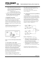
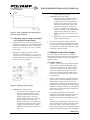
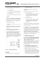
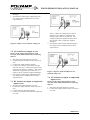
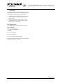
PM150/PM240 INSTALLATION MANUAL
PM150/PM240
Installation manual
Polyamp AB, Sweden
www.polyamp.com
10230-11.doc
Page 1 (9)
PM150/PM240 INSTALLATION MANUAL
Warranty
All Polyamp DC/DC converters are warranted against defective material and
workmanship. This warranty is valid for 24 months from the date of delivery.
We will repair or replace products which prove to be defective during the
warranty period. The warranty is valid only if the converter is used within
specification.
Manual
This manual is as complete and actual as possible at the time of printing.
However, the information may have been updated since then. Polyamp AB
reserves the right to make changes in this manual without notice.
The exclamation point within an equilateral triangle is intended to alert the user to presence of important
operating and maintenance instructions in the literature accompanying
The lightning flash with arrowhead, within an equilateral triangle, is intended to alert the user to presence of
uninsulated ”dangerous voltage” within the products enclosure that may be of sufficient magnitude to constitute
a risk of electric shock to persons
Caution!
To prevent the risk of electric shock, do not open enclosure. No serviceable parts inside. Refer servicing to
qualified service personnel only
Polyamp AB, Sweden
www.polyamp.com
10230-11.doc
Page 2 (9)
PM150/PM240 INSTALLATION MANUAL
CONTENTS
1 BEFORE INSTALLATION..............................................................................................................................4
2 INSTALLATION...............................................................................................................................................4
3 PARALLEL CONNECTION ...........................................................................................................................5
3.1 SERIES DIODE ON THE OUTPUT ........................................................................................................................5
3.2
CONNECTING CONVERTERS IN PARALLEL ON THE OUTPUT ........................................................................5
3.3
ADJUSTING OUTPUT VOLTAGE WHEN UNITS ARE PARALLELED ON THE OUTPUT ........................................6
4 MULTIPLE LOADS AT THE OUTPUT ........................................................................................................6
4.1 SHORT-CIRCUITS ............................................................................................................................................6
5 ALARM ..............................................................................................................................................................7
6 OUTPUT OVER VOLTAGE PROTECTION................................................................................................7
7 ISOLATION VOLTAGE TEST.......................................................................................................................7
7.1 DC ISOLATION TEST OUTPUT TO CASE ............................................................................................................7
7.2 AC ISOLATION TEST OUTPUT TO CASE ............................................................................................................8
7.3
DC ISOLATION TEST INPUT TO OUTPUT AND INPUT TO CASE ......................................................................8
7.4
AC ISOLATION TEST INPUT TO OUTPUT AND INPUT TO CASE ......................................................................8
8 OPTION H, INRUSH CURRENT LIMIT ......................................................................................................8
9 TROUBLE SHOOTING ...................................................................................................................................9
9.1 THERE IS NO OUTPUT VOLTAGE ......................................................................................................................9
9.2
THE INPUT FUSE BLOWS WHEN THE INPUT IS CONNECTED..........................................................................9
9.3
THE CONVERTER STARTS AND STOPS REPEATEDLY ...................................................................................9
9.4 FAULT REPORT ...............................................................................................................................................9
Polyamp AB, Sweden
www.polyamp.com
10230-11.doc
Page 3 (9)
PM150/PM240 INSTALLATION MANUAL
1 Before installation
On the front panel label the following is displayed:
Converter type name, input voltage range, nominal
output voltage, serial number, options, article
number, isolation voltages and ambient temperature
range. The converter type name consists of model
name PM150 or PM240 followed by input code
and output voltage. Two examples:
• ”Type: PM150B24” has input code ”B” and
nominal output voltage 24Vd.c.
• ”Type: PM240 110/48” has input code ”110”
and nominal output voltage 48Vd.c.
Input, output and case are galvanically separated
from each other. You can thus choose how you
want the system connected.
The input is protected against reverse polarity by a
parallel diode at the input on models with input
code A, B, 24 and 48. This diode, however, is only
intended to blow an external input fuse. C, D, 110
and 220 input codes have a series diode.
The input shall be fused with an approved fuse with
a slow blow characteristic and high breaking
capacity. See Table 1.
PM150 input fuses
Input voltage code
Time delay fuse
A
20 A
B
10 A
C
4A
D
2.5 A
PM240 input fuses
Input voltage code
Time delay fuse
24
15 A
48
8A
110
4A
220
2A
Table 1. Recommended input fuses.
There are two reasons we do not include the fuse.
1. DC-networks should be fused at the distribution
point to protect the cable.
2. Different applications require different types of
fuses.
If the converter is mounted in an electric vehicle, an
external series diode on the input is recommended.
Please contact your Polyamp dealer.
If the converter supplies a DC-motor, we
recommend an external parallel diode at the motor
poles to protect against reverse voltages.
Polyamp AB, Sweden
For the disconnection ability, an external
disconnection device, which is able to disconnect
both polarities, shall be incorporated with the input
power supply cord. The disconnection device must
be properly labelled and easy accessible.
2 Installation
The converter shall be mounted in an enclosure,
which meets the demands of EN60950 regarding
fire, voltage hazard and mechanical strength.
The converter is supplied with mounting plates.
With these you can mount the converter in any
direction. The converter is convection cooled and
in order to get sufficient cooling there shall be a
minimum of 30 to 50 mm space at upper and lower
parts of the converter. If this is not possible, we
recommend the use of an external fan.
Note that the expected life of the converter is
dependant on converter temperature. For every
10°C that the temperature is lowered the expected
life is approximately doubled. It is therefore crucial
to cater for good ventilation and if possible to
reduce ambient temperature.
To meet the EMC specifications in the enclosed
”declaration of conformity” use twisted-pairs for
connecting input, output and alarm. Shielded cables
are not necessary.
1. Connect protective earth to the connection
marked no 40. Use a ring terminal that has been
crimped by an appropriate tool.
2. Connect the output. The converter output is
short-circuit proof by a constant current limit
which works unlimited in time. Therefore there
is no need to fuse the load (unless you use
multiple loads, see below). The current limit is
fixed to 105% of nominal output current.
• If the converter is to be connected in parallel
at the output, please consult 3 Parallel
connection on page 5.
• If you use multiple loads, please consult 4
Multiple loads at the output on page 6.
• If you intend to use the alarm, please consult
5 Alarm on page 7.
3. Connect the input cables. Bundle input cables
together at the terminals separated from the
output cables. Make the same arrangement on
the output side. This is to make sure one cable
will not bridge the insulation barrier in case of
coming lose.
4. Start the converter with your external input
disconnection device.
Beware of hazardous voltages!
• The output voltage can be adjusted +10% to
-5% of nominal output voltage with the
www.polyamp.com
10230-11.doc
Page 4 (9)
PM150/PM240 INSTALLATION MANUAL
potentiometer marked V.ADJ on the front
panel. Clockwise turn increases the output
voltage. The potentiometer has 15 turns. If
you have connected units in parallel on the
output, the procedure of adjusting the output
voltage is described in 3.3
Adjusting output voltage when
units are paralleled on the output on page 6.
4. When the converter is disconnected, switch-off
the input voltage with the disconnecting unit.
Disconnect the input cables first, then output
and last the protective case connection.
3 Parallel connection
If a redundant power supply system is requested,
two or more converters can be connected in
parallel. To achieve redundancy the number of
converters must be dimensioned to carry the whole
load even if one converter is faulty. Connect your
load to the + output after the series diode (cathode),
see Figure 1.
system. Otherwise there will be no alarm indication
from a faulty converter unless all units are in
current limit and the output voltage drops 10%
below nominal output voltage.
Do not forget to fuse the inputs separately to
achieve redundancy.
3.2 Connecting converters in parallel on
the output
The expected life of the converter is dependant on
converter temperature. It is therefore important for
paralleled unit to share the load as equal as possible
to reduce the converter temperature. To achieve
good current sharing the converters must have
separate cables to the load. The cables should be
dimensioned to have a voltage drop, Ud, between
the converter and the load at maximum current
capacity, see Figure 2 and Figure 3.
Another reason for connecting two or more
converters in parallel is to get more power. Use the
output with series diode, see Figure 1.
Figure 2. Voltage drop Ud = Uout - Uload
Figure 1. The series diod output marked with an
arrow
3.1 Series diode on the output
The series diode protects the converter output from
external voltage sources. A series diode is
necessary if the output is connected in parallel with
another power supply or if you require redundant
operation. If a converter breaks down with an
internal short-circuit on the output and other
converters are connected in parallel on the output,
the broken unit will short-circuit the others if the
series diode is not used. This might cause excessive
heat or even fire in the faulty unit.
• When the series diode is used, which we
recommend, the voltage drop should be
approximately 1.0% of nominal output voltage
(to also compensate for the negative
temperature coefficient of the diode).
• When the series diode is not used, this is not
recommended, the voltage drop should be
approximately 0.5% of nominal output voltage.
Note that the voltage drop affects the load
regulation (the voltage at the load), see Figure 3.
If the series diode is used, the alarm relay will
switch to ”ALARM” on the faulty unit if one
converter breaks down in a redundant power supply
Polyamp AB, Sweden
www.polyamp.com
10230-11.doc
Page 5 (9)
PM150/PM240 INSTALLATION MANUAL
Figure 3. Load regulation with voltage drop Ud
between output and load
3.3 Adjusting output voltage when units
are paralleled on the output
1. Connect and start all converters according to 2
Installation on page 4. We recommend using the
series diode and separate cables as mentioned
above in 3.2 Connecting converters in parallel
on the output.
2. Measure the voltage at the load. Connect
voltmeters as showed in Figure 4. If you have
only access to one voltmeter you must move it
around to make the adjustments. This will take
time but is of course possible.
ii. Repeat from i. until you reach the desired
output voltage at the load.
4. To decrease the output voltage.
i. Decrease the output voltage by turning
the potentiometer marked ”V.ADJ”
counter clockwise on the unit with the
highest output voltage until you reach
the desired voltage at the load or until
the output voltage does not decrease
anymore (as the other units supply all
current). To find the unit with the highest
output voltage, measure the voltage
difference before the series diode, as in
Figure 4.
ii. Repeat from i. until you reach the desired
output voltage at the load.
5. To achieve good current sharing, adjust all
converters so that the voltage difference before
the series diode is 0.00V between all units that
are connected in parallel and so that the voltage
at the load is still the desired.
4 Multiple loads at the output
If you are using several loads, we recommend
fusing them separately with fast acting fuses. Some
considerations regarding short-circuits should be
taken. See below.
4.1 Short-circuits
1. If there is a short-circuit in one branch and the
total current in all branches does not exceed
105% of the nominal current of the converter
(see label on front panel), the output voltage
will not be affected. The time for the fuse to
blow can be calculated from the data sheet of
the fuse if you know the short-circuit current
trough the fuse.
Figure 4. Adjusting output voltage
3. To increase the output voltage.
i. Increase the output voltage by turning
the potentiometer marked ”V.ADJ”
clockwise on the unit with the lowest
output voltage until you reach the
desired voltage at the load or until the
output voltage does not increase
anymore (as the unit is in current limit).
To find the unit with the lowest output
voltage you can measure the voltage
difference before the series diode, as in
Figure 4.
Polyamp AB, Sweden
2. If there is a short-circuit in one branch and the
total current in all branches does exceed 105%
of the nominal current of the converter, the
output voltage will drop until the fuse is blown.
Depending on the impedance of the short-circuit
(whether it is abrupt or merely an overload) and
the resistance of the load cables, the effects of a
short-circuit will vary.
Long cables reduce short-circuit currents,
resulting in longer delay until the fuse is blown
and hence an increased voltage dip. Light
overload does not necessarily result in a blown
fuse.
To reduce the voltage drop at short-circuit and
if any branch has more than approximately 30%
of the total output current of the converter, a
large external capacitor is recommended. Such a
capacitor will supply the peak current needed to
www.polyamp.com
10230-11.doc
Page 6 (9)
PM150/PM240 INSTALLATION MANUAL
blow the fuse, see Figure 5. To calculate the
capacitor needed, use the following formula:
C = 1.2 x ( IS x Δt ) / ΔU
• The output voltage is not within +15% /-10% of
nominal output voltage.
1.2 = Safety margin.
Otherwise the relay contact is in the position
”NORMAL”.
IS = Short-circuit current through the fuse.
The alarm relay can be connected in two ways:
Δt = Time before the fuse blows (see data
sheet on the fuse).
1. Normally Open (NO).
ΔU = Acceptable voltage dip before the fuse
blows.
Example:
You have a 1A fuse with fast characteristic and
the short-circuit current is 10A. The data sheet
gives you that Δt = 10ms. The output voltage is
24V, and you can accept 10% voltage drop =>
ΔU=24 x 0.1= 2.4V.
The capacitance you need:
i. Connect twisted-pair (0.25mm2 -1.5mm2)
from centre pin of the removable alarm
connector and connector pin marked
”ALARM”.
2. Normally Closed (NC).
i. Connect twisted-pair (0.25mm2 -1.5mm2)
from centre pin of the removable alarm
connector and connector pin marked
”NORMAL”.
C = 1.2 x ( IS x Δt ) / ΔU = 1.2 x 10 x 0.01 / 2.4
= 50,000µF
The relay is isolated 2500Va.c. from input, output
and case. The relay can switch maximum 30V/5A
(a.c. and d.c. values).
Choose a capacitance with a rated voltage of at
least 115% of nominal output voltage of the
converter.
6 Output over voltage protection
Repeat this calculation for all branches and
choose the highest capacitance value.
3. It is sometimes difficult to estimate the shortcircuit current when the nature of a fault is
unknown. In this case a voltage dip might
appear under some short-circuit conditions even
with a large capacitor present. If a voltage dip is
critical in one branch it is recommended to use a
separate DC/DC converter supplying this
branch.
All models are equipped with an internal output
over voltage protection circuit (OVP). It consists of
an additional voltage regulator operating in parallel
with the main regulator. The output voltage is
limited to approximately 15% above the nominal
output voltage. As long as the OVP circuit is active
the alarm relay is set to ”ALARM” state.
7 Isolation voltage test
Each converter has been isolation tested in factory
before delivery. Warning! An isolation test shall
only be performed by personnel aware of the
dangers and hazards of the test.
The isolation voltage is 2500Va.c. on all models. If
your isolation test equipment cannot supply this
current, you can perform a DC isolation test with
4000Vd.c (2500V x √2 x 1.1 ≈ 4000Vd.c where
1.1 = safety factor).
7.1 DC isolation test output to case
Figure 5. Connecting multiple loads.
5 Alarm
The alarm relay switches to ”ALARM” state if:
Polyamp AB, Sweden
1. Disconnect all cables from the converter.
2. Connect the input terminals of the converter to
case.
3. Connect the output terminals together.
4. Connect your isolation tester between output
and case. See Figure 6. Raise the voltage of the
isolation tester from 0 to 4000Vd.c. Check that
the leakage current does not exceed 5µA. The
voltage should not be applied for more than a
www.polyamp.com
10230-11.doc
Page 7 (9)
PM150/PM240 INSTALLATION MANUAL
few seconds or the Y-capacitors might be
damaged.
5. Turn off the isolation tester and discharge the
test voltage with a 10 MΩ resistor between
output and case.
Figure 6. Output to case isolation voltage test.
Figure 7. Raise the voltage of the isolation
tester from 0 to 4000Vd.c. Check that the
leakage current does not exceed 5µA. The
voltage should not be applied for more than a
few seconds or the Y-capacitors might be
damaged.
5. Turn off the isolation tester and discharge the
test voltage with a 10 MΩ resistor between
input and case.
7.2 AC isolation test output to case
Beware of the rather high capacitive earth
currents (about 100mA) that will occur during
this test.
1. Disconnect all cables from the converter.
2. Connect the input terminals of the converter to
case.
3. Connect the output terminals together.
4. Connect your isolation tester between output
and case. See Figure 6. Raise the voltage of the
isolation tester from 0 to 2500Va.c. The voltage
should not be applied for more than one (1)
minute or the Y-capacitors might be damaged.
5. Turn off the isolation tester and discharge the
test voltage with a 10 MΩ resistor between
output and case.
7.3 DC isolation test input to output and
input to case
1. Disconnect all cables from the converter.
2. Connect the output terminals of the converter to
case.
3. Connect the input terminals together.
4. Connect your isolation tester between input and
case. See
Polyamp AB, Sweden
Figure 7. Input to output and input to case
isolation voltage test.
7.4 AC isolation test input to output and
input to case
Beware of the rather high capacitive earth
currents (about 100mA) that will occur during
this test.
1. Disconnect all cables from the converter.
2. Connect the output terminals of the converter to
case. See
www.polyamp.com
10230-11.doc
Page 8 (9)
PM150/PM240 INSTALLATION MANUAL
PM150 (normal input voltage range)
Input voltage code
Input voltage range
B
20-60Vd.c.
C
50-150Vd.c.
D
90-270Vd.c.
PM150 with option H
Input voltage code
Input voltage range
B
30-60Vd.c.
C
75-150Vd.c.
D
115-270Vd.c.
Figure 7.
3. Connect the input terminals together.
4. Connect your isolation tester between input and
case. See
Table 2. Input voltage range with and without
option H
The unit starts if the voltage is within the normal
input voltage range, but depending on the load (if
the NTC is heated up) a load change might cause
the converter to stop and start as described before.
All models have a ”slow start” feature. To reduce
input current during start up the output capacitors
are charged ”slowly” (approximately 0.1s).
9 Trouble shooting
Figure 7. Raise the voltage of the isolation
tester from 0 to 2500Va.c. The voltage should
not be applied for more than one (1) minute or
the Y-capacitors might be damaged.
5. Turn off the isolation tester and discharge the
test voltage with a 10 MΩ resistor between
input and case.
8 Option H, inrush current limit
Converters marked with ”Options: H” on the front
label are equipped with ”inrush current limit”
feature. The input capacitors are charged through
an NTC resistor to reduce the input current during
start up. This feature is only available on the
PM150 models with input codes B, C and D.
The input voltage range is changed when this
option is included, see Table 2. This is because if
the load changes from 0 to 100% abruptly, the
input current also changes abruptly. This will cause
a voltage drop across the NTC resistor (until it
heats up). If the input voltage is only slightly higher
than the start voltage of the converter this voltage
drop will cause the converter to stop. The converter
will then start and stop several times until the NTC
resistor is heated up. We have therefore increased
the lowest input voltage on units with a NTC
resistor so this behaviour not arises.
Polyamp AB, Sweden
9.1 There is no output voltage
1. Check that the input fuse is not broken.
2. Check that the input voltage polarity is correct.
3. Check that the input voltage is within the
specified limits, see front label.
4. The converter may be in current limit due to
excessive output current or an external shortcircuit on the output.
• Disconnect the input.
• Disconnect the load.
• Connect the input again and measure the
output voltage.
If the converter now starts the load was too
heavy or there was a short-circuit.
• If there is an external short-circuit, remove
it.
• If the load is too large decrease the load or
consult your Polyamp dealer.
5. The unit is broken. Contact your Polyamp
dealer.
9.2 The input fuse blows when the input
is connected
1. Check that the input voltage polarity is correct.
2. Check that the input fuse is of time delay type
and with correct current rating. See Table 1.
3. The unit is broken. Contact your Polyamp
dealer.
www.polyamp.com
10230-11.doc
Page 9 (9)
PM150/PM240 INSTALLATION MANUAL
9.3 The converter starts and stops
repeatedly
All models have an over/under voltage protection
which shuts down the converter if the input voltage
is not within specified limits (see front label).
1. The cables to the converter input may be undersized, causing too high voltage drop in the
supply cables.
2. Your supply does not have enough current
capacity so the input voltage to the converter
drops below specified limit.
9.4 Fault report
We suggest that you return a faulty converter to:
POLYAMP AB
Box 229 / Bäckgatan 10
S-597 25 ÅTVIDABERG
SWEDEN
Tel: +46 120 85400
Fax: +46 120 85405
or to your local Polyamp distributor.
To help us locate the fault, please describe the fault
and how and when it occurred.
Polyamp AB, Sweden
www.polyamp.com
10230-11.doc
Page 10 (9)