1
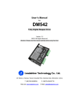
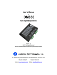
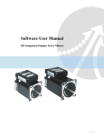
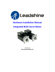
Hardware Installation Manual
IES Series Integrated Easy Servos
Part Number
IES
Frame Size
17: 42mm
23 :57mm
24: 60mm
www.leadshine.com
HWMN-IES-R20121030
Branch Series
Torque
Blank: Standard
09: 0.9Nm
A: Branch Series A 20: 2.0Nm
B: Branch Series B 40: 4.0Nm
…
…
Communication
Blank: Standard
485: RS485
CAN: CANOpen
…
Custom-built
Blank: Standard
...
ii
Leadshine reserves the right to make changes without further notice to
any products herein to improve reliability, function or design. Leadshine
does not assume any liability arising out of the application or use of any
product or circuit described herein; neither does it convey any license
under its patent rights of others.
Leadshine’s general policy does not recommend the use of its products
in life support or aircraft applications wherein a failure or malfunction
of the product may directly threaten life or injury. According to
Leadshine’s terms and conditions of sales, the user of Leadshine’s
products in life support or aircraft applications assumes all risks of such
use and indemnifies Leadshine against all damages.
©2012 by Leadshine Technology, All Rights Reserved
Change Log
HWMN-IES-R20121030
Revision Date
Changes
Version
2012-4-11
Original Create
HWMN-ISS57-R20120411
2012-10-30
Change part number
HWMN-IES-R20121030
iii
Safety Items
!
Notice
!
Read this manual carefully before trying to install the stepper drive into your system. The person
setup the stepper drive should have a better understanding on electronics and mechanics. Contact
Leadshine technical guys when have questions on this document.
Make sure the power supply voltage dose not exceed the drive’s input range. Double check the
connections and make sure the power lead polarity is correct.
Caution
!
Do not set high current to small stepper motor. It is possible that the motor will be damaged.
Warning
!
Disconnect the motor from the load if you are not sure the move direction. Adjust the axis in the
middle before trying to run the motor.
Caution
!
Never disconnect the motor lead when the power source is energized.
Warning
HWMN-IES-R20121030
iv
Table of Contents
1. Family Overview ......................................................................................................................................................... 1
Introduction ............................................................................................................................................................. 1
Applications ............................................................................................................................................................ 1
Product Covered ...................................................................................................................................................... 2
Mechanical Specifications ....................................................................................................................................... 2
Elimination of Heat ................................................................................................................................................. 2
2. Connectors and Pin Assignment .................................................................................................................................. 3
3. Control Signal Requirement ........................................................................................................................................ 5
Control Mode and Sequence Chart.......................................................................................................................... 5
4. Connecting Control Signal .......................................................................................................................................... 6
NPN Signal Connections ......................................................................................................................................... 6
PNP Signal Connections.......................................................................................................................................... 6
Differential Signal Connections .............................................................................................................................. 6
Output Signal Connections ...................................................................................................................................... 7
5. Power Supply Selection............................................................................................................................................... 7
Regulated or Unregulated Power Supply ................................................................................................................ 7
Multiple Drives ....................................................................................................................................................... 7
Selecting Supply Voltage......................................................................................................................................... 8
Recommended Supply Voltage................................................................................................................................ 8
6. Typical Connections .................................................................................................................................................... 9
7. RS232 Communication Connections .......................................................................................................................... 9
8. Configuring the Drive ............................................................................................................................................... 10
Introduction ........................................................................................................................................................... 10
Micro step Resolution Selection.............................................................................................................................11
Current Control Detail ............................................................................................................................................11
Fine Tuning ............................................................................................................................................................11
9. Protection Functions .................................................................................................................................................. 12
Over-current Protection ......................................................................................................................................... 12
Over-voltage Protection ........................................................................................................................................ 12
Position Error Protection ....................................................................................................................................... 12
Protection Indications ............................................................................................................................................ 12
10. Frequently Asked Questions .................................................................................................................................... 13
Problem Symptoms and Possible Causes .............................................................................................................. 13
Warranty ........................................................................................................................................................................ 14
Exclusions ............................................................................................................................................................. 14
Obtaining Warranty Service .................................................................................................................................. 14
Warranty Limitations............................................................................................................................................. 14
Shipping Failed Product ........................................................................................................................................ 14
Contact Us ..................................................................................................................................................................... 15
HWMN-IES-R20121030
Hardware Installation Manual of the IES Series
1. Family Overview
Introduction
Leadshine’s IES integrated easy servo motor is a stepper motor integrated with a 1,000-line (4,000 PPR) encoder and
a hybrid servo drive. At very compact size and with all components integrated, the IES can save mounting space,
eliminate encoder connection & motor wiring time, reduce interference, and cut/reduce cable and labor costs.
By adopting Leadshine’s latest hybrid servo control technology, the hybrid servo drive of the IES can drive the
stepper motor with high staring torque, high precision, smooth movement, and extra low noise at low speed
movement with no obvious resonance area. Different from constant-output-current output from a drive to a stepper
motor in normal open-loop stepper controls, output current of the IES is dynamic and changes depending on load
condition, same as servo controls. Therefore, it can significantly reduce motor heating and increase motor lifetime.
The drive takes step & direction input commands, and is capable of outputting in-position and fault signals back to a
motion controller or external devices, for complete system controls.
The integrated 1,000-line encoder of can offer the real-time motor shaft position to the drive. Based on that position,
the drive can then close the loop between the motor and drive, ensure no step is lost, and eliminate the possibility of
stall or loss of movement synchronization which is often found in open-loop stepper systems. By getting rid of
torque reservation in open-loop stepper systems, the IES can significantly improve high speed performance by as
much as 30%. In addition, the IES performs much better in response time and speed acceleration over open-loop step
systems.
Compared with brushless servo systems, the IES has much higher low speed torque, no overshooting & zero settling
time, no overshooting, no hunting, and no/little tuning. Significant cost cutting also makes the IES ideal for the
motion control systems in many applications.
Applications
Leadshine’s IES integrated easy servo motor offers an alternative solution to fill the gap between budget open-loop
stepper systems, and expensive high performance brushless servo systems. It combines the features of high
low-speed torque of open loop stepper, and closed-loop movements of traditional servo systems. Integration design
with motor, drive, and encoder significantly reduces setup time and cut costs of your control systems.
Advanced features over open-loop stepper systems, such as much higher high-speed torque, no loss of movement
synchronization, much lower motor heating, no obvious resonance area, etc., make the IES ideal product for
upgrading stepper systems to get performance boost for many stepper applications such as CNC routers, CNC laser
cutting machines, CNC milling machines, CNC lathes, medical / biotech equipments, lab automation instruments,
etc.
Features over traditional brushless servo systems, such as significant lower costs, no hunting, no overshooting, easy
setup, etc., make the IES ideal products in many traditional servo applications such as short distance movement
boding type machines and vision applications. Its natural feature of high low-speed torque makes the IES a perfect
product for replacing many high-cost servo applications with gear head speed reduction.
HWMN-IES-R20121030
1
Hardware Installation Manual of the IES Series
Product Covered
This manual covers the Leadshine integrated easy servo products as shown in the following table:
Output
Pulse
Frequency
Motor
Holding
Torque
Pulse/Direction
CW/CCW(Optional)
In-position
Alarm
200K(Default)
500K(Optional)
0.9Nm
Pulse/Direction
CW/CCW(Optional)
In-position
Alarm
200K(Default)
500K(Optional)
2.0Nm
Holding
Motor
Length of
Torque
Length ( L)
Motor + Drive
IES-2309
0.9Nm
56mm
87.65mm
800g
IES-2320
2.0Nm
80mm
111.65mm
1280 g
Part
Number
Input
Voltage
Pulse
Voltage
Control
Mode
IES-2309
DC
(20-50)V
DC
(0-24)V
IES-2320
DC
(20-50)V
DC
(0-24)V
Mechanical Specifications
Part Number
Weight
Elimination of Heat
·
Drive board’s reliable working temperature(case) should be <70℃(158 ℉ ), and motor working
temperature(surface) should be <80℃(176℉);
·
It is recommended to set 40% holding current percentage and use automatic idle-current mode, namely current
automatically reduce to 40% when motor stops, so as to reduce driver heating and motor heating;
·
Refer to the software operating manual for how to set holding current.
HWMN-IES-R20121030
2
Hardware Installation Manual of the IES Series
·
It is recommended to mount the integrated in a space allowing air flow for good heat conduction. Use forced
cooling method to cool the system if necessary.
2. Connectors and Pin Assignment
The IES23 has three connectors, a connector for control signals connections, a connector for RS232 communication
connections and a connector for power connections.
Control Signal Connector
Power Input Connector
RS232 Communication Connector
The control signal inputs include PULSE, DIRECTION and ENABLE and the control signal outputs include PED
(In-position) and ALARM. All the above control signals are integrated into one connector.
Control Signal Connector
Pin
Name
I/O
1
PUL+
I
2
PUL-
I
3
DIR+
I
4
DIR-
I
Description
Pulse Signal: In single pulse (pulse/direction) mode, this input represents pulse signal, active
each rising or falling edge (Set by DIP switch S6); In double pulse mode (software
configurable), this input represents clockwise (CW) pulse, active both at high level and low
level. 4.5-24V when PUL-HIGH, 0-0.5V when PUL-LOW. For reliable response, pulse width
should be longer than 2.5μs for 200K MAX input frequency or 1μs for 500K MAX input
frequency.
Direction Signal: In single-pulse mode, this signal has low/high voltage levels, representing
two directions of motor rotation. In double-pulse mode (software configurable), this signal is
counter-clock (CCW) pulse, active both at high level and low level. For reliable motion
response, DIR signal should be ahead of PUL signal by 5μs at least. 4.5-24V when DIR-HIGH,
0-0.5V when DIR-LOW. The motor direction can also be changed by DIP switch S5. Please
note that rotation direction is also related to motor-driver wiring match. Exchanging the
connection of two wires for a coil to the driver will reverse motion direction.
HWMN-IES-R20121030
3
Hardware Installation Manual of the IES Series
Control Signal Connector(Continued)
Pin
Name
I/O
5
ENA+
I
6
ENA-
I
7
PED+
O
8
PED-
O
9
ALM+
O
10
ALM-
O
Description
Enable signal: This signal is used for enabling/disabling the driver. In default, high level (NPN
control signal) for enabling the driver and low level for disabling the driver. Usually left
UNCONNECTED (ENABLED). Please note that the PNP and Differential control signals are
on the contrary, namely Low level for enabling. The active level of ENA signal is software
configurable.
In-position Signal: OC output signal, activated when actual motor position reaches to the
target. This port can sink or source MAX 20mA current at 24V. In default, the impedance
between PED+ and PED- is high impedance in normal operation and becomes low when the
target is reached. The active impedance of in-position signal can be software configurable
(see software manual).
Alarm Signal: OC output signal, activated when one of the following protection is activated:
over-voltage, over current and position following error. This port can sink or source MAX
20mA current at 24V. In default, the impedance between ALM+ and ALM- is low impedance
in normal operation and becomes high when any protection is activated. The active
impedance of alarm signal is software configurable.
The power input connector is a two pin screw terminal. It has the +Vdc and GND inputs which corresponding to the
positive and negative output the power supply, respectively.
Power Connector
Pin
Name
I/O
Description
1
+Vdc
I
Power Supply Input (Positive), 20-45VDC recommended, leaving rooms for voltage
fluctuation and back-EMF during deceleration.
2
GND
GND Power Ground (Negative)
The RS232 communication connector is used to configure the programmable parameters like micro step, holding
current percentage, active edge/level of control signal, etc. A PC with at least one serial port is required. You can
copy the software either from http://www.leadshine.com or form Leadshine CD. See the detail in software manual.
RS232 Communication Connector
Pin Name
+5V
1
I/O
O
O
Description
+5V power output ( Note: Do not connect it to PC’s serial port)
2
TxD
RS232 transmit.
3
GND
4
RxD
I
RS232 receive.
5
NC
-
Not connected.
GND Ground.
HWMN-IES-R20121030
4
Hardware Installation Manual of the IES Series
3. Control Signal Requirement
Control Mode and Sequence Chart
By default the IES integrated motor supports Pulse/Direction control mode. If CW/CCW control mode is needed,
you can use the PC software to change it. See more information in the software manual. In order to avoid problems
such as motor not moving, losing steps and only running at low speed, the PULSE, DIRECTION and ENABLE
signal must have the following sequence:
Symbol
tDS
tPHS / tPLS
tDD
tES
tED
Description
Direction Setup Time
Pulse High Level Setup Time
/ Pulse Low Level Setup Time
Direction DelayTime
Requirement
>2us
>2.5us, (For 200K MAX frequency)
>1.0us, (For 500K MAX frequency)
-
Enable Setup Time
>42.1ms
Enable Delay Time
>5us
HWMN-IES-R20121030
5
Hardware Installation Manual of the IES Series
4. Connecting Control Signal
The IES accepts both differential and single-ended inputs (including open-collector and PNP output). Choose
suitable connections type according to the controller type. Make sure the output port of the controller can sink or
source at least 10mA current for the input isolated opto-coupler. If the cable length is greater than 50cm, it is
recommended to use twisted shielded pair cable for these signal. Do not put the control signal cable together with the
cables which is used for high power or high current equipment, in case of electronic interference coupled into the
IES through air.
NPN Signal Connections
If the motion controller is not differential
output type, recommended to select
motion controller with NPN type output
as it can sink more current than source
current. In this connection, Pulse,
Direction and Enable signal share the
same VCC (Positive) terminal.
PNP Signal Connections
In this connection, Pulse, Direction and
Enable signal share the same ground
(negative) terminal.
Drive
Controller
PUL+
VCC
PULPUL
DIR+
DIR-
DIR
ENA+
ENA-
ENABLE
Controller
PUL
Drive
PUL+
VCC
DIR
PULDIR+
DIR-
ENABLE
ENA+
ENA-
Differential Signal Connections
For differential output controller, connect
to the integrated stepper accordingly.
HWMN-IES-R20121030
Controller
Drive
PUL+
PUL+
PUL-
PUL-
DIR+
DIR+
DIR-
DIR-
ENA+
ENA+
ENA-
ENA-
6
Hardware Installation Manual of the IES Series
Output Signal Connections
The IES integrated stepper offers the PED
(in-position) signal to indicate the
achievement of target position. The ALM
signal will be active when the integrated
stepper goes into error. The output of PED
and ALM is isolated and you can connect
them to the inputs of the controller as
shown in the right figure.
Controller
Drive
VCC
PED+
In-Position
PED-
ALM+
Alarm
ALMGND
5. Power Supply Selection
To achieve good driving performances, it is important to select supply voltage and output current properly. Generally
speaking, supply voltage determines the high speed performance of the motor, while output current determines the
output torque of the driven motor (particularly at lower speed). Higher supply voltage will allow higher motor speed
to be achieved, at the price of more noise and heating. If the motion speed requirement is low, it’s better to use lower
supply voltage to decrease noise, heating and improve reliability.
Regulated or Unregulated Power Supply
Both regulated and unregulated power supplies can be used to supply the drive. If regulated power supplies (such as
most switching supplies.) are indeed used, it is important to have large current output rating to avoid problems like
current clamp, for example using 4A supply for 3A motor-drive operation. On the other hand, if unregulated supply
is used, one may use a power supply of lower current rating than that of motor (typically 50%~70% of motor
current). The reason is that the drive draws current from the power supply capacitor of the unregulated supply only
during the ON duration of the PWM cycle, but not during the OFF duration. Therefore, the average current
withdrawn from power supply is considerably less than motor current. For example, two 3A motors can be well
supplied by one power supply of 4A rating.
Multiple Drives
It is recommended to have multiple drives to share one power supply to reduce cost, if the supply has enough
capacity. To avoid cross interference, DO NOT daisy-chain the power supply input pins of the drives. Instead, please
connect them to power supply separately.
HWMN-IES-R20121030
7
Hardware Installation Manual of the IES Series
Selecting Supply Voltage
Higher supply voltage can increase motor torque at higher speeds, thus helpful for avoiding losing steps. However,
higher voltage may cause bigger motor vibration at lower speed, and it may also cause over-voltage protection or
even drive damage. Therefore, it is suggested to choose only sufficiently high supply voltage for intended
applications, and it is suggested to use power supplies with theoretical output voltage of drive’s minimum + 10% to
drive’s maximum – 10%, leaving room for power fluctuation and back-EMF.
Driver Upper Input limit
Driver Upper Input limit –
10%
Maximum Safe Rating
Safe Region
Driver Lower Input limit +
Torque
Speed
10%
Heating
Vibration
Minimum Safe Rating
Driver Lower Input limit
Driver Input Voltage
Power Supply Voltage
Recommended Supply Voltage
Both Leadshine’s regulated and unregulated power supply has been designed specially for motion control.
Model
Voltage Range
Typical Voltage
Leadshine Power Supply
IES-2309
DC(20-50)V
DC 24V
RPS2410(RPS2410-L)
IES-2320
DC(20-50)V
DC 36V
RPS369
HWMN-IES-R20121030
8
Hardware Installation Manual of the IES Series
6. Typical Connections
Typical connections of IES-23xx for NPN control signal is as follows.
Controller
IES-23XX
VCC = 5 - 24V
PUL+
VCC
270O
PULPulse
DIR+
270O
DIRDirection
ENA+
270O
ENAEnable
ALM+
Alarm
ALMPED+
In-Positon
PED-
+Vdc
20 ~ 45VDC
GND
· In order to improve anti-interference performance of the drive, it is recommended to use twisted pair shield cable.
· To prevent noise incurred in PUL/DIR signal, pulse/direction signal wires and motor wires should not be tied up
together. It is better to separate them by at least 10 cm, otherwise the disturbing signals generated by motor will
easily disturb pulse direction signals, causing motor position error, system instability and other failures.
· If a power supply serves several drives, separately connecting the drives is recommended instead of
daisy-chaining.
· It is prohibited to pull and plug power connector while the drive is powered ON, because there is high current
flowing through motor coils (even when motor is at standstill). Pulling or plugging power connector with power on
will cause extremely high back-EMF voltage surge, which may damage the drive.
7. RS232 Communication Connections
The RS232 communication only use Transmit,
Receive and ground signals. Connect them to the
serial port accordingly. The right drawing shows
the RS232 communication cable with a 9-pin
D-Shell female connector.
5
NC
4
RXD
3
GND
2
TXD
1
NC
5
4
9
HWMN-IES-R20121030
3
8
2
7
iSS57-XX
Female DB9
RS232 Communication Pins
(Look from the front side)
1
6
9
Hardware Installation Manual of the IES Series
8. Configuring the Drive
Introduction
There is only one DIP switch to select the micro step resolution, change motor direction and active edge of pulse
edge. The motor current will be adjusted dynamically according to load condition.
Micro step resolution of the IES can be configured via a 4-bit DIP switch, or Leadshine’s tuning software ProTuner.
When all bits of the DIP switch are at “ON” positions, the integrated hybrid servo drive board will take the micro
step resolution setting set by the software (4000 by default). In this case, a user can re-configure the resolution to any
value between 200 and 102, 400 (increased by 1) through software. If any bit of the DIP switch is at “OFF” position,
the integrated drive board will take micro step revolution setting determined by bit positions of the DIP switch. Use
the following table for their resolution settings via the DIP switch.
Micro Step Resolution
Steps/Revolution
Software Configured
(Default 4000)
S5
S1
S2
S3
S4
On
On
On
On
800
Off
On
On
On
1600
On
Off
On
On
3200
Off
Off
On
On
6400
On
On
Off
On
12800
Off
On
Off
On
25600
On
Off
Off
On
51200
Off
Off
Off
On
1000
On
On
On
Off
2000
Off
On
On
Off
4000
On
Off
On
Off
5000
Off
Off
On
Off
8000
On
On
Off
Off
10000
Off
On
Off
Off
20000
On
Off
Off
Off
40000
Off
Off
Off
Off
Motor Rotation Direction
DIP switch S5 is used for changing motor shaft rotation direction. Changing
position from “ON” to “OFF”, or “OFF” to “ON” will reverse IES-2309
rotation direction.
Pulse Active Edge
S6
On
Off
Active rising edge of input pulse
Active falling edge of input pulse
HWMN-IES-R20121030
10
Hardware Installation Manual of the IES Series
Micro step Resolution Selection
The stepper motor moves one step when one pulse is applied to the stepper drive. If microstep is 1, the step angle is a
full step which is 1.8 degree for 2-phase stepper motor and 1.2 degree for 3-hpase stepper motor. Microstep can be
taken as the divisions of one full step. For example, stepper motor moves half of the full step when the microstep is 2.
For 2-phase stepper motor and drive, we have the following formula to calculate the microstep resolution, or pulse
counts of one motor shaft revolution:
Microstep
Re solution
=
200
´
Microstep
The motor speed can be calculated as follows:
Motor
Speed ( RPS )
=
Pulse
Input
Microstep
Frequency
Re solution
When selecting the drive’s micro step resolution for the system:
· Consider the MAX speed needed, MAX input frequency of driver and MAX output frequency of the controller.
· Micro step resolution of 1600 pulses/revolution (8 micro step) is suitable for most application.
· Micro step resolution of greater than 1600 only increases smoothness but not resolution.
Current Control Detail
Leadshine’s IES integrated step servo motor is integrated with a high-resolution 1,000-line optical incremental
encoder. That encoder can send the real-time shaft position back to the integrated drive of the IES. Like traditional
servo controls, the drive can automatically adjust the output current to the motor. The output current ranges between
the holding current and the close-loop current. When there is no pulse sent to the drive, the IES goes into idle mode
and the actual motor current is determined by the holding current percentage (similar to “idle current” of open loop
stepper drives). In normal working mode, the IES monitors the actual shaft position all the time. The current
outputted to the motor changes dynamically based on the tracking error between the actual position and the
commanded position.
Low holding current can reduce motor heating however also reduces the holding torque which is used to lock the
motor shaft at standstill. It is recommended to determine the holding current by whether or not there is big vibration
at start-up and how much lock torque is required, based on your actual applications.
Fine Tuning
Leadshine already loads default current-loop parameters and position-loop parameters. Those default parameter
values have been optimized. They should be good enough for most industrial applications, and there is no need to
tune them. However, if you want to fine tune the IES for best performance for your applications, Leadshine also
offers tuning software, ProTuner, which allows you to adjust those current-loop and position-loop parameters (see
software manual).
HWMN-IES-R20121030
11
Hardware Installation Manual of the IES Series
9. Protection Functions
To improve reliability, the IES incorporates some built-in protection functions. The Integrated stepper uses one red
LED to indicate the protection type. The periodic time of red is 4 s (seconds), and the blinking times of red LED
indicates what protection has been activated. Because only one protection can be displayed by red LED, so the drive
will decide what error to display according to their priorities. See the following Protection Indications table for
displaying priorities.
Over-current Protection
Over-current protection will be activated when continuous current exceeds 18A or in case of short circuit between
motor coils or between motor coil and ground, and RED LED will blink once within each periodic time.
Over-voltage Protection
When power supply voltage exceeds 60VDC, protection will be activated and red LED will blink twice within each
periodic time.
When above protections are active, the motor shaft will be free or the LED will blink. Reset
the drive by repowering it to make it function properly after removing above problems. Since
there is no protection against power leads (﹢,﹣) reversal, it is critical to make sure that power
supply leads correctly connected to drive. Otherwise, the drive will be damaged instantly.
!
Caution
Position Error Protection
When the position error exceeds the limit (software configurable, see software manual), position, protection will be
activated and red LED will blink seven times within each periodic time.
Protection Indications
Priority
Time(s) of
Blink
1st
1
Over-current protection activated when peak
current is greater than 18A
2nd
2
Over-voltage protection activated when drive
working voltage is greater than 60VDC
7
Position following error activated when position
following error limit exceeded the pre-set value
(1000 pulses by default, or value set value by a
customer)
3rd
HWMN-IES-R20121030
Sequence wave of red LED
Description
12
Hardware Installation Manual of the IES Series
10. Frequently Asked Questions
In the event that your drive doesn’t operate properly, the first step is to identify whether the problem is electrical or
mechanical in nature. The next step is to isolate the system component that is causing the problem. As part of this
process you may have to disconnect the individual components that make up your system and verify that they
operate independently. It is important to document each step in the troubleshooting process. You may need this
documentation to refer back to at a later date, and these details will greatly assist our Technical Support staff in
determining the problem should you need assistance.
Many of the problems that affect motion control systems can be traced to electrical noise, controller software errors,
or mistake in wiring.
Problem Symptoms and Possible Causes
Symptoms
Possible Problems
No power
Motor is not rotating
Microstep resolution setting is wrong
Fault condition exists
The drive is disabled
Motor rotates in the
The Direction signal level is reverse
wrong direction
Power supply voltage beyond drive’s input range
The drive in fault
Something wrong with motor coil
Wrong connection
Control signal is too weak
Control signal is interfered
Erratic motor motion
Something wrong with motor coil
Motor is undersized for the application
Acceleration is set too high
Power supply voltage too low
Excessive motor and Inadequate heat sinking / cooling
drive heating
Load is too high
HWMN-IES-R20121030
13
Hardware Installation Manual of the IES Series
Warranty
Leadshine Technology Co., Ltd. warrants its products against defects in materials and workmanship for a period of
12 months from shipment out of factory. During the warranty period, Leadshine will either, at its option, repair or
replace products which proved to be defective.
Exclusions
The above warranty does not extend to any product damaged by reasons of improper or inadequate handlings by
customer, improper or inadequate customer wirings, unauthorized modification or misuse, or operation beyond the
electrical specifications of the product and/or operation beyond environmental specifications for the product.
Obtaining Warranty Service
To obtain warranty service, a returned material authorization number (RMA) must be obtained from customer
service at e-mail: before returning product for service. Customer shall prepay shipping charges for products
returned to Leadshine for warranty service, and Leadshine shall pay for return of products to customer.
Warranty Limitations
Leadshine makes no other warranty, either expressed or implied, with respect to the product. Leadshine specifically
disclaims the implied warranties of merchantability and fitness for a particular purpose. Some jurisdictions do not
allow limitations on how long and implied warranty lasts, so the above limitation or exclusion may not apply to you.
However, any implied warranty of merchantability or fitness is limited to the 12-month duration of this written
warranty.
Shipping Failed Product
If your product fail during the warranty period, e-mail customer service at to obtain a returned material authorization
number (RMA) before returning product for service. Please include a written description of the problem along with
contact name and address. Send failed product to distributor in your area or: Leadshine Technology Co., Ltd. 3/F,
Block 2, Nanyou Tianan Industrial Park, Nanshan Dist, Shenzhen, China. Also enclose information regarding the
circumstances prior to product failure.
HWMN-IES-R20121030
14
Hardware Installation Manual of the IES Series
Contact Us
China Headquarters
Address: 3/F, Block 2, Nanyou Tianan Industrial Park, Nanshan District Shenzhen, China
Web: http://www.leadshine.com
Sales Hot Line:
Tel: 86-755-2641-7674 (for Asia, Australia, Africa region)
86-755-2640-9254 (for Europe region)
86-755-2641-7617 (for America region)
Fax: 86-755-2640-2718
Email: [email protected].
Technical Support:
Tel: 86-755-2641-8447, 86-755-2641-8774, 86-755-2641-0546
Fax: 86-755-2640-2718
Email: [email protected](for All)
Leadshine U.S.A
Address: 25 Mauchly, Suite 318 Irvine, California 92618
Tel: 1-949-608-7270
Fax: 1-949-608-7298
Web: http://www.leadshineUSA.com
Email: [email protected] and [email protected].
HWMN-IES-R20121030
15