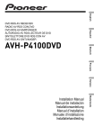
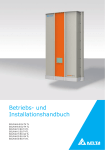
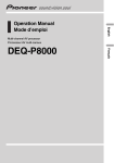
1
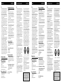
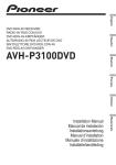
2
•
10
4
3
6
•
5
•
Fig. 3
Abb. 3
Afb. 3
Fig. 1
Abb. 1
Afb. 1
•
•
Installing the unit
7
Mounting with brackets (Fig. 1)
11
1.
2.
3.
4.
5.
6.
8
12
Fig. 2
Abb. 2
Afb. 2
Fig. 4
Abb. 4
Afb. 4
Tapping screw (4 × 12 mm)
Screw (4 × 8 mm)
Bracket
Do not close this area.
Drill 2 to 2.5 mm diameter holes.
Car mat or chassis
•
•
•
•
•
Try not to bend the optical cable sharply. If it is
necessary to bend it sharply, make sure that the
bending radius is at least 25 mm, otherwise the
cable will not transfer signals properly and so
this unit will not work properly.
Route the optical cable so that nothing heavy
rests on it, and so that it cannot be stepped on or
caught in anything – for instance, a door.
Make a loop of diameter at least 200 mm with
the remaining optical cable so that the cable does
not get strained.
When plugging the optical cable into the unit,
use the supplied cable clamps to prevent the
cable from being bent sharply.
Route the optical cable so that it does not get
caught in moving parts such as the gear shift,
hand brake, or seat sliding mechanism. Keep the
cable away from hot spots, such as near the
heater outlet.
•
•
•
•
•
Using the corrugated tube (Fig. 3)
To prevent the optical cable from being strained,
use the corrugated tube after cutting it to the correct length.
•
•
• Insert the optical cable into the corrugated tube.
9. Optical cable
10. Corrugated tube
•
Mounting the clamp (Fig. 4)
•
The clamp is used to secure the optical cable
when using it. The other clamp is installed on the
back side of the head unit similarly and used to
secure the optical cable.
1. Insert the clamp in the direction
indicated in the figure, and turn it 90
degrees to lock.
11. Clamp
Mounting with velcro tape (Fig. 2)
2. Secure the optical cable.
Thoroughly wipe off the surface before affixing
the velcro tape.
7. Velcro tape
8. Car mat or chassis
12. Optical cable
•
•
•
•
•
•
When an external power amp is being used with
this system, be sure not to connect the blue/white
lead to the amp’s power terminal. Likewise, do
not connect the blue/white lead to the power terminal of the auto-antenna. Such connection could
cause excessive current drain and malfunction.
To avoid short-circuiting, cover the disconnected
lead with insulating tape. Especially, insulate the
unused speaker leads without fail. There is a possibility of short-circuiting if the leads are not
insulated.
To prevent incorrect connection, the input side of
the IP-BUS or optical cable connector is blue,
and the output side is black. Connect the connectors of the same colors correctly.
If this unit is installed in a vehicle that does not
have an ACC (accessory) position on the ignition
switch, the red lead of the unit should be connected to a terminal coupled with ignition switch
ON/OFF operations. If this is not done, the vehicle battery may be drained when you are away
from the vehicle for several hours.
F
ACC
O
ACC position
•
•
•
F
O
STAR
<KSNNF> <04D00000>
•
Precaution:
This unit is for vehicles with a 12-volt battery
and negative grounding. Before installing it in a
recreational vehicle, truck, or bus, check the battery voltage.
To avoid shorts in the electrical system, be sure
to disconnect the · battery cable before beginning installation.
Refer to the owner’s manual for details on connecting the power amp and other units, then
make connections correctly.
Secure the wiring with cable clamps or adhesive
tape. To protect the wiring, wrap adhesive tape
around them where they lie against metal parts.
Route and secure all wiring so it cannot touch
any moving parts, such as the gear shift, handbrake and seat rails. Do not route wiring in
places that get hot, such as near the heater outlet.
If the insulation of the wiring melts or gets torn,
there is a danger of the wiring short-circuiting to
the vehicle body.
Don’t pass the yellow lead through a hole into
the engine compartment to connect to the battery.
This will damage the lead insulation and cause a
very dangerous short.
Do not shorten any leads. If you do, the protection circuit may fail to work when it should.
Never feed power to other equipment by cutting
the insulation of the power supply lead of the
unit and tapping into the lead. The current capacity of the lead will be exceeded, causing overheating.
When replacing fuse, be sure to use only fuse of
the rating prescribed on the fuse holder.
Since a unique BPTL circuit is employed, never
wire so the speaker leads are directly grounded or
the left and right · speaker leads are common.
Speakers connected to this unit must be highpower types with minimum rating of 50 W and
impedance of 4 to 8 ohms. Connecting speakers
with output and/or impedance values other than
those noted here may result in the speakers catching fire, emitting smoke or becoming damaged.
When this product’s source is switched ON, a
control signal is output through the blue/white
lead. Connect to an external power amp’s system
remote control or the car’s Auto-antenna relay
control terminal (max. 300 mA 12 V DC). If the
car features a glass antenna, connect to the antenna booster power supply terminal.
N
<CRD3876-A> EW
9
•
STAR
Printed in Japan
Imprimé au Japon
•
Note:
N
This product conforms to new cord colors.
Los colores de los cables de este producto se conforman con un nuevo código de colores.
Dieses Produkt entspricht den neuen Kabelfarben.
Le code de couleur des câbles utilisé pour ce produit
est nouveau.
Questo prodotto è conforme ai nuovi codici colori.
De kleuren van de snoeren van dit toestel zijn gewijzigd.
1
Routing the optical cable
OF
DEQ-P6600
MANUEL D’INSTALLATION
INSTALLATION MANUAL
•
Before finally installing the unit, connect the
wiring temporarily, making sure it is all connected up properly, and the unit and the system work
properly.
Use only the parts included with the unit to
ensure proper installation. The use of unauthorized parts can cause malfunctions.
Consult with your nearest dealer if installation
requires the drilling of holes or other modifications of the vehicle.
Install the unit where it does not get in the driver’s way and cannot injure the passenger if there
is a sudden stop, like an emergency stop.
When mounting this unit, make sure none of the
leads are trapped between this unit and the surrounding metalwork or fittings.
Do not mount this unit near the heater outlet,
where it would be affected by heat, or near the
doors, where rainwater might splash onto it.
Before drilling any mounting holes always check
behind where you want to drill the holes. Do not
drill into the gas line, brake line, electrical wiring
or other important parts.
If this unit is installed in the passenger compartment, anchor it securely so it does not break free
while the car is moving, and cause injury or an
accident.
If this unit is installed under a front seat, make
sure it does not obstruct seat movement. Route
all leads and cords carefully around the sliding
mechanism so they do not get caught or pinched
in the mechanism and cause a short circuit.
<ENGLISH>
OF
•
Connecting the Units
T
Note:
<ENGLISH>
T
Installation
No ACC position
The black lead is ground. Please ground this lead
separately from the ground of high-current products such as power amps.
If you ground the products together and the
ground becomes detached, there is a risk of damage to the products or fire.
To ensure proper heat dissipation of this product,
take special care not to block the cooling fan side
of this product.
Cords for this product and those for other products may be different colors even if they have
the same function. When connecting this product to another product, refer to the supplied
manuals of both products and connect cords that
have the same function.
•
•
•
•
•
•
•
•
Intente no doblar mucho el cable óptico. Si es
necesario doblar el cable, asegúrese de que el
radio de curvatura es de por lo menos 25 mm, de
lo contrario el cable no transferirá las señales
apropiadamente y, por lo tanto, la unidad no funcionará correctamente.
Encamine el cable óptico de modo que nada peso
quede sobre el cable, y de modo que no pueda
ser pisado o agarrado en algo - por ejemplo, una
puerta.
Haga un bucle con un diámetro de por lo menos
200 mm con el cable óptico restante de modo
que el cable no se deforme.
Al conectar el cable óptico a la unidad, utilice la
abrazadera de cable suministrada para prevenir
que el cable se doble excesivamente.
Encamine el cable óptico de modo que no se
agarre en las piezas móviles tales como el cambio de engranajes, freno de mano, o mecanismo
de deslice de los asientos. Mantenga el cables
alejado de puntos calientes, tales como cerca de
la salida del calentador.
•
Para prevenir que el cable óptico se deforme,
utilice el tubo ondulado después de cortarlo al
largo correcto.
•
Montaje con cinta adherente (Fig. 2)
2. Asegure el cable óptico.
Limpie completamente la superficie antes de fijar
la cinta adherente o Velcro.
7. Cinta adherente (Velcro)
8. Alfombra del automóvil o chasis
12. Cable óptico
•
•
•
•
•
O
Posición ACC
•
•
F
O
No en la posición ACC
El conductor negro es la masa. Conecte a masa
este conductor separadamente desde la masa de
los productos de alta corriente tal como los
amplificadores de potencia.
Si conecta juntos a masa los productos y la masa
se desconecta, se crea el riesgo de daños a los
productos o de incendios.
Para asegurar una disipación de calor apropiada
de este producto, tenga especial precaución de no
bloquear el lado del ventilador de enfriamiento
de este producto.
Los cables para este producto y aquéllas para
otros productos pueden ser de colores diferentes
aun si tienen la misma función. Cuando se
conecta este producto a otro, refiérase a los
manuales de ambos productos y conecte los
cables que tienen la misma función.
Einbau des Geräts
Montage mit Halterungen (Abb. 1)
Scheidschraube (4 × 12 mm)
Schraube (4 × 8 mm)
Halterung
Diesen Bereich nicht verdecken.
Löcher mit einem Durchmesser von 2 bis 2,5 mm
bohren.
6. Bodenmatte oder Fahrwerk
1.
2.
3.
4.
5.
Montage mit Klettband (Abb. 2)
Vor Anbringen des Klettbands die Haftfläche
gründlich säubern.
7. Klettband
8. Bodenmatte oder Fahrwerk
•
Zur besonderen Beachtung:
•
•
•
•
•
Biegen Sie das Lichtleiterkabel nicht scharf ab. Ein
minimaler Biegeradius von 25 mm muss
eingehalten werden, da Signale anderenfalls nicht
richtig über das Kabel übertragen werden können,
und das Gerät in einem derartigen Fall auch nicht
richtig funktioniert.
Bei der Verlegung des Lichtleiterkabels ist darauf zu
achten, dass es nicht unter schweren Gegenständen
zu liegen kommt, dass es nicht betreten werden und
es sich nicht irgendwo verfangen kann, z.B. an einer
Tür.
Bündeln Sie das überschüssige Lichtleiterkabel mit
einem Durchmesser von mindestens 200 mm,
sodass es nicht beansprucht wird.
Verwenden Sie zum Anschließen des
Lichtleiterkabels an das Gerät die mitgelieferte
Kabelklemmen, um ein scharfes Abbiegen des
Kabels zu vermeiden.
Verlegen Sie das Lichtleiterkabel unbedingt so, dass
es sich nicht an beweglichen Teilen verfangen kann,
wie z.B. dem Schalthebel, der Feststellbremse oder
der Sitzschiene. Halten Sie das Kabel von warmen
Stellen, wie z.B. von Warmluftdüsen, fern.
•
•
•
•
•
Gebrauch des Wellrohrs (Abb. 3)
Um eine Beanspruchung des Lichtleiterkabels zu
vermeiden, sollten Sie das Wellrohr verwenden,
nachdem Sie dieses auf die richtige Länge
zugeschnitten haben.
•
•
• Führen Sie das Lichtleiterkabel in
das Wellrohr ein.
9. Lichtleiterkabel
10. Wellrohr
Anbringen der Klemme (Abb. 4)
Die Klemme dient zum Sichern des
Lichtleiterkabels bei Gebrauch. Die andere
Klemme ist auf gleiche Weise an der Rückseite
des Hauptgeräts angebracht und wird zum
Sichern des Lichtleiterkabels verwendet.
1. Die Klemme in der in der Abbildung
gezeigten Ausrichtung einsetzen und
zur Verriegelung um 90 Grad
drehen.
11. Klemme
2. Das Lichtleiterkabel sichern.
12. Lichtleiterkabel
•
•
•
Dieses Gerät ist für Fahrzeuge mit 12-V-Batterie
und negativer Erdung (Minuspol an Masse)
ausgelegt. Prüfen Sie vor dem Einbau in ein
Wohnmobil, einen Lastwagen oder Bus die
Batteriespannung.
Um Kurzschlüsse im elektrischen System zu
verhindern, ist unbedingt vor dem Einbau das
Minus-Batteriekabel ≠ abzutrennen.
Nehmen Sie die Anschlüsse gemäß den
Anweisungen zum Anschluss des
Leistungsverstärkers und anderer Geräte in der
Bedienungsanleitung vor.
Sichern Sie die Leitungen mit Kabelklemmen oder
Klebeband. Zum Schutz der Leitungen sollten sie
an den Stellen, wo sie Metallteile berühren, mit
Klebeband umwickelt werden.
Verlegen und sichern Sie alle Leitungen so, dass sie
keine beweglichen Teile wie die Gangschaltung, die
Handbremse und Sitzschienen berühren. Die
Leitungen dürfen nicht an Stellen entlanggeführt
werden, die heiß werden, z.B. an einer
Heizungsauslassöffnung. Wenn die Isolierung einer
Leitung schmilzt oder aufreißt, besteht die Gefahr
eines Kurzschlusses mit der Karosserie.
Führen Sie die gelbe Leitung nicht durch ein Loch
in den Motorraum zum Anschluss an die Batterie.
Dadurch wird die Isolierung der Leitung beschädigt,
was zu einem sehr gefährlichen Kurzschluss führen
kann.
Verkürzen Sie keine Leitungen. In diesem Fall kann
es vorkommen, dass die Schutzschaltung nicht
arbeitet, wenn sie gebraucht wird.
Führen Sie niemals anderen Geräten Strom zu,
indem Sie die Isolierung der
Stromversorgungsleitung dieses Geräts
durchschneiden und davon Strom abzapfen.
Dadurch wird die Strombelastbarkeit der Leitung
überschritten, was zu Überhitzung führt.
Benutzen Sie beim Auswechseln von Sicherungen
nur Sicherungen mit dem auf dem Sicherungshalter
angegebenen Nennwert.
Da ein einzigartiger BPTL-Schaltkreis verwendet
wird, dürfen die Lautsprecherleitungen niemals
direkt geerdet oder die Minusleitungen ≠ des
rechten und linken Kanals gemeinsam sein.
Lautsprecher, die an dieses Gerät angeschlossen
werden, müssen eine minimale Nennleistung von 50
W und eine Impedanz zwischen 4 und 8 Ohm
haben. Falls Lautsprecher mit anderen Leistungsund/oder Impedanzwerten angeschlossen werden,
können die Lautsprecher in Brand geraten, Rauch
entwickeln und beschädigt werden.
•
•
•
•
•
Wenn die Programmquelle dieses Produkts eingeschaltet
wird, wird ein Steuersignal über das blau/weiße Kabel
ausgegeben. An eine System-Fernbedienung eines
externen Leistungsverstärkers oder an Steckverbinder
für Auto-Antennenrelais-Steuerung des Wagens
anschließen (max. 300 mA, 12 V Gleichspannung).
Wenn der Wagen mit einer Fensterantenne ausgestattet
ist, an die Antennenverstärker-Stromversorgungsklemme
anschließen.
Bei Verwendung eines externen Leistungsverstärkers für
dieses System muss die blau/weiße Leitung an die
Leistungsklemme des Verstärkers angeschlossen werden.
Die blau/weiße Leitung darf nicht an die Leistungsklemme
der Auto-Antenne angeschlossen werden. Ein solcher
Anschluss könnte übermäßige Stromentnahme und dadurch
Funktionsstörungen verursachen.
Um einen Kurzschluss zu vermeiden, abgetrennte Kabel
mit Isolierband umwickeln. Unbenutzte
Lautsprecherzuleitungen müssen unbedingt isoliert
werden. Wenn die Kabel nicht isoliert werden, besteht
Kurzschlussgefahr.
Zur Vermeidung falscher Anschlüsse ist die
Eingangsseite von IP-BUS- bzw. LichtleiterkabelSteckverbindern blau, die Ausgangsseite schwarz.
Steckverbinder gleicher Farbe richtig anschließen.
Wenn dieses Gerät in einem Auto eingebaut wird, das
auf dem Zündschalter keine ACC (Zubehör)-Position
hat, sollte die rote Leitung des Geräts an eine Klemme
angeschlossen werden, die mit der ON/OFF-Operation
des Zündschalters gekoppelt ist. Andernfalls kann die
Autobatterie entleert werden, wenn Sie mehrere
Stunden von dem Fahrzeug weg sind.
F
ACC
O
ACC-Position
•
•
•
F
O
STAR
11. Abrazadera
•
ACC
•
Hinweis:
N
1. Inserte la abrazadera en la dirección
indicada en la figura, y gírela en 90
grados para asegurarla.
•
F
•
Verlegen des Lichtleiterkabels
<DEUTSCH>
STAR
La abrazadera se usa para asegurar el cable óptico cuando se lo usa. La otra abrazadera está
instalada de manera similar en el lado posterior
de la unidad principal, y se usa para asegurar el
cable óptico.
•
•
•
Bevor das Gerät endgültig montiert wird, die Kabel
provisorisch anschließen, und sicherstellen, dass alle
Kabel richtig angeschlossen sind, und Gerät sowie das
System richtig funktionieren.
Um richtige Montage zu gewährleisten, nur die mit
dem Gerät mitgelieferten Teile verwenden. Durch den
Gebrauch von nicht zugelassenen Teilen können
Funktionsstörungen verursacht werden.
Setzen Sie sich mit einem Händler in Ihrer Nähe in
Verbindung, wenn die Montage Bohren von Löchern
oder andere Modifikationen am Fahrzeug erfordert.
Das Gerät so montieren, dass es den Fahrer nicht
behindern und im Falle einer Notbremsung den
Beifahrer nicht verletzen kann.
Bei Montage des Geräts sicherstellen, dass keine
Leitung zwischen dem Gerät und umgebenden
Metallteilen oder Beschlägen eingeklemmt wird.
Das Gerät nicht in der Nähe eines Warmluftauslasses,
wo es durch Wärme beeinträchtigt werden könnte,
oder in der Nähe der Türen montieren, wo es bei
Regen Feuchtigkeit ausgesetzt sein könnte.
Bevor irgendwelche Montagelöcher gebohrt werden,
stets nachkontrollieren, was sich hinter der
vorgesehenen Bohrstelle befindet. Darauf achten, nicht
in Kraftstoffleitung, Bremsleitung, ein elektrisches
Kabel oder andere wichtige Teile zu bohren.
Falls dieses Gerät im Beifahrerraum montiert wird,
muss es sicher verankert werden, sodass es sich
während der Fahrt nicht lösen und Verletzungen bzw.
einen Unfall verursachen kann.
Falls dieses Gerät unter einem Vordersitz montiert
wird, sicherstellen, dass der Sitz nach wie vor voll
verschoben werden kann. Alle Kabel sorgfältig um den
Verschiebemechanismus verlegen, sodass sie sich nicht
verfangen oder eingeklemmt werden können, um
Kurzschlüsse zu vermeiden.
Anschließen der Geräte
N
9. Cable óptico
10. Tubo ondulado
•
•
STAR
• Inserte el cable óptico en el tubo
ondulado.
•
•
•
N
Tornillo autoterrajante (4 × 12 mm)
Tornillo (4 × 8 mm)
Ménsula
Evite cerrar este área.
Taladre orificios de 2 a 2,5 mm de diámetro.
Alfombra del automóvil o chasis
•
STAR
1.
2.
3.
4.
5.
6.
•
•
Cuando se conecta la fuente de este producto, una
señal de control se emite a través del conductor
azul/blanco. Conecte al control remoto de sistema
de un amplificador de potencia externo o al terminal
de controle de relé de antena automática del vehículo (máx. 300 mA 12 V CC). Si el vehículo tiene una
antena en vidrio, conecte al terminal de suministro
de energía de la antena.
Cuando se está utilizando un amperio de potencia
externa con este sistema, asegúrese de no conectar
el conductor azul/blanco al terminal de potencia
de amperios. Asimismo, no conecte el conductor
azul/blanco al terminal de potencia de la autoantena. Tal conexión podría causar la fuga de corriente excesiva y causar fallos de funcionamiento.
Para evitar cortocircuitos, cubra el conductor
desconectado con cinta aislada. Especialmente, aísle
los conductores de altavoz no usados. Hay la posibilidad de cortocircuito si no se aíslan los conductores.
Para evitar la conexión incorrecta, el lado de entrada del conector IP-BUS o del conector del cable
óptico es azul, y el lado de salida es negro. Conecte
los conectores del mismo color correctamente.
Si se instala esta unidad en un vehículo que no tiene
una posición ACC (accesorio) en el interruptor de
encendido, el conductor rojo de la unidad deberá
conectarse al terminal conectado con las operaciones
del interruptor de encendido ON/OFF. Si no se hace
esto, la batería del vehículo podría drenarse cuando
usted esté lejos del vehículo por varias horas.
N
Montaje con ménsulas (Fig. 1)
•
Uso del tubo ondulado (Fig. 3)
Montaje de la abrazadera (Fig. 4)
Instalación de la unidad
•
Hinweis:
•
<DEUTSCH>
OF
•
Precaución:
Esta unidad es para vehículos con batería de 12
voltios y con conexión a tierra. Antes de instalar la
unidad en un vehículo recreativo, camioneta, o
autobús, revise el voltaje de la batería.
Para evitar cortocircuitos en el sistema eléctrico,
asegúrese de desconectar el cable de la batería ≠
antes de comenzar con la instalación.
Consulte con el manual del usuario para los
detalles sobre la conexión de la alimentación de
amperios y de otras unidades, luego haga las
conexiones correctamente.
Asegure el cableado con abrazaderas de cables o
con cinta adhesiva. Para proteger el cableado,
envuélvalo con cinta adhesiva donde éstos se apoyan sobre las piezas de metal.
Coloque y asegure todo el cableado de tal manera
que no toque las piezas en movimiento, tal como la
palanca de cambio de velocidades, el freno de
mano, y los pasamanos de los asientos. No coloque
el cableado en lugares que se calientan, tal como
cerca de la salida de un calefactor. Si el material
aislante del cableado se derritiera o se gastara,
habrá el peligro de un cortocircuito del cableado a
la carrocería del vehículo.
No pase el conductor amarillo a través de un orificio en el compartimiento del motor para conectar a
la batería. Esto dañará el material aislante del conductor y causará un cortocircuito peligroso.
No acorte ningún conductor. Si lo hiciera, la protección del circuito podría fallar al funcionar cuando debería.
Nunca alimente energía a otros equipos cortando el
aislamiento del conductor de alimentación provista
de la unidad y haciendo un empalme con el conductor. La capacidad de corriente del conductor se
excederá, causando el recalentamiento.
Cuando reemplace algún fusible, asegúrese de
utilizar solamente un fusible del ratio descrito en
el soporte de fusibles.
Ya que se emplea un circuito único BPTL, nunca
coloque los cables de manera que los conductores
del altavoz estén directamente en conexión a tierra
o que el altavoz izquierdo y derecho ≠ sean
comunes.
Los altavoces conectados a esta unidad deberán ser
del tipo de alta potencia, teniendo un régimen mínimo de 50 W y una impedancia de 4 a 8 ohmios.
La conexión de altavoces con valores de impedancia y/o de salida diferentes a los anotados aquí
podrían causar fuego, emisión de humo o daños a
los altavoces.
Einbau
OF
•
•
OF
•
Nota:
OF
•
Encaminamiento del cable óptico
T
•
Antes de finalizar la instalación de la unidad, conecte
el cableado temporariamente, asegurándose de que
todo se encuentra conectado apropiadamente, y la
unidad y el sistema funcionan apropiadamente.
Utilice solamente las partes incluídas con la
unidad para asegurar una instalación adecuada.
El uso de partes no autorizadas puede ocasionar
fallas de funcionamiento.
Si la instalación requiere del taladrado de orificios u
otras modificaciones del vehículo, consulte con su
agente o concesionario más cercano a su domicilio.
Instale la unidad en donde no interfiera con el
conductor y no pueda lesionar al pasajero en caso
de una parada repentina, tal como una frenada de
emergencia.
Cuando monte esta unidad, cerciórese que ninguno
de los cables queda aprisionado entre esta unidad y
accesorios o partes metálicas circundantes.
No monte esta unidad cerca de la salida del calefactor, en donde podría ser afectado por el calor o
cerca de las puertas, en donde la lluvia podría
salpicar sobre la misma.
Antes de taladrar cualquier orificio de montaje siempre
compruebe lo que hay detrás en donde desea taladrar
los orificios. No taladre en la línea de combustible,
cableado eléctrico u otras partes importantes.
Si esta unidad es instalada en el compartimiento de
pasajeros, fíjela seguramente de modo que no se
desprenda mientras el automóvil se encuentra en
movimiento, y pueda ocasionar lesiones o accidentes.
Si esta unidad se instale bajo un asiento delantero,
cerciórese de que no obstruye el movimiento del
asiento. Pase todos los cables y conductores cuidadosamente a través de los mecanismo deslizantes,
de modo que no queden aprisionados o atrapados en
el mecanismo y ocasionen un corto circuito.
<ESPAÑOL>
T
•
Conexión de las unidades
T
Nota:
<ESPAÑOL>
T
Instalación
Keine ACC-Position
Das schwarze Kabel ist das Erdungskabel. Dieses Kabel
ist getrennt von der Erde von Hochstrom-Geräten, wie
z.B. Leistungsverstärkern, zu erden.
Falls die Geräte zusammen geerdet werden, und die
Erdungsstelle abgetrennt wird, besteht die Gefahr einer
Beschädigung der Geräte oder eines Brands.
Damit richtige Wärmeableitung bei diesem Produkt
gewährleistet ist, darf dessen Kühllüfterseite auf keinen
Fall blockiert werden.
Kabel dieses Produkts und die anderer Produkte
können unterschiedliche Farben haben, auch wenn sie
die gleichen Funktionen haben. Beim Anschluss dieses
Produkts an ein anderes Produkt unter Bezugnahme auf
die mit beiden Produkten mitgelieferten Anleitungen die
Kabel mit derselben Funktion verbinden.
•
•
• Introduisez le câble optique dans le
tube annelé.
9. Câble optique
10. Tube annelé
•
Fixation du collier (Fig. 4)
•
Le collier est utilisé pour maintenir le câble
optique quand vous l’utilisez. L’utre collier s’installe de la même façon sur le panneau arrière de
l’appareil central, et il sert à fixer le câble
optique.
1. Introduisez le collier dans les sens indiqué
sur la figure puis tournez-le de 90 degrés
pour assurer son maintien.
11. Collier
2. Fixez le câble optique.
12. Câble optique
•
•
F
ACC
O
Position ACC
•
•
F
•
•
•
•
•
O
•
Aucune position ACC
Le conducteur noir est le câble de masse. Veillez
à relier ce conducteur à une masse qui ne soit pas
la masse d’un appareil gros consommateur d’énergie tel qu’un amplificateur de puissance.
En effet, si vous utilisez la même masse pour
plusieurs appareils et si ces masses sont supprimées par un défaut de contact, l’endommagement de l’appareil, voire un incendie sont possibles.
Pour garantir la dissipation de la chaleur de l’appareil, veillez tout particulièrement à ne pas bloquer le côté ventilateur de refroidissement de cet
appareil.
• Les câbles de ce produit et ceux d’autres produits peuvent fort bien ne pas être de la même couleur bien que
remplissant la même fonction. Pour relier ce produit à
un autre produit, utilisez le manuel de chacun et
effectuez les raccordements en ne tenant compte que de
la fonction de chaque câble.
Installazione dell’apparecchio
Per mezzo delle staffe (Fig. 1)
1.
2.
3.
4.
5.
6.
Vite autofilettante (4 × 12 mm)
Vite (4 × 8 mm)
Staffa
Non chiudere questa zona.
Fori di diametro compreso fra 2 e 2,5 mm.
Tappetino dell’auto o chassis
Per mezzo del nastro autoadesivo (Fig. 2)
Pulire accuratamente la superficie prima di applicarvi il nastro autoadesivo.
7. Nastro autoadesivo
8. Tappetino dell’auto o chassis
Nota:
•
Precauzione:
•
•
•
•
•
Evitare di piegare il cavo ottico ad angolo acuto.
Se tale piegatura è necessaria, accertarsi che il
raggio di curvatura sia di almeno 25 mm, altrimenti il cavo non trasmetterà i segnali correttamente e l’unità avrà problemi di funzionamento.
Posare il cavo ottico in modo che nulla di pesante
si appoggi sullo stesso, che non ci si possa inciampare e che non rimanga pizzicato in qualcosa,
per esempio una porta.
Fare un cerchio avente un diametro di almeno
200 mm con il cavo ottico rimanente in modo
che lo stesso non corra il rischio di deformarsi.
Collegare il cavo ottico all’unità usando i morsetti serra cavo forniti per evitare che questo si
pieghi ad angolo acuto.
Posare il cavo ottico in modo che non rimanga
pizzicato nelle parti mobili, ad esempio la leva
del cambio, il freno a mano o il meccanismo di
scorrimento dei sedili. Tenere il cavo distante dai
punti caldi, ad esempio l’uscita del riscaldatore.
Uso del tubo spiralato (Fig. 3)
Per evitare deformazioni al cavo ottico, usare un
tubo spiralato tagliato ad una lunghezza sufficiente.
•
•
•
•
•
•
•
• Inserire il cavo ottico nel tubo spiralato
9. Cavo ottico
10. Tubo spiralato
•
Montaggio del morsetto (Fig. 4)
•
Il morsetto serve per fissare il cavo ottico, quando si usa questo cavo. L’altro morsetto è montato
in modo simile sul retro dell’unità principale e
serve ad assicurare il cavo ottico.
1. Inserire il morsetto nella direzione
indicata in figura, e ruotarlo poi di
90 gradi per bloccarlo.
11. Morsetto
2. Fissare il cavo ottico.
12. Cavo ottico
•
•
Questo apparecchio è per veicoli con una batteria da
12 volt e una messa a massa negativa. Prima di installarlo in un veicolo sportivo, in un autocarro o in un
autobus, controllare la tensione della batteria.
Per evitare cortocircuiti nell’impianto elettrico, accertarsi di scollegare il cavo della batteria ≠ prima di
iniziare l’installazione.
Fare riferimento al manuale di istruzioni per i dettagli sul
collegamento dell’amplificatore di potenza e di altri
apparecchi, quindi eseguire i collegamenti correttamente.
Fissare i fili con dei fermacavi o del nastro adesivo. Per
proteggere i fili, avvolgervi attorno del nastro adesivo nei
punti in cui essi sono a contatto con parti metalliche.
Disporre e fissare tutti i fili in modo tale che essi non
tocchino alcuna parte in movimento, come l’asta del
cambio, il freno a mano e le guide dei sedili. Non disporre i fili in luoghi esposti al calore, come nei pressi
della bocca di efflusso dell’impianto di riscaldamento.
Se la guaina isolante dei fili si fonde o si lacera, c’è il
pericolo che i fili possano provocare cortocircuiti alla
carrozzeria del veicolo.
Non far passare il cavo giallo attraverso un foro per
inserirlo nel vano motore per collegare la batteria.
Questo danneggia la guaina isolante del cavo e può
causare un cortocircuito molto pericoloso.
Non accorciare i cavi. Se si accorciano i cavi, il circuito di protezione potrebbe non funzionare quando
invece dovrebe.
Non fornire mai alimentazione ad un altro apparecchio tagliando la guaina isolante del cavo di alimentazione dell’apparecchio e collegando il cavo. La
capacità di corrente del cavo sarà superata causando
surriscaldamento.
Quando si sostituisce il fusibile, accertarsi di usare
soltanto un fusibile dai limiti di impiego indicati sul
portafusibili.
Poiché è impiegato un unico circuito BPTL, non
eseguire mai i collegamenti in modo tale che i fili
degli altoparlanti siano messi a massa direttamente o
in modo tale che i fili degli altoparlanti sinistro e
destro ≠ siano in comune.
I diffusori collegati a quest’unità devono essere di alta
potenza da almeno 50 W e da 4 a 8 ohm. Se si usano
diffusori con uscita e/o ingresso inferiori, questi possono prendere fuoco, emettere fumo o venir danneggiati in altro modo.
Attivando la sorgente di questo apparecchio, attraverso il cavo blu/bianco viene emesso un segnale di
comando. Collegare questo cavo al dispositivo di
comando a distanza di un sistema di amplificatore di
potenza esterno, o al terminale di comando del relais
dell’antenna ad alzo automatico (massimo 300 mA,
con corrente continua a 12 V). Se l’automobile
dispone di una antenna a vetro, collegare il cavo al
terminale di alimentazione del booster dell’antenna.
•
•
•
•
Quando si usa un amplificatore di potenza esterno
con questo sistema, accertarsi di non collegare il
cavo blu/bianco al terminale di alimentazione dell’amplificatore. Allo stesso modo, non collegare il
cavo blu/bianco al terminale di alimentazione dell’antenna automatica. Tale collegamento potrebbe
causare un consumo di corrente eccessivo e provocare problemi di funzionamento.
Per evitare corti circuiti, coprire con nastro isolante
il cavo staccato. In particolare, devono assolutamente essere ricoperti con nastro isolante i cavi non
usati degli altoparlanti. Se i cavi non vengono isolati possono verificarsi dei pericolosi corti circuiti.
Per evitare collegamenti errati, il lato d’ingresso
dell’IP-BUS o i connettori del cavo ottico sono
blu ed il lato d’uscita è nero. Collegare i connettori prestando attenzione ai colori.
Se questo apparecchio viene installato in un veicolo
che non possiede una posizione ACC (accessoria)
sull’interruttore di accensione, il cavo rosso dell’apparecchio deve essere collegato ad un terminale
accoppiato con le operazioni di accensione/spegnimento dell’interruttore di accensione. Se ciò non
viene fatto, la batteria del veicolo può scaricarsi
quando si lascia il veicolo per alcune ore.
F
ACC
O
F
O
STAR
Nettoyez soigneusement la surface avant de poser
la bande Velcro.
7. Bande Velcro
8. Moquette ou châssis du véhicule
•
•
•
Posa del cavo ottico
N
Fixation avec la bande Velcro (Fig. 2)
Pour éviter que le câble optique ne soit soumis à
des contraintes, utilisez le tube annelé après
l’avoir coupé à la longueur voulue.
•
•
•
Prima di procedere all’installazione finale dell’apparecchio, collegare temporaneamente i cavi, e verificare che il tutto sia collegato in modo corretto, e che
il sistema funzioni come dovuto.
Realizzare una installazione appropriata facendo uso
delle sole parti fornite insieme a questo apparecchio.
L’uso di pezzi non autorizzati può essere all’origine
di disfunzioni.
Se l’installazione richiede l’apertura di fori, o altre
modifiche al veicolo, rivolgersi ad un rivenditore.
Installare l’apparecchio in un luogo dove non risulti
di impedimento ai movimenti del guidatore, e non
abbia a causare lesioni ai passeggeri in caso di arresti
improvvisi del veicolo per situazioni di emergenza.
Nel corso dell’installazione verificare che i cavi non
vengano a trovarsi strizzati fra l’apparecchio stesso e
le montature ed altri infissi di metallo circostanti.
Non installare l’apparecchio nelle vicinanze della bocca
del riscaldamento, dove potrebbe subire l’influenza del
flusso di aria calda, o nelle vicinanze delle portiere,
dove potrebbe trovarsi esposto alla pioggia.
Prima di aprire un foro, verificare sempre il lato
opposto del pannello dove si intende effettuare la
perforazione. Non aprire fori sulle linee dei tubi del
carburante o dei freni, sui cablaggi elettrici, e su altre
parti importanti per il funzionamento del veicolo.
Se l’apparecchio viene montato all’interno dell’abitacolo della vettura, ancorarlo saldamente, in modo che
non abbia a staccarsi mentre la vettura è in movimento, causando possibili lesioni agli occupanti, o incidenti stradali.
Se l’apparecchio viene installato sotto uno dei sedili
anteriori, verificare che la posizione non blocchi il
movimento del sedile stesso. Istradare tutti i cavi con
cura all’intorno del meccanismo di scorrimento, in
modo che non vengano a trovarsi presi nei meccanismi, con conseguenti possibili corti circuiti.
<ITALIANO>
STAR
Vis autotaraudeuse (4 × 12 mm)
Vis (4 × 8 mm)
Equerre
Ne recouvrez pas cette zone.
Percez des trous de 2 à 2,5 mm de diamètre.
Moquette ou châssiss du véhicule
Utilisation du tube annelé (Fig. 3)
•
STAR
1.
2.
3.
4.
5.
6.
•
•
•
•
N
Fixation avec les équerres (Fig. 1)
•
•
STAR
Installation de l’appareil
•
•
N
•
•
Veillez à ce que le câble optique ne forme pas un
coude serré. S’il est nécessaire que le câble optique
forme un coude serré, assurez-vous que le rayon est
au moins égal à 25 mm, faute de quoi le câble
optique ne transmettrait pas correctement les signaux
et par conséquent l’appareil ne fonctionnerait pas
convenablement.
Faites cheminer le câble optique de manière qu’aucun objet lourd ne repose dessus, que l’on ne puisse
pas marcher dessus ni qu’il puisse être écraser par
quelque chose — par exemple, par une portière.
Faites une boucle de diamètre au moins égal à 200
mm avec ce qui reste du câble optique de telle sorte
que le câble optique ne soit soumis à aucune contrainte.
Lorsque vous branchez le câble optique sur l’appareil, utilisez les colliers de maintien fournis pour
empêcher que le câble optique ne forme un coude
serré.
Faites cheminer le câble optique de manière qu’il ne
puisse pas être pris par les pièces mobiles telles que
le levier de changement de vitesse, le levier du frein
de stationnement ou les glissières des sièges. Veillez
à ce que le câble optique soit éloigné des points
chauds tels que la bouche du chauffage.
Quand la source de ce produit est positionnée sur
ON, un signal de commande est sorti par le fil
bleu/blanc. Connectez-le à la télécommande
d’ensemble de l’amplificateur de puissance
extérieur ou à la borne de commande du relais d’antenne motorisée (max. 300 mA, 12 V CC). Si la
voiture utilise une antenne de vitre, connectez-le à
la prise d’alimentation de l’amplificateur d’antenne.
Lorsqu’un amplificateur de puissance externe est utilisé
avec ce système, veiller à ne pas connecter le fil
bleu/blanc à la borne d’alimentation de l’amplificateur.
De la même manière, ne pas connecter le fil bleu/blanc
à la borne d’alimentation de l’antenne automatique. Un
tel branchement pourrait causer une perte de courant
excessive et un mauvais fonctionnement de l’appareil.
Pour éviter les courts-circuits, recouvrez les fils
déconnectés par du ruban isolant. En particulier,
n’oubliez pas d’isoler les fils d’enceintes. Un courtcircuit peut se produire si les fils ne sont pas isolés.
Pour éviter toute erreur de raccordement, le côté
entrée du connecteur IP-BUS ou de câble optique
est bleu et le côté sortie est noir. Reliez les connecteurs de même couleur comme il convient.
Si cette unité est installée dans un véhicule dont
le contacteur d’allumage n’a pas de position
ACC (accessoire), le fil rouge de l’unité doit être
connecté à une borne couplée aux opérations de
marche/arrêt du contacteur d’allumage. Sinon, la
batterie du véhicule peut se décharger lorsque le
véhicule n’est pas utilisé pendant plusieurs heures.
Collegamento degli apparecchio
N
•
•
Nota:
•
<ITALIANO>
OF
•
Précaution:
Cet appareil est destiné aux véhicules avec une
batterie de 12 V, avec pôle négatif à la masse.
Avant de l’installer dans un véhicule de loisir, un
camion ou un car, vérifier la tension de la batterie.
Afin d’éviter tout risque de court-circuit,
débrancher le câble de la borne négative ≠ de la
batterie avant de commencer la pose.
Pour le raccordement des câbles de l’amplificateur
de puissance et des autres appareils, se reporter au
manuel de l’utilisateur et procéder comme il est
indiqué.
Fixer les câbles au moyen de colliers ou de
morceaux de ruban adhésif. Pour protéger le
câblage, enrouler la bande adhésive autour des
câbles à l’endroit où ceux-ci sont placés contre les
parties métalliques.
Acheminer et fixer tout le câblage de telle sorte
qu’il ne touche pas les pièces mobiles, comme le
levier de changement de vitesse, le frein à main et
les rails des sièges. Ne pas acheminer les câbles
dans des endroits qui peuvent devenir chauds,
comme près de la sortie de radiateur. Si l’isolation
des câbles fond ou est se déchire, il existe un danger de court-circuit des câbles avec la carrosserie
du véhicule.
Ne pas faire passer le conducteur jaune dans le
compartiment moteur par un trou pour le connecter avec la batterie. Cela pourrait endommager
sa gaine d’isolation et provoquer un grave courtcircuit.
Ne pas court-circuiter les conducteurs. Dans le cas
contraire, le circuit de protection risque de ne pas
fonctionner.
Ne jamais alimenter un autre appareil par un
branchement sur le câble d’alimentation de celuici. Le courant qui circulerait dans ce conducteur
pourrait dépasser la capacité du conducteur et
entraîner une élévation anormale de température.
Lors du remplacement du fusible, n’utiliser qu’un
fusible de même ampérage (il est indiqué sur le
porte-fusible).
Un circuit BPTL unique étant employé, n’effectuez jamais le câblage de sorte que les fils de
haut-parleurs soient directement mis à la masse ou
que les fils de haut-parleurs ≠ gauche et droit
soient communs.
Les haut-parleurs connectés à cet appareil doivent
être tels qu’ils puissent supporter une puissance de
50 W, et que leur impédance soit comprise entre 4
et 8 Ohms. L’utilisation de haut-parleurs dont la
puissance admissible ou l’impédance seraient différentes des valeurs indiquées ici, pourrait provoquer leur inflammation, avec émission de fumée,
ou à tout le moins leur endommagement.
Installazione
OF
•
•
OF
•
Remarque:
OF
•
Cheminement du câble optique
T
•
Effectuez tout d’abord des raccordements temporaires pour vous assurer que l’appareil et les autres
équipements de l’installation fonctionnent correctement.
Pour effectuer convenablement l’installation, utilisez
les pièces fournies et procédez comme il est indiqué.
L’utilisation de pièces autres que celles fournies peut
endommager l’appareil.
Avant d’effectuer un perçage ou une modification du
véhicule, consultez le concessionnaire.
N’installez pas l’appareil dans un endroit où il pourrait
gêner le conducteur ou blesser un passager en cas de
freinage brusque, par exemple pour un arrêt d’urgence.
Veillez à ce que les câbles ne puissent pas être pincés
entre l’appareil et les pièces métalliques environnantes.
N’installez pas cet appareil près d’une bouche de
chauffage car la chaleur dégagée peut l’endommager;
pareillement, évitez la proximité des portières car il
pourrait être éclaboussé par la pluie ou les intempéries.
Avant d’effectuer un perçage requis par l’installation
de l’appareil, assurez-vous que vous pouvez le faire
sans danger pour les câbles, canalisations, flexibles,
etc., qui sont placés derrière le panneau que vous
devez percer.
Si vous installez l’appareil dans l’habitacle, veillez à
ce qu’il soit bien ancré de manière qu’il ne puisse
pas provoquer une blessure ou un accident en raison
du déplacement du véhicule sur la route.
Si vous choisissez d’installer l’appareil sous un siège
avant, veillez à ce qu’il ne gêne pas la manoeuvre du
siège. Faites cheminer les câbles et les conducteurs de
telle manière qu’ils ne puissent pas gêner le réglage du
siège ni être endommagés par son déplacement, ce qui
pourrait provoquer un court-circuit.
<FRANÇAIS>
T
•
Connexion des appareils
T
Remarque:
<FRANÇAIS>
T
Installation
Posizione ACC presente Posizione ACC assente
•
•
•
Il cavo nero è quello di messa a terra. Mettere a
terra questo cavo separatamente da quello di
messa a terra di apparecchi funzionanti con corrente a tensioni elevate, quali gli amplificatori di
potenza.
Se gli apparecchi si trovano messi a terra
insieme, in caso di distacco della messa a terra,
possono verificarsi incendi, o prodursi danni agli
apparecchi.
Per assicurare una corretta dissipazione del calore
generato da questo prodotto, prestare particolare
attenzione a non bloccare il ventilatore di raffreddamento che si trova all’interno del prodotto.
I cavi per questo apparecchio e quelli per altri
apparecchi possono avere colori diversi, pur
svolgendo la stessa funzione. Per il collegamento
di questo apparecchio ad un’altro, vedere i manuali
di entrambi gli apparecchi, e provvedere al collegamento dei cavi aventi la
stessa funzione.
Installeren
<NEDERLANDS>
Aansluiten van de apparatuur
<NEDERLANDS>
2. When you connect a power amp (sold
separately), be sure to use the
blue/white lead of this unit. If you use
the blue/white lead of the head unit, it
causes noises.
1. This product
•
•
•
•
1.
2.
3.
4.
5.
6.
Tapschroef (4 × 12 mm)
Schroef (4 × 8 mm)
Beugel
Dit gedeelte niet afdekken.
Boor 2 gaten met diameter van 2,5 mm.
Vloermat of chassis
Bevestigen met velcroband (Afb. 2)
Reinig het oppervlak goed alvorens het
velcroband op te plakken.
7. Velcroband
8. Vloermat of chassis
•
•
•
•
•
•
•
Gebruik van de geribbelde buis (Afb. 3)
Om te voorkomen dat de kabel belast wordt,
dient u de geribbelde buis te gebruiken nadat u
deze op de juiste lengte heeft gebracht.
• Steek de optische kabel in de
geribbelde buis.
9. Optische kabel
10. Geribbelde buis
•
•
•
Bevestigen van de klem (Afb. 4)
De klem wordt gebruikt om de optische kabel,
indien gebruikt, vast te zetten. De andere klem
wordt op dezelfde wijze aan de achterkant van
het hoofdtoestel aangebracht en ook gebruikt
voor het vastzetten van de optische kabel.
1. Steek de klem in de richting die in de
afbeelding is aangegeven. Draai 90
graden om te vergrendelen.
11. Klem
2. Zet de los optische kabel vast.
12. Optische kabel
•
•
•
•
•
F
ACC
O
ACC stand
F
3. Blue/white
To system control terminal of the power
amp or Auto-antenna relay control
terminal (max. 300 mA 12 V DC).
2. When you connect a power amp (sold
separately), be sure to use the
blue/white lead of this unit. If you use
the blue/white lead of the head unit, it
causes noises.
40 cm
•
1. This product
40 cm
6. Rear output
5. Front output
3. Blue/white
To system control terminal of the power
amp or Auto-antenna relay control
terminal (max. 300 mA 12 V DC).
7. Center output
8. Subwoofer output
4. Yellow
To terminal always supplied with
power regardless of ignition
switch position.
5. Fuse holder
9. Power amp
(sold separately)
9. Power amp
(sold separately)
6. Black (ground)
To vehicle (metal) body.
De zwarte draad is de aardedraad. Aard deze draad
gescheiden van de aarde van toestellen met een hoog
vermogen, bijvoorbeeld eindversterkers.
De toestellen zouden namelijk mogelijk worden
beschadigd of er worde brand veroorzaakt indien u dit
toestel tezamen met andere toestellen aardt en de aarde
wordt ontkoppeld.
Om er zeker van te kunnen zijn dat dit product
niet oververhit raakt, dient u er in het bijzonder
op te letten dat de kant waar zich de
koelventilator van dit product bevindt niet wordt
afgedekt.
• Snoeren voor dit product en overeenkomende
snoeren voor andere producten hebbern mogelijk
verschillende kleuren ookal is de functie van de
snoeren hetzelfde. Zie voor het verbinden van dit
product met een ander product daarom de
handleiding van beide producten en verbind de
snoeren met dezelfde functie met elkaar.
9. Power amp
(sold separately)
7. Black/white
Geen ACC stand
+
•
4. System remote control
O
STAR
Bevestigen met beugels (Afb. 1)
•
•
N
Installeren van het toestel
•
Leg de optische kabel niet in te scherpe bochten.
Mocht dit nodig zijn, dan mag de straal van de
bocht nooit minder zijn dan 25 mm omdat de
kabel anders de signalen niet goed meer kan
doorgeven waardoor het toestel niet goed meer
zal kunnen functioneren.
Leg de kabel zo dat er geen zware voorwerpen
op rusten en zo dat niemand er op kan trappen en
dat de kabel niet klem kan komen te zitten tussen een portier bijvoorbeeld.
Maak een lus met een minimale diameter van
200 mm met de rest van de optische kabel zodat
er niet aan de kabel getrokken wordt.
Wanneer u de optische kabel aansluit op het
toestel, dient u de meegeleverde kabelklemmen te
gebruiken om te voorkomen dat de kabel in een
te scherpe bocht wordt gelegd.
Leg de optische kabel niet in de buurt van
bewegende onderdelen zoals de versnellingspook,
de handrem of het schuifmechanisme van een
van de stoelen. Houd de kabel ook weg van hete
plekken, zoals vlak bij een verwarmingsuitlaat.
Als u met dit apparaat een externe eindversterker
gebruikt, let dan op dat u niet de blauw/witte draad
aansluit op de stroomvoorzieningsaansluiting van de
eindversterker. Sluit de blauw/witte draad ook niet aan
op de stroomaansluiting van de auto-antenne. Een
dergelijke aansluiting kan een te grote stroomafname
en daarmee storing veroorzaken.
Om kortsluiting te voorkomen dient u de
losgekoppelde draad af te dekken met isolatieband.
Vergeet vooral niet de ongebruikte luidsprekerdraden
te isoleren. Als de draden niet geïsoleerd zijn, bestaat
er het gevaar van kortsluiting.
Om onjuiste aansluitingen te voorkomen, is de
ingangszijde van de IP-BUS of optische kabel
blauw gekleurd, terwijl de uitgangszijde zwart is.
Sluit stekkers en aansluitingen van dezelfde kleur
op de juiste wijze op elkaar aan.
Bij inbouw van dit apparaat in een auto waarvan het
kontaktslot geen “ACC” stand heeft, dient u de rode
stroomdraad van dit apparaat aan te sluiten op een
aansluitpunt waarvan de stroom wordt in- en
uitgeschakeld door ON/OFF zetten van het
kontaktsleuteltje. Als u deze stroomdraad aansluit op
een punt dat altijd stroom krijgt, kan de accu leegraken
als u de auto enkele uren ongebruikt laat.
STAR
•
•
•
N
•
Voorzorgen:
Dit apparaat is bestemd voor inbouw in voertuigen met
een negatief geaarde 12-volts accu. Alvorens u het
installeert in een auto, bus, vrachtwagen of ander
voer of vaartuig, dient u eerst te kontroleren of de
accuspanning de juiste is.
Om kortsluiting te vermijden, dient u vooral voor het
installeren de negatieve ≠ accukabel los te maken.
Zie voor het aansluiten van de eindversterker en andere
apparatuur de gebruiksaanwijzing en volg de
aanwijzingen nauwgezet op.
Houd de bedrading op zijn plaats met kabelklemmen
of met isolatieband. Wikkel ter bescherming ook
isolatieband om de bedrading waar deze de metalen
oppervlakken van de auto raakt.
Leid de bedrading altijd zo dat deze niet in aanraking
kan komen met bewegende onderdelen zoals de
versnellingspook, de handrem en de geleiderails van de
stoelen. Zet de bedrading stevig vast en vermijd ook
plaatsen die warm worden, zoals bij een uitblaasopening
van de autoverwarming. Als de isolatie smelt of door
beweging doorslijt, zou er kortsluiting kunnen onstaan.
Leid de gele draad niet door het brandschot naar de
motorruimte voor aansluiting op de accu. Hierbij is de
kans groot op beschadiging van de isolatie en zeer
gevaarlijke kortsluiting.
Maak de bedrading niet korter. Bij inkorten van de
bedrading kan het beveiligingscircuit niet in werking
treden wanneer dat nodig is.
Tap geen stroom af van de bedrading door een stukje
isolatie te verwijderen en een andere draad aan de
kerndraad te verbinden. Hierdoor kan de maximale
stroomcapaciteit van de draad overschreden worden,
met als gevolg oververhitting.
Vervang een doorgebrande zekering altijd alleen door
een nieuwe zekering van hetzelfde type, zoals
aangegeven op de zekeringhouder.
Aangezien er gebruik is gemaakt van een uniek BPTL
circuit, mag u de luidsprekersnoeren nooit rechtstreeks
met de aarde verbinden en mag u ook niet de negatieve
≠ luidsprekerdraden gemeenschappelijk aansluiten.
Sluit op dit apparaat luidsprekers aan die een hoog
ingangsvermogen kunnen verwerken, van nominaal
tenminste 50 W, met een impedantie van 4 tot 8 Ohm.
Sluit u luidsprekers aan die niet aan deze eisen voldoen,
dan bestaat er de kans dat de luidsprekers in brand
vliegen, beginnen te roken of anderszins beschadigd
raken.
Wanneer de signaalbron van dit product aan (ON)
staat, wordt er een controlesignaal geproduceerd via de
blauw/witte draad. Sluit deze aan op een systeemafstandsbediening van een externe power versterker, of
op de auto-antenne relais bedieningsaansluiting van de
auto zelf (max. 300 mA 12 Volt gelijkstroom). Als de
auto voorzien is van een glas-antenne, dient u de
aansluiting te maken op de aansluiting van de
stroomvoorziening van de antennebooster.
OF
•
•
OF
•
Maak alle verbindingen tijdelijk en controleer dat de
aansluitingen juist zijn, het toestel functioneert en het
gehele systeem in orde is alvorens het toestel
definitief te installeren.
Gebruik uitsluitend de bij dit toestel geleverde
onderdelen voor een juiste installatie. Het gebruik
van andere, niet-gespecificeerde onderdelen kan een
onjuiste werking tot gevolg hebben.
Raadpleeg uw handelaar indien er voor het
installeren gaten moeten worden geboord of andere
veranderingen in de auto moeten worden gemaakt.
Plaats het toestel ergens waar het beslist niet de
bestuurder kan hinderen en geen letsel of problemen
kan veroorzaken in geval van plotseling remmen.
Bij het bevestigen van dit toestel moet u er goed op
letten dat er geen draden of kabels tussen dit toestel
en andere metalen onderdelen of voorwerpen in de
buurt vastgekneld worden.
Bevestig het toestel niet in de buurt van een
verwarmingsrooster waar het aan hitte onderhevig is of
bij de portieren waar het toestel nat zou kunnen
worden.
Alvorens gaten te boren moet u altijd de plek achter
het te boren gat controleren. Boor niet in
gasleidingen, remleidingen, elektrische onderdelen en
andere belangrijke onderdelen van de auto.
Wanneer u het toestel in de cabine plaatst, moet u het
goed vastzetten zodat het tijdens het rijden niet los
kan schieten en mogelijk ongelukken of letsel zou
kunnen veroorzaken.
Bij het plaatsen van het toestel onder de voorstoel
moet u controleren dat het het mechanisme voor het
verschuiven van de stoel niet hindert. Leid alle
draden en kabels zorgvuldig langs het mechanisme
voor het verschuiven zodat ze niet worden
vastgekneld en mogelijk kortsluiting veroorzaken
indien de stoel wordt verschoven.
Opmerking:
T
•
Leggen van de optische kabel
T
Opmerking:
≠
9. Center speaker
10. RCA cables
(sold separately)
8. Black
10. Left
12. Front speaker
13. White
11. Right
15. Gray
+
+
≠
≠
14. White/black
18. Green
17. Rear speaker
9. Power amp
(sold separately)
16. Gray/black
11. Front speaker
20. Violet
+
+
≠
≠
19. Green/black
12. Front speaker
+
≠
≠
+
+
≠
≠
+
+
≠
≠
11. Front speaker
17. Rear speaker
21. Violet/black
12. Rear speaker
22. Do not connect anything to the
speaker leads that are not connected
to speakers.
+
Fig. 5
Abb. 5
Afb. 5
13. Center speaker
12. Rear speaker
14. Subwoofer
Fig. 6
Abb. 6
Afb. 6
5. Guide speaker
(e.g. CD-TS37GP)
(sold separatly)
15. Subwoofer output or non fading
output (SUBWOOFER OUTPUT
30. Front video output
or NON-FADING OUTPUT)
(FRONT VIDEO OUTPUT)
21. RCA cable
(supplied with multi-DVD player)
22. Multi-DVD player
(e.g. XDV-P9—)
(sold separately)
1. Navigation unit
(e.g. AVIC-900DVD)
(sold separately)
3. Yellow
4
3m
23. Yellow
(FRONT VIDEO
OUTPUT)
2. 26 pin cable
11. AV Receiver/DVD player
(AVH-P6600DVD) Hide-away unit
(sold separately)
8. Black
17. RCA cable (supplied)
24. IP-BUS cable
(supplied with multi-DVD player)
12. Violet
14. IP-BUS input
2. 26 pin cable
10. 21 pin cable
25. IP-BUS cable
(supplied with TV tuner)
8. Black
13. AV Receiver/DVD player
(AVH-P6600DVD)
(sold separately)
7. Blue
7. Blue
17. This product
Fig. 9
Abb. 9
Afb. 9
3m
26. Multi-CD player
(sold separately)
7. Blue
7. Blue
3m
28. Hide-away TV tuner
(e.g. GEX-P6400TVP)
(sold separately)
8. Black
27. IP-BUS cable
(supplied)
19. Optical cable (supplied)
17. This product
9. AV-BUS input
5
7. Blue
7. Blue
6. Guide speaker output
(GUIDE SP OUTPUT)
8. Black
7. Blue
1
31. Head unit
(e.g. DVH-P5000MP)
(sold separately)
8. Black
3. Yellow
4. 26 pin cable input
8. Black
32. RCA cable
(supplied with Head unit)
27. IP-BUS cable
(supplied)
7. Blue
3m
8. Black
8. Black
2
3
15. Subwoofer output
or non fading output
(SUBWOOFER OUTPUT or
NON-FADING OUTPUT)
7. Blue
8. Black
19. Optical cable
(sold separately)
18. Optical cable connection box
(supplied)
3m
16. RCA cable (supplied)
33. Brown
29. AV-BUS cable (supplied
with TV tuner)
26. Multi-CD player
(sold separately)
20. Optical cable (supplied)
34. 16:9 touchscreen
display (AVD-W6210)
(sold separately)
3m
Fig. 7
Abb. 7
Afb. 7
Fig. 8
Abb. 8
Afb. 8
Fig. 10
Abb. 10
Afb. 10
Fig. 11
Abb. 11
Afb. 11
Connecting the Units
Connecting the power cord (Fig. 5)
1. This product
2. When you connect a power amp (sold separately), be sure to use the blue/white lead of this unit.
If you use the blue/white lead of the head unit, it
causes noises.
3. Blue/white
To system control terminal of the power amp or
Auto-antenna relay control terminal (max. 300
mA 12 V DC).
4. Yellow
To terminal always supplied with power regardless of ignition switch position.
5. Fuse holder
6. Black (ground)
To vehicle (metal) body.
7. Black/white
8. Black
9. Center speaker
10. Left
11. Right
12. Front speaker
13. White
14. White/black
15. Gray
16. Gray/black
17. Rear Speaker
18. Green
19. Green/black
20. Violet
21. Violet/black
22. Do not connect anything to the speaker leads that
are not connected to speakers.
<ENGLISH>
Connecting to a sold separately
power amp (Fig. 6)
This product can be connected to a sold separately power amp using the RCA output jacks.
1. This product
2. When you connect a power amp (sold separately), be sure to use the blue/white lead of this unit.
If you use the blue/white lead of the head unit, it
causes noises.
3. Blue/white
To system control terminal of the power amp or
Auto-antenna relay control terminal (max. 300
mA 12 V DC).
4. System remote control
5. Front output
6. Rear output
7. Center output
8. Subwoofer output
9. Power amp (sold separately)
10. RCA cables (sold separately)
11. Front speaker
12. Rear Speaker
13. Center speaker
14. Subwoofer
Connecting the system
Connecting with
AV receiver/DVD player (Fig. 7)
Connecting with DVD Head unit (Fig. 8)
1. Navigation unit (e.g. AVIC-900DVD)
(sold separately)
2. 26 pin cable
3. Yellow
4. 26 pin cable input
5. Guide speaker (e.g. CD-TS37GP)
(sold separately)
6. Guide speaker output (GUIDE SP OUTPUT)
7. Blue
8. Black
9. AV-BUS input
10. 21 pin cable
11. AV Receiver/DVD player (AVH-P6600DVD)
Hide-away unit (sold separately)
12. Violet
13. AV Receiver/DVD player (AVH-P6600DVD)
(sold separately)
14. IP-BUS input
15. Subwoofer output or non fading output (SUBWOOFER OUTPUT or NON-FADING OUTPUT)
16. RCA cable (supplied)
17. This product
18. Optical cable connection box (supplied)
19. Optical cable (sold separately)
20. Optical cable (supplied)
21. RCA cable (supplied with multi-DVD player)
22. Multi-DVD player (e.g. XDV-P9—)
(sold separately)
23. Yellow (FRONT VIDEO OUTPUT)
24. IP-BUS cable (supplied with multi-DVD player)
25. IP-BUS cable (supplied with TV tuner)
26. Multi-CD player (sold separately)
27. IP-BUS cable (supplied)
28. Hide-away TV tuner (e.g. GEX-P6400TVP)
(sold separately)
29. AV-BUS cable (supplied with TV tuner)
30. Front video output (FRONT VIDEO OUTPUT)
31. Head unit (e.g. DVH-P5000MP) (sold separately)
32. RCA cable (supplied with Head unit)
33. Brown
34. 16:9 touchscreen display (AVD-W6210)
(sold separately)
Connecting and installing the
optical cable connection box
Connecting the optical cable (Fig. 9)
• Connect the optical cable to the
optical cable connection box.
1. Optical Cable
Installing the optical cable
connection box (Fig. 10) (Fig. 11)
• When installing the optical cable
connection box with the velcro
tape
Install the optical cable connection box
using the velcro tape in the ample
space of the console box.
2. Velcro tape (hard)
3. Velcro tape (soft)
• When installing the optical cable
connection box with the lock tie
Wrap the optical cable and connection
box with the protection tape and fasten
with the power code using the lock tie.
4. Wrap with the protection tape
5. Fasten with the lock tie
Conexión de las unidades
Conexión del cable de
alimentación (Fig. 5)
1. Este producto
2. Cuando tenga que conectar un amplificador de
potencia (vendido separadamente), asegúrese de
usar el conductor azul/blanco de esta unidad.
Si utiliza el conductor azul/blanco de la unidad
principal, se producirán ruidos.
3. Azul/blanco
Al terminal de control del sistema del amplificador de potencia o terminal de control del relé
de antena automática (máx. 300 mA 12 V CC).
4. Amarillo
Al terminal con suministro constatne de electricidad, independientemente de la posición del interruptor de encendido.
5. Portafusible
6. Negro (masa)
A la carrocería del veículo (parte metálica).
7. Negro/blanco
8. Negro
9. Altavoz central
10. Izquierda
11. Derecha
12. Altavoz delantero
13. Blanco
14. Blanco/negro
15. Gris
16. Gris/negro
17. Altavoz trasero
18. Verde
19. Verde/negro
20. Violeta
21. Violeta/negro
22. No conecte nada a los cables de altavoz que no
se conectan a los altavoces.
<ESPAÑOL>
Conectando a un amplificador de
potencia vendido separadamente
(Fig. 6)
Este producto puede ser conectado a un amplificador vendido separadamente usando la toma de
salida RCA.
1. Este producto
2. Cuando tenga que conectar un amplificador de
potencia (vendido separadamente), asegúrese de
usar el conductor azul/blanco de esta unidad.
Si utiliza el conductor azul/blanco de la unidad
principal, se producirán ruidos.
3. Azul/blanco
Al terminal de control del sistema del amplificador de potencia o terminal de control del relé
de antena automática (máx. 300 mA 12 V CC).
4. Control remoto de sistema
5. Salida delantera
6. Salida trasera
7. Salida central
8. Salida de altavoz de subgraves
9. Amplificador de potencia (vendido separadamente)
10. Cable RCA (vendido separadamente)
11. Altavoz delantero
12. Altavoz trasero
13. Altavoz central
14. Altavoz de subgraves
Conexión al sistema (Fig. 7)
Conexión con
receptor AV/reproductor de DVD (Fig. 7)
Conexión con unidad principal de DVD
(Fig. 8)
1. Unidad de navegación (AVIC-900DVD, por
exemplo) (vendida separadamente)
2. Cable de 26 clavijas
3. Amarillo
4. Entrada de cable de 26 clavijas
5. Altavoz de guía (ej. CD-TS37GP)
(vendido separadamente)
6. Salida de altavoz de guía (GUIDE SP OUTPUT)
7. Azul
8. Negro
9. Entrada AV-BUS
10. Cable de 21 clavijas
11. Receptor AV/reproductor de DVD
(AVH-P66650DVD)
Unidad oculta-alejada (vendida separadamente)
12. Violeta
13. Receptor AV/reproductor de DVD
(AVH-P66650DVD) (vendido separadamente)
14. Entrada IP-BUS
15. Salida de altavoz de graves secundario o salida
sin atenuación (SUBWOOFER OUTPUT or
NON-FADING OUTPUT)
16. Cable RCA (suministrado)
17. Este producto
18. Caja de conexión de cable óptico (suministrado)
19. Cable óptico (vendido separadamente)
20. Cable óptico (suministrado)
21. Cable RCA
(suministrado con reproductor de Multi-DVD)
22. Reprodutor de Multi-DVD (p. ej. XDV-P9II)
(vendido separadamente)
23. Amarillo (FRONT VIDEO OUTPUT)
24. Cable IP-BUS
(suministrado con reproductor de Multi-DVD)
25. Cable IP-BUS
(suministrado con el sintonizador de TV)
26. Reproductor de Multi-CD
(vendido separadamente)
27. Cable IP-BUS (suministrado)
28. Sintonizador TV oculto-lejos (GEX-P6400TVP,
por exemplo) (vendido separadamente)
29. Cable AV-BUS
(suministrado con el sintonizador de TV)
30. Salida de vídeo frontalt
(FRONT VIDEO OUTPUT)
31. Unidad principal (p. ej. DVH-P5000MP)
(vendida separadamente)
32. Cable RCA (suministrado con unidad principal)
33. Marrón
34. Pantalla de toque 16:9 (AVD-W6210)
(vendida separadamente)
Conexión e instalación de la caja
de conexión de cable óptico
Conexión del cable óptico (Fig. 9)
• Conecte el cable óptico y hilo de
tierra a la unidad principal.
1. Cable óptico
Instalación de la caja de conexión
de cable óptico (Fig. 10) (Fig. 11)
• Cuando instale la caja de
conexión de cable óptico con la
cinta Velcro.
Instale la caja de conexión de cable
óptico usando la cinta Velcro en el
espacio ancho de la caja de la consola.
2. Cinta Velcro (dura)
3. Cinta Velcro (blanda)
• Cuando instale la caja de
conexión de cable óptico con la
atadura de fijación.
Envuelva el cable óptico y la caja de
conexión con la cinta protectora y
apriete con el cable de alimentación
usando la atadura de fijación.
4. Envuelva con la cinta protectora
5. Apriete con la atacura de fijación
Anschließen der Geräte
Anschluss des Betriebsstromkabels
(Abb. 5)
1. Dieses Produkt
2. Wenn Sie einen Leistungsverstärker (getrennt
erhältlich) anschließen, so verwenden Sie den
blau/weißen Leiter dieses Gerätes. Wenn Sie den
blau/weißen Leiter des Hauptgeräts verwenden,
verursacht dies Störungen.
3. Blau/weiß
An Systemsteuerungs-Anschluss des
Leistungsverstärkers oder RelaisSteuerungs-anschluss für die automatische
Antenne (max. 300 mA, 12 V Gleichspannung).
4. Gelb
An eine Stromversorgung anschließen, die
unabhängig vom Zündschloss immer Strom führt.
5. Sicherungshalter
6. Schwarz (Erdung)
An die Karosserie (Metallteil) anschließen.
7. Schwarz/weiß
8. Schwarz
9. Mittlerer Lautsprecher
10. Links
11. Recht
12. Vorderer Lautsprecher
13. Weiß
14. Weiß/schwarz
15. Grau
16. Grau/schwarz
17. Hinterer Lautsprecher
18. Grün
19. Grün/schwarz
20. Violett
21. Violett/schwarz
22. Nehmen Sie keinerlei Anschlüsse an solchen
Lautsprecherkabeln vor, die nicht mit
Lautsprechern verbunden sind.
<DEUTSCH>
Anschluss an einen getrennt
erhältlichen
Leistungsverstärker (Abb. 6)
Dieses Produkt kann über die RCAAusgangsbuchse an einen getrennt erhältlichen
Leistungsverstärker angeschlossen werden.
1. Dieses Produkt
2. Wenn Sie einen Leistungsverstärker (getrennt
erhältlich) anschließen, so verwenden Sie den
blau/weißen Leiter dieses Gerätes. Wenn Sie den
blau/weißen Leiter des Hauptgeräts verwenden,
verursacht dies Störungen.
3. Blau/weiß
An Systemsteuerungs-Anschluss des
Leistungsverstärkers oder RelaisSteuerungs-anschluss für die automatische
Antenne (max. 300 mA, 12 V Gleichspannung).
4. System-Fernbedienung
5. Ausgang für vorderen Lautsprecher
6. Ausgang für hintere Lautsprecher
7. Ausgang für mittleren Lautsprecher
8. Subwoofer-Ausgang
9. Leistungsverstärker (getrennt erhältlich)
10. RCA-Kabel (getrennt erhältlich)
11. Vorderer Lautsprecher
12. Hinterer Lautsprecher
13. Mittlerer Lautsprecher
14. Subwoofer
Anschluss des Systems
Verbindung mit
AV-Receiver/DVD-Player (Abb. 7)
Verbindung mit DVD-Hauptgerät (Abb. 8)
1. Navigationseinheit (z.B. AVIC-900DVD)
(getrennt erhältlich)
2. 26-Pin-Kabel
3. Gelb
4. 26-Pin-Kabel-Eingang
5. Führungslautsprecher (z.B. CD-TS37GP)
(getrennt erhältlich)
6. Führungslautsprecherausgang
(GUIDE SP OUTPUT)
7. Blau
8. Schwarz
9. AV-BUS-Eingang
10. 21-Pin-Kabel
11. AV-Receiver/DVD-Player (AVH-P6600DVD),
Hideaway-Einheit (im Handel erhältlich)
12. Violett
13. AV-Receiver/DVD-Player (AVH-P6600DVD)
(im Handel erhältlich)
14. IP-BUS-Eingang
15. Subwoofer-Ausgang oder Nicht-ÜberblendAusgang (SUBWOOFER OUTPUT or NONFADING OUTPUT)
16. RCA-Kabel (mitgeliefert)
17. Dieses Produkt
18. Lichtleiterkabel-Anschlussbox (mitgeliefert)
19. Lichtleiter Kabel (getrennt erhältlich)
20. Lichtleiter Kabel (mitgeliefert)
21. RCA-Kabel (mit Multi-DVD-Player mitgeliefert)
22. Multi-DVD-Player (z.B. XDV-P9II)
(getrennt erhältlich)
23. Gelb (FRONT VIDEO OUTPUT)
24. IP-BUS-Kabel
(mit Multi-DVD-Player mitgeliefert)
25. IP-BUS-Kabel (mit dem TV-Tuner mitgeliefert)
26. Multi-CD-Player (getrennt erhältlich)
27. IP-BUS-Kabel (mitgeliefert)
28. Hide-away-TV-Tuner (z.B. GEX-P6400TVP)
(getrennt erhältlich)
29. AV-BUS-Kabel (mit dem TV-Tuner mitgeliefert)
30. Vorderer Video-Ausgang
(FRONT VIDEO OUTPUT)
31. Hauptgerät (z.B. DVH-P5000MP)
(getrennt erhältlich)
32. RCA-Kabel (mit Hauptgerät mitgeliefert)
33. Braun
34. 16:9-Touchscreen-Display (AVD-W6210)
(getrennt erhältlich)
Anschluss und Installation der
Lichtleiterkabel-Anschlussbox
Anschluss des Lichtleiterkabels (Abb. 9)
• Das Lichtleiterkabel an der
Lichtleiterkabel-Anschlussbox
anschließen.
1. Lichtleiterkabel
Installation der LichtleiterkabelAnschlussbox (Abb. 10) (Abb. 11)
• Bei Installation der
Lichtleiterkabel-Anschlussbox
mit Klettband.
Die Lichteiterkabel-Anschlussbox mit
Klettband im ausreichenden Raum der
Konsolenbox installieren.
2. Klettband (hart)
3. Klettband (weich)
• Bei Installation der
Lichtleiterkabel-Anschlussbox
mit Kabelbindern.
Lichtleiterkabel und Anschlussbox mit
Schutzband umwickeln und mit dem
Stromkabel mithilfe von Kabelbinden
befestigen.
4. Mit Schutzband umwickeln
5. Mit Kabelbinden sichern
Connexion des appareils
<FRANÇAIS>
Branchement du cordon
d’alimentation (Fig. 5)
Raccordement à un amplificateur
vendu séparément (Fig. 6)
1. Cet appareil
2. Lorsque vous raccordez un amplificateur de puissance (vendu séparément), utilisez bien le fil
bleu/blanc de cet appareil. Si vous utilisez le fil
bleu/blanc de l’appareil central, cela provoquera
un dysfonctionnement.
3. Bleu/blanc
Vers la borne de commande du système de l’amplificateur de puissance, ou vers la borne de commande de l’antennemotorisée (max. 300 mA, 12
V CC).
4. Jaune
Vers une borne alimentée en permanence
indépendamment de la clé de contact.
5. Porte-fusible
6. Noir (masse)
Fil de masse vers un elément en métal apparent
de la voiture
7. Noir/blanc
8. Noir
9. Haut-parleur central
10. Gauche
11. Droite
12. Haut-parleur avant
13. Blanc
14. Blanc/noir
15. Gris
16. Gris/noir
17. Haut-parleur arrière
18. Vert
19. Vert/noir
20. Violet
21. Violet/noir
22. Ne reliez rien aux fils de haut-parleur qui ne soit
pas relié aux haut-parleurs.
Cet appareil peut être relié à un amplificateur
vendu séparément; utilisez pour cela les prises de
sortie Cinch (RCA).
1. Cet appareil
2. Lorsque vous raccordez un amplificateur de puissance (vendu séparément), utilisez bien le fil
bleu/blanc de cet appareil. Si vous utilisez le fil
bleu/blanc de l’appareil central, cela provoquera
un dysfonctionnement.
3. Bleu/blanc
Vers la borne de commande du système de l’amplificateur de puissance, ou vers la borne de commande de l’antenne motorisée (max. 300 mA, 12
V CC).
4. Télécommande d’ensemble
5. Sortie avant
6. Sortie arrière
7. Sortie centrale
8. Sortie d’extêmes graves
9. Amplificateur de puissance (vendu séparément)
10. Câble à fiches Cinch (RCA) (vendu séparément)
11. Haut-parleur avant
12. Haut-parleur arrière
13. Haut-parleur central
14. Haut-parleur d’extrêmes graves
Raccordement du système
Raccordement au récepteur
audiovisuel/lecteur de DVD (Fig. 7)
Raccordement à l’appareil central et
lecteur de DVD (Fig. 8)
1. Unité de navigation (par ex. AVIC-900DVD)
(vendu séparément)
2. Câble péritel 26 broches
3. Jaune
4. Entrée pour câble à 26 broches
5. Haut-parleur d’assistance
(par exemple, CD-TS37GP) (vendu séparément)
6. Sortie pour le haut-parleur d’assistance
(GUIDE SP OUTPUT)
7. Bleu
8. Noir
9. Entrée AV-BUS
10. Câble péritel 21 broches
11. Récepteur audiovisuel/Lecteur de DVD
(AVH-P6600DVD)
Appareil déporté (vendu séparément)
12. Violet
13. Récepteur audiovisuel/Lecteur de DVD
(DVH-P6600DVD) (vendu séparément)
14. Entrée IP-BUS
15. Sortie pour haut-parleur d’extrêmes graves, ou
sortie sans atténuation (SUBWOOFER OUTPUT
or NON-FADING OUTPUT)
16. Câble à fiches Cinch (RCA) (fourni)
17. Cet appareil
18. Boîte de raccordement de câble à fibres optiques
(fourni)
19. Câble optique (vendu séparément)
20. Câble optique (fourni)
21. Câble à fiches Cinch (RCA)
(fourni avec lecteur de DVD à chargeur)
22. Lecteur de DVD à chargeur (par ex. XDV-P9II)
(vendu séparément)
23. Jaune (FRONT VIDEO OUTPUT)
24. Câble IP-BUS
(fourni avec lecteur de DVD à chargeur)
25. Câble IP-BUS
(fourni avec le syntoniseur de télévision)
26. Lecteur de CD à chargeur (vendu séparément)
27. Câble IP-BUS (fourni)
28. Syntoniseur de télévision déporté
(par ex. GEX-P6400TVP) (vendu séparément)
29. Câble AV-BUS (fourni avec le syntoniseur de
télévision)
30. Sortie vidéo avant (FRONT VIDEO OUTPUT)
31. Appareil central (par ex. DVH-P5000MP)
(vendu séparément)
32. Câble à fiches Cinch (RCA)
(fourni avec l’appareil central)
33. Brun
34. Écran tactile 16/9 (AVD-W6210)
(vendu séparément)
Raccordement et installation de la
boîte de raccordment de câble
à fibres optiques
Raccordement du câble à fibres
optiques (Fig. 9)
• Reliez le câble à fibres optiques à
la boîte de raccordement de
câble à fibres optiques.
1. Câble à fibres optiques
Installation de la boîte de raccordement
de câble à fibres optiques
(Fig. 10) (Fig. 11)
• Pour installer la boîte de
raccordement de câble à fibres
optiques au moyen de la bande
Velcro.
Installez la boîte raccordement de
câble à fibres optiques au moyen de la
bande Velcro dans l’espace disponible
de la console.
2. Bande Velcro (rigide)
3. Bande Velcro (souple)
• Pour installer la boîte de
raccordement de câble à fibres
optiques au moyen des attaches.
Enroulez le câble à fibres optiques et la
boîte de raccordement avec le ruban de
protection et assurez le maintien du cordon d’alimentation à l’aide des attaches.
4. Enroulez avec le ruban de protection
5. Maintenez à l’aide des attaches
Collegamento degli apparecchio
Collegamento del cavo di
alimentazione (Fig. 5)
Collegamento ad un amplificatore
di potenza venduto a parte (Fig. 6)
1. Questo produtto
2. Quando si collega un amplificatore (venduto a
parte), assicurarsi di usare il terminale blu/bianco
di questa unità. L’utilizzo del terminale blu/bianco dell’unità principale provoca disturbi.
3. Blu/bianco
Al terminale di comando del sistema dell’amplificatore di potenza o terminale dell’antenna elettrica (massimo 300 mA, con corrente continua a
12 V).
4. Giallo
Al terminale constantemente alimentato,
qualunque sia la posizione della chiave d’accensione.
5. Portafusibili
6. Nero (massa)
Al telaio (parte metallica) dell’automobile.
7. Nero/bianco
8. Nero
9. Altoparlante centrale
10. Sinistra
11. Destra
12. Altoparlante anteriore
13. Bianco
14. Bianco/nero
15. Grigio
16. Grigio/nero
17. Altoparlante posteriore
18. Verde
19. Verde/nero
20. Violetto
21. Violetto/nero
22. Non collegare nulla ai cavi degli altoparlanti che
non sono collegati con gli stessi.
Questo apparecchio può venire collegato ad un
amplificatore di potenza, venduto a parte, per
mezzo della presa di uscita di tipo RCA.
1. Questo produtto
2. Quando si collega un amplificatore (venduto a
parte), assicurarsi di usare il terminale blu/bianco
di questa unità. L’utilizzo del terminale blu/bianco dell’unità principale provoca disturbi.
3. Blu/bianco
Al terminale di comando del sistema dell’amplificatore di potenza o terminale dell’antenna elettrica (massimo 300 mA, con corrente continua a
12 V).
4. Comando a distanza del sistema
5. Uscita anteriore
6. Uscita posteriore
7. Uscita centrale
8. Uscita del subwoofer
9. Amplificatore (venduto a parte)
10. Cavo RCA (venduto a parte)
11. Altoparlante anteriore
12. Altoparlante posteriore
13. Altoparlante centrale
14. Subwoofer
<ITALIANO>
Collegamento del sistema
Collegamento al Ricevitore AV/Lettore
DVD (Fig. 7)
Collegamento all’unità principale DVD
(Fig. 8)
1. Unità di navigazione (ad es. AVIC-900DVD)
(venduto a parte)
2. Cavo da 26 contatti
3. Giallo
4. Cavo di ingresso a 26 contatti
5. Altoparlante di navigazione
(es. modello CD-TS37GP) (venduto a parte)
6. Uscita all’altoparlante di navigazione
(GUIDE SP OUTPUT)
7. Blu
8. Nero
9. Ingresso AV-BUS
10. Cavo da 21 contatti
11. Ricevitore AV/Lettore DVD (AVH-P6600DVD)
Unità a scomparsa (venduta a parte)
12. Violetto
13. Ricevitore AV/Lettore DVD (AVH-P6600DVD)
(venduto a parte)
14. Ingresso IP-BUS
15. Uscita del subwoofer o uscita senza dissolvenza
(SUBWOOFER OUTPUT or NON-FADING
OUTPUT)
16. Cavo RCA (fornito in dotazione)
17. Questo prodotto
18. Scatola di connessione del cavo ottico
(fornito in dotazione)
19. Cavo ottico (venduto separatamente)
20. Cavo ottico (fornito in dotazione)
21. Cavo RCA
(fornito in dotazione al multi-lettore DVD)
22. Multi-lettore DVD (es. XDV-P9II)
(venduto a parte)
23. Giallo (FRONT VIDEO OUTPUT)
24. Cavo IP-BUS
(fornito in dotazione al multi-lettore DVD)
25. Cavo IP-BUS (fornito con il sintonizzatore TV)
26. Lettore multi-CD (venduto a parte)
27. Cavo IP-BUS (fornito in dotazione)
28. Sintonizzatore TV estraibile
(ad es. GEX-P6400TVP) (venduto a parte)
29. Cavo AV-BUS (fornito con il sintonizzatore TV)
30. Uscita video anteriore
(FRONT VIDEO OUTPUT)
31. Unità principale (es. DVH-P5000MP)
(venduta a parte)
32. Cavo RCA
(fornito in dotazione all’unità principale)
33. Marrone
34. Schermo tattile da 16:9 (AVD-W6210)
(venduto a parte)
Collegament ed installazione
della scatola di conessione del
cavo ottico
Collegamento del cavo ottico (Fig. 9)
• Collegamento del cavo ottico alla
corrispondente scatola di
collegamento.
1. Cavo ottico
Installazione della scatola di
connessione del cavo ottico
(Fig. 10) (Fig. 11)
• In stallazione della scatola di
connessione del cavo ottico con
nastro velcro.
Con del nastro velcro installare la scatola di connessione nell’ampio spazio
disponibile nella console.
2. Nastro velcro (rigido)
3. Nastro velcro (morbido)
• Installazione della scatola di connessione del cavo ottico con
fascette.
Avvolgere il cavo ottico e la scatola di
conessione con del nastro protettico e
quindi fissarli al cavo di alimentazione
usando delle fascette.
4. Avvolgere con nastro protettivo
5. Fissare con fascette
Aansluiten van de apparatuur
<NEDERLANDS>
Aansluiten van het stroomsnoer
(Afb. 5)
Aansluiten op een een los
verkrijgbare eindversterker (Afb. 6)
1. Dit toestel
2. Wanneer u een eindversterker (los verkrijgbaar)
aansluit, moet u de blauw/witte draad van dit
toestel gebruiken. Als u de blauw/witte draad van
het hoofdtoestel gebruikt, kunnen er
stoorgeluiden zijn.
3. Blauw/wit
Naar de systeembedieningsaansluiting van de
eindversterker of de aansluiting van de
automatische motoraangedreven antenne (max.
300 mA 12 Volt gelijkstroom).
4. Geel
Naar de aansluiting die altijd van stroom
voorzien wordt onafhankelijk van de stand van
het contact.
5. Zekeringhouder
6. Zwart (aarde)
Naar de (metalen) carrosserie van het voertuig.
7. Zwart/wit
8. Zwart
9. Middenluidspreker
10.Links
11. Rechts
12. Voorluidspreker
13. Wit
14. Wit/zwart
15. Grijs
16. Grijs/zwart
17. Achterluidspreker
18. Groen
19. Groen/zwart
20. Paars
21. Paars/zwart
22. Sluit niets aan op de luidsprekerdraden waarop
geen luidsprekers zijn aangesloten.
Dit product kan aangesloten worden op een los
verkrijgbare versterker door middel van de RCA
(tulp) uitgangsaansluiting.
1. Dit toestel
2. Wanneer u een eindversterker (los verkrijgbaar)
aansluit, moet u de blauw/witte draad van dit
toestel gebruiken. Als u de blauw/witte draad van
het hoofdtoestel gebruikt, kunnen er
stoorgeluiden zijn.
3. Blauw/wit
Naar de systeembedieningsaansluiting van de
eindversterker of de aansluiting van de
automatische motoraangedreven antenne (max.
300 mA 12 Volt gelijkstroom).
4. Systeemafstandsbediening
5. Voor-uitgang
6. Achter-uitgang
7. Midden-uitgang
8. Subwoofer uitgang
9. Eindversterker (los verkrijbaar)
10. RCA-kabel (los verkrijbaar)
11. Voorluidspreker
12. Achterluidspreker
13. Middenluidspreker
14. Subwoofer
Aansluiten van het systeeem
Aansluiten op een
AV-receiver/DVD-speler (Afb. 7)
Aansluiten op een DVD hoofdtoestel
(Afb. 8)
1. Navigatiesysteem (bijv. AVIC-900DVD)
(los verkrijgbaar)
2. 26-pens kabel
3. Geel
4. Ingangsaansluiting 26-pens kabel
5. Begeleidingsluidspreker (bijv. CD-TS37GP)
(los verkrijgbaar)
6. Uitgangsaansluiting begeleidingsluidspreker
(GUIDE SP OUTPUT)
7. Blauw
8. Zwart
9. AV-BUS ingangsaansluiting
10. 21-pens kabel
11. AV-receiver/DVD-speler (AVH-P6600DVD)
Verborgen eenheid (los verkrijgbaar)
12. Paars
13. AV-receiver/DVD-speler (AVH-P6600DVD)
(los verkrijgbaar)
14. IP-BUS ingangsaansluiting
15. Subwoofer uitgang of Non-fading uitgang
(SUBWOOFER OUTPUT or NON-FADING
OUTPUT)
16. RCA-kabel (meegeleverd)
17. Dit toestel
18. Optische kabel-aansluitkast (meegeleverd)
19. Optische kabel (los verkrijgbaar)
20. Optische kabel (meegeleverd)
21. RCA-kabel
(meegeleverd met de multi-DVD-speler)
22. Multi-DVD-speler (bijv. XDV-P9II)
(los verkrijgbaar)
23. Geel (FRONT VIDEO OUTPUT)
24. IP-BUS-kabel
(meegeleverd met de multi-DVD-speler)
25. IP-BUS-kabe (meegeleverd met de TV tuner)
26. Multi CD-wisselaar (los verkrijgbaar)
27. IP-BUS-kabel (meegeleverd)
28. Verborgen TV tuner (bijv. GEX-P6400TVP)
(los verkrijgbaar)
29. AV-BUS kabel (meegeleverd met de TV tuner)
30. Video uitgangsaansluiting voorzijde
(FRONT VIDEO OUTPUT)
31. Hoofdtoestel (bijv. DVH-P5000MP)
(los verkrijgbaar)
32. RCA-kabel (meegeleverd met het hoofdtoestel)
33. Bruin
34. 16:9 Breedbeeld aanraakscherm (AVD-W6210)
(los verkrijgbaar)
Aansluiten en installeren van
de optische kabel-aansluitkast
Aansluiten van de optische kabel
(Afb. 9)
• Sluit de optische kabel aan op de
aansluitkast voor de optische
kabel.
1. Optische kabel
Installeren van de optische
kabel-aansluitkast (Afb. 10) (Afb. 11)
• Wanneer u de optische kabelaansluitkast installeer met
klittenband.
Installeer de optische kabelaansluitkast met het klittenband op een
plek in de console (bedieningspaneel)
waar voldoende ruimte is.
2. Klittenband (haakjes)
3. Klittenband (lusjes)
• Wanneer u de optische kabelaansluitkast installeer met de
draadbinder.
Wikkel de optische kabel en de
aansluitkast in het beschermende tape
en zet het geheel vast aan het
strooms-noer met de draadbinder.
4. Omwikkelen met beschermende tape
5. Vastzetten met de draadbinder