1
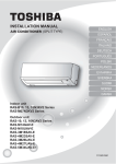
INSTALLATION MANUAL
AIR CONDITIONER (SPLIT TYPE)
ENGLISH
ESPAÑOL
FRANÇAIS
ITALIANO
DEUTSCH
PORTUGUÊS
POLSKI
ČESKY
PУCСКИЙ
HRVATSKI
MAGYAR
TÜRKÇE
NEDERLANDS
ΕΛΛΗΝΙΚΑ
Indoor unit
RAS-(B) 10, 13, 18UFV Series
SVENSKA
SUOMI
NORSK
Outdoor unit
RAS-10, 13, 18SAV Series
RAS-M14GAV-E
RAS-M18GAV-E
RAS-3M18SAV-E
RAS-3M26GAV-E1
RAS-4M23SAV-E
RAS-4M27GAV-E1
RAS-5M34UAV-E
DANSK
ROMÂNĂ
БЪЛГАРСКИ
EESTI
LATVISKI
SLOVENČINA
SLOVENŠČINA
Toshiba 1112150201 (CVF)
INSTALLATION DIAGRAM OF INDOOR AND OUTDOOR UNITS
Do not allow the drain hose to get
slack.
70 mm or more
1
Air filter
Installation plate
Cut the piping
hole sloped
slightly.
50 mm or more
50 mm or more
6 Filter
Make sure to run the drain hose
sloped downward.
5 Filter
The auxiliary piping can be
connected to the left, rear left, rear
right, right, bottom right or bottom
left.
3 Batteries
Shield pipe
Right
2
Wireless remote control
8
Pan head
wood screw
4 Remote control holder
Left
Rear right
Bottom right
Rear left
Bottom left
Vinyl tape
Apply after carrying
out a drainage test.
9 Insulation sheet
600 mm or more only
when unobstructed
to the front and both
sides.
Remark :
(D)
100
CAUTION
In case of right or left piping
mm
or
Extension
drain hose
(Not available,
provided by installer)
re
mo
(B)
Install in rooms that are 13 m3 or larger.
If a leak of refrigerator gas occurs
inside the room, an oxygen deficiency
can occur.
600
or
Cut dot-line area
mo
re
Fixing bolt arrangement of outdoor unit
RAS-10, 13, 18SAV Series
Parts name
Q’ty
A
Refrigerant piping
Liquid side : ∅6.35 mm
Gas side : ∅9.52 mm
(RAS-(B) 10, 13UFV Series)
: ∅12.7 mm
(RAS-(B) 18UFV Series)
One
each
• Secure the outdoor unit with fixing bolts and nuts if the unit is likely to be exposed
to a strong wind.
• Use ∅8 mm or ∅10 mm anchor bolts and nuts.
• If it is necessary to drain the defrost water, attach drain nipple and cap water proof
to the bottom plate of the outdoor unit before installing it.
108 mm
125 mm
28 mm
Air inlet
320 mm
25
mm
Part
code
Putty, PVC tapes
mm
(A)
Optional Installation Parts
C
8 mm thick heat resisting
polyethylene foam
Saddle
(C)
600
B
or m
100
mm
or
mo
re
• Detail of accessory and installation
parts can see in the accessory sheet.
Pipe insulating material
(polyethylene foam, 8 mm thick)
ore
mm
1
One
each
* Drain nipple and cap
water proof are packed
in outdoor unit.
102 mm
When installing the outdoor unit,
leave open in at least two of direction
(A), (B), (C) and (D) shown in the
figure on the right.
86 mm
7 Mounting screw
Insulate the refrigerant pipes
separately with insulation, not
together.
Air outlet
90 mm
600 mm
Drain outlet
X When using a multi-system outdoor unit is used, refer to the installation manual
provided with the model concerned.
3
Toshiba 1112150201 (EN)
INDOOR UNIT
Mounting the installation plate and screw position
Installation Place
• A place which provides the spaces around the indoor unit as shown in the
diagram.
• A place where there are no obstacles near the air inlet and outlet.
• A place which allows easy installation of the piping to the outdoor unit.
• A place which allows the front panel to be opened.
(Unit : mm)
(700)
150
230
EN
(600)
• Direct sunlight to the indoor unit’s wireless receiver should be avoided.
• The microprocessor in the indoor unit should not be too close to RF
noise sources.
(For details, see the owner’s manual)
m
90
560
272
on the wall
1. Securely fit the installation plate onto the wall by screwing it in the upper
and lower parts to hook up the indoor unit.
2. To mount the installation plate on a concrete wall with anchor bolts, use
the anchor bolt holes as illustrated in the below figure.
3. Install the installation plate horizontally in the wall.
45
PT
PL
CZ
RU
Installation plate
(Keep horizontal direction)
on
pti
ce
ran
60
DE
When the installation plate is directly mounted
Re
Remote
control
IT
Floor
7
45
90
(20
5)
15
7m
m
Wall
15
(Top view)
7
FR
15
• A place where there are no obstacles such as a curtain that may block the
signal from the remote control.
• Do not install the remote control in a place exposed to direct sunlight or
close to a heating source such as a stove.
• Keep the remote control at least 1 m apart from the nearest TV set or
stereo equipment (This is necessary to prevent image disturbances or
noise interference).
• The location of the remote control should be determined as shown below.
(Side view)
ES
15
Remote control
Indoor unit
670
590
CAUTION
Anchor bolt
CR
ge
Remote control
Reception range
Projection
15 mm or less
∅5 mm hole
* : Axial distance
7
Cutting a Hole and Mounting
Installation Plate
(Side piping)
CAUTION
GR
Failure to firmly install the unit may result in personal injury and property
damage if the unit falls.
SV
• In case of block, brick, concrete or similar type walls, make ∅5 mm holes
in the wall.
• Insert clip anchors for appropriate mounting screws 7.
60
45
DK
RO
60
100
(Bottom piping)
100
FI
NO
45
45
45
100
TR
NL
Clip anchor
(local parts)
Cutting a hole
(Rear piping)
Mounting screw
∅4 mm x 25 s
HU
BG
: Pipe hole (∅65 mm)
EE
70
LV
1. After determining the pipe hole position, drill the pipe hole (∅65 mm) at a
slight downward slant to the outdoor side.
SK
NOTE
• When drilling a wall that contains a metal lath, wire lath or metal plate, be
sure to use a pipe hole brim ring sold separately.
SI
4
Toshiba 1112150201 (EN)
2. Put water in the drain pan and make sure that the water is drained out of
doors.
3. When connecting extension drain hose, insulate the connecting part of
extension drain hose with shield pipe.
How to Install Indoor Unit
1. Remove the air inlet grille. Open the air inlet grille and remove the strap.
2. Remove the front panel (Remove the 4 screws).
Shield pipe
Extension drain hose
Front panel
Drain hose
Hook
Inside the room
CAUTION
Arrange the drain pipe for proper drainage from the unit.
Improper drainage can result in dew-dropping.
Air inlet grille
Wiring connection
Wiring of the connection cable is necessary to remove the front panel.
1. Remove the terminal cover and cord clamp.
2. Insert the connecting cable (according to the local rule) into the pipe hole
on the wall.
3. Take out the connecting cable through the cable slot on the rear panel so
that it protrudes about 50 cm from the front.
4. Insert the connecting cable fully into the terminal block and secure it
tightly with screws.
5. Tightening torque : 1.2 N·m (0.12 kgf·m)
6. Secure the connecting cable with the cord clamp.
7. Fix the terminal cover, install the front panel and grille inlet.
Layout of connection piping
100
542
58
85
6
112
148
64
40
85
49
40
R45
29
6
108
12
CAUTION
0
• Be sure to refer to the wiring system diagram labeled inside the front
panel.
• Check local electrical cords and also any specific wiring instructions or
limitations.
Hook
47
Terminal cover
210
163
Connection piping
49
Terminal
block
Screw
Earth line
Treatment of piping connection
1) Check the flare nut connections for the gas leak with a gas leak detector
or soap water.
2) To prevent gap in slit, fasten top and bottom with tape.
3) Slit is covered with tape.
4) Fasten with supplied Insulate sheet to prevent gap on the top of slit.
Screw
Cord clamp
Earth screw
Gas leak check
Tape
Tape
110 mm
Earth line
20 mm
Slit
430 mm
9 Insulation sheet
10 mm
50 mm
Drainage
1. Run the drain hose sloped downwards.
NOTE
Stripping length of the connecting cable
• The hole should be made at a slight downward slant on the outdoor side.
Do not form the
drain hose into
a wavy shape.
Do not rise the
drain hose.
Do not put the
drain hose end
into water.
NOTE
• Use stranded wire only.
• Wire type : H07RN-F or 60245 IEC66 (1.0 mm2 or more)
Do not put the
drain hose end in
the drainage ditch.
5
Toshiba 1112150201 (EN)
Mounting directly on the floor.
1) Fix the leg of indoor unit on the floor with 2 mounting screws.
2) Fix the upper part of indoor unit on the wall with 4 mounting screws.
For prevent dewfall
(Floor installation)
Wall burying mode
EN
Slit
ES
2. Wall hole size
Wall hole size should be enough to keep the distance with indoor unit as
shown in the following figure.
6 screw
(M4 x 25L)
(Front view)
(Unit : mm)
FR
(Side view)
70 or more
NOTE
240 to 250
IT
800 or more
• In case the plinth is fixed to the wall, please make sure to cut out the slit
on the left and right side of the main part.
(600)
(700)
Wall
Cut dot-line area
670 or more
Wall
DE
20 to 30
PL
Floor
50 or more
1) Fix the installation plate on the wall with 4 mounting screws.
2) Hook the indoor unit on the installation plate.
3) Fix the upper part of indoor unit on the wall with 4 mounting screws.
(Rear screws potion)
340
15
560
272
4 screw
(M4 x 25L)
1000 mm or less
670
240
288
15
670
CR
(Field supply)
(Field supply)
230
RU
HU
(Side view)
150
10
40
CZ
Floor
3. Installation using the supporting plate
• To install into the existing wall hole, if it is impossible to keep 20-30 mm
of depth, use the supporting plate for securing the distance.
• Arrange the screw positions and supporting plate as shown in the
figure.
• Be sure to switch to wall burying mode.
Installation on the wall
(Wall installation)
50 or more
Indoor unit
PT
(Unit : mm)
: Screw holes
4. In case of lattice establishment
• Follow the following figure, make sure to keep enough distance
between lattice, frame and wall.
• Be sure to switch to wall burying mode.
• The lattice should be make of wood.
• Between the air inlet and outlet, should be devided with partition board.
• Be sure to establish the open part for RECEIVER.
• The open part of lattice must be opens 70 % or more of the wall hole.
• The open part of lattice must be arranged uniformly.
4 screw
(M4 x 25L)
CAUTION
(Top view)
Make sure to fix it at a designated position with the screws.
Failure may result the damage of piping by the turning over of a set.
(Unit : mm)
TR
NL
GR
SV
FI
NO
DK
RO
BG
Concealed Installation
Partition board
The special method to install the indoor unit bury in the wall is shown here.
Please make sure to change to wall burying mode.
1. To switch to the wall burying mode
To switch to the wall burying mode, press and hold AIR OUTLET
SELECT button for 20 seconds.
- When the operation set up and 5 beep sounds. Then indication at
Temperature indicator will light up for 5 seconds.
- To cancel, press AIR OUTLET SELECT button for 20 seconds then, 5
beep sounds. Then indication at Temperature indicator will blinks for 5
seconds.
- To prevent dewfall, above plate angle should be narrow.
EE
LV
SK
SI
6
Toshiba 1112150201 (EN)
(Front view)
(Side view)
70 or more
Opening for receiver
800 or more
Partition board
50 or more
20 to 30
Partition board
500
670 or more
140
Opening for receiver
50 or more
OUTDOOR UNIT
• When using a multi-system outdoor unit refer to the installation manual
provided with the model concerned.
Draining off the Water
from the Outdoor Unit
Installation Place
• If it is necessary to drain off the water from the outdoor unit, install two
water-proofing rubber caps and a drain nipple.
• A place which provides enough spaces around the outdoor unit as shown
in the diagram.
• A place which can bear the weight of the outdoor unit and does not allow
an increase in noise level and vibration.
• A place where the operation noise and discharged air do not disturb your
neighbors.
• A place which is not exposed to a strong wind.
• A place free of a leakage of combustible gases.
• A place which does not block a passage.
• When the outdoor unit is to be installed in an elevated position, be sure to
secure its feet.
• This air conditioner accepts a connection piping length from 2 m to 20 m.
• There is no need to add refrigerant as long as the length of the
connection piping is 15 m or less.
• You will need to add 20 g of refrigerant per meter of added connection
piping for installation requiring connection piping to be between 16 m to
20 m.
• An allowable height level is up to 10 m.
• A place where the drain water does not cause any problems.
Water-proof rubber caps
(supplied with the outdoor unit)
Base plate
Drain nipple
Precautions about Installation in Regions
with Snowfall and Cold Temperatures
Refrigerant Piping Connection
Flaring
• Do not use the supplied drain nipple for draining water. Drain the water from
all the drain holes directly.
• To protect the outdoor unit from snow accumulation, install a holding frame,
and attach a snow protection hood and plate.
* Do not use a double-stacked design.
1. Cut the pipe with a pipe cutter.
2. Deburr the inside of the pipe at its end.
Take steps to ensure that the removed burrs will not enter the pipe.
3. Remove the flare nuts provided with the indoor and outdoor units, and
insert them into the pipe.
4. Flare the pipe.
The projection margin of the pipe must be checked.
5. Check that the flare has the appropriate shape.
Snow protection plate
Front
Snow protection hood
Install at least 50 cm
above the snow
accumulation line.
At least 50 cm
Anchor bolts
Snow accumulation line
Obliquity
90
Roughness
Warp
Holding frame
B
CAUTION
C
A
1. Install the outdoor unit in a location where there are no obstructions
near its air intake or air outlet.
2. When the outdoor unit is installed in a place that is always exposed to
strong winds like on the coast or on a high story of a building, secure
the normal fan operation using a duct or a wind shield.
3. Especially in windy areas, install the unit to prevent the admission of
wind.
4. Installation in the following places may result in trouble.
Do not install the unit in such places.
• A place full of machine oil.
• A saline-place such as the coast.
Strong
• A place full of sulfide gas.
wind
• A place where high-frequency
waves are likely to be generated,
such as from audio equipment, welders, and medical equipment.
Die
Pipe
Pipe
A
Outside
diameter
Thickness
Rigid
(clutch type)
R410A tool
B
Imperial
(wing nut
type)
R410A tool
Flare Nut
C
Tighten torque
mm
mm
mm
mm
mm
mm
N·m
kgf·m
6.35
0.8
0 to 0.5
1.5 to 2.0
9.1
17
14 to 18
1.4 to 1.8
9.52
0.8
0 to 0.5
1.5 to 2.0
13.2
22
33 to 42
3.3 to 4.2
12.7
0.8
0 to 0.5
2.0 to 2.5
16.6
26
50 to 62
5.0 to 6.2
7
Toshiba 1112150201 (EN)
• Tightening torque for connection of flare pipe
The pressure of R410A is higher than R22
(Approx. 1.6 times). Therefore securely
tighten the flare pipes which connect the
outdoor unit and the indoor unit with the
specified tightening torque using a torque
wrench. If any flare pipe is incorrectly
connected, it may cause not only
a gas leakage but also trouble in the
refrigeration cycle.
Flare at
indoor unit side
Gas side
(∅12.70 mm)
50 to 62 N·m
(5.0 to 6.2 kgf·m)
Gas side
(∅9.52 mm)
33 to 42 N·m
(3.3 to 4.2 kgf·m)
Liquid side
(∅6.35 mm)
14 to 18 N·m
(1.4 to 1.8 kgf·m)
Service port
14 to 18 N·m
(1.4 to 1.8 kgf·m)
1. Remove the valve cover, the electric parts cover and the cord clamp from
the outdoor unit.
2. Connect the connecting cable to the terminal as identified by the matching
numbers on the terminal block of indoor and outdoor unit.
3. Insert the power cord and the connecting cable fully into the terminal
block and secure it tightly with screws.
4. Use vinyl tape, etc. to insulate the cords which are not going to be used.
Locate them so that they do not touch any electrical or metal parts.
5. Secure the power cord and the connecting cable with the cord clamp.
6. Attach the electric parts cover and the valve cover on the outdoor unit.
Evacuating
After the piping has been connected to the indoor unit, you can perform
vacuuming together at once.
VACUUMING
Evacuate the air in the connecting pipes and in the indoor unit using a
vacuum pump. Do not use the refrigerant in the outdoor unit. For details,
see the manual of the vacuum pump.
Using a vacuum pump
Electrical Work
Be sure to use a vacuum pump with counter-flow prevention function so
that inside oil of the pump does not flow backward into pipes of the air
conditioner when the pump stops.
(If oil inside of the vacuum pump enters the air conditioner, which use
R410A, refrigeration cycle trouble may happen.)
RAS-(B)10UFV
series
Model
Maximum running
current
RAS-(B)13UFV
series
8.5A
RAS-(B)18UFV
series
11.0A
Power cord
H07RN-F or 60245 IEC66 (1.5 mm2 or more)
Connecting cable
H07RN-F or 60245 IEC66 (1.0 mm2 or more)
10
10
40
30
Vacuum pump adapter for
counter-flow prevention
(For R410A only)
NL
L N
10
Connecting pipe
40
30
Power cord
Connecting cable
Power cord
Vacuum
pump
FI
RAS-10SAVR-A, RAS-18SAV-E
1 2 3
3
L
N
L N
10
Service port (Valve core (Setting pin))
40
30
Packed valve at liquid side
NO
10
2
10
1
10
Terminal
block
Packed valve at gas side
GR
SV
Earth line
Connecting cable
HU
TR
1 2 3
Terminal
block
Charge hose
(For R410A only)
CZ
CR
Stripping length of the connecting cable
10
Handle Lo
PL
16A
Handle Hi
(Keep full closed)
Charge hose
(For R410A only)
IT
12.0A
X When using a multi-system outdoor unit is used, refer to the installation
manual provided with the model concerned.
Manifold valve
FR
RU
Plug socket & fuse
rating
Pressure gauge
ES
PT
220–240V ~ 50Hz 220–240V ~ 50Hz 220–240V ~ 50Hz
220–230V ~ 60Hz 220–230V ~ 60Hz 220–230V ~ 60Hz
Power source
EN
DE
1. The supply voltage must be the same as the rated voltage of the air
conditioner.
2. Prepare the power source for exclusive use with the air conditioner.
1. Connect the charge hose from the manifold valve to the service port of the
packed valve at gas side.
2. Connect the charge hose to the port of the vacuum pump.
3. Open fully the low pressure side handle of the gauge manifold valve.
4. Operate the vacuum pump to start evacuating. Perform evacuating for
about 15 minutes if the piping length is 20 meters (15 minutes for 20
meters) (assuming a pump capacity of 27 liters per minute). Then confirm
that the compound pressure gauge reading is –101 kPa (–76 cmHg).
5. Close the low pressure side valve handle of the gauge manifold valve.
6. Open fully the valve stem of the packed valves (both gas and liquid
sides).
7. Remove the charging hose from the service port.
8. Securely tighten the caps on the packed valves.
–101 kPa (–76 cmHg)
m
4m
Wiring Connection
Flare at
outdoor unit side
Compound pressure gauge
Hexagon wrench
is required.
40
30
DK
Earth line
CAUTION
Connecting cable
• KEEP IMPORTANT 5 POINTS FOR PIPING WORK.
(1) Take away dust and moisture (inside of the connecting pipes).
(2) Tighten the connections (between pipes and unit).
(3) Evacuate the air in the connecting pipes using a VACUUM PUMP.
(4) Check gas leak (connected points).
(5) Be sure to fully open the packed valves before operation.
Power cord
Connecting cable
Power cord
CAUTION
BG
• Wrong wiring connection may cause some electrical parts burn out.
• Be sure to comply with local rule on running the wire from indoor unit
to outdoor unit (size of wire and wiring method, etc.).
• Every wire must be connected firmly.
• If incorrect or incomplete wiring is carried out, it will cause an ignition
or smoke.
• Prepare the power supply for exclusive use with the air conditioner.
• This product can be connected to the mains.
Connection to fixed wiring : A switch which disconnects all poles and
has a contact separation of at least 3 mm must be incorporated in the
fixed wiring.
Packed valve handling precautions
• Open the valve stem until it touches the stopper. Once it is in contact with
the stopper, refrain from applying any more force than is necessary.
• Securely tighten the valve stem cap with torque in the following table:
RO
EE
LV
SK
SI
8
Toshiba 1112150201 (EN)
OTHERS
Unit B setup.
Press and hold MODE button for more than 20 seconds.
When A setup changed to B setup : 5 beeps will sound and operation
lamp blinks for 5 seconds.
When B setup changed to A setup : 5 beep will sound.
Gas Leak Test
Test Operation
To switch the TEST RUN (COOL) mode, press OPERATION button for 10
seconds (The beeper will make a short beep).
Check places for flare nut connection
(Indoor unit)
Valve cover
• Check the flare nut
connections for the gas
leak with a gas leak
detector or soap water.
Check places for the outdoor unit.
Auto Restart Setting
Setting of Remote Control
Selector Switch
This product is designed so that, after a power failure, it can restart
automatically in the same operating mode as before the power failure.
When two indoor units are installed in the separated rooms, it is not
necessary to change the selector switches.
Information
The product are shipped with Auto Restart function in the off position.
Turn it on as required.
Remote control selector switch
• When two indoor units are installed in the same room or adjacent two
rooms, if operating a unit, two units may receive the remote control
signal simultaneously and operate. In this case, the operation can
be preserved by setting either one indoor unit or remote control to B
setting (Both are set to A setting in factory shipment).
• The remote control signal is not received when the settings of indoor
unit and remote control are different.
• There is no relation between A setting/B setting and A room/B room
when connecting the piping and cables.
How to set the Auto Restart
1. Press and hold OPERATION button on the indoor unit for 3 seconds to set
the operation (3 beep sound and OPERATION lamp blink 5 time/sec for 5
seconds).
2. Press and hold OPERATION button on the indoor unit for 3 seconds to
cancel the operation (3 beep sound but OPERATION lamp does not blink).
• In case of ON timer or OFF timer are set, it dose not activate.
Remote Control A-B Selection
To separate using of remote control for each indoor unit in case of 2 air
conditioners are installed nearly.
Remote Control B Setup.
button on the Remote Control by the tip of the pencil.
1. Push and hold
“00” will be shown on the display.
during pushing
. “B” will show on the display and “00” will
2. Press
disappear and the air conditioner will turn OFF. The Remote Control B is
memorized.
Note : 1. Repeat above step to reset Remote Control to be A.
2. Remote Control A has not “A” display.
3. Default setting of Remote Control from factory is A.
“B” Display
“00” Display
PRESET
FAN
9
Toshiba 1112150201 (EN)
1112150201
Toshiba 1112150201 (CVB)