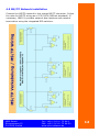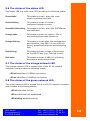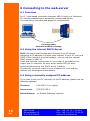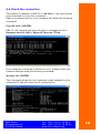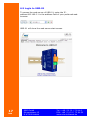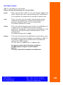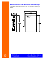
1
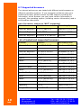
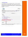
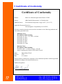
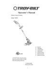
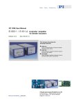
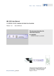
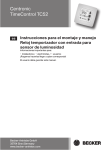
Installation Manual
Universal
BACnet
Router
UBR-01
Rev 2.4, 28.09.2011
List of Contents
1 Revision History ................................................................ 5
2 Welcome to UBR-01 .......................................................... 6
2.1 General Information ..................................................... 6
2.2 Key features ............................................................... 6
2.3 Unique Key feature ...................................................... 6
2.4 Other BACnet products from MBS .................................. 6
2.5 Product Support ............................................................. 7
2.6 Copyright ...................................................................... 7
3 Connectors and Control Elements ........................................ 8
3.1 LED............................................................................ 8
3.2 Connector configuration................................................ 9
3.3 DIP-Switches ............................................................ 10
4 Introduction ................................................................... 11
4.1 Required tools ........................................................... 11
4.2 The concept of UBR-01 configuration............................ 11
4.3 Electrical installation .................................................. 11
4.4 Ethernet Network installation ...................................... 11
4.5 MS/TP Network installation ......................................... 12
5 Start-up-phase ............................................................... 13
5.1 Resetting UBR-01 ...................................................... 13
5.2 The reset phase ......................................................... 13
5.3 The states of the power LED ....................................... 13
5.4 The states of the MS/TP TxD LED ................................. 13
5.5 The states of the MS/TP RxD LED ................................ 13
5.6 The states of the status LED ....................................... 14
5.7 The states of the orange network LED .......................... 14
5.8 The states of the green network LED ............................ 14
3
28
MBS GmbH
Römerstrasse 15
D-47809 Krefeld
Tel.: +49 / 21 51 / 72 94-0
FAX: +49 / 21 51 / 72 94-50
www.mbs-software.de
6 Connecting to the web-server............................................15
6.1 Overview...................................................................15
6.2 Using the internal DHCP-Server ...................................15
6.3 Using a manually assigned IP-address ..........................15
6.4 Check the connection ..................................................16
6.5 Login to UBR-01 .........................................................17
6.6 User-levels ................................................................18
6.7 Supported browsers....................................................19
6.8 Next steps .................................................................20
7 Certificate of Conformity ...................................................23
8 Technical Specifications ....................................................24
9 Dimensions and Mechanical Drawings .................................25
The MBS logo is a registered trademark of MBS GmbH.
BACnet is a registered trademark of ASHRAE, Inc.
MBS GmbH
Römerstrasse 15
D-47809 Krefeld
Tel.: +49 / 21 51 / 72 94-0
FAX: +49 / 21 51 / 72 94-50
www.mbs-software.de
4
1 Revision History
This table shows the revision history of this document.
Datum
5
28
Autor
Änderungen
08.10.2008 Frank Schubert
Revision 1.0
Initial version
01.12.2008 Frank Schubert
Revision 1.1
Added Connectors and Control
Elements
Added Mechanical Drawings
15.12.2008 Frank Schubert
Revision 1.2
Added Certificate of Conformity Added
Support Information Added LED
Assignment Added Connector
Assignment
25.05.2009 Frank Schubert
Revision 2.2
Updated list of supported browsers
27.05.2011 ANE
Revision 2.3
Layout revision
28.09.2012 ANE
Revision 2.4
New mechanical drawing
MBS GmbH
Römerstrasse 15
D-47809 Krefeld
Tel.: +49 / 21 51 / 72 94-0
FAX: +49 / 21 51 / 72 94-50
www.mbs-software.de
2 Welcome to UBR-01
2.1 General Information
Thank you for purchasing the UBR-01!
This device is designed for highly reliable and easy-to-install routing
functions in BACnet networks.
2.2 Key features
Supported BACnet Data-Link-Layers: BACnet/IP (Annex-J),
BACnet/Ethernet (ISO8802-2 Type 1 on ISO8802-3), MS/TP-Master
BBMD and FD mode
Device Profile B-ASC functionality
Extra BIBBS: DS-RPM-B, DS-WPM-B
Full Segmentation support
Network: 10/100 MBit/s Auto-sensing RJ-45 connector
2.3 Unique Key feature
Storage Space: 150MB space for Factory and 50MB for project files
This allows persistent storage of documents, where you need them:
Directly within the device accessible by a standard web-browser.
You can store any file-type to provide on-site documentation, backup
project documentation or leave messages to other technicians.
2.4 Other BACnet products from MBS
BACnet OPC-Server: The industries leading software to bridge the
gap between BACnet-networks and OPC-Client stations.
BACnet OPC-Client: Connect to OPC-Server and provide the data as
a BACnet-Server.
BACnet Universal-Gateways: Connect other communication
protocols to BACnet, or connect BACnet devices to other
communication protocols.
BACnet Test Framework: Test your devices on conformance to
BACnet, use it as a project tool to perform script-based testing on
key-names, description-texts or create project-documentations or
use this software for your companies’ quality assurance process.
MBS GmbH
Römerstrasse 15
D-47809 Krefeld
Tel.: +49 / 21 51 / 72 94-0
FAX: +49 / 21 51 / 72 94-50
www.mbs-software.de
6
BACnet Trainings and Consulting: Learn the basics of BACnet,
specifying BACnet projects or learn how to develop BACnet
implementations.
BACnet Data-logger: Log- and analyze your BACnet-network traffic
within your project.
BACnet Data-server: Control and monitor the energy efficiency or
provide remote access to your BACnet-project.
BACnet Protocol stacks: From small MS/TP implementations up to
large B-BC BACnet/IP devices, our highly efficient and reliable
BACnet protocol stack BAC-App supports easy BACnet development.
2.5 Product Support
Our product support is available from
Monday – Friday 9.00 a.m. – 4.00 p.m. MET/MEST
(except public holidays).
Telephone: +49 / 21 51 / 72 94 – 0
Telefax: +49 / 21 51 / 72 94 – 50
E-Mail: [email protected]
Homepage: www.mbs-software.de
2.6 Copyright
© 2008-2012 MBS GmbH, All rights reserved
7
28
MBS GmbH
Römerstrasse 15
D-47809 Krefeld
Tel.: +49 / 21 51 / 72 94-0
FAX: +49 / 21 51 / 72 94-50
www.mbs-software.de
3 Connectors and Control Elements
The following picture shows the front panel of UBR-01.
PE
Network
Link/Activity
1
Power
MS/TP
10/100 MBit/s
DIP-Switches LED
3
4
5
6
2
3.1 LED
UBR-01 provides 6 LED (Light Emitting Diodes) to display the system
status.
1 Link/Activity: This green LED shows the status of the network
connection and activity.
2 10/100 MBit/s: This yellow LED shows the connection speed to
the network.
3 Status: This LED is a multi-color LED showing the system
status of UBR-01.
4 MS/TP TxD: This yellow LED flashes, when UBR-01 transmits
data on the MS/TP network.
5 MS/TP RxD: This yellow LED flashes, when UBR-01 receives
data from the MS/TP network.
6 Power: This green LED shows the status of the power
connection.
MBS GmbH
Römerstrasse 15
D-47809 Krefeld
Tel.: +49 / 21 51 / 72 94-0
FAX: +49 / 21 51 / 72 94-50
www.mbs-software.de
8
3.2 Connector configuration
PE:
This connector is used to connect Potential Earth to
UBR-01, please follow the rules of VDE100 and
other electrical specifications for cabinet mounting
and installations.
Network:
This connector is a RJ-45 connector to connect
UBR-01 to Ethernet networks. If you plan to
connect your Notebook-PC for configurations, use
the crossover-cable which is part of the UBR-01
package. If you connect to a network, please use a
standard CAT5e or similar cord (not included in the
UBR-01 package).
Power:
This two-pin connector is used to connect to the
external power-supply (not included in the UBR-01
package). Please refer to the technical specification
at the end of this manual.
This connector is polarity independent.
MS/TP:
This connector connects to the BACnet MS/TP
network.
Connector assignment from left to right:
9
28
B+:
This connector provides the noninverting
input of the EIA-485
transceiver.
A-:
This connector provides the inverting
input to the EIA-485 transceiver.
AGND:
This connector provides the groundconnection
to the EIA-485 network.
Shield:
This connector provides the connection
to the cable-shield. This connector is
connected to PE (Potential Earth).
MBS GmbH
Römerstrasse 15
D-47809 Krefeld
Tel.: +49 / 21 51 / 72 94-0
FAX: +49 / 21 51 / 72 94-50
www.mbs-software.de
3.3 DIP-Switches
The integrated DIP-Switches allow setup of Network-Bias and
Network-Termination in the MS/TP network.
Note: A DIP-Switch is active, when the switch is set to the
upper position (marked with “on”), by default, all DIPSwitches
are inactive (off).
The Network Bias resistors shall always be used together.
Always switch on or off both switches, never switch on only
one switch while the other switch is turned off!
Connector assignment from left to right:
S1 Network Bias:
S1 and S2 provide 560 Ohms Network
Bias resistors. A segment in MS/TP shall
contain at least one but not more than
two pairs of Network Bias resistors,
preferable at the end(s) of the segment.
S2 Network Bias:
Same as S1, always use S1 and S2
combined!
S3 Termination:
Each end of the segments in MS/TP
network require termination, this
connector provides a 120 Ohms
termination resistor.
MBS GmbH
Römerstrasse 15
D-47809 Krefeld
Tel.: +49 / 21 51 / 72 94-0
FAX: +49 / 21 51 / 72 94-50
www.mbs-software.de
10
4 Introduction
4.1 Required tools
To mount UBR-01 you will need the following tools:
- Screwdriver flat approx. 3 mm (included in package)
- Crossover-network cable (included in package)
- This manual (included in package)
- Notebook-PC
with at least the following specifications:
Integrated or external network-interface-card
Web-Browser installed (refer to the list of supported
browsers)
Adobe Acrobat Reader installed
4.2 The concept of UBR-01 configuration
UBR-01 provides an integrated and powerful web-server for easy
configuration, this installation manual describes all necessary steps
to access the web-server.
All related documentation including the configuration manual is
stored in the help-directory of the web-server and can be accessed
using the Adobe Acrobat Reader.
4.3 Electrical installation
Connect UBR-01 to a power-supply, which meets the technical
specifications. International power-supply is provided as an option
module to UBR-01. Warranty will be void, if UBR-01 will be connected
to a power-supply outside the technical specifications.
Warranty will be void, if the UBR-01 case is opened.
No user-accessible parts inside.
4.4 Ethernet Network installation
Connect the Ethernet network cable (RJ-45 connector) to the UBR-01
module. Standard CAT 5 UTP or STP cables can be used.
Avoid parallel runs with power (e.g. motor) cables.
Don’t connect the UBR-01 module to the network before you
have configured the device!
Use the included crossover-cable for configuration.
11
28
MBS GmbH
Römerstrasse 15
D-47809 Krefeld
Tel.: +49 / 21 51 / 72 94-0
FAX: +49 / 21 51 / 72 94-50
www.mbs-software.de
4.5 MS/TP Network installation
Connect the MS/TP network to the orange MS/TP connector. Follow
the rules for MS/TP wiring as of 135-2004 (BACnet-standard). If
necessary, UBR-01 provides network bias resistors and network
termination using the integrated DIP-switches.
MBS GmbH
Römerstrasse 15
D-47809 Krefeld
Tel.: +49 / 21 51 / 72 94-0
FAX: +49 / 21 51 / 72 94-50
www.mbs-software.de
12
5 Start-up-phase
After applying the power UBR-01 directly starts operation. The
Device is designated for a permanent runtime 24/7, so no additional
power switch needs to be activated. If you need to disconnect UBR01 from the power-supply, simply remove the green power
connector.
5.1 Resetting UBR-01
Reset: Press and release the reset-switch to reset
the device. The status LED will switch to red
for approx. 2 seconds, after this, the reset is
performed. In the reset phase the status LED
shows orange color statically.
DHCP: To activate the DHCP-Server, press and hold
the reset switch for more than 5 seconds but
not longer than 10 seconds. The status LED
starts blinking green/red alternating when in
DHCP-mode.
Factory-Reset: To perform a factory reset, press and hold the
reset switch for at least 15 seconds. The
status LED starts blinking orange. After
copying the default configuration, a reset is
performed.
5.2 The reset phase
UBR-01 approx. needs 25s to perform a reset.
While in reset mode, UBR-01 performs no MS/TP or Network activity.
5.3 The states of the power LED
The power LED shows green, if 24V DC power is connected. The LED
is switched off, if the power-supply is missing.
5.4 The states of the MS/TP TxD LED
The MS/TP TxD flashes in yellow color, if data is transmitted to the
MS/TP network.
5.5 The states of the MS/TP RxD LED
The MS/TP RxD flashes in yellow color, if data is received from the
MS/TP network.
13
28
MBS GmbH
Römerstrasse 15
D-47809 Krefeld
Tel.: +49 / 21 51 / 72 94-0
FAX: +49 / 21 51 / 72 94-50
www.mbs-software.de
5.6 The states of the status LED
The status LED is a multi-color LED providing the following states:
Green static:
This state is shown, when the reset
switch is pressed and held.
Green blinking:
This state is shown in normal /
configured operation mode.
Green/Red Alternating: This state is shown, when the DHCPServer
was activated.
Orange static:
This state is shown for approx. 25s in
the starting phase after power-up.
Orange blinking:
This state is shown after the startupphase
and identifies, that UBR-01 runs with the
factory preset and requires commissioning
first.
Red blinking:
This state is shown in case of Bus errors
on the MS/TP bus (e.g. Framing errors).
Red static:
This state is shown if UBR-01 is flushing
files before performing a reset.
5.7 The states of the orange network LED
The orange network LED is located right of the RJ-45 network
connector and provides the following states:
LED off identifies a 10MBit/s connection
LED on identifies a 100MBit/s connection
5.8 The states of the green network LED
The green network LED is located left of the RJ-45 network connector
and provides the following states:
LED off identifies no Link
LED on identifies Link established
LED blinking identifies activity
MBS GmbH
Römerstrasse 15
D-47809 Krefeld
Tel.: +49 / 21 51 / 72 94-0
FAX: +49 / 21 51 / 72 94-50
www.mbs-software.de
14
6 Connecting to the web-server
6.1 Overview
An IP / web-based connection between UBR-01 and your NotebookPC must be established to access the internal web-server.
The web-server provides web-pages for configuration.
Crossover-cable
(included in UBR-01 package)
6.2 Using the internal DHCP-Server
DHCP=Dynamic Host Configuration Protocol is an IP-service
assigning an IP-address to clients upon request. If your PC runs as a
DHCP-Client (which is a typical setting), you can use the internal
DHCP-server of UBR-01.
Press and hold the reset-switch for more than 5 seconds but not
longer than 10 seconds. As soon as the status LED will blink
green/red alternating, the DHCP-server is active.
Connect the crossover-cable to your notebook-PC now and the
address will be assigned automatically.
6.3 Using a manually assigned IP-address
If you plan to set your PC manually to the IP-address, please use the
following settings:
IP-address:
192.168.0.2 (or higher)
Subnet-mask:
255.255.255.0
Default-Gateway: no Default-Gateway required
15
28
MBS GmbH
Römerstrasse 15
D-47809 Krefeld
Tel.: +49 / 21 51 / 72 94-0
FAX: +49 / 21 51 / 72 94-50
www.mbs-software.de
6.4 Check the connection
The default IP-address of UBR-01 is 192.168.0.1, you may use the
ping-command to check the connection.
Open a command-shell on your notebook and enter the following
command:
Ping 192.168.0.1 <ENTER>
UBR-01 will respond and ping will show a message like this:
Response from 192.168.0.1: Bytes=32 Time=1ms TTL=64
If the response is missing or shows an error, please check your
network settings using the following command:
ipconfig / ALL <ENTER>
This command shows the list of network-cards installed in your
notebook-PC and will show the IP-configuration.
MBS GmbH
Römerstrasse 15
D-47809 Krefeld
Tel.: +49 / 21 51 / 72 94-0
FAX: +49 / 21 51 / 72 94-50
www.mbs-software.de
16
6.5 Login to UBR-01
To access the web-server of UBR-01, enter the IPaddress192.168.0.1 in the address field of your preferred webbrowser.
UBR-01 will show the web-server start screen.
17
28
MBS GmbH
Römerstrasse 15
D-47809 Krefeld
Tel.: +49 / 21 51 / 72 94-0
FAX: +49 / 21 51 / 72 94-50
www.mbs-software.de
6.6 User-levels
UBR-01 provides four user levels.
Please note that all passwords are case-sensitive!
guest:
When connecting to UBR-01, you are already logged in as
guest. Guest-user may read all settings but modification
is not allowed. No password is required for guest-user.
user:
This is the user-level to modify most settings except
changing the passwords, upload documentations or
perform a backup/restore of the configuration.
The default password is: user
admin:
This is the administrator level to allow all modifications of
a regular user, but additionally allows changing
passwords, uploading or removing documentations to the
web-server and performing a backup/restore of the
configuration.
The default password is: admin.
factory:
This user level allows all modifications as the admin user
and additionally allows installation of updates to UBR-01.
The factory password is provided with an update file
retrieved by MBS support.
The file name of update files is “update.ugw”.
Do not try to upload other files than provided by
the MBS support using the firmware update
function.
This may cause serious problems or malfunction.
MBS GmbH
Römerstrasse 15
D-47809 Krefeld
Tel.: +49 / 21 51 / 72 94-0
FAX: +49 / 21 51 / 72 94-50
www.mbs-software.de
18
6.7 Supported browsers
The internal web-server was tested with different web-browsers on
different operating systems. If you encounter problems using your
preferred browser, please contact the MBS support providing the
information, which browser you use (exact version information is
required), the operating system (including version information) and a
brief problem description.
List of browsers, which are *NOT* supported
Browser
Version
Operating System
Internet Explorer
5.2.3 (5815.1)
Mac OS X 10.3.9
Internet Explorer
5.00.2920
Windows 2000
Internet Explorer
Version 4 or earlier
Any OS
List of tested and supported browsers
Browser
Version
Betriebssystem
19
28
Internet Explorer
6.0.2900.2180
Windows XP SP2
Internet Explorer
7.0.5730.11
Windows XP SP2
Internet Explorer
8.0.6001.18702
Windows XP SP3
Mozilla Firefox
2.0.0.14
Windows XP SP2
Opera
9.50
Windows XP SP2
Safari
3.1.1 (525.17)
Windows XP SP2
Opera
9.50
Mac OS X 10.5.3
Mozilla Firefox
2.0.0.14
Mac OS X 10.5.3
Safari
3.1.1 (5525.20)
Mac OS X 10.5.3
Mozilla Firefox
2.0.0.14
Mac OS X 10.3.9
Safari
1.3.2 (v312.6)
Mac OS X 10.3.9
Safari
3.1.1 (5525.18)
Mac OS X 10.5.2
Opera
9.24 (671)
Suse Linux 10.1
Epiphany
1.8.5
Suse Linux 10.1
Google Chrome
0.4.154.25
Windows XP SP3
MBS GmbH
Römerstrasse 15
D-47809 Krefeld
Tel.: +49 / 21 51 / 72 94-0
FAX: +49 / 21 51 / 72 94-50
www.mbs-software.de
6.8 Next steps
The installation is now completed and UBR-01 can be configured.
Please refer to the manual UBR-01 user’s manual to learn how to
configure UBR-01 for usage within the network. This document can
be found in the factory documentation page in the UBR-01 webserver
as a pdf-file (see below)
Clicking
Clicking on the link opens Adobe Acrobat Reader (if installed on your
Notebook PC) and shows the user manual.
MBS GmbH
Römerstrasse 15
D-47809 Krefeld
Tel.: +49 / 21 51 / 72 94-0
FAX: +49 / 21 51 / 72 94-50
www.mbs-software.de
20
Annex
Certificate of Conformity
Technical Specifications
Dimensions and Mechanical Drawings
21
28
MBS GmbH
Römerstrasse 15
D-47809 Krefeld
Tel.: +49 / 21 51 / 72 94-0
FAX: +49 / 21 51 / 72 94-50
www.mbs-software.de
MBS GmbH
Römerstrasse 15
D-47809 Krefeld
Tel.: +49 / 21 51 / 72 94-0
FAX: +49 / 21 51 / 72 94-50
www.mbs-software.de
22
7 Certificate of Conformity
Certificate of Conformity
Product:
Router for industrial applications Router 24VDC
Factory:
MBS GmbH, Römerstraße 15, 47809 Krefeld
Additional notes:
Environmental temperature range 0-45°C (32-113°F)
Applicable European Directives:
Electromagnetic Compatibility 89/336 EWG
The above mentioned product was tested in accordance to the following standards and
successfully passed the tests.
Immunity-Tests:
EN 61000-6-2:2005 including
EN 61000-4-2:1995 + A1:1998 + A2:2001
EN 61000-4-3:2006
EN 61000-4-4:2004
EN 61000-4-5:2006
EN 61000-4-6:2007
EN 61000-4-11:2004
Emission-Tests:
EN 61000-6-3:2007 including
EN 55011:2007 + A2:2007, Group 1, Class B
And in consideration with EN 55022:2006 Class B
Name:
Position:
Date:
Martin Brust-Theiß
CEO
15.12.2008
This declaration confirms the compliance of the mentioned products with the applicable
standards according to the mentioned directives.
Authorized signature:
23
28
MBS GmbH
Römerstrasse 15
D-47809 Krefeld
Tel.: +49 / 21 51 / 72 94-0
FAX: +49 / 21 51 / 72 94-50
www.mbs-software.de
8 Technical Specifications
•
•
•
•
•
•
•
•
•
•
•
•
•
•
•
•
•
•
•
•
•
•
Power-supply 12-26V DC / AC, 200mA, internal fuse, 2-pin
removable green Phoenix Contact connector, max. 2,5mm²
type: MSTB 2,5/2-ST-5,08
CPU ATMEL AT91SAM ARM9
200 MHz CPU frequency
32 MB RAM
256MB non-volatile Flash memory
Linux operating system
1 x serial port EIA-485 BACnet MS/TP (B+, A-, AGND, Shield),
opto-isolated min. 1500V, 4-pin removable orange Weidmueller
connector, max. 2,5mm²
type: BLZ 5.08/4 SN OR
1 x RJ45 10/100 Base T Fast-Ethernet-Port
Power-LED, green
RxD LED, yellow
TxD LED, yellow
Status-LED, multi-color
Network media LED, orange
Network activity LED, green
Multi-purpose Reset-switch
Network-Bias Resistors 560 Ohms (DIP-switches)
Network-Termination-Resistor 120 Ohms (DIP-switch)
Weight: <200g
Dimensions: height: 100mm, width: 31mm, depth: 70mm
(including DIN-rail mounting)
Included Ground Screw (PE = Potential Earth)
Environmental temperature range: 0...45°C, 32…113°F
Environmental humidity range: 20...80 percentrelativehumidity, non condensing
Manufacturer:
MBS GmbH
Roemerstrasse 15
D-47809 Krefeld
www.mbs-software.de
[email protected]
This product is available as an OEM product upon request, all parts
can be OEM specified, please call.
MBS GmbH
Römerstrasse 15
D-47809 Krefeld
Tel.: +49 / 21 51 / 72 94-0
FAX: +49 / 21 51 / 72 94-50
www.mbs-software.de
24
9 Dimensions and Mechanical Drawings
This chapter shows the dimensions and the mechanical drawing of
UBR-01.
25
28
MBS GmbH
Römerstrasse 15
D-47809 Krefeld
Tel.: +49 / 21 51 / 72 94-0
FAX: +49 / 21 51 / 72 94-50
www.mbs-software.de
MBS GmbH
Römerstrasse 15
D-47809 Krefeld
Tel.: +49 / 21 51 / 72 94-0
FAX: +49 / 21 51 / 72 94-50
www.mbs-software.de
26
MBS GmbH
Römerstrasse 15
D-47809 Krefeld
www.mbs-software.de
[email protected]