1
Wind Power Inverter
WINDY BOY 3300 / 3800
Installation Manual
WB33-38-IA-IEN120940 | IME-WB3800 | Version 4.0
EN
SMA Solar Technology AG
Table of Contents
Table of Contents
1
1.1
1.2
1.3
1.4
Information on this Manual. . . . . . . . . . . . . . . . . . . . . . . . .
Validity . . . . . . . . . . . . . . . . . . . . . . . . . . . . . . . . . . . . . . . . . . . .
Target Audience . . . . . . . . . . . . . . . . . . . . . . . . . . . . . . . . . . . . .
Additional Information . . . . . . . . . . . . . . . . . . . . . . . . . . . . . . . .
Symbols Used . . . . . . . . . . . . . . . . . . . . . . . . . . . . . . . . . . . . . . .
2
2.1
2.2
2.3
Safety . . . . . . . . . . . . . . . . . . . . . . . . . . . . . . . . . . . . . . . . . . 9
Intended Use. . . . . . . . . . . . . . . . . . . . . . . . . . . . . . . . . . . . . . . . 9
Safety Precautions. . . . . . . . . . . . . . . . . . . . . . . . . . . . . . . . . . . 10
Explanation of Symbols . . . . . . . . . . . . . . . . . . . . . . . . . . . . . . 11
2.3.1
Symbols on the Inverter. . . . . . . . . . . . . . . . . . . . . . . . . . . . . . . . . . . . . . . . . 11
2.3.2
Symbols on the Type Label . . . . . . . . . . . . . . . . . . . . . . . . . . . . . . . . . . . . . . 12
3
3.1
3.2
Unpacking. . . . . . . . . . . . . . . . . . . . . . . . . . . . . . . . . . . . . . 13
Scope of Delivery . . . . . . . . . . . . . . . . . . . . . . . . . . . . . . . . . . . 13
Identifying the Inverter . . . . . . . . . . . . . . . . . . . . . . . . . . . . . . . 14
4
4.1
4.2
4.3
Assembly. . . . . . . . . . . . . . . . . . . . . . . . . . . . . . . . . . . . . . . 15
Safety . . . . . . . . . . . . . . . . . . . . . . . . . . . . . . . . . . . . . . . . . . . . 15
Selecting the Mounting Location. . . . . . . . . . . . . . . . . . . . . . . . 16
Mounting the Inverter using the Wall Mounting Bracket . . . . . 18
5
5.1
5.2
Electrical Connection . . . . . . . . . . . . . . . . . . . . . . . . . . . . . 21
Safety . . . . . . . . . . . . . . . . . . . . . . . . . . . . . . . . . . . . . . . . . . . . 21
Overview of the Connection Area . . . . . . . . . . . . . . . . . . . . . . 21
5.2.1
Exterior View . . . . . . . . . . . . . . . . . . . . . . . . . . . . . . . . . . . . . . . . . . . . . . . . . 21
5.2.2
Interior view. . . . . . . . . . . . . . . . . . . . . . . . . . . . . . . . . . . . . . . . . . . . . . . . . . 22
Installation Manual
WB33-38-IA-IEN120940
7
7
7
7
8
3
Table of Contents
SMA Solar Technology AG
5.3
Connection to the Electricity Grid (AC). . . . . . . . . . . . . . . . . . . 23
5.3.1
Conditions for AC Connection . . . . . . . . . . . . . . . . . . . . . . . . . . . . . . . . . . . 23
5.3.2
Connecting the Inverter to the Electricity Grid (AC) . . . . . . . . . . . . . . . . . . . 25
5.3.3
Connecting Additional Earthing . . . . . . . . . . . . . . . . . . . . . . . . . . . . . . . . . . 28
5.4
5.5
Setting the Display Language . . . . . . . . . . . . . . . . . . . . . . . . . . 29
Connecting the Small Wind Turbine System (DC) . . . . . . . . . . 30
5.5.1
Conditions for DC connection . . . . . . . . . . . . . . . . . . . . . . . . . . . . . . . . . . . . 30
5.5.2
5.5.3
Assembling the DC Connectors. . . . . . . . . . . . . . . . . . . . . . . . . . . . . . . . . . . 31
Opening DC Connectors . . . . . . . . . . . . . . . . . . . . . . . . . . . . . . . . . . . . . . . 33
5.5.4
Connecting the Small Wind Turbine System (DC). . . . . . . . . . . . . . . . . . . . . 34
5.6
5.7
Communication. . . . . . . . . . . . . . . . . . . . . . . . . . . . . . . . . . . . . 36
Setting the Grid and Country Parameters . . . . . . . . . . . . . . . . . 36
5.7.1
Setting the Installation Country . . . . . . . . . . . . . . . . . . . . . . . . . . . . . . . . . . . 36
5.7.2
Setting to Stand-alone Grid Operation . . . . . . . . . . . . . . . . . . . . . . . . . . . . . 37
5.8
Polynomial Curve . . . . . . . . . . . . . . . . . . . . . . . . . . . . . . . . . . . 38
6
6.1
6.2
6.3
Commissioning . . . . . . . . . . . . . . . . . . . . . . . . . . . . . . . . . . 39
Commissioning the Inverter . . . . . . . . . . . . . . . . . . . . . . . . . . . . 39
Display Messages During the Start-up Phase . . . . . . . . . . . . . . 40
Self-Test in Accordance with DK 5940, Ed. 2.2
(Applies to Italy Only). . . . . . . . . . . . . . . . . . . . . . . . . . . . . . . . 41
6.3.1
Starting the Self-Test by Tapping . . . . . . . . . . . . . . . . . . . . . . . . . . . . . . . . . . 41
6.3.2
Completion of the Self-test. . . . . . . . . . . . . . . . . . . . . . . . . . . . . . . . . . . . . . . 42
6.4
Operating States of the Inverter . . . . . . . . . . . . . . . . . . . . . . . . 46
7
7.1
7.2
7.3
Opening and Closing. . . . . . . . . . . . . . . . . . . . . . . . . . . . . 47
Safety . . . . . . . . . . . . . . . . . . . . . . . . . . . . . . . . . . . . . . . . . . . . 47
Opening the Inverter. . . . . . . . . . . . . . . . . . . . . . . . . . . . . . . . . 48
Closing the Inverter . . . . . . . . . . . . . . . . . . . . . . . . . . . . . . . . . . 50
4
WB33-38-IA-IEN120940
Installation Manual
SMA Solar Technology AG
Table of Contents
8
8.1
8.2
Maintenance and cleaning . . . . . . . . . . . . . . . . . . . . . . . . 52
Cleaning the Inverter. . . . . . . . . . . . . . . . . . . . . . . . . . . . . . . . . 52
Checking Heat Dissipation . . . . . . . . . . . . . . . . . . . . . . . . . . . . 52
8.2.1
Cleaning the Fans . . . . . . . . . . . . . . . . . . . . . . . . . . . . . . . . . . . . . . . . . . . . . 52
8.2.2
Checking the Fans. . . . . . . . . . . . . . . . . . . . . . . . . . . . . . . . . . . . . . . . . . . . . 53
8.2.3
Cleaning the Ventilation Grids . . . . . . . . . . . . . . . . . . . . . . . . . . . . . . . . . . . 55
9
9.1
9.2
9.3
Troubleshooting . . . . . . . . . . . . . . . . . . . . . . . . . . . . . . . . . 56
Blink Codes. . . . . . . . . . . . . . . . . . . . . . . . . . . . . . . . . . . . . . . . 56
Error Messages. . . . . . . . . . . . . . . . . . . . . . . . . . . . . . . . . . . . . 57
Red LED is Permanently On . . . . . . . . . . . . . . . . . . . . . . . . . . . 62
9.3.1
Checking the Small Wind Turbine System for Earth Faults . . . . . . . . . . . . . . 62
9.3.2
Checking the Function of the Varistors . . . . . . . . . . . . . . . . . . . . . . . . . . . . . 65
10
10.1
10.2
10.3
10.4
Decommissioning . . . . . . . . . . . . . . . . . . . . . . . . . . . . . . . . 67
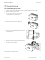
Dismantling the Inverter. . . . . . . . . . . . . . . . . . . . . . . . . . . . . . . 67
Packing the Inverter. . . . . . . . . . . . . . . . . . . . . . . . . . . . . . . . . . 68
Storing the Inverter . . . . . . . . . . . . . . . . . . . . . . . . . . . . . . . . . . 68
Disposing of the inverter . . . . . . . . . . . . . . . . . . . . . . . . . . . . . . 68
11
11.1
Technical Data . . . . . . . . . . . . . . . . . . . . . . . . . . . . . . . . . . 69
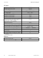
DC/AC . . . . . . . . . . . . . . . . . . . . . . . . . . . . . . . . . . . . . . . . . . . 69
11.1.1
Windy Boy 3300 . . . . . . . . . . . . . . . . . . . . . . . . . . . . . . . . . . . . . . . . . . . . . 69
11.1.2
Windy Boy 3800 . . . . . . . . . . . . . . . . . . . . . . . . . . . . . . . . . . . . . . . . . . . . . 71
11.2
11.3
11.4
11.5
11.6
11.7
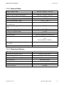
General data . . . . . . . . . . . . . . . . . . . . . . . . . . . . . . . . . . . . . . 73
Protective Devices . . . . . . . . . . . . . . . . . . . . . . . . . . . . . . . . . . . 73
Licences. . . . . . . . . . . . . . . . . . . . . . . . . . . . . . . . . . . . . . . . . . . 74
Climatic Conditions . . . . . . . . . . . . . . . . . . . . . . . . . . . . . . . . . . 74
Features . . . . . . . . . . . . . . . . . . . . . . . . . . . . . . . . . . . . . . . . . . 74
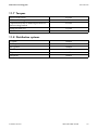
Torques . . . . . . . . . . . . . . . . . . . . . . . . . . . . . . . . . . . . . . . . . . . 75
11.8
Distribution systems . . . . . . . . . . . . . . . . . . . . . . . . . . . . . . . . . . 75
Installation Manual
WB33-38-IA-IEN120940
5
Table of Contents
SMA Solar Technology AG
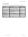
12
Accessories . . . . . . . . . . . . . . . . . . . . . . . . . . . . . . . . . . . . . 76
13
Contact . . . . . . . . . . . . . . . . . . . . . . . . . . . . . . . . . . . . . . . . 77
6
WB33-38-IA-IEN120940
Installation Manual
SMA Solar Technology AG
Information on this Manual
1 Information on this Manual
1.1 Validity
This manual describes the mounting, installation, commissioning, maintenance and troubleshooting
procedures for the following SMA inverters:
• Windy Boy 3300 (WB 3300, WB 3300-11, WB 3300-IT)
• Windy Boy 3800 (WB 3800, WB 3800-11, WB 3800-IT)
Please store this manual where it will be accessible at all times.
1.2 Target Audience
This manual is for the use of electrically skilled persons. The tasks described in this manual may be
performed by electrically skilled persons only.
1.3 Additional Information
You will find further information on special topics, such as the design of a miniature circuit-breaker or
the description of the operating parameters, in the download area at www.SMA.de/en.
Please refer to the user manual provided for detailed information on operating the inverter.
Installation Manual
WB33-38-IA-IEN120940
7
Information on this Manual
SMA Solar Technology AG
1.4 Symbols Used
The following types of safety precautions and general information are used in this manual:
DANGER!
DANGER indicates a hazardous situation which, if not avoided, will result in death or
serious injury.
WARNING!
WARNING indicates a hazardous situation which, if not avoided, could result in death or
serious injury.
CAUTION!
CAUTION indicates a hazardous situation which, if not avoided, could result in minor or
moderate injury.
NOTICE!
NOTICE indicates a situation which, if not avoided, could result in property damage.
Information
Information provides tips that are valuable for the optimal installation and operation of the
product.
☑
8
This symbol indicates the result of an action.
WB33-38-IA-IEN120940
Installation Manual
SMA Solar Technology AG
Safety
2 Safety
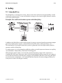
2.1 Intended Use
The Windy Boy is a wind power inverter, which converts the rectified current generated by a small
wind turbine system into AC current and feeds this energy into the electricity grid, domestic network
or the Sunny Island system.
Principle of a small wind turbine system with Windy Boy
In addition, the Windy Boy can be used as inverter for energy converters based on permanent magnet
generators (hydro-power systems, combined heat and power plants, diesel generators, etc.).
The manufacturer of the small wind turbine system or generator must have approved his plant for
operation with this Windy Boy.
For safety reasons, it is not permitted to modify the product or install components that are not explicitly
recommended or distributed by SMA Solar Technology AG.
When designing the PV plant, ensure that the permitted operating range of all components is
complied with at all times. Moreover, make sure that appropriate protective measures are in place to
ensure that the maximum permissible input voltage is not exceeded. SMA Solar Technology AG offers
you the necessary components, such as the Windy Boy Protection Box (overvoltage protection for
wind power inverters including the rectifier).
Installation Manual
WB33-38-IA-IEN120940
9
Safety
SMA Solar Technology AG
2.2 Safety Precautions
DANGER!
Electric shock due to high voltages in the inverter when connecting the device.
Death or serious injuries.
• All work on the inverter must be carried out by a trained electrically skilled person
only.
• Work on the inverter should only be carried out as described in this manual.
• All safety precautions listed here must be observed.
CAUTION!
Risk of burns through contact with the hot enclosure during operation. Burns to
the palm of the hand.
• Do not touch the inverter enclosure during operation.
Problems while performing the described activities
If you have problems while performing any of the activities described in this manual, please
contact SMA Solar Technology AG (see Section 13 "Contact" (page 77)).
10
WB33-38-IA-IEN120940
Installation Manual
SMA Solar Technology AG
Safety
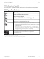
2.3 Explanation of Symbols
This section gives an explanation of all the symbols found on the inverter and on the type label.
2.3.1 Symbols on the Inverter
Symbol
Explanation
Operation display
Indicates the operating state of the inverter.
Earth fault or varistor defective
Read Section 9.3 "Red LED is Permanently On" (page 62).
Fault or disturbance.
Read Section 9 "Troubleshooting" (page 56).
You can operate the display by tapping the enclosure lid.
• Single tap: the backlight switches on or the display scrolls to the next
display message.
• Double tap in quick succession*: The inverter shows the display
messages from the start-up phase again (see Section 6.2 "Display
Messages During the Start-up Phase" (page 40)).
QR-Code®** for SMA bonus programme
You will find information on the SMA bonus programme at
www.SMA-Bonus.com.
* This function is valid as of firmware version 4.00.
** QR-Code is a registered trademark of DENSO WAVE INCORPORATED.
Installation Manual
WB33-38-IA-IEN120940
11
Safety
SMA Solar Technology AG
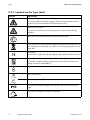
2.3.2 Symbols on the Type Label
Symbol
Explanation
Beware of dangerous electrical voltage.
The inverter operates at high voltages. All work on the inverter must be
carried out by a trained electrically skilled person only.
Beware of hot surface.
The inverter can become hot during operation. Avoid contact during
operation.
Observe all documentation that accompanies the inverter.
The inverter must not be disposed of together with the household waste. For
more information on disposal, see Section 10.4 "Disposing of the inverter"
(page 68).
CE marking
The inverter complies with the requirements of the applicable EC directives.
RAL quality mark for solar products
The inverter complies with the requirements of the German Institute for
Quality Assurance and Labelling.
The inverter has a transformer.
Direct current (DC)
Alternating current (AC)
The inverter is protected against dust intrusion and water jets from any
angle.
The inverter is suitable for outdoor installation.
12
WB33-38-IA-IEN120940
Installation Manual
SMA Solar Technology AG
Unpacking
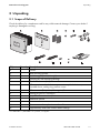
3 Unpacking
3.1 Scope of Delivery
Check the delivery for completeness and for any visible external damage. Contact your dealer if
anything is damaged or missing.
Object
A
B
C
D
E
F
Quantity
1
1
2
5
2
1
G
H
I
K
L
M
N
6
6
1
1
1
1
1
Description
Inverter
Wall mounting bracket
Ventilation grid (1 x left, 1 x right)
Filler-plug for wall mounting (sealing)
Cheese-head screw (M6)
AC connection socket: bush insert, protective cap for bush insert,
threaded sleeve, sealing ring, pressure screw
DC connectors (3 x positive, 3 x negative)*
Sealing plug for DC connectors
Jumper for communication / fan test
Installation manual
User manual
Document set with explanations and certificates
Supplementary sheet with inverter default settings
* For WB 3300-11 / WB 3800-11 2 ⨯ positive, 2 ⨯ negative
Installation Manual
WB33-38-IA-IEN120940
13
Unpacking
SMA Solar Technology AG
3.2 Identifying the Inverter
You can identify the inverter be means of the type label. The type label is located on the right-hand
side of the enclosure.
On the type label you will find the type (Type / Model) and the serial number (Serial No.) of the
inverter.
14
WB33-38-IA-IEN120940
Installation Manual
SMA Solar Technology AG
Assembly
4 Assembly
4.1 Safety
DANGER!
Danger to life due to fire or explosion
Despite careful construction, electrical devices can cause fires.
• Do not mount the inverter on flammable construction materials.
• Do not mount the inverter in areas where highly flammable materials are stored.
• Do not mount the inverter in a potentially explosive atmosphere.
CAUTION!
Risk of burns due to hot enclosure parts
• Do not touch the enclosure during operation.
CAUTION!
Risk of injury due to the heavy weight of the inverter.
• Bear in mind that the inverter weighs approx. 38 kg
Installation Manual
WB33-38-IA-IEN120940
15
Assembly
SMA Solar Technology AG
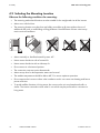
4.2 Selecting the Mounting Location
Observe the following conditions for mounting:
• The mounting method and location must be suitable for the weight and size of the inverter.
• Mount on a solid surface.
• The mounting location must be clear and safely accessible at all times without the use of
additional aids such as scaffolding or lifting platforms. Non-fulfillment of these criteria may
restrict service friendliness.
• Mount vertically or tilted backwards by max. 45°.
• Never mount the device with a forward tilt.
• Never mount the device with a sideways tilt.
• Do not mount in a horizontal position.
• The connection area must point downwards.
• Mount at eye level so that operation states can be read.
• The ambient temperature should be below 40°C to ensure optimum operation.
• Do not expose the inverter to direct solar irradiation as this can cause over-heating and hence
power reduction.
• To avoid audible vibrations in living areas, do not mount the unit on plasterboard walls or
similar. The inverter can make noises when in use which may be perceived as a nuisance in
living areas.
16
WB33-38-IA-IEN120940
Installation Manual
SMA Solar Technology AG
Assembly
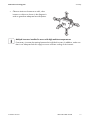
• Observe minimum clearances to walls, other
inverters or objects as shown in the diagram in
order to guarantee adequate heat dissipation.
Multiple inverters installed in areas with high ambient temperatures
If necessary, increase the spacing between the individual inverters. In addition, make sure
there is an adequate fresh-air supply to ensure sufficient cooling of the inverters.
Installation Manual
WB33-38-IA-IEN120940
17
Assembly
SMA Solar Technology AG
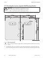
4.3 Mounting the Inverter using the Wall Mounting Bracket
CAUTION!
Risk of injury due to the heavy weight of the inverter.
• Bear in mind that the inverter weighs approx. 38 kg
1. Use the wall mounting bracket as a drilling template and mark the positions of the drill holes.
Mounting material
When mounting the wall mounting bracket, use fastening material suitable for the mounting
surface.
2. Use filler-plugs to fill any unused holes in the wall mounting bracket. Insert the filler-plugs into
the wall mounting bracket from the outside (the side that will later be placed against the wall).
18
WB33-38-IA-IEN120940
Installation Manual
SMA Solar Technology AG
Assembly
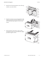
3. Attach the wall mounting bracket to the wall using
suitable screws and washers.
4. Hook the inverter by its top mounting plates into the
wall mounting bracket with both attachments of the
wall bracket passing through the cutouts on the
inverter.
5. Visual inspection: The inverter is only correctly
mounted when both rear panel attachments slightly
protrude through the cutouts.
Installation Manual
WB33-38-IA-IEN120940
19
Assembly
SMA Solar Technology AG
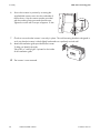
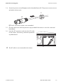
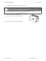
6. Secure the inverter in position by screwing the
supplied M6 contact screw into the underside of
the enclosure. Use the contact washer provided
with the toothing facing towards the enclosure.
Tighten the screw with a torque of approx. 5 Nm.
7. Check to ensure that the inverter is securely in place. The wall mounting bracket is designed in
such way that the inverter is tilted slightly backwards on a perfectly vertical wall.
8. Attach the ventilation grids provided to the inverter.
To help you identify the sides,
"links/left" or "rechts/right" is printed on the inside
of the ventilation grids.
☑ The inverter is now mounted.
20
WB33-38-IA-IEN120940
Installation Manual
SMA Solar Technology AG
Electrical Connection
5 Electrical Connection
5.1 Safety
NOTICE!
Electrostatic discharge can damage the inverter
Internal components of the inverter can be irreparably damaged by electrostatic
discharge.
• Earth yourself before touching a component.
5.2 Overview of the Connection Area
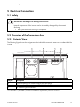
5.2.1 Exterior View
The following figure shows the assignment of the individual connection areas on the underside of the
inverter.
Object
A
B
C
Description
Enclosure openings for communication (with filler-plugs)
DC connectors for connecting the DC cables*
AC socket for grid connection
* For WB 3300-11 / WB 3800-11, the inverter is fitted with 2 negative and 2 positive DC connectors.
Installation Manual
WB33-38-IA-IEN120940
21
Electrical Connection
SMA Solar Technology AG
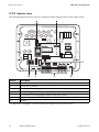
5.2.2 Interior view
The following figure shows the various components and connection areas of the open inverter.
Object
A
B
C
D
E
F
G
Description
Slot and connection area for communication
Jumper slot for fan test
Flat male tab for earthing the cable shield with cable-bound communication
AC socket for grid connection
DC connector for connecting the small wind turbine system*
Enclosure opening with filler-plugs for communication
Varistors
* For WB 3300-11 / WB 3800-11, the inverter is fitted with 2 negative and 2 positive DC connectors.
22
WB33-38-IA-IEN120940
Installation Manual
SMA Solar Technology AG
Electrical Connection
5.3 Connection to the Electricity Grid (AC)
5.3.1 Conditions for AC Connection
Connection requirements of the network operator
Always comply with the connection requirements of your network operator.
Cable sizing
Use Sunny Design Version 2.0 or higher for sizing the conductor cross-sections
(see Sunny Design program at www.SMA.de/en).
The maximum cable lengths as a function of conductor cross-section are shown in the following table.
Cable cross-section
4 mm²
Maximum cable length
WB 3300 / WB 3300-11 / WB 3800 / WB 3800-11 /
WB 3300-IT
WB 3800-IT
18.5 m
16 m
Cable requirements
Object
A
B
C
Installation Manual
Description
External diameter
Conductor cross-section
Stripping length
Value
6 mm … 14 mm
4 mm²
8 mm
WB33-38-IA-IEN120940
23
Electrical Connection
SMA Solar Technology AG
Load disconnect unit
You must install a separate miniature circuit-breaker for each inverter in order to ensure that the
inverter can be securely disconnected under load. The maximum permissible fuse protection can be
found in Section 11 "Technical Data" (page 69).
Detailed information and examples on the design of miniature circuit-breakers are available in the
Technical Information "Miniature circuit-breakers" to be found in the download area of
SMA Solar Technology AG at www.SMA.de/en.
DANGER!
Danger to life by fire.
When more than 1 inverter is connected in parallel to the same miniature circuit-breaker,
the protective function of the miniature circuit-breaker is no longer guaranteed. It can result
in a cable fire or destruction of the inverter.
• Never connect several inverters to the same miniature circuit-breaker.
• Observe the maximum permissible fuse protection of the inverter when selecting the
miniature circuit-breaker.
DANGER!
Danger to life by fire.
When a generator (inverter) and a load are connected to the same miniature circuitbreaker, the protective function of the miniature circuit-breaker is no longer guaranteed.
The currents from the inverter and the grid can accumulate to form overcurrents that are not
detected by the miniature circuit-breaker.
• Never connect the load between the
inverter and the miniature circuit-breaker
without protection.
• Always protect the load separately.
NOTICE!
Damage to the inverter due to use of screw-type fuses as load disconnection units
A screw-type fuse, e.g. DIAZED fuse or NEOZED fuse, is not a switch-disconnector and thus
may not be used as a load disconnection unit. A screw-type fuse only acts as cable
protection.
Disconnection under load using a screw-type fuse may damage the inverter.
• Use only a switch-disconnector or a miniature circuit-breaker as a load disconnection
unit.
24
WB33-38-IA-IEN120940
Installation Manual
SMA Solar Technology AG
Electrical Connection
5.3.2 Connecting the Inverter to the Electricity Grid (AC)
Overview of the AC connection socket
Object
A
B
C
D
E
Description
Protective cap for bush insert
Bush insert
Threaded sleeve with sealing ring for cable diameters from 10 mm … 14 mm
Sealing ring for cable cross-section from 6 mm … 10 mm
Pressure screw
Procedure
1. Check that the line voltage is within the permissible voltage range.
The exact operating range of the inverter is specified in the operating parameters. The relevant
document can be found in the download area at www.SMA.de/en, in the "Technical
Description" category of the respective inverter.
2. Disconnect the miniature circuit-breaker and secure against accidental or inadvertent
reconnection.
3. If necessary, replace the sealing ring of the threaded sleeve with the sealing ring provided.
– Pull the sealing ring out of the threaded sleeve.
– Insert the smaller sealing ring.
4. Pass the pressure screw (E) over the AC cable.
Installation Manual
WB33-38-IA-IEN120940
25
Electrical Connection
SMA Solar Technology AG
5. Pass the threaded sleeve (C) with the sealing ring over the AC cable.
6. Bend the AC cable The bending radius must be at
least four times the cable diameter.
7. Shorten the cable.
8. Shorten phase L and neutral conductor
N 4 to 5 mm.
9. Insert the PE conductor (green-yellow) into the
screw terminal with the earth sign on the bush insert
and tighten the screw. The PE conductor must be
longer than the connection wires N and L.
10. Insert neutral conductor N (blue) into screw
terminal N on the bush insert and tighten the screw.
11. Insert phase L (brown or black) into screw terminal
L on the bush insert and tighten the screw.
12. Check that the connection wires are securely
connected.
13. Push the threaded sleeve (C) onto the bush insert
(B) until it audibly snaps into place.
26
WB33-38-IA-IEN120940
Installation Manual
SMA Solar Technology AG
Electrical Connection
14. Screw the pressure screw (E) tightly onto the threaded sleeve (C). The pressure screw acts as a
seal and to relieve strain.
☑ The AC connection socket is now assembled.
15. Close the bush insert with the protective cap provided if the inverter is not to be connected
immediately.
16. Insert the AC connection socket into the AC socket
on the inverter. If necessary, remove the protective
cap beforehand.
☑ The AC cable is now connected to the inverter.
Installation Manual
WB33-38-IA-IEN120940
27
Electrical Connection
SMA Solar Technology AG
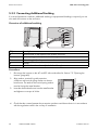
5.3.3 Connecting Additional Earthing
If a second protective conductor, additional earthing or equipotential bonding is required, you can
also earth the inverter on the enclosure.
Overview of additional earthing
Object
A
B
C
D
E
Description
Metal bracket on the bottom of the inverter enclosure
Conical spring washer (included in delivery)
Terminal lug (M6) with protective conductor
Washer
M6x12 cheese-head screw (included in delivery)
Procedure
1. Disconnect the inverter on the AC and DC side as described in Section 7.2 "Opening the
Inverter" (page 48).
2. Align washer, terminal lug with protective
conductor and conical spring washer on cheesehead screw. The teeth of the conical spring washer
must be facing the metal bracket.
3. Insert the cheese-head screw into the metal bracket
and tighten to a torque of 6 Nm.
4. Check that the contact between the protective conductor and the enclosure is in accordance
with the regulations valid in the country of installation.
28
WB33-38-IA-IEN120940
Installation Manual
SMA Solar Technology AG
Electrical Connection
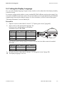
5.4 Setting the Display Language
You can set the display language using the rotary switches on the underside of the display assembly
inside the inverter.
For inverters configured to the Italian country standard DK 5940, different switch positions apply. You
can see the standard to which the inverter was set upon delivery on the type label and on the included
supplementary sheet with the default settings. For more information, see the Technical Description
"Operating Parameters" at www.SMA.de/en.
Procedure
1. Open the inverter as described in Section 7.2 "Opening the Inverter" (page 48).
2. Set the switch to the appropriate language. The
following switch settings apply to all national
standards except for DK 5940:
Language
German
English
French
Spanish
Rotary switch S2
B
B
A
A
Rotary switch S1
B
A
B
A
The following switch settings apply to inverters that are set to the Italian national standard
DK 5940:
Language Rotary switch S2 Rotary switch S1
Italian
B
A
English
A
A
3. Close the inverter as described in Section 7.3 "Closing the Inverter" (page 50).
☑ The display language is now set.
Installation Manual
WB33-38-IA-IEN120940
29
Electrical Connection
SMA Solar Technology AG
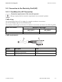
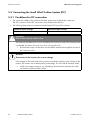
5.5 Connecting the Small Wind Turbine System (DC)
5.5.1 Conditions for DC connection
• The connection cables of the small wind turbine system must be fitted with connectors.
The DC connectors for the DC connection are included in the delivery.
• The following limit values must not be exceeded at the DC input of the inverter:
Maximum input voltage
500 V
Maximum input current
20 A
DANGER!
Risk of lethal electric shock or fire
The maximum possible input current is limited by the connectors used. If the connectors are
overloaded, an electric arc may occur, thus causing a fire risk.
• Ensure that the input current does not exceed the maximum through-fault current of
the connectors used.
NOTICE!
Destruction of the inverter due to overvoltage
If the voltage of the small wind turbine system exceeds the maximum input voltage of the
inverter, the inverter can be destroyed by overvoltage. This will void all warranty claims.
• Install overvoltage protection, e.g. Windy Boy Protection Box, between the small
wind turbine system and the inverter.
30
WB33-38-IA-IEN120940
Installation Manual
SMA Solar Technology AG
Electrical Connection
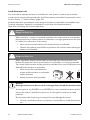
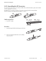
5.5.2 Assembling the DC Connectors
For connection to the inverter, all connection cables of the small wind turbine system must be fitted
with the supplied DC connectors.
Assemble the DC connectors as follows. Ensure the connectors have the correct polarity.
The DC connectors are marked with the symbols "+" and " − ".
Cable requirements
• Use a PV1-F cable.
Procedure
1. Insert the stripped cable into the plug up to the stop.
2. Press the clamping bracket down until it audibly
snaps into place.
Installation Manual
WB33-38-IA-IEN120940
31
Electrical Connection
SMA Solar Technology AG
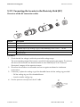
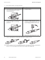
3. Ensure that the cable is correctly positioned:
Result
What to do
☑ If the stranded wire is visible in the chamber • Proceed to step 4.
of the clamping bracket, the cable is
correctly positioned.
☑ If the stranded wire is not visible in the
chamber, the cable is not correctly
positioned.
• Release the clamping bracket. Do this by
inserting a screwdriver (blade width: 3.5 mm)
into the clamping bracket to lever it open.
• Remove the cable and go back to step 1.
4. Push the cable gland up to the thread and fasten to a torque of 2 Nm.
☑ The DC connectors are now assembled and can be connected to the inverter as described in
Section 5.5.4 "Connecting the Small Wind Turbine System (DC)" (page 34).
32
WB33-38-IA-IEN120940
Installation Manual
SMA Solar Technology AG
Electrical Connection
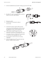
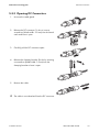
5.5.3 Opening DC Connectors
1. Unscrew the cable gland.
2. Release the DC connector. To do so, insert a
screwdriver (blade width: 3.5 mm) into the lateral
catch and lever it open.
3. Carefully pull the DC connector apart.
4. Release the clamping bracket. Do this by inserting
a screwdriver (blade width: 3.5 mm) into the
clamping bracket to lever it open.
5. Remove the cable.
☑ The cable is now detached from the DC connector.
Installation Manual
WB33-38-IA-IEN120940
33
Electrical Connection
SMA Solar Technology AG
5.5.4 Connecting the Small Wind Turbine System (DC)
DANGER!
Danger to life due to high voltages in the inverter
• Before connecting the small wind turbine system, ensure that it is not running.
1. Connect the assembled DC connectors to the inverter.
☑ The DC connectors click audibly into position.
To release the DC connectors, see Section 7.2 "Opening the Inverter" (page 48).
34
WB33-38-IA-IEN120940
Installation Manual
SMA Solar Technology AG
Electrical Connection
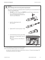
NOTICE!
Risk of damage to the inverter by moisture penetration
The inverter is only properly sealed when all the unused DC inputs are closed with DC plug
connectors and sealing plugs:
• DO NOT insert the sealing plugs DIRECTLY into the DC inputs on the inverter.
• For unused DC plug connectors, push
down the clamping bracket and push the
swivel nut up to the thread.
1
2
+
• Insert the sealing plug into the
DC connector.
+
• Tighten the DC connector (torque: 2 Nm).
+
• Insert the DC plug connectors with sealing
plugs into the corresponding DC inputs on
the inverter.
☑ The DC connectors click audibly into
position.
2. Ensure that all DC connectors are securely in place.
☑ The small wind turbine system is now connected.
You can now commission the inverter as described in Section 6 "Commissioning" (page 39).
The following connections are optional.
Installation Manual
WB33-38-IA-IEN120940
35
Electrical Connection
SMA Solar Technology AG
5.6 Communication
The inverter is equipped with a slot for communication interfaces which enable it to communicate with
data loggers (e.g., Sunny WebBox) or a PC with appropriate software (e.g., Sunny Explorer).
Refer to the communication interface manual for a detailed wiring diagram and installation
instructions.
The inverter's active power can be limited or the displacement power factor cos φ can be set
externally using the Power Reducer Box by SMA Solar Technology AG. You will find detailed
information on active power limitation and on setting the displacement power factor cos φ in the
technical description "Operating Parameters" at www.SMA.de/en.
5.7 Setting the Grid and Country Parameters
Changing grid-relevant parameters and country parameters
To change grid-relevant parameters, you need a personal access code – the so-called
SMA Grid Guard code. The application form for the personal access code is available in
the download area at www.SMA.de/en, in the "Certificate" category of the respective
inverter.
Confirm the changes to these parameters with your network operator.
A detailed description of the operating parameters for the inverter is available in the download area
at www.SMA.de/en in the category "Technical Description" of the respective inverter.
5.7.1 Setting the Installation Country
Using the "Default" parameter, you can set the country of installation and/or the grid connection
standard valid for that country via a communication product (e.g., Sunny WebBox) or a PC with
corresponding software (e.g., Sunny Data Control or Sunny Explorer). However, this is only required
if the inverter was originally ordered for another country. You can see the standard to which the
inverter was set upon delivery on the type label and on the included supplementary sheet with the
default settings.
36
WB33-38-IA-IEN120940
Installation Manual
SMA Solar Technology AG
Electrical Connection
5.7.2 Setting to Stand-alone Grid Operation
To operate the inverter in an stand-alone system with Sunny Island, you must set the inverter via the
"Default" parameter to stand-alone grid operation ("OFF-Grid").
There are several ways of setting the inverter to stand-alone grid operation:
• Setting via Sunny WebBox
or
• Setting via Sunny Data Control or Sunny Explorer
DANGER!
Danger to life due to high voltages in the event of electricity grid failure
If you set the inverter to stand-alone grid operation, it does not fulfil any country-specific
standards or guidelines. If grid failure occurs, there will consequently be a danger of
backfeed.
• Never operate the inverter directly on the electricity grid when set to stand-alone grid
operation.
Installation Manual
WB33-38-IA-IEN120940
37
Electrical Connection
SMA Solar Technology AG
5.8 Polynomial Curve
The polynomial curve is a programmable power curve which is dependent on the DC input voltage.
By adapting the default polynomial curve to the small wind turbine system being used, you can
optimise the energy output of the system.
To adapt the polynomial curve of the inverter to the wind turbine system being used, you can change
the following parameters on the PC with the "Windy Boy Setup Tool" (www.SMA.de/en):
• Vpv-Start
• UdcWindStart
• Wind_a0 ... Wind_a3
• Pmax
• P-Wind-Ramp
• KP-Wind-Reg
• KI-Wind-Reg
• T-Stop
A description of the operating parameters is available in the download area at www.SMA.de/en in
the category "Technical Description" of the respective inverter.
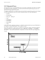
The inverter regulates its output power according to the generator voltage. The following diagram
shows the function of a typical polynomial curve in a WB 3300 / WB 3300-11 / WB 3800 /
WB 3800-11. Here, the AC power fed in is depicted as a function of the DC input voltage of the
inverter.
38
WB33-38-IA-IEN120940
Installation Manual
SMA Solar Technology AG
Commissioning
6 Commissioning
6.1 Commissioning the Inverter
1. Check the following requirements before commissioning:
– Correct mounting and connection of the inverter.
– Appropriately sized miniature circuit-breaker.
– Correct earthing of the small wind turbine system in accordance with the instructions of the
manufacturer.
– The rectifier and overvoltage protection (e.g. Windy Boy Protection Box) are installed
between the small wind turbine system and the inverter.
– Unused DC inputs are closed with the corresponding DC connectors and sealing plugs
2. Switch on the miniature circuit-breaker.
3. Commission the small wind turbine system in accordance with the instructions of the
manufacturer.
☑ All 3 LEDs on or flashing: the start-up phase commences.
☑ Green LED on: commissioning successful.
or
☑ Green LED flashing: grid connection conditions have not yet been reached. Wait until the
green LED is permanently on.
or
☑ The red or yellow LED lights up or flashes: a disturbance has occurred. Proceed to step 3.
Object
A
B
C
Description
Green LED: operation
Red LED: earth fault or varistor
defective
Yellow LED: disturbance
Self-test in accordance with DK 5940, Ed. 2.2 during initial start-up
(applies to Italy only)
The Italian DK 5940 standard prescribes that an inverter can only operate on the electricity
grid if the disconnection times for overvoltage, undervoltage, minimum frequency and
maximum frequency have been checked.
Start the self-test as described in Section 6.3 "Self-Test in Accordance with DK 5940, Ed.
2.2 (Applies to Italy Only)" (page 41). The test takes approx. 8 minutes.
4. Read Section 9 "Troubleshooting" (page 56) and if necessary eliminate the fault or disturbance.
Installation Manual
WB33-38-IA-IEN120940
39
Commissioning
SMA Solar Technology AG
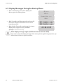
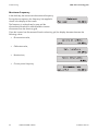
6.2 Display Messages During the Start-up Phase
• After commissioning, the inverter displays the
device type in the start-up phase.
SB xxx
WRxxx
Sunny Boy xxx
WRxx
• After 5 seconds or a further tap on the enclosure lid,
the inverter displays the firmware version of the
internal processors.
• After a further 5 seconds or another tap, the inverter
displays the configured country standard
(example: "VDE-AR-N4105").
Show display messages again (valid from Firmware Version 4.00)
If you want to view the display messages of the start-up phase again during operation, tap
the enclosure lid twice in quick succession.
40
WB33-38-IA-IEN120940
Installation Manual
SMA Solar Technology AG
Commissioning
6.3 Self-Test in Accordance with DK 5940, Ed. 2.2
(Applies to Italy Only)
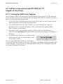
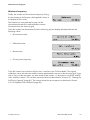
6.3.1 Starting the Self-Test by Tapping
You can start the check of the disconnection times by tapping on the enclosure lid. The prerequisite
for this is that the inverter country setting has been set to Italy (IT/DK5940) or "trimmed". Proceed as
follows for checking the disconnection times:
1. Connect the small wind turbine system to the inverter. The inverter can only initialise once the
small wind turbine system is producing enough power.
2. Connect the inverter on the AC side. To do this, you have to make the AC connection
(AC plug or direct connection) and switch on the circuit-breaker of the grid feed cable
(fuse or miniature circuit-breaker).
3. The inverter is now in the initialisation phase, i.e. all three LEDs are simultaneously on.
Start the self-test immediately after all three LEDs have gone out by tapping on the display of
the inverter.
4. The display queries whether you would like to start
the test sequence. Tap on the display again within
30 seconds to confirm.
Once you have started the test sequence, the inverter
successively checks the disconnection times for overvoltage, undervoltage, maximum frequency and
minimum frequency. During the tests, the values described in Section 6.3.2 "Completion of the Selftest" (page 42) appear in the display.
Installation Manual
WB33-38-IA-IEN120940
41
Commissioning
SMA Solar Technology AG
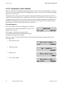
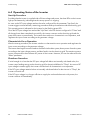
6.3.2 Completion of the Self-test
Note the values which are displayed during the self-test. These values must be entered in a test report.
The test results of the individual tests are displayed three times in succession. Each display message
appears for 10 seconds.
During the self-test, the upper and lower disconnection thresholds for each protective function are
subject to linear adjustment with a modification of 0.05 Hz/s and 0.05 Vn/s for the frequency and
voltage monitoring. As soon as the actual measured value exceeds the permitted range (adjusted
disconnection threshold), the inverter disconnects from the electricity grid. In this way, the inverter
determines the reaction time and the self-test is performed.
Overvoltage test
The inverter begins with the overvoltage test. During the
test sequence, the voltage limit applied is shown in the
display of the inverter.
The voltage is reduced step by step until the
disconnection threshold is reached and the inverter
disconnects from the electricity grid.
Once the inverter has disconnected from the electricity grid, the display alternates between the
following values:
• Disconnection value,
• Calibration value,
• Reaction time,
• Current line voltage.
42
WB33-38-IA-IEN120940
Installation Manual
SMA Solar Technology AG
Commissioning
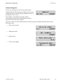
Undervoltage test
After the overvoltage test, the inverter performs the
undervoltage test. During the test sequence, the current
calibration value of the voltage limit applied is shown in
the display of the inverter.
The voltage is increased step by step until the
disconnection threshold is reached and the inverter
disconnects from the electricity grid.
Once the inverter has disconnected from the electricity grid, the display alternates between the
following values:
• Disconnection value,
• Calibration value,
• Reaction time,
• Current line voltage.
Installation Manual
WB33-38-IA-IEN120940
43
Commissioning
SMA Solar Technology AG
Maximum frequency
In the third step, the inverter tests the maximum frequency.
During the test sequence, the frequency limit applied is
shown in the display of the inverter.
The frequency is reduced step by step until the
disconnection threshold is reached and the inverter
disconnects from the electricity grid.
Once the inverter has disconnected from the electricity grid, the display alternates between the
following values:
• Disconnection value,
• Calibration value,
• Reaction time,
• Current power frequency.
44
WB33-38-IA-IEN120940
Installation Manual
SMA Solar Technology AG
Commissioning
Minimum frequency
Finally, the inverter tests the minimum frequency. During
the test sequence, the frequency limit applied is shown in
the display of the inverter.
The frequency is increased step by step until the
disconnection threshold is reached and the inverter
disconnects from the electricity grid.
Once the inverter has disconnected from the electricity grid, the display alternates between the
following values:
• Disconnection value,
• Calibration value,
• Reaction time,
• Current power frequency.
Once the inverter has carried out all four tests, it switches to the "Turbine Mode". The original
calibration values are then reset and the inverter automatically connects to the electricity grid. If you
wish to carry out the test again, you must switch off the inverter, i.e. disconnect it on the AC and DC
sides, and then restart it. You can then restart the self-test as described in Section 6.3.1 "Starting the
Self-Test by Tapping" (page 41). The inverter restarts the test sequence as described in Section
6.3.2 "Completion of the Self-test" (page 42).
Installation Manual
WB33-38-IA-IEN120940
45
Commissioning
SMA Solar Technology AG
6.4 Operating States of the Inverter
Start-Up Procedure
Providing that the inverter is supplied with sufficient voltage and power, the three LEDs on the inverter
light up simultaneously, indicating that the start-up process is ongoing.
As soon as the DC input voltage reaches the value configured for the parameter "Vpv-Start", the
inverter triggers several self-tests, measuring procedures and synchronization with the electricity grid.
This operating state is indicated on the inverter by the flashing green LED.
Once the DC input voltage has reached the "Vpv-Start" value for the time configured in "T-Start" and
all the tests have been completed successfully, the inverter connects to the electricity grid and the
green LED comes on permanently. The inverter then switches to characteristic-curve operation, and
regulates the input current according to the generator voltage.
Characteristic-Curve Operation
After the start-up procedure, the inverter switches to characteristic-curve operation and regulates the
input current according to the generator voltage.
The inverter then begins to exert a load on the small wind turbine system, draws power from the system
according to the input voltage present, and then feeds it into the electricity grid. The maximum power
output corresponds to the maximum AC power of the inverter. However, this can be reduced via the
"Pmax" parameter.
Shutdown Procedure
If wind strength is so low that the DC input voltage falls below an internally calculated value, the
inverter stops feeding energy to the electricity grid for the period defined in "T-Stop". As soon as DC
input voltage increases again, the inverter switches back to characteristic-curve operation.
If the DC input voltage remains below an internally calculated value for the time set in "T-Stop", the
inverter will switch off.
If the DC input voltage is no longer sufficient to supply the on-board electronics with power, the
inverter switches off immediately.
46
WB33-38-IA-IEN120940
Installation Manual
SMA Solar Technology AG
Opening and Closing
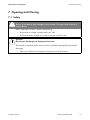
7 Opening and Closing
7.1 Safety
DANGER!
Electric shock due to high voltages in the inverter. This can result in death or
serious burns.
Before opening the inverter, observe the following:
• Ensure that no voltage is present on the AC side.
• Ensure that neither voltage nor current is present on the DC side.
NOTICE!
Electrostatic discharge can damage the inverter
The internal components of the inverter can be irreparably damaged by electrostatic
discharge.
• Earth yourself before touching any components inside the inverter.
Installation Manual
WB33-38-IA-IEN120940
47
Opening and Closing
SMA Solar Technology AG
7.2 Opening the Inverter
1. Stop the small wind turbine system and secure against restarting.
2. Disconnect the miniature circuit-breaker and secure against accidental or inadvertent
reconnection.
3. Use a current probe to make sure that no current is
present in the DC cables.
☑ If current is present, check the installation.
4. Release and disconnect all DC connectors. To do
this, insert a flat-blade screwdriver (blade width:
3.5 mm) into one of the side slots and pull the DC
plug connectors straight out. Take care
NOT TO PULL ON THE CABLE.
☑ All DC connectors are now disconnected from the inverter. The inverter is completely
disconnected from the small wind turbine system.
5. Ensure that no voltage is present at the DC connectors on the inverter.
☑ If voltage is present, check the installation.
6. Pull out the AC plug.
48
WB33-38-IA-IEN120940
Installation Manual
SMA Solar Technology AG
Opening and Closing
7. Check whether all LEDs and the display have gone out.
DANGER!
Danger to life due to high voltages in the inverter
The capacitors in the inverter take 15 minutes to discharge.
• Wait 15 minutes before opening the inverter.
8. Loosen the screws of the enclosure lid.
9. Slowly pull the enclosure lid forward and off.
☑ The inverter is now open and de-energised.
Installation Manual
WB33-38-IA-IEN120940
49
Opening and Closing
SMA Solar Technology AG
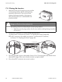
7.3 Closing the Inverter
1. Attach the enclosure lid using the 4 screws and the
conical spring washers with the toothing facing
toward the enclosure lid. The screws must be
tightened with approximately 6 Nm torque to
ensure that the enclosure is sealed and the lid
properly earthed.
DANGER!
Danger to life due to live enclosure lid
The earthing of the lid is effected by the conical spring washers.
• Attach the conical spring washers for all screws with the toothing facing toward the
enclosure lid.
2. Check the DC connectors for correct polarity and plug them in.
To release the DC connectors see Section 7.2 "Opening the Inverter" (page 48).
☑ The DC connectors click audibly into position. To release the DC connectors,
see Section 7.2 "Opening the Inverter" (page 48).
3. Close all unused DC inputs as described in Section 5.5.4 "Connecting the Small Wind Turbine
System (DC)" (page 34) to ensure that the inverter is properly sealed.
4. Ensure that all DC connectors are securely in place.
50
WB33-38-IA-IEN120940
Installation Manual
SMA Solar Technology AG
Opening and Closing
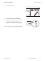
5. Connect the AC plug.
6. Switch on the miniature circuit-breaker.
7. Check whether the inverter display and LEDs
indicate a normal operating state
(see Section 6 "Commissioning" (page 39)).
☑ The inverter is now closed and in operation.
Installation Manual
WB33-38-IA-IEN120940
51
Maintenance and cleaning
SMA Solar Technology AG
8 Maintenance and cleaning
8.1 Cleaning the Inverter
NOTICE!
Damage to the display by use of cleaning agents
• If the inverter is dirty, clean the enclosure lid, the display and the LEDs with clear
water and a cloth only.
8.2 Checking Heat Dissipation
You only need to check the heat dissipation of the inverter if a visual inspection reveals a marked
clogging of the fan guard or the inverter frequently goes into the "Derating" operating state. The
ambient temperature and cooling efficiency determines whether the inverter switches to "Derating".
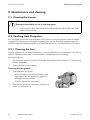
8.2.1 Cleaning the Fans
If the fan guard is only covered in loose dust, it can be cleaned with a vacuum cleaner. If you do not
achieve satisfactory results with a vacuum cleaner, dismantle the fans for cleaning.
Proceed as follows:
1. Disconnect the inverter on both the DC and AC sides as described in Section 7.2 "Opening the
Inverter" (page 48).
2. Wait for the fan to stop rotating.
Cleaning the fan guards
3. To dismantle the fan guard:
– Use a screwdriver to press both latches at the
right edge of the fan guard to the right and
dislodge it from the retainer.
– Carefully remove the fan guard.
4. Clean the fan guard with a soft brush, a paint brush,
a cloth or compressed air.
52
WB33-38-IA-IEN120940
Installation Manual
SMA Solar Technology AG
Maintenance and cleaning
Cleaning the Fans
5. Press the two upper latches towards the rear and
the lower latch towards the front.
6. Remove the fan by pulling it slowly and carefully
downwards.
7. Release and pull out the fan plug inside the inverter.
The fan cables are long enough to let you lift the fan out sufficiently to disconnect the internal
plugs in the inverter.
8. Remove the fan.
9. Clean the fan with a soft brush, a paint brush, or a damp cloth.
NOTICE!
Damage to the fan through use of compressed air
• Do not use compressed air to clean the fan. The fan could be damaged as a result.
10. After cleaning, reassemble everything in reverse order.
11. Check fan operation, as described in the following section.
8.2.2 Checking the Fans
There are two ways to check whether the fan is working:
• Set the "Fan Test" parameter to "1" in the installer mode using Sunny Data Control,
Sunny Explorer or Sunny WebBox.
or
• Plug the provided jumper into the system control board.
Setting Parameters
1. Request an installer password from the SMA Service Line (contact see page 77).
2. Set the "Fan Test" parameter to "1" in the installer mode.
3. Check the air-flow of the fan.
The inverter draws air in from underneath and blows it out at the top left. Listen for any unusual
noise that could indicate incorrect installation or that the fan is defective.
4. After checking the fan, set the "Fan Test" parameter back to "0".
☑ The fan test is now completed.
Installation Manual
WB33-38-IA-IEN120940
53
Maintenance and cleaning
SMA Solar Technology AG
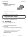
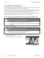
Plugging the Jumper
The inverter recognizes the jumper only after a system restart (i.e. all LEDs must have gone out prior
to restart).
1. Open the inverter as described in Section 7.2 "Opening the Inverter" (page 48).
2. Plug the provided jumper in the slot on the system control board as shown below.
3. Close the inverter as described in Section 7.3 "Closing the Inverter" (page 50).
4. Restart the inverter.
5. Check the air-flow of the fan.
The inverter draws air in from underneath and blows it out at the top left. Listen for any unusual
noise that could indicate incorrect installation or that the fan is defective.
6. Remove the jumper. Open and close the inverter as described in Section 7 "Opening and
Closing" (page 47).
☑ The fan test is now completed.
54
WB33-38-IA-IEN120940
Installation Manual
SMA Solar Technology AG
Maintenance and cleaning
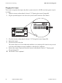
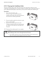
8.2.3 Cleaning the Ventilation Grids
There are ventilation grids on each side of the inverter. The inverter takes cooling air in from
underneath via the fan and blows it out again through the ventilation grids on the upper left side. To
ensure adequate heat dissipation of the inverter, you only need to clean the left ventilation grid.
Procedure
1. Remove the left ventilation grid.
Insert your finger in the space between the
ventilation grid and the upper part of the enclosure
and remove the ventilation grid laterally.
2. Clean the ventilation grid with a soft brush, a paint
brush or compressed air.
3. Re-attach the ventilation grid to the inverter.
To help you identify the sides, the ventilation grids
are marked on the inside with "rechts/right" and
"links/left".
☑ Cleaning of the ventilation grids is now complete.
NOTICE!
Risk of damage to the inverter through intrusion of insects.
• The ventilation grids must not be removed permanently, because otherwise the
device will not be protected against the intrusion of insects.
Installation Manual
WB33-38-IA-IEN120940
55
Troubleshooting
SMA Solar Technology AG
9 Troubleshooting
If the inverter displays blink codes which differ from those described below, contact the
SMA Service Line.
You will find a description of display messages during operation, status messages and measurement
channels in the user manual provided.
Do not try to carry out any repairs other than those described here. Instead, use
SMA Solar Technology AG's 24-hour replacement service (the inverter will be ready for dispatch at
the freight forwarder within 24 hours) and repair service.
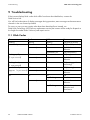
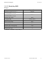
9.1 Blink Codes
Green
flashing
permanently on
Red
flashing
off
permanently on
Yellow
flashing
off
off
flashing rapidly
(3 x per second)
off
permanently on
permanently on
off
off
flashing slowly
off
off
(1 x per second)
goes off briefly
off
(approx. 1 x per second) permanently on
off
off
off
off
on / flashing
off
off
permanently on
on / flashing
56
WB33-38-IA-IEN120940
Status
OK (start-up phase)
OK (feed-in operation)
Earth fault or varistor
defective
OK (initialisation)
OK (stop)
Earth fault or varistor
defective
OK (waiting, grid
monitoring)
OK (derating)
Earth fault or varistor
defective
OK
Disturbance
Earth fault or varistor
defective
Earth fault or varistor
defective and
disturbance
Installation Manual
SMA Solar Technology AG
Troubleshooting
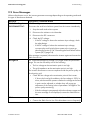
9.2 Error Messages
When a disturbance occurs, the inverter generates a message depending on the operating mode and
the type of disturbance detected.
Message
!PV-Overvoltage!
Description / Remedial Action
DC Overvoltage
!DISCONNECT DC!
Disconnect the small wind turbine system from the inverter immediately.
1. Stop the small wind turbine system.
2. Disconnect the miniature circuit-breaker.
3. Disconnect the DC connectors.
4. Check the DC voltage:
– If the DC voltage is above the maximum input voltage, check
the plant design.
– If the DC voltage is below the maximum input voltage,
reconnect the small wind turbine system to the inverter as
described in Section 5.5.4 "Connecting the Small Wind Turbine
System (DC)" (page 34).
ACVtgRPro
If the message is repeated, disconnect the inverter again and contact the
SMA Service Line.
The 10-minute-average line voltage is no longer within the permissible
range. This can be caused by one of the following:
• The line voltage at the termination point is too high.
• The grid impedance at the termination point is too high.
The inverter disconnects to assure compliance with the power quality of
the electricity grid.
• Check the line voltage at the termination point of the inverter:
– If, due to the local grid conditions, the line voltage is 253 V or
more, ask the network operator whether the voltage at the feedin point can be adjusted, or whether they will accept an
adjustment of the limiting value of parameter "ACVtgRPro" for
power quality monitoring.
Bfr-Srr
– If the line voltage is permanently within the tolerance range and
this error message is still displayed, contact the SMA Service
Line.
Internal measurement comparison fault or hardware defect.
• Contact the SMA Service Line if this disturbance occurs frequently.
Installation Manual
WB33-38-IA-IEN120940
57
Troubleshooting
SMA Solar Technology AG
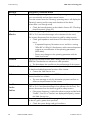
Message
Derating
Description / Remedial Action
The "Derating" operating state is a normal operating state which may
occur occasionally and can have several causes.
Once the inverter enters the "Derating" operating state, it will display the
"Derating" warning until the next total shutdown of the device
(when there is not enough wind).
• Check the heat dissipation as described in Section 8.2 "Checking
Heat Dissipation" (page 52).
Sudden changes in grid impedance are outside the permissible range
("Bfr" or "Srr" are internal messages of no relevance for the user).
dZac-Bfr
dZac-Srr
The inverter disconnects from the electricity grid for safety reasons.
• Check grid impedance and observe how often major deviations
occur.
– If repeated frequency fluctuations occur and this is causing
"dZac-Bfr" or "dZac-Srr" disturbances, ask the network operator
to agree to a modification of the operating parameters
(dZac-Max).
– Discuss any changes to the operating parameter with the
SMA Service Line.
Transitional disturbance while data is being written to or read from
EEPROM. The data has no relevance to safe operation.
EEPROM
EEPROM dBh
• This disturbance has no effect on the performance of the inverter.
EEPROM data is defective, the inverter has switched off because the loss
of data has disabled important functions of the inverter.
EeRestore
• Contact the SMA Service Line.
One of the duplicate records in the EEPROM is defective and has been
restored without loss of data.
Fac-Bfr
• This error message is only for information purposes and has no
effect on the performance of the inverter.
The power frequency is no longer within the permissible range
("Bfr" or "Srr" is an internal message of no relevance for the user). The
inverter disconnects from the electricity grid for safety reasons.
Fac-Srr
FacFast
Imax
• If the power frequency is within the tolerance range and the faults
"Fac-Bfr", "Fac-Srr" or "FacFast" are displayed frequently, contact
the SMA Service Line.
Overcurrent on the AC side. This message is displayed when the current
on the AC grid is greater than specified.
• Check the system design and grid conditions.
58
WB33-38-IA-IEN120940
Installation Manual
SMA Solar Technology AG
Troubleshooting
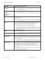
Message
K1-Close
Description / Remedial Action
Error during relay test.
K1-Open
MSD-Zac
• Contact the SMA Service Line if this disturbance occurs frequently
or several times in a row.
Internal measurement comparison fault or hardware defect.
MSD-Vac
• Contact the SMA Service Line if this disturbance occurs frequently.
MSD-Timeout
MSD-Zac
Offset
The "Offset" operating state is a normal operating state that occurs prior
to grid monitoring.
If "Offset" is displayed as an error, there is a disturbance in data logging.
Riso
• Contact the SMA Service Line if this disturbance occurs frequently.
The electrical insulation between the small wind turbine system and earth
is faulty. The resistance between the DC plus and/or DC minus
connection and earth is outside the defined limit range.
• Check the insulation of the small wind turbine system.
ROM
• Check the small wind turbine system for earth faults as described in
Section 9.3.1 "Checking the Small Wind Turbine System for Earth
Faults" (page 62).
The inverter firmware is faulty.
Shutdown
• Contact the SMA Service Line if this disturbance occurs frequently.
Temporary inverter disturbance.
Trafo-Temp-F
Trafo-Temp-W
• Contact the SMA Service Line.
Temperatures in the transformer have exceeded the permissible limit. The
inverter stops feeding into the grid until the temperature reverts to within
the permissible range.
• If this problem recurs, check the heat dissipation of the inverter, as
described in Section 8.2 "Checking Heat Dissipation" (page 52).
If the transformer reaches an unacceptably high temperature, the inverter
stops feeding energy to the grid until the temperature has reverted to
normal and the system can begin feeding into the grid again.
The "Trafo-Temp-W" warning is displayed until the device is completely
disconnected.
• Check the heat dissipation as described in Section 8.2 "Checking
Heat Dissipation" (page 52).
Installation Manual
WB33-38-IA-IEN120940
59
Troubleshooting
SMA Solar Technology AG
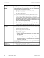
Message
Vac-Bfr
Description / Remedial Action
The line voltage is no longer within the permissible range ("Bfr" or "Srr" is
an internal message of no relevance for the user). This disturbance can
be caused by any of the following conditions:
Vac-Srr
• Grid disconnected (miniature circuit-breaker, fuse),
• AC cable is interrupted or
• AC cable is highly resistive.
The inverter disconnects from the electricity grid for safety reasons.
• Check the line voltage and grid connection on the inverter.
• If the line voltage is outside the permissible range because of local
grid conditions, ask the network operator if the voltages can be
adjusted at the feed-in point or if they will accept adjustments to the
values of the monitored operating limits
(operating parameters: Vac-Min and Vac-Max).
VpvMax
• If the line voltage is within the tolerance range, yet "Vac-Bfr" or
"Vac-Srr" faults are still displayed, contact the SMA Service Line.
Overvoltage at the DC input. This could damage the inverter.
Vpv-Max
Disconnect the small wind turbine system from the inverter immediately.
1. Stop the small wind turbine system.
2. Disconnect the miniature circuit-breaker.
3. Remove all DC connectors.
4. Check the DC voltage:
– If the DC voltage is above the maximum input voltage, check
the plant design.
– If the DC voltage is below the maximum input voltage,
reconnect the small wind turbine system to the inverter as
described in Section 5.5.4 "Connecting the Small Wind Turbine
System (DC)" (page 34).
If the message is repeated, disconnect the inverter again and contact the
SMA Service Line.
Internal disturbance of the program sequence.
Watchdog
Watchdog Srr
60
• Contact the SMA Service Line if this disturbance occurs frequently.
WB33-38-IA-IEN120940
Installation Manual
SMA Solar Technology AG
Message
Zac-Bfr
Zac-Srr
Troubleshooting
Description / Remedial Action
The grid impedance is outside the permissible range. The suffixes
"Bfr" und "Srr" are not relevant.
The inverter disconnects from the electricity grid for safety reasons. The
impedance is made up of both the grid impedance and the impedance
of the inverter AC cables.
• Check the grid impedance and grid connection at the inverter.
• Use an AC cable with an adequate cross-section
(= low impedance) as described in Section 5.3.2 "Connecting the
Inverter to the Electricity Grid (AC)" (page 25). If required, check
and re-tighten the screws on the AC plugs.
• Check the grid impedance and the AC connection on the inverter.
Use a cable with an adequate cross-section (= low impedance).
Observe the relevant advice in Section 5.3 "Connection to the
Electricity Grid (AC)" (page 23).
• If this fault recurs, please contact the SMA Service Line.
Installation Manual
WB33-38-IA-IEN120940
61
Troubleshooting
SMA Solar Technology AG
9.3 Red LED is Permanently On
If the red LED is permanently on during operation, this points either to an earth fault in the system or
at least one of the overvoltage protection varistors being defective.
In deliberately earthed systems, the red LED lights up as soon as the inverter has been commissioned.
However, this has no impact on the function of the inverter. Before you check the small wind turbine
system for an earth fault, check whether deliberate earthing has been carried out.
In deliberately earthed small wind turbine systems, check from time to time that the varistors in the
inverter are working properly, since a varistor fault can no longer be displayed.
9.3.1 Checking the Small Wind Turbine System for Earth Faults
DANGER!
Danger to life due to high voltages in the inverter
• Stop the small wind turbine system and secure against restarting.
• Disconnect the miniature circuit-breaker and secure against accidental or inadvertent
reconnection.
1. Wait until LEDs have gone out.
DANGER!
Danger to life due to high voltages in the inverter
The capacitors in the inverter take 15 minutes to discharge.
• Wait 15 minutes before opening the inverter.
2. Use a current probe to make sure no current is
present in the DC cables.
☑ If current is present, check the installation.
62
WB33-38-IA-IEN120940
Installation Manual
SMA Solar Technology AG
Troubleshooting
3. Release and disconnect all DC connectors. To do
this, insert a flat-blade screwdriver
(blade width: 3.5 mm) into one of the side slots and
pull the DC plug connectors out. Take care
NOT TO PULL ON THE CABLE.
4. Remove the AC connection socket from the inverter.
5. Disconnect L1, L2 and L3 of the small wind turbine system from the Windy Boy Protection Box.
6. Measure the resistance between the phases of the small wind turbine system and the earth
potential:
– Measure the resistance between L1 of the small wind turbine system and the earth potential.
– Measure the resistance between L2 of the small wind turbine system and the earth potential.
– Measure the resistance between L3 of the small wind turbine system and the earth potential.
Result
The measured resistance is virtually infinite.
What to do
There is probably an earth fault in the
☑ There is no earth fault in the small wind Windy Boy Protection Box or in the supply
cables to the inverter.
turbine system.
• Disconnect the Windy Boy Protection Box
from the inverter and measure the
resistance of all connections and the earth
potential.
Installation Manual
WB33-38-IA-IEN120940
63
Troubleshooting
SMA Solar Technology AG
Result
The measured resistance is very small
(< 10 Ω ).
What to do
• Have the installer of the small wind
turbine system eliminate the earth fault
before reconnecting the system to the
☑ There is an earth fault in the small wind
inverter.
turbine system.
64
WB33-38-IA-IEN120940
Installation Manual
SMA Solar Technology AG
Troubleshooting
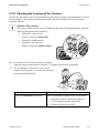
9.3.2 Checking the Function of the Varistors
Varistors are wear parts. Their functional efficiency diminishes with age or repeated strain as a result
of overvoltages. It is therefore possible that one of the thermally monitored varistors has lost its
protective function.
Position of the varistors
The position of the varistors can be located with the help of the diagram below. Note the
following assignment of the terminals:
• Terminal A: outer terminal
(varistor connection with crimp)
• Terminal B: middle terminal
• Terminal C: outer terminal
(varistor connection without crimp)
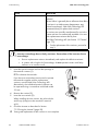
You can check the function of the varistors as follows:
1. Open the inverter as described in Section 7.2 "Opening the Inverter" (page 48).
2. Use a multimeter to check that in each of the
installed varistors there is a conductive connection
between terminals B and C.
Result
There is a conductive connection.
What to do
There is presumably a different error in the inverter.
1. Close the inverter as described in Section
7.3 "Closing the Inverter" (page 50).
2. Contact the SMA Service Line.
Installation Manual
WB33-38-IA-IEN120940
65
Troubleshooting
SMA Solar Technology AG
Result
There is no conductive connection.
What to do
The respective varistor is defective and must be
replaced.
Varistor failure is generally due to influences that affect
all varistors in a similar manner (temperature, age,
induced overvoltage). SMA Solar Technology AG
recommends that you replace both varistors.
The varistors are specially manufactured for use in the
inverter and are not commercially available. You must
order replacement varistors directly from
SMA Solar Technology AG (see Section 13 "Contact"
(page 77)).
• For the replacement of the varistors, proceed to
step 3.
NOTICE!
Inverter overvoltage due to faulty varistors. Destruction of the inverter due to
overvoltage
• Procure replacement varistors immediately and replace the defective varistors.
• In systems with a high risk of overvoltage, do not operate inverters with faulty
varistors or no varistors at all.
3. Insert the special insertion tool into the openings of
the terminal contacts (1).
☑ This releases the terminals.
If you have not received an insertion tool to operate
the terminals together with the replacement
varistors, contact SMA Solar Technology AG.
Alternatively, the individual terminal contacts can
be operated using a screwdriver with blade width
3.5 mm.
4. Remove the varistor (2).
5. Insert the new varistor (3).
When installing the new varistor, the pole with the
small loop (crimp) must be mounted in terminal
A (3).
6. Close the inverter as described in Section
7.3 "Closing the Inverter" (page 50).
☑ Testing and replacement of the varistors is now complete.
66
WB33-38-IA-IEN120940
Installation Manual
SMA Solar Technology AG
Decommissioning
10 Decommissioning
10.1 Dismantling the Inverter
1. Open the enclosure lid as described in Section 7.2 "Opening the Inverter" (page 48).
2. Remove all cables from the inverter.
3. Close the inverter with the 4 screws and the
corresponding conical spring washers.
4. Remove the ventilation grids on either side.
5. Remove the screw attaching the product to the wall
mounting bracket.
6. Remove the inverter from the wall mounting bracket
by lifting it vertically upwards.
☑ The inverter is now dismantled.
Installation Manual
WB33-38-IA-IEN120940
67
Decommissioning
SMA Solar Technology AG
10.2 Packing the Inverter
If possible, always pack the inverter in its original packaging. If this is no longer available, you can
also use an equivalent box. The box must be completely closeable and suitable for the weight and
size of the inverter.
10.3 Storing the Inverter
Store the inverter in a dry place where ambient temperatures are always between
‒25°C and +60°C.
10.4 Disposing of the inverter
Dispose of the inverter at the end of its service life in accordance with the disposal regulations for
electronic waste which apply at the installation site at that time. Alternatively, send it back to
SMA Solar Technology AG with shipping paid by sender, and labelled "ZUR ENTSORGUNG"
("For Disposal") (see Section 13 "Contact" (page 77)).
68
WB33-38-IA-IEN120940
Installation Manual
SMA Solar Technology AG
Technical Data
11 Technical Data
11.1 DC/AC
11.1.1 Windy Boy 3300
DC input
Turbine control
Maximum DC power at cos φ = 1
Recommended generator power at
2 500 full-load hours per year
Recommended generator power at
5 000 full-load hours per year
Maximum input voltage
DC voltage range
Rated input voltage
Minimum input voltage
Start input voltage
Maximum input current
Maximum input current per string
Number of independent DC inputs
Strings per MPP input*
Polynomial Curve
3 820 W
3 100 W
2 800 W
500 V
200 V … 500 V
200 V
200 V
250 V
20 A
16 A
1
3
* For WB 3300-11 / WB 3800-11: 2 strings per MPP input
Installation Manual
WB33-38-IA-IEN120940
69
Technical Data
SMA Solar Technology AG
AC output
Rated power at 230 V, 50 Hz
Maximum apparent AC power
Rated line voltage
AC nominal voltage
AC voltage range
Nominal AC current at 220 V
Nominal AC current at 230 V
Nominal AC current at 240 V
Maximum output current
Total harmonic factor of the output current at total
harmonic factor of the AC voltage < 2%,
and AC power > 50% rated power
Rated power frequency
AC power frequency
Operating range at AC power frequency 50 Hz
Operating range at AC power frequency 60 Hz
Displacement power factor, adjustable*
Power factor at nominal AC power**
Feed-in phases
Connection phases
Overvoltage category according to IEC 60664-1
3 300 W
3 600 VA
230 V
220 V / 230 V / 240 V
180 V … 265 V
15 A
14.3 A
13.8 A
18 A
≤ 3%
50 Hz
50 Hz / 60 Hz
+5 Hz / − 6 Hz
+5 Hz / − 6 Hz
0.8 overexcited … 0.8 underexcited
1
1
1
III
* for WB 3300-11
** for WB 3300/WB 3300-IT
Efficiency
Maximum efficiency, ηmax
European weighted efficiency, ηEU
70
WB33-38-IA-IEN120940
95.2%
94.4%
Installation Manual
SMA Solar Technology AG
Technical Data
11.1.2 Windy Boy 3800
DC input
Turbine control
Maximum DC power at cos φ = 1
Recommended generator power at
2 500 full-load hours per year
Recommended generator power at
5 000 full-load hours per year
Maximum input voltage
DC voltage range
Rated input voltage
Minimum input voltage
Start input voltage
Maximum input current
Maximum input current per string
Number of independent DC inputs
Strings per MPP input*
Polynomial Curve
4 040 W
3 600 W
3 300 W
500 V
200 V … 500 V
200 V
200 V
250 V
20 A
20 A
1
3
* For WB 3300-11 / WB 3800-11: 2 strings per MPP input
Installation Manual
WB33-38-IA-IEN120940
71
Technical Data
SMA Solar Technology AG
AC output
Rated power at 230 V, 50 Hz
Maximum apparent AC power
Rated line voltage
AC nominal voltage
AC voltage range
Nominal AC current at 220 V
Nominal AC current at 230 V
Nominal AC current at 240 V
Maximum output current
Total harmonic factor of the output current at total
harmonic factor of the AC voltage < 2%,
and AC power > 50% rated power
Rated power frequency
AC power frequency
Operating range at AC power frequency 50 Hz
Operating range at AC power frequency 60 Hz
Displacement power factor, adjustable*
Power factor at nominal AC power**
Feed-in phases
Connection phases
Overvoltage category according to IEC 60664-1
3 800 W
3 800 VA
230 V
220 V / 230 V / 240 V
180 V … 265 V
17.3 A
16.5 A
15.8 A
18 A
≤ 3%
50 Hz
50 Hz / 60 Hz
+/ − 4.5 Hz
+/ − 4.5 Hz
0.8 overexcited … 0.8 underexcited
1
1
1
III
* for WB 3800-11
** for WB 3800/WB 3800-IT
Efficiency
Maximum efficiency, ηmax
European weighted efficiency, ηEU
72
WB33-38-IA-IEN120940
95.6%
94.7%
Installation Manual
SMA Solar Technology AG
Technical Data
11.2 General data
Width x height x depth
450 mm x 350 mm x 236 mm
Weight
38 kg
Length x width x height of packaging
580 mm x 470 mm x 390 mm
Transport weight
43.7 kg
Climatic category (according to IEC 60721-2-1)
4K4H
Operating temperature range
− 25°C … +60°C
Maximum permissible value for relative humidity,
100%
non-condensing
Maximum operating altitude above Mean Sea
2 000 m
Level
Noise emission (typical)
≤ 42 dB(A)
Power loss in night operation
0.10 W
Topology
LF transformer
Cooling concept
OptiCool: temperature-controlled fan
Fan connection
designed for safe disconnection in accordance
with
Electronics protection rating according to
IEC 60529
Protection class (according to IEC 62103)
DIN EN 50178:1998-04
IP65
I
11.3 Protective Devices
DC reverse polarity protection
Input-side disconnection device
DC overvoltage protection
AC short-circuit current strength
Grid monitoring
Maximum permissible fuse protection
Earth fault monitoring
Galvanic isolation
Installation Manual
Short-circuit diode
Electronic Solar Switch
Thermally monitored varistors
Current control
SMA Grid Guard X
25 A
Insulation monitoring: Riso > 1 MΩ |
Available
WB33-38-IA-IEN120940
73
Technical Data
SMA Solar Technology AG
WB 3300-11
WB 3800
WB 3800-IT
WB 3800-11
VDE0126-1-1
VDE-AR-N 4105
VDE0126-1-1 / UTE C15-712-1
UTE C15-712-1 / EDF SEI req.
DK5940
PPC
RD 1663/2000
RD 661/2007
AS 4777
G83/1-1
EN 50438*
C10/11
WB 3300-IT
Country standard,
as per 12/2011
WB 3300
11.4 Licences
✓
‒
‒
✓
‒
✓
✓
✓
✓
✓
✓
✓
‒
‒
‒
‒
✓
‒
‒
‒
‒
‒
‒
‒
✓
✓
✓
‒
‒
‒
‒
‒
‒
‒
‒
‒
✓
‒
‒
✓
‒
✓
✓
✓
✓
✓
✓
✓
‒
‒
‒
‒
✓
‒
‒
‒
‒
‒
‒
‒
✓
✓
✓
‒
‒
‒
‒
‒
‒
‒
‒
‒
* EN 50438: not applicable to all deviations from the national standard
11.5 Climatic Conditions
According to IEC 60721-3-4, installation type C, class 4K4H
Extended temperature range
Extended humidity range
Extended air pressure range
− 25°C … +60°C
0% … 100%
79.5 kPa … 106 kPa
According to IEC 60721-3-2, transport type E, class 2K3
Temperature range
− 25°C … +70°C
11.6 Features
DC connection
AC connection
Display
Bluetooth® Wireless Technology
RS485, galvanically isolated
74
WB33-38-IA-IEN120940
SUNCLIX DC connector
AC connector
LC text display |
Optional
Optional
Installation Manual
SMA Solar Technology AG
Technical Data
11.7 Torques
Enclosure lid screws
Additional earthing screw
Cheese-head screw for attaching enclosure to
wall mounting bracket
SUNCLIX swivel nut
RS485 communication connection
6.0 Nm
6.0 Nm
6.0 Nm
2.0 Nm
1.5 Nm
11.8 Distribution systems
IT system
TN-C system
TN-S system
TN-C-S system
TT system
Split-phase
Installation Manual
suitable
suitable
suitable
suitable
suitable
suitable
WB33-38-IA-IEN120940
75
Accessories
SMA Solar Technology AG
12 Accessories
You will find the accessories and spare parts corresponding to your specific inverter in the following
overview. If required, you can order these from SMA Solar Technology AG or your dealer.
Designation
Windy Boy Protection Box
Ventilation grid
Replacement varistors
Insertion tool for
replacement of varistors
RS485 retrofit kit
Bluetooth® Wireless
Technology retrofit kit
SUNCLIX DC plug
connector
76
Brief description
Rectifier and overvoltage protection for small
wind turbine systems with Windy Boy
Ventilation grid set "right and left" as spare
parts
Set of thermally controlled varistors (2 pcs.)
including insertion tool
Insertion tool for varistors
SB-TVWZ
RS485 communication interface
Bluetooth communication interface
485PB-NR
BTPBINV-NR
Field plug for conductor cross-sections
2.5 mm² … 6 mm²
SUNCLIX-FC6-SET
WB33-38-IA-IEN120940
SMA order number
WBP-Box 500
45-7202
SB-TV 4
Installation Manual
SMA Solar Technology AG
Contact
13 Contact
If you have technical problems concerning our products, contact the SMA Service Line. We require
the following information in order to provide you with the necessary assistance:
• Inverter type
• Inverter serial number
• Type of connected small wind turbine system
• Optional equipment, e.g. communication products
• Blink code or display message of the inverter
SMA Solar Technology AG
Sonnenallee 1
34266 Niestetal, Germany
www.SMA.de
SMA Serviceline
Inverters:
+49 561 9522 1499
Communication: +49 561 9522 2499
Fax:
+49 561 9522 4699
E-Mail:
[email protected]
Installation Manual
WB33-38-IA-IEN120940
77
SMA Solar Technology AG
Legal Restrictions
The information contained in this document is the property of SMA Solar Technology AG. Publishing its content, either partially or
in full, requires the written permission of SMA Solar Technology AG. Any internal company copying of the document for the
purposes of evaluating the product or its correct implementation is allowed and does not require permission.
SMA Factory Warranty
The current warranty conditions come enclosed with your device. These are also available online at www.SMA.de and can be
downloaded or are available on paper from the usual sales channels if required.
Trademarks
All trademarks are recognized even if these are not marked separately. Missing designations do not mean that a product or brand
is not a registered trademark.
The Bluetooth® word mark and logos are registered trademarks owned by Bluetooth SIG, Inc. and any use of such marks by
SMA Solar Technology AG is under licence.
SMA Solar Technology AG
Sonnenallee 1
34266 Niestetal
Germany
Tel. +49 561 9522-0
Fax +49 561 9522-100
www.SMA.de
E-Mail: [email protected]
© 2004 to 2012 SMA Solar Technology AG. All rights reserved
Installation Manual
WB33-38-IA-IEN120940
79
4."4PMBS5FDIOPMPHZ
XXX4."4PMBSDPN
4."4PMBS5FDIOPMPHZ"(
XXX4."EF
4.""NFSJDB --$
XXX4.""NFSJDBDPN
4."5FDIOPMPHZ"VTUSBMJB1UZ -UE
XXX4.""VTUSBMJBDPNBV
4."#FOFMVY413XXX4."#FOFMVYDPN
4."#FJKJOH$PNNFSDJBM$P -UE
XXX4."$IJOBDPN
4."$[FDI3FQVCMJDTSP
XXX4."$[FDIDPN
4."'SBODF4"4
XXX4."'SBODFDPN
4.")FMMBT"&
XXX4.")FMMBTDPN
4."*C©SJDB5FDOPMPHB4PMBS 4-
XXX4."*CFSJDBDPN
4."*UBMJB4SM
XXX4."*UBMJBDPN
4."5FDIOPMPHZ,PSFB$P -UE
XXX4.",PSFBDPN