1
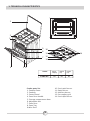
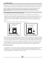
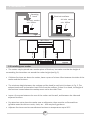
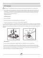
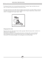
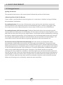
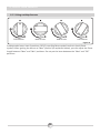
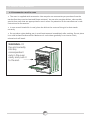
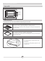
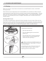
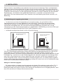
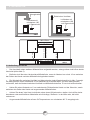
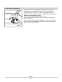
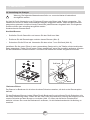
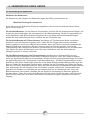
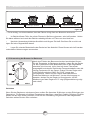
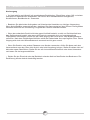
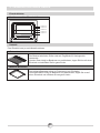
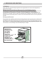
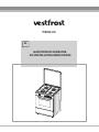
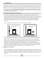
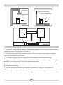
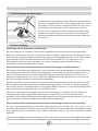
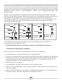
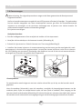
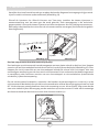
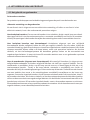
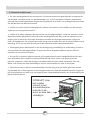
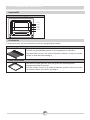
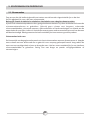
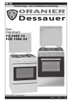
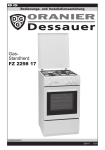
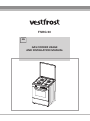
FSHG 60
EN
GAS COOKER USAGE
AND INSTALLATION MANUAL
Dear Customer,
We take offering quality products more than your expectation as goal, offers you
the products produced in modern facilities where each cooker was carefully and
particularly tested for quality.
This leaflet contains all the necessary information for installing and using
your new cooker.
Before you begin using your new cooker, we suggest you read this leaflet carefully
because it contains all the basic information for proper and reliable installation,
proper use and regular maintenance of your cooker. This cooker must be installed
only by a qualified professional in accordance with safety standards and laws.
Never attempt to repair your cooker on your own.
CE Declaration of conformity
This cooker is only for domestic use inside a house (excluding professional use).
Any other use (such as heating a room) is improper and dangerous.
This cooker has been designed, constructed, and marketed incompliance with:
Safety requirements of the "Gas" Directive 2009/142/EC ;
Requirements of the Directive 93/68/EC.
CONTENTS
1. TECHNICAL CHARACTERISTICS
2. WARNINGS
General safety warnings
Installation warnings
During usage
During cleaning and maintenance
3. INSTALLATION
3.1 Installation environment for your cooker
3.2 Installing your cooker
3.3 Adjusting the feet
3.4 Gas connection
3.5 Changing gas
4. USE OF YOUR PRODUCT
4.1 Using gas burners
4.1.1 Using cooktop burners
4.1.2 Using the gas oven burner
4.2 Accessories used in oven
5. CLEANING AND MAINTENANCE
5.1 Cleaning
5.2 Maintenance
6. SERVICE AND TRANSPORT
6.1 Requirements before contacting the customer service
6.2 Information on transport
2
1. TECHNICAL CHARACTERISTICS
1
2
3
9 10
8
11
7
4
14
12
13
5 6
MODEL
FSHG 60
Cooker parts list:
1- Cooktop Cover
2- Cooktop
3- Control Panel
4- Oven Door Handle
5 - Storage compartment door
6- Adjustable feet
7- Oven Door
8- Oven Tray
9-Wire Shelf
3
DEPTHSIZE(cm)
LENGTH
(cm)
HEIGHT
(cm)
60
60
85
10- Semi-rapid burner
11- Rapid burner
12- Auxiliary burner
13- Pan support grid
14- Semi-rapid burner
2. WARNINGS
READ THESE INSTRUCTIONS CAREFULLY AND COMPLETELY BEFORE USING YOUR
APPLIANCE, AND KEEP IT IN A CONVENIENT PLACE FOR REFERENCE WHEN NECESSARY.
THIS MANUAL IS PREPARED FOR MORE THAN ONE MODEL IN COMMON. YOUR APPLIANCE
MAY NOT HAVE SOME OF THE FEATURES THAT ARE EXPLAINED IN THIS MANUAL. PAY
ATTENTION TO THE EXPRESSIONS THAT HAVE FIGURES, WHILE YOU ARE READING THE
OPERATING MANUAL.
General Safety Warnings
- This appliance is intended for domestic household
use only and should not be used for any other purpose
or in any other application, such as for non-domestic
use or in a commercial environment.
- If the supply cord is damaged, it must be replaced
by the manufacturer, its service agent or similarly
qualified persons in order to avoid a hazard.
- This appliance can be used by children aged
from 8 years and above and persons with
reduced physical, sensory or mental capabilities
or lack of experience and knowledge if they
have been given supervision or instruction
concerning use of the appliance in a safe way
and understand the hazards involved. Children
shall not play with the appliance. Cleaning and
user maintenance shall not be made by children
without supervision.
- WARNING: The appliance and its accessible
parts become hot during use. Care should be
taken to avoid touching heating elements.
Children less than 8 years of age shall be kept
away unless continuously supervised.
- WARNING: Unattended cooking on a hob with
4
2. WARNINGS
fat or oil can be dangerous and may result in
fire. NEVER try to extinguish a fire with water,
but switch off the appliance and then cover
flame e.g. with a lid or a fire blanket.
- WARNING: Danger of fire: do not store items
on the cooking surfaces.
- Any spillage should be removed from the lid
before opening.
- The hob surface should be allowed to cool
before closing the lid.
- The appliance is not intended to be operated
by means of an external timer or separate
remote-control system.
- During use, the appliance becomes hot. Care
should be taken to avoid touching heating
elements inside the oven.
- Do not use harsh abrasive cleaners or sharp
metal scrapers to clean the oven door glass
since they can scratch the surface, which may
result in shattering of the glass.
- Do not use steam cleaners for cleaning the
appliance.
- CAUTION: Accessible parts may become hot
during use. Young children should be kept
away.
• Your appliance is produced in accordance with all applicable local and international
standards and regulations.
5
2. . WARNINGS
• Maintenance and repair work must be made only by authorised service technicians.
Installation and repair work that is carried out by unauthorised technicians may endanger
you. It is dangerous to alter or modify the specifications of the appliance in any way.
• Prior to installation, ensure that the local distribution conditions (nature of the gas and
gas pressure) and the requirements of the appliance are compatible. The requirements for
this appliance are stated on the label.
• Do not try to lift or move the appliance by pulling the door handle.
• This appliance is not connected to a combustion products evacuation device. It shall be
installed and connected in accordance with current installation regulations. Particular
attention shall be given to the relevant requirements regarding ventilation.
• If after 15 s the burner has not lit, stop operating the device and open the kitchen door
or window and/or wait at least 1 min before attempting a further ignition of the burner.
• These instructions are only valid if the country symbol appears on the appliance. If the
symbol does not appear on the appliance, it is necessary to refer to the technical
instructions which will provide the necessary instructions concerning modification of the
appliance to the conditions of use of the country.
• All possible security measures have been taken to ensure your safety. Since the glass
may break, you should be careful while cleaning to avoid scratching. Avoid hitting or
knocking on the glass with accessories.
• While the oven door is open, do not let children climb on the door or sit on it.
Installation Warnings
• Do not operate the appliance before it is fully installed.
• The appliance must be installed by an authorised technician and put into use. The
producer is not responsible for any damage that might be caused by defective placement
and installation by unauthorised people.
• When you unpack the appliance, make sure that has not been damaged during
transportation. In case of any defect; do not use the appliance and contact a qualified
service agent immediately. As the materials used for packaging (nylon, staplers,
styrofoam...etc) may cause harmful effects to children, they should be collected and
removed immediately.
• Protect your appliance against atmospheric effects. Do not expose it to effects such as sun,
rain, snow etc.
• The surrounding materials of the appliance (cabinet) must be able to withstand a
temperature of min 100°C.
During usage
• When you first run your oven a certain smell will emanate from the insulation materials.
For this reason, before using your oven, run it empty at maximum temperature for 45
minutes. At the same time you need to properly ventilate the environment in which the
product is installed.
• During usage, the outer and inner surfaces of the oven get hot. While opening the oven
door, step back to avoid the hot steam coming out of the oven. There may be a risk of
burns.
• Do not put flammable or combustible materials, in or near the appliance when it is
operating.
• Always use oven gloves to remove and replace food in the oven.
6
2. . WARNINGS
• Do not leave the cooker while cooking with solid or liquid oils. They may catch fire on
condition of extreme heating. Never pour water on to flames that are caused by oil. Cover
the saucepan or frypan with its cover in order to choke the flame that has occured in this case
and turn the cooker off.
• Always position pans over the centre of the cooking zone, and turn the handles to a safe
position so they cannot be knocked or grabbed.
• If you will not use the appliance for a long time, plug it off. Keep the main control switch off. Also when
you do not use the appliance, keep the gas valve off.
• Make sure the appliance control knobs are always in the "0" (stop) position when it is not used.
• The trays incline when pulled out. Be careful not to let hot liquid spill over.
• CAUTION: The use of a gas cooking appliance results in the production of heat, moisture and products
of combustion in the room in which it is installed. Ensure that the kitchen is well ventilated especially
when the appliance is in use, keep natural ventilation holes open or install a mechanical ventilation
device (mechanical extractor hood).
• Prolonged intensive use of the appliance may call for additional ventilation, for example opening of
a window, or more effective ventilation, for example increasing the level of mechanical ventilation
where present.
• CAUTION:
Turn off all the burners before shutting the lid.
The hob surface should be allowed to cool before closing the lid.
• When the door or drawer of the oven is open, do not leave anything on it. You may unbalance your
appliance or break the cover.
• Do not put heavy things or flammable or ignitable goods (nylon, plastic bag, paper, cloth...etc) into
the drawer. This includes cookware with plastic accessories (e.g. handles).
During cleaning and maintenance
• Always turn the appliance off before operations such as cleaning or maintenance. You can do it
after plugging the appliance off or turning the main switches off.
• Do not remove the control knobs to clean the control panel.
TO MAINTAIN THE EFFICIENCY AND SAFETY OF YOUR APPLIANCE, WE RECOMMEND YOU
ALWAYS USE ORIGINAL SPARE PARTS AND TO CALL ONLY OUR AUTHORISED
SERVICE AGENTS IN CASE OF NEED.
7
3. INSTALLATION
This modern, functional and practical cooker that was manufactured with the parts and materials
of highest quality will meet your cooking needs in every aspect. Before using your cooker, please
read this leaflet carefully to find out all its functions and achieve the best possible results. For
proper installation, consider the following recommendations to avoid any problem or
dangerous situation. They must also be read by the technician who will install the cooker.
3.1 Installation environment for your cooker
• Your cooker must be set up and used in a place where it will always have ventilation. Gas
combustion is made possible by the oxygen in the air. It is therefore necessary that the air be
renewed and that combustion products be discharged in accordance with the regulations. There
must be a natural ventilation enough to provide the gas to be used in the environment. The
airflow must enter via vents installed on walls in direct contact with the outside (see diagram
below).
• While operating, this cooker needs 2m3 /h air per kw input.
Air inlet section
min. 100cm
Air inlet section
min. 100cm
2
2
Figure 2
Figure 1
• The airflow must enter through the bottom (minimum 100cm ²) and come out on top (minimum
100cm ²). These vents must therefore have a minimum area of 100 cm2 for the effective passage
of air. These vents should be open and never closed. They should preferably be located near the
rear of the cooker (for the air inlet Fig. 1 and 2) and opposite the burnt gases caused by cooking
(for evacuation) that is to say at least 1.80m above the ground. If you cannot open these vents
toto the outside, where the cooker is installed, the necessary air may also come from another
location provided it is properly ventilated and is neither a bedroom nor a dangerous place.
Evacuating burnt gases
It is advisable to install either an exhaust hood directly connected to a pipe leading directly to the
outside (Fig. 3), or an electrical ventilator installed on the window or outside wall (Fig. 4) to
evacuate flue gases directly outside. The electrical ventilator power supply must be calculated in
order to renew the air in the kitchen 4-5 times per hour.
8
3. INSTALLATION
Extracting
hood
Electrical ventilator
Air inlet section
min. 100cm
Air inlet section
min. 100cm
2
2
Figure 3
Figure 4
Min. 60cm
Min. 42cm
Min. 65cm (with hood)
Min. 70cm (without hood )
Min. 42cm
COOKER HOOD
Figure 5
3.2 Installing your cooker
• The cooker may be placed near another piece of furniture, but make sure that the height of
surrounding furniture does not exceed the cooker height (see fig. 5).
• If kitchen furniture are above the cooker, leave a space of at least 10cm between the sides of the
cooker and the furniture.
• The minimum height between the cooktop and the hood (or wall units) is shown in Fig. 5. The
exhaust hood must be located at least 65cm from the cooktop. If there is no hood, the height of
the furniture located above the cooktop must not be less than 70cm.
• Leave a 2cm space between the rear of the cooker and the wall, and between the sides and
adjacent furniture.
• Pay attention not to place the cooker near a refrigerator; there must be no flammable or
ignitable materials such as curtain, cloth, etc... that may easily get burnt.
• Adjacent furniture must be manufactured resistant to temperatures up to 90°C.
9
3. INSTALLATION
3.3 Adjustment of feet
Your product stands on 4 adjustable feet. When the product is
placed where to be used, check if the product is balanced. If it
is not balanced, you can make the adjustment by turning the
feet clockwise if required. It is possible to raise the appliance
maximum 30mm by the feet. If the feet are adjusted
appropriately, it is required not to move the appliance by
dragging, it should be moved by lifting it up.
Figure 6
3.4 Gas connection
Assembly of gas supply and leakage check
The connection of the appliance should be performed in accordance with local and international
standards and regulations applicable. You can find the information related to appropriate gas types
and appropriate gas injectors on technical data table. If the pressure of used gas is different than
these values stated or not stable in your area, it may be required to assemble an available pressure
regulator on the gas inlet. It is certainly required to contact to the authorized service to make these
adjusments.
The points that must be checked during flexible hose assembly
If the gas connection is made by a flexible hose that is fixed on the gas inlet of appliance, it must be
fixed by a pipe collar as well. Connect your appliance with a short and durable hose that is as close
as possible to the gas source. The hose's permitted maximum lenght is 1.5m. The hose that brings
gas to the appliance must be changed once a year for your safety.
The hose must be kept clear from areas that may heat up to temperatures in excess of 900C. The
hose must not be ruptured, bent or folded. It must be kept clear of sharp corners, moving things,
and should not be defective. Before assembly, it must be checked whether there is any production
defect.
As gas is turned on, all connection parts and hose must be checked with soapy water or leakage
fluids. Do not use naked flame to check gas leakage. All metal components used during gas
connection must be clear of rust. Also check the expiry dates of components to be used.
The points that must be checked during fixed gas connection assembly
To assemble a fixed gas connection (gas connection made by threads, e.g. a nut), there are different
methods used in different countries. The most common parts are already supplied with your appliance.
Any other part can be supplied as spare part.
During connections always keep the nut on the gas manifold fixed, while rotating the counter-part. Use
spanners of appropriate size for safe connection. For all surfaces between different components,
9
3. INSTALLATION
always use the seals provided in the gas conversion kit. The seals used during connection should
also be approved to be used in gas connections. Do not use plumbing seals for gas connections.
Remember that this appliance is ready to be connected to gas supply in the country for which it has
been produced. The main country of destination is marked on the rear cover of the appliance. If you
need to use it in another country, any of the connections in the figure below can be required. In
such a case, learn the appropriate connection parts and obtain those parts to perform a safe
connection.
Gas Pipe
Seal
Gas Pipe
Gas Pipe
Gas Pipe
Seal
Hose
Fitting
Adapter
Gas Hose
with Collar
Mechanical
Gas Hose
Seal
Mechanical
Gas Hose
Mechanical
Gas Hose
It is required to call the authorized service to be able to make the gas connections appropriately
and in compliance with safety standards.
ATTENTION! Surely do not use any match or lighter for control of gas leakage.
The gas inlet of this product is on the right side of the appliance. If connection point needs to be
moved to the left side of the appliance, you can request an extension pipe from your authorized
service.
3.5 Electric connection and safety
During the electric connection, follow the instructions stated in the user manual.
• The earthing cable must be connected to the earth terminal.
• You have to ensure the power cord with suitable insulation to be connected to the power source
during the connection. If there is no appropriate earthed electric outlet in accordance with
regulations in the place where the appliance to be installed, contact to our authorized service.
The earthed electric outlet must be close to the appliance.
• Do not use an extension cord.
• The power cord must not touch to the hot surface of the product.
• In case the cord is damaged, contact Authorized Service to have it changed.
• Any wrong electric connection may damage your appliance, as well as endangering your safety,
rendering your guarantee invalid.
10
3. INSTALLATION
3.6 Changing gas
! Warning : The following procedures must be undertaken by authorised service personnel.
Your cooker has been designed to use either liquefied petroleum gas (propane or butane), or
natural gas. The gas burners can be adapted to these different types of gas, by replacing the
corresponding injectors and adjusting the minimum flame length of each burner. The steps
below must be strictly carried out:
Changing Injectors:
Cooktop burners:
• Shut off main gas.
• Remove the burner cap and the upper burner (Figure 8).
• Unscrew the injectors. For this, use a 7mm spanner (Figure 9).
• Install the new injectors in accordance with the type of gas used, as shown on the technical data
table. Be careful to tighten straight the new injectors, because if you mount them sideways, you will
damage the thread of the rack and the rack will need to be changed (and it will not be in guarantee
extent).
Spanner
Injector
Figure 9
Figure 8
Oven Injectors :
The oven burners are fitted by a single screw that is placed on the tip of the burner.
For the oven burner (below), open the oven door, remove the screws holding the lower sheet.
Open the compartment beneath the oven (pull-down door) to access the front screw located on
the burner (Figure 11). If the cooker has a sub-oven front , you must first dismantle the oven
door to gain access to the screws holding the sheet.
12
3. INSTALLATION
Remove the burner screw, and move the burner diagonally to access the injector at the rear
bottom of the muffle oven (Figure 11).
Unscrew the injectors. For this, use a 7mm spanner. Install the new injectors in accordance with
the type of gas used, as shown on the technical data table. Be careful to tighten straight the new
injectors, because if you mount them sideways, you will damage the thread of the rack and the
rack will need to be changed (and it will not be in guarantee extent).
Screw
Injector
Figure 10
Figure 11
Adjusting the flame to minimum on the valve
The flame length at minimum position is adjusted with a flat screw located on the valve. For valves
with thermocouple, the screw is located on the side of the valve spindle (Figure 12).
To determine the min. position, ignite the burners one after another and set them at minimum
position. With the help of a small screwdriver fasten or loosen the by pass screw around 90
degrees. When the flame has a length of at least 4mm, the adjustment is correct. For control, make
sure that the flame does not die out when passing from the maximum position to the minimum
position. Create an artificial wind with your hand toward the flame to see if the flames are stable.
Valve with thermocouple
Bypass screw
Figure 12
13
Valve without flame failure device
3. INSTALLATION
For the oven burner, let it run at minimum position for 5 minutes. Open and close the oven
door 2-3 times to check the stability of the burner flame.
During the conversion from LPG to NG, the bypass screw must be unscrewed. When converting
from NG to LPG, the same screw must be tightened up. During this adjustment, make sure the
cooker is unplugged and the gas supply is open.
Screw(inside the hole)
Figure 15
Changing the Gas Inlet:
Regularly check the expiry date of your cooker gas pipe. When the expiry date is reached, it is
necessary to change the hose.
These pipes are available on the market and must be consistent with current standards.
After changing the hose, you should check that there is no leakage by referring to the
information in the above paragraph: Connecting gas and checking leakage.
B
Figure 17
14
4. USE OF YOUR PRODUCT
4.1 Using gas burners
Igniting the burners
The symbols of the levers on the control panel indicate the position of the burner.
•Manual Ignition of the Gas Burners
If your cooker is not fitted with electrical ignition or in case there is a failure in the grid, follow
the procedures listed below:
For cooktop burners: To turn one of the burners, press and turn the valve lever concerned
counterclockwise until maximum position and immediately ignite a match or gas lighter near
the crown burner holes. Move the ignition source away as soon as you see a stable flame.
For cooktop burners with thermocouple: Cooktops fitted with safety thermocouple provide
security when the flame goes out accidentally. For this reason, during the manual ignition, press
and hold the valve lever until you see stable flames. If the flames remain unstable after releasing
the button, repeat the procedure. If the flame goes out, the thermocouple system will close off
the said gas valve towards the burner and will prevent any accumulation of unburned gas. You
must wait at least 90 seconds before re-igniting a gas burner after an automatic cut.
For the oven burner (fitted with thermocouple): All oven burners are fitted with safety
thermocouple and provide security when the flame goes out accidentally. To ignite the oven
burner, press and turn the oven valve lever counterclockwise until it reaches maximum position.
While pressing the lever, immediately ignite a match or gas lighter near the ignition hole located
on the left front of the burner. Once the burner is lit with a steady flame, withdraw the ignition
source at once and hold pressed for about 3 seconds. If the flames remain cut out after
releasing the knob, repeat the procedure. If the flame goes out, the thermocouple system will
shut off the gas inlet of the oven valve towards the burner and will prevent any accumulation of
unburned gas. If the oven burner does not ignite after you keep the burner knob pressed for at
least 30 seconds, open the oven door and do not attempt re-ignition until at least 90 seconds.
When oven flames go out accidentally, repeat the same procedure.
15
4. USE OF YOUR PRODUCT
4.1.1 Using cooktop burners
Off Position
MAX Position
MIN Position
Intermediate
Figure 14
Cooktop valve levers have 3 positions: Off (0), max (big flame symbol) and min (small flame
symbol). After igniting the burner to "Max" position (as explained above), you can adjust the flame
length between "Max" and "Min" positions. Do not put the lever between the "Max” and “Off”
positions.
16
4. USE OF YOUR PRODUCT
After the ignition, check the flames visually. If you see
yellow tip, lifted or unstable flames; turn the gas flow off,
and check the position of burner caps and crowns (fig.15).
Take note: these are very hot, let them cool to avoid burning
yourself. Be careful that no liquid flows inside the burners. If
the flames accidentally escape from the burner, close the
valves, ventilate the kitchen with fresh air, and wait at least 90
seconds before re-igniting.
Cap
Crown
Burner
To stop the cooking, turn the burner lever clockwise until the
mark on the lever is facing the point "0" (lever mark up).
Figure 15
Your cooktop is fitted with burners of different diameters. In order to obtain the most efficiency
from the cookers, pay attention to the sizes of saucepans that you put the on the cookers and
make sure that the saucepans have flat bases. Do not use saucepans with concave or convex
bottom to avoid wasting energy. Use proper-sized saucepans corresponding to the flame; if you
use containers smaller than those specified below, you will have wasted energy. The cheapest
way to use the gas is to reduce the flame to minimum position once you reach boiling point. It is
recommended to always cover your cooking pan.
Rapid Burner: 22-26cm
Semi-rapid burner 14-22cm
Auxiliary burner: 12-18cm
Figure 16
When not using your cooker for a long while, always close the gas inlet valve.
! WARNING:
• Use only flat pans.
• Ensure that the base of the pan is dry before placing it on the burners.
17
4. USE OF YOUR PRODUCT
• It is important to ensure that the pan is centered correctly above the burners.
• The temperature of parts exposed to the flame can be very high when in use. So, it is imperative
to keep children and animals out of the reach of the burners during and after cooking.
• After use, the cooktop remains hot for a long time. Do not touch it and do not place objects on
it.
4.1.2 Using the gas oven burner
290
230
150
After igniting the oven burner as explained above, you may
adjust the temperature inside the oven, by positioning the
control in front of the signs on the control panel. If your oven
is fitted with an oven thermostat; refer to the temperature
table below to select temperature according to the food
cooked. Do not operate the oven by placing the lever
between the "Off" position and the point indicating min
temperature (counterclockwise). Always use the oven
between the maximum and minimum positions. To stop the
cooking, turn the burner lever clockwise until the mark on the
Figure 18 lever is facing the point "0" (lever mark up).
Preheating
When you need to preheat the oven, we recommend you do so 10 minutes before placing a dish.
For recipes needing high temperatures, e.g. bread, pastries, scones, souffles, etc..., best results
are achieved if the oven is preheated first. For best results when cooking frozen or chilled food
always preheat the oven first.
Cooking
• Your cooker has been delivered with wire shelf and oven tray. You may also use glass dishes,
cake pans, oven plates specially adapted to oven baking, which you may find on the market.
• Make sure you follow the instructions given by the manufacturer on the possible use of the
dishes. If small sized containers are used, place them on the shelf such that they are precisely in
the middle of the wire. The following instructions should also be followed for all glazed dishes.
• If food for cooking does not cover the entire surface of the cooktop, if it is food from the freezer,
the tray may undergo changes in shape due to high temperatures caused by cooking. The tray
will take back its original shape only when it has completely cooled after cooking. This is a
perfectly normal phenomenon caused by heat transfer.
• If you use dishes and other glassware for cooking, do not expose directly to cold after taking
them out of the oven. Do not place on cold or wet surfaces. Place them on a dry kitchen towel or
on a trivet, and make sure they cool slowly, so as to prevent them from breaking.
• Be careful not to put the oven tray on the bottom of the oven because it may overheat and
damage the oven enamel.
18
4. USE OF YOUR PRODUCT
4.2 Accessories used in oven
• The oven is supplied with accessories. You may also use accessories you purchase from the
market (but they must be heat and flame resistant). You can also use glass dishes, cake moulds,
special oven trays that are appropriate for use in oven. Pay attention to the manufacturer's user
instructions for accessories.
• In case a small-sized dish is used, place the dish at the centre of the grid so that stands
correctly.
• Do not place a glass baking pan in a cold environment immediately after cooking. Do not place
it on cold and wet surfaces either. Make sure it cools down gradually on a trivet or cloth,
otherwise it will break.
WARNING- Fit
the grid correctly
into any
correspondent
rack in the oven
cavity and push it
to the end.
19
4. USE OF YOUR PRODUCT
Oven muffle
Positions on moulded slides
Position 5
Position 4
Position 3
Position 2
Position 1
Oven accessories
* Accessories for your oven may be different depending on the model.
Wire Grid
The grid is used in supporting different cooking utensils.
To position grid correctly in the cavity, put it to any rack and push the
grid fully home.
Medium-sized tray
The medium-sized tray is used for cooking stews.
To position this tray correctly in the cavity, put it to any rack and push
the tray fully home.
Flapping door
This compartment is used to store oven
accessories.
Do not put any flammable material in this
compartment.
20
5. CLEANING AND MAINTENANCE
5.1 Cleaning
Make sure all burner control levers and controls are turned off and the cooker is cold before
cleaning the oven.
Check whether they are appropriate and recommended by the manufacturer, before using the
cleaning materials on your oven. Do not use caustic creams, abrasive cleaning powders, , scouring
pads, thick steel wool or hard tools to avoid damaging surfaces. In case liquids overflows around
your oven, the enamelled place may be damaged. Immediately clean up spilled liquids with a
suitable product.
Cleaning inside the oven
The inside of enamelled oven is cleaned in the best way when the oven is warm. After each use,
wipe the oven with a soft cloth that has been dampened with soap water. Later wipe it with a wet
cloth once more and then dry it. It may be required to use a liquid cleaning material from time to
time for thorough cleaning. Do not clean with dry/powder cleaners or steam cleaners.
To dismantle the oven door
To dismantle the oven door:
• Open the oven door (1).
• Open the tightening latch up to the final
position (2).
1
Tightening
latch
2
• Close the door until it is almost completely
closed as shown in the third diagram and
remove the door by pulling it.
Recessed
support
! Make sure that the embedded supports are
well positioned on the hinge support as shown in
the second diagram.
Reassembling the door is done by reversing the
procedure explained above. Make sure the
tightening latches are well refitted.
3
21
5. CLEANING AND MAINTENANCE
Cleaning gas burners
• Remove enamelled grilles, burner caps and crowns(Figure 15).
• Clean them with soapy water
• Rinse and dry with a soft cloth (do not leave them wet)
• After cleaning, make sure that you re-assemble the parts correctly.
• Do not clean any part of the cooktop with metal sponge. It causes the surface to be scratched.
• The upper surfaces of enamel grills may deteriorate over time due to their use and the burner
flames. These parts will not get rusted and it is not a production fault.
• When cleaning the cooktop plate, make sure that no water flows inside the burners to avoid
blocking the injectors.
Enamelled Parts:
In order to keep them as new, it is necessary to clean them frequently with mildly warm soapy
water and then dry with a soft tissue. Do not wash them while hot and never use abrasive
powders or abrasive cleaning materials. The following elements should not have prolonged
contact with the enamelled parts: vinegar, coffee, milk, salt, water, lemon, or tomato juice,
otherwise they will cause irreparable damage to the enamel surface.
Stainless Steel:
Stainless steel parts must be cleaned regularly with mildly warm soapy water and a soft sponge
and then dried with a soft cloth. Do not use abrasive powders or abrasive cleaning metarials. The
following elements should not have prolonged contact with the enamelled parts: vinegar, coffee,
milk, salt, water, lemon, or tomato juice, otherwise they will cause irreparable damage to the
stainless steel surface.
5.2 Maintenance
Other Controls
Check the expiry date of the gas supply pipe regularly. If the date expires, please change it quickly.
In case of problems when using the control levers of the burners and oven (eg levers difficult to
turn), please contact the customer service.
22
6. SERVICE AND TRANSPORT
6.1 Requirements before contacting the customer service
If the cooker does not operate:
• Check that the cooker is properly connected to the gas supply and that the propane or butane
bottles are not empty.
If the oven does not heat:
• Heat has perhaps not been settled with the control lever of the oven.
Cooking (if the lower and upper parts do not cook equally):
• Check the location of grilles and trays, cooking time and thermostat temperature
recommended in this leaflet.
Cooktop burners do not operate correctly:
• Check that burner parts have been properly repositioned (especially after cleaning or
installation).
• The gas supply pressure may be too low or too high. For cookers which operate with LPG bottles
(Propane or Butane), check that the bottles are not empty.
If the problems of the cooker continue even after performing the above checks, contact the
customer service.
6.2 Information on transport
If you need to transport the cooker, keep the original case of the equipment and carry it along.
Follow the transport instructions on the case. Sellotape the burners so that nothing moves during
transportation (better still, put these items in a separate box). Place a paper between the upper
cover and the cooktop, recover the upper cover, and then sellotape it to the cooker side surfaces.
Open the oven door and put the carton or paper on the inside glass of the oven so that the trays
and the grille do not damage the oven door during transportation. Also sellotape the oven door
and the side walls.
If no original case, take measures to protect the cooker, especially its external surfaces (glass and
painted surfaces), against any moves.
23
INJECTOR TABLE
G30 28-30mbar 10.3 kW
II2E3B/P DE Clase: 1
749 g/h
LARGE BURNER
DIA. of INJECTOR (1/100mm)
NOMINAL RATING (KW)
CONSUMPTION
MEDIUM BURNER
DIA. of INJECTOR (1/100mm)
NOMINAL RATING (KW)
CONSUMPTION
MEDIUM BURNER
DIA. of INJECTOR (1/100mm)
NOMINAL RATING (KW)
CONSUMPTION
SMALL BURNER
DIA. of INJECTOR (1/100mm)
NOMINAL RATING (KW)
CONSUMPTION
OVEN BURNER
DIA. of INJECTOR (1/100mm)
NOMINAL RATING (KW)
CONSUMPTION
GRILL BURNER
DIA. of INJECTOR (1/100mm)
NOMINAL RATING (KW)
CONSUMPTION
24
NG
G20 20 mbar
LPG
G30 50 mbar
115
2,75
261,9 l/h
75
3
218,1 g/h
97
1,75
166,7 l/h
58
1,75
127,2 g/h
97
1,75
166,7 l/h
58
1,75
127,2 g/h
72
1
95,2 l/h
43
1
72,7 g/h
120
2,8
266,7 l/h
68
2,8
203,6 g/h
110
2,2
209,5 l/h
62
2,2
160 g/h
The symbol on the product or on its packaging indicates that this product
may not be treated as household waste. Instead it shall be handed over to
the applicable collection point for the recycling of electrical and electronic
equipment. By ensuring this product is disposed of correctly, you will help
prevent potential negative consequences for the environment and human
health, which could otherwise be caused by inappropriate waste handling of
this product. For more detailed information about recyling of this product,
please contact your local city office, your household waste disposal service or
the shop where you purchased the product.
FSHG 60
DE
GASHERD BEDIENUNGS- UND
INSTALLATIONSANLEITUNG
Werte Kunden,
Unser Ziel ist es, Ihnen hochwertige Produkte zu liefern, die Ihre Erwartungen
übertreffen und bieten Ihnen deshalb nur Produkte an, die mit größter Sorgfalt
und unter strengen Qualitätskontrollen in modernen Produktionsanlagen
hergestellt werden.
Diese Broschüre enthält alle erforderlichen Informationen zur Aufstellung und
Verwendung Ihres neuen Herds.
Wir empfehlen Ihnen, diese Bedienungsanleitung sorgfältig durchzulesen,
bevor Sie Ihren Herd in Betrieb nehmen, da sie alle grundlegenden
Informationen zur korrekten Aufstellung, richtigen Verwendung und
regelmäßigen Pflege und Wartung Ihres Herds enthält. Dieser Herd darf nur
von qualifiziertem Personal in Übereinstimmung mit den sicherheitsrelevanten
Normen und Gesetzen installiert werden. Versuchen Sie niemals, den Herd
selbst zu reparieren.
Dieser Herd ist nur für die Verwendung in privaten Haushalten vorgesehen
(gewerbliche Nutzung ist ausgeschlossen). Jegliche andere Verwendung des
Geräts (z. B. Beheizen eines Raums) ist unzulässig und daher gefährlich.
Dieser Herd wurde in Erfüllung der folgenden Richtlinien entwickelt, gebaut
und auf den Markt gebracht:
Sicherheitsanforderungen der "Gas"-Richtlinie 2009/142/EC;
Anforderungen der Richtlinie 93/68/EC.
INHALT
1. TECHNISCHE EIGENSCHAFTEN
2. SICHERHEITSHINWEISE
Allgemeine Hinweise
Aufstellungshinweise
Während der Verwendung
Reinigung und Wartung
Sicherheit von Kindern
3. EINBAU
3.1 Aufstellungsort/-umgebung des Herds
3.2 Aufstellung des Herds
3.3 Einrichten der Stellfüße
3.4 Gasanschluss
3.5 Umstellung des Gastyps
4. VERWENDUNG
4.1 Verwendung der Gasbrenner
4.1.1 Verwendung der Kochfeld-Brenner
4.1.2 Verwendung der Brenner im Backraum
4.2 Im Herd verwendetes Zubehör
5. REINIGUNG UND WARTUNG
5.1 Reinigung
5.2 Wartung
6. KUNDENDIENST UND TRANSPORT
6.1 Bevor Sie sich an den Kundendienst wenden
6.2 Informationen zum Transport
2
1. KURZÜBERSICHT ÜBER DAS GERÄT
1
2
3
9 10
8
11
12
13
7
4
14
5 6
MODELl
FSHG 60
Teileliste:
1- Abdeckung Kochfeld
2-Kochfeld
3-Bedienfeld
4-Klappengriff
5-Unterbau oder Auszug vorne
6-Stellfüße
7-Backraumtür
8-Backblech
9-Wire Grid
3
TIEFE
(cm)
60
LÄNGE
(cm)
60
HÖHE
(cm)
85
10-Halb-Schnellkochplatte
11-Schnellkochplatte
12-Zusatzkochplatte
13-Topfhaltegitter
14-Halb-Schnellkochplatte
2. WARNHINWEISE
LESEN SIE DIESE ANLEITUNG VOLLSTÄNDIG UND SORGFÄLTIG DURCH, BEVOR
SIE IHR GERÄT IN BETRIEB NEHMEN, UND HALTEN SIE ES STETS ZUR
VERFÜGUNG WENN NÖTIG.
DIESES HANDBUCH WURDE FÜR VERSCHIEDENE MODELLE EINER REIHE
VERFASST. ES KANN SEIN, DASS IHR GERÄT ÜBER EINIGE EIGENSCHAFTEN, DIE
IN DIESEM HANDBUCH ERLÄUTERT WURDEN NICHT VERFÜGT. ACHTEN SIE AUF
DIE AUSDRÜCKE, DIE EINE ABBILDUNG HABEN, WÄHREND SIE DIESE
BETRIEBSANLEITUNG LESEN.
Allgemeine Sicherheitshinweise
Dieses Gerät kann von Kindern ab 8 Jahren
und älter und Personen mit eingeschränkten
physischen, sensorischen oder geistigen
Fähigkeiten oder mangelnder Erfahrung und
Wissen verwendet werden, wenn sie unter
Aufsicht sind oder ausführliche Anleitung zur
Benutzung des Gerätes in einer sicheren Weise
erhalten haben und die damit verbundenen
Gefahren verstehen. Kinder dürfen nicht mit
dem Gerät spielen. Reinigung und Wartung darf
nicht von Kindern ohne Aufsicht erfolgen.
WARNUNG: Das Gerät und die zugänglichen
Teile werden während des Gebrauchs heiß.
Achten Sie darauf, dass Sie nicht die
Heizelemente berühren. Kinder unter 8 Jahren
sollten ferngehalten werden, es sei denn sie
werden kontinuierlich überwacht.
4
2. WARNHINWEISE
WARNUNG: Unbeaufsichtigtes Kochen auf
einem Herd mit Fett oder Öl kann gefährlich sein
und zu Bränden führen. NIEMALS versuchen, ein
Feuer mit Wasser zu löschen, aber schalten Sie
das Gerät aus und dann decken Sie die Flamme
z.B. mit einem Deckel oder einer Löschdecke ab.
WARNUNG: Brandgefahr: lagern Sie keine
Gegenstände auf den Kochflächen.
WARNUNG: Wenn die Oberfläche rissig ist,
schalten Sie das Gerät aus, um die Gefahr eines
elektrischen Schlages zu vermeiden.
Für Kochfelder mit Abdeckung: Entfernen Sie vor
dem Öffnen der Abdeckung alle
Verunreinigungen darauf. Lassen Sie die
Kochfelder stets abkühlen, bevor Sie die
Abdeckung schließen.
Das Gerät ist nicht für die Steuerung durch
externe Zeitgeber oder ein separates
Fernbediensystem ausgelegt.
5
2. WARNHINWEISE
Zur Vermeidung vom Kippen des Gerätes
müssen die stabilisierenden Halterungen
eingebaut sein.
Während der Verwendung wird das Gerät heiß. Achten
Sie darauf, dass Sie nicht die Heizelemente im Inneren
des Backraums berühren.
Griffe die während der Verwendung für kurze Zeit im
normalen Gebrauch gehalten wurden können heiß
werden
Verwenden Sie keine aggressiven oder scheuernden
Reinigungsmittel oder Metallschaber, um die Scheibe in
der Backraumtür zu reinigen.
Diese können die Oberfläche zerkratzen, was zum
Bersten der Glasscheibe führen kann.
Verwenden Sie keine Dampfreiniger zur Reinigung des
Gerätes.
WARNUNG: Stellen Sie sicher, dass das Gerät
ausgeschaltet ist, bevor Sie die Lampe austauschen,
um die Gefahr von elektrischen Schlägen zu vermeiden.
VORSICHT: Die außen zugänglichen Teile können sehr
heiß werden, wenn das Kochen oder Grillen in
Verwendung ist.
6
2. WARNHINWEISE
Halten Sie kleine Kinder fern von dem Gerät.
hr Gerät wurde in Übereinstimmung mit den
einschlägigen lokalen und internationalen Normen und
Vorschriften hergestellt.
Wartungs-und Reparaturarbeiten dürfen nur von autorisierten Service-Technikern vorgenommen werden.
Installations-und Reparaturarbeiten, die durch nicht autorisierte Techniker durchgeführt wurden, können
Sie gefährden. Jegliche Modifikation der technischen Eigenschaften des Gerätes ist gefährlich und daher
verboten.
Stellen Sie vor der Installation sicher, dass die lokalen Netzbedingungen (Gastyp und
Gasdruck oder Strom-Spannung-und Frequenz) und die Anpassung des Gerätes kompatibel
sind. Die Anpassungsbedingungen dieses Gerätes sind auf dem Typenschild angegeben
VORSICHT: Dieses Gerät ist nur ist nur zum Kochen von Speisen und für den Gebrauch im
Haushalt bestimmt und sollte nicht für andere Zwecke oder auf einer anderen Anwendung, z.
B. für gewerbliche und industrielle Anwendung oder in einem kommerziellen Umfeld
verwendet werden.
Heben oder verschieben Sie das Gerät nicht durch Ziehen am Türgriff.
Dieses Gerät ist nicht an ein Abzugsgerät für Verbrennungsprodukte angeschlossen. Es muss in
Übereinstimmung mit den aktuell gültigen Installationsrichtlinien eingebaut und angeschlossen werden.
Besonderes Augenmerk ist dabei auf die relevanten Richtlinien bezüglich der Belüftung zu richten. (Nur für
Gasgeräte)
Wenn der Brenner nach 15 Sekunden noch immer nicht läuft, stoppen Sie ihn, öffnen Sie die Backraumtür
und/oder warten Sie mindestens 1 Minute, bevor Sie nochmals versuchen, ihn zu zünden. (Nur für
Gasgeräte)
Wenn der Brenner nach 15 Sekunden noch immer nicht läuft, stoppen Sie ihn, öffnen Sie die Backraumtür
und/oder warten Sie mindestens 1 Minute, bevor Sie nochmals versuchen, ihn zu zünden. (Nur für
Gasgeräte)
Diese Anleitungen sind nur gültig, wenn das Land-Symbol auf dem Gerät angezeigt wird. Wenn das
Symbol nicht auf dem Gerät angezeigt wird, ist es notwendig, die technischen Anweisungen, die die
erforderlichen Anweisungen zur Änderung des Gerätes an die Bedingungen der Nutzung des Landes
bieten, zu beziehen. (Nur für Gasgeräte)
Es wurden alle erdenklichen Sicherheitsvorkehrungen getroffen, um Ihre Sicherheit zu garantieren. Da
das Glas brechen könnte, sollten Sie bei der Reinigung stets vorsichtig sein, um Kratzer zu vermeiden.
Vermeiden Sie Schläge auf das Glas durch Zubehörgeräte.
Stellen Sie sicher, dass das Netzkabel während der Installation nicht eingeklemmt ist. Wird das Netzkabel
beschädigt, muss es vom Hersteller, dem Vertrieb oder einer ähnlich qualifizierten Person ersetzt werden,
um eine Gefährdung zu vermeiden.
Lassen Sie Kinder niemals auf die Backraumtür klettern oder darauf sitzen, wenn diese offen ist.
7
2. WARNHINWEISE
Warnhinweise zur Installation:
Nehmen Sie das Gerät nicht in Betrieb, solange es nicht vollständig eingebaut ist.
Das Gerät muss von einem autorisierten Techniker aufgestellt und in Betrieb genommen werden. Der
Hersteller ist nicht verantwortlich für Schäden, die durch fehlerhafte Aufstellung und Montage durch
nicht autorisierte Personen verursacht werden könnten.
Wenn Sie das Gerät auspacken, stellen Sie sicher, dass es nicht während des Transports beschädigt
wurde. Wenn Sie irgendwelche Beschädigungen entdecken, nehmen Sie das Gerät keinesfalls in
Betrieb und kontaktieren Sie umgehend den autorisierten Wartungsdienst. Da die für die Verpackung
verwendeten Materialien (Nylon, Heftklammern, Styropor etc.) für Kinder gefährlich sein können,
sollten Sie diese einsammeln und sofort entsorgen.
Schützen Sie das Gerät vor Umwelteinflüssen. Setzen Sie es niemals Einflüssen wie Sonne, Regen,
Schnee oder Staub etc. Aus.
Die umgebenden Materialien des Gerätes (Schaltschrank) müssen einer Temperatur von mindestens
100 ° C standhalten.
Während der Verwendung
Wenn Sie Ihren Herd das erste Mal einschalten, kommt es zu einer gewissen Geruchsentwicklung,
die von den Isoliermaterialien und den Heizelementen herrührt. Deshalb sollten Sie den Herd vor der
ersten Verwendung bei maximaler Temperatur für 45 Minuten leer betreiben. Bitte lüften Sie während
dieser Zeit die Umgebung, in welcher das Produkt
Während der Verwendung können die äußeren und inneren Oberflächen des Ofens heiß werden.
Wenn Sie die Backraumtür öffnen, treten Sie etwas zurück, um dem aus dem Backraum
entweichenden heißen Dampf auszuweichen. Es kann die Gefahr von Verbrennungen bestehen.
Legen Sie keine entzündlichen oder brennbaren Materialien, in das Gerät oder in die Nähe des
Gerätes, wenn es in Betrieb ist.
Verwenden Sie stets hitzebeständige Handschuhe, wenn Sie Nahrungsmittel in den Herd geben oder
herausnehmen.
Lassen Sie den Herd beim Kochen mit festen oder flüssigen Fetten nicht unbeaufsichtigt. Diese
könnten bei sehr hohen Temperaturen zu brennen beginnen. Gießen Sie niemals Wasser in
brennendes Fett oder Öl. Decken Sie die Kasserolle oder Pfanne mit dem Deckel zu, um die
Flammen zu ersticken und schalten Sie den Herd ab.
Positionieren Sie Pfannen immer über der Mitte der Kochzone, und drehen Sie die Griffe in eine
sichere Position, damit sie nicht geschlagen oder angefasst werden können.
Wenn das Gerät längere Zeit nicht benutzt wird, ziehen Sie den Netzstecker aus der Steckdose.
Halten Sie den Netzhauptschalter ausgeschaltet. Drehen Sie auch den Gaszufuhrhahn ab, wenn Sie
das Gerät nicht verwenden.
Achten Sie stets darauf, dass die Regler in der Position "0" (Stop), wenn der Herd nicht in Betrieb ist.
8
2. WARNHINWEISE
VORSICHT: Glasabdeckungen können springen, wenn sie zu heiß
werden. Schalten Sie alle Brenner aus, bevor Sie die Abdeckung
schließen. Lassen Sie die Kochfelder stets abkühlen, bevor Sie die
Abdeckung schließen.
Stellen Sie niemals etwas auf die Backrohrtür oder den Auszug, wenn diese offen sind. Dadurch
könnte das Gerät kippen oder die Klappe beschädigt werden.
Geben Sie keine schweren Gegenstände oder entzündliche, brennbare Objekte (Nylon, Plastikbeutel,
Papier, Stoff etc.) in die untere Ausziehlade. Dazu gehören Kochgeschirr mit Zubehör aus Kunststoff
(z.B. Griffe).
Hängen Sie keine Handtücher, Geschirrtücher oder Kleidung auf das Gerät oder auf seine Griffe.
Reinigung und Wartung:
Schalten Sie das Gerät aus, bevor Sie irgendwelche Reinigungs- oder Wartungsarbeiten
durchführen. Das können Sie machen nachdem Sie das Gerät ausstecken oder den Hauptschalter
ausschalten.
FÜR EINE EINWANDFREIE FUNKTION UND DIE GRÖSSTMÖGLICHE SICHERHEIT SOLLTEN
SIE STETS ORIGINALERSATZTEILE VERWENDEN UND IM BEDARFSFALL NUR EINEN
AUTORISIERTEN WARTUNGSDIENST ANRUFEN.
9
3. INSTALLATION
Dieser moderne, zweckmäßige und praktische Herd wurde aus hochwertigen Teilen und Materialien
gefertigt und wird all Ihren Ansprüchen in jeder Hinsicht gerecht werden. Lesen Sie diese Broschüre
sorgfältig durch, bevor Sie den Herd in Betrieb nehmen, um alle notwendigen Informationen über seine
Funktionen kennenzulernen und die bestmöglichen Resultate zu erzielen. Beachten Sie die folgenden
Empfehlungen, um Probleme oder gefährliche Situationen zu vermeiden und das Gerät richtig
aufzustellen. Sie sind insbesondere für den Techniker, der die Aufstellung des Geräts vornimmt, von
Bedeutung.
3.1 Aufstellungsort/-umgebung des Herds
• Ihr Herd muss an einem Ort aufgestellt und verwendet werden, der gut belüftet ist. Eine
Gasverbrennung ist nur mit dem Sauerstoff in der Luft möglich. Daher muss ein ausreichender
Luftaustausch erfolgen und eine Abführung der Verbrennungsgase in Übereinstimmung mit den
Vorschriften sichergestellt sein. Es muss eine ausreichende Belüftung vorhanden sein, um die
Luftversorgung in der Verwendungsumgebung zu gewährleisten. Die Belüftung muss durch Öffnungen
an Wänden mit direktem Kontakt nach außen (siehe Diagramm unten).
•
Im Betrieb benötigt dieses Gerät 2 m3/h Luft je kW Leistung.
Querschnitt des Lufteinlasses
mindestens 100 cm2.
Querschnitt des Lufteinlasses
mindestens 100 cm2.
Abb.2
Abb.1
•
Der Luftstrom muss am Boden eintreten (mindestens 100 cm²) und oben austreten (mindestens
100 cm²). Diese Belüftungsöffnungen müssen also jeweils einen Mindestquerschnitt von 100 cm2 für
einen effektiven Luftdurchsatz aufweisen. Diese müssen stets offen bleiben und dürfen nicht
geschlossen werden. Sie sollten sich nach Möglichkeit in der Nähe der Herdrückseite befinden (für den
Lufteinlass Fig. 1 und 2) bzw. an der Entstehungsstelle der Verbrennungsgase (für den Abzug), alsoe
etwa 1,80 m über Bodenniveau. Können diese Öffnungen nicht dort, wo der Herd aufgestellt ist, von
außen hergestellt werden, kann die erforderliche Verbrennungsluft auch von anderer Stelle zugeführt
werden, sofern diese über ausreichende Belüftung verfügt und es sich nicht um ein Schlafzimmer oder
einen Raum mit besonderen Gefahren handelt.
Abzug der Verbrennungsgase
Es wird empfohlen, entweder eine Abzugshaube mit direkter Rohrverbindung nach außen (Fig. 3)
zu installieren, oder einen elektrischen Ventilator am Fenster oder an der Außenwand (Fig. 4), um
Rauchgase direkt nach außen zu leiten. Die Leistung des Ventilators muss so ausgelegt werden, dass
die Luft in der Küche 4-5 Mal pro Stunde erneuert wird.
10
3. INSTALLATION
Abzugshaube
Elektrischer Ventilator
Lufteinlass mit
mindestens 100
cm2 Querschnitt
Lufteinlass mit
mindestens 100
cm2 Querschnitt
Abb.3
Abb.4
Min. 60cm
Min. 42cm
Min. 65 cm. (mit Haube)
Mind. 70 cm. (mit Haube)
Min. 42cm
DUNSTABZUG
Abb.5
3.2 Aufstellung des Herds
•
Der Herd darf neben weiteren Möbelstücken aufgestellt werden, solange diese nicht höher als der
Herd sind (siehe Abb. 5).
•
Befinden sich über dem Herd weitere Möbelstücke, muss ein Abstand von mind. 10 cm zwischen
den Seiten des Herds und dem Möbelstück eingehalten werden.
•
Die Mindesthöhe zwischen Kochfeld und Abzugshaube (oder Wandschrank) ist in Abb. 5 gezeigt.
Die Abzugshaube muss mindestens 65 cm Abstand zum Kochfeld haben. Ist keine Abzugshaube
vorhanden, darf der Abstand zwischen Kochfeld und Möbelstück darüber 70 cm nicht unterschreiten.
•
Halten Sie einen Abstand von 2 cm zwischen der Rückseite des Herds und der Wand ein, sowie
zwischen den Seiten des Herds und angrenzenden Möbelstücken..
•
Achten Sie darauf, den Herd nicht direkt neben einen Kühlschrank zu stellen. Auch dürfen keine
brennbaren oder entzündlichen Materialien wie Vorhänge, Stoffe etc. in der Nähe sein, die leicht
verbrennen.
•
Angrenzende Möbelstücke müssen für Temperaturen von mindestens 90 °C ausgelegt sein.
11
3.3 Einrichten der Stellfüße
Der Herd steht auf 4 einstellbaren Standfüßen. Nach dem
Einstellen der gewünschten Position muss die Einrichtung
überprüft werden. Stellen Sie dazu die 4 Stellfüße durch
Anziehen oder Lockern ein (Abb. 6). Der Herd muss absolut
waagrecht aufgestellt werden.
Der max. Einstellspielraum beträgt 30 mm.
Zum Einstellen der Standfüße können Sie den Auszug des
Herds entfernen.
Nach dem Einstellen der Standfüße darf der Herd nicht mehr
durch Ziehen bewegt werden, sonder nur noch durch Heben
(aber nicht an den Türgriffen).
Abb.6
3. INSTALLATION
2.3 Gasanschluss
Anschluss der Gasversorgung und Leckprüfung
Der Anschluss des Herds muss nach den inländischen und internationalen Standards sowie
einschlägigen Vorschriften vorgenommen werden. Überprüfen Sie zuerst, für welchen Gastyp
der Herd gerüstet ist. Diese Information finden Sie auf einem Aufkleber an der Herdrückseite. Sie
finden die Informationen zu den geeigneten Gastypen und den entsprechenden Gasbrennern
in der Tabelle mit den technischen Daten. Achten Sie darauf, dass der Gaszufuhrdruck für die
Ventile laut den technischen Daten geeignet ist, damit das Gerät möglichst effizient arbeiten kann
und möglichst wenig Gas verbraucht. Wenn der Druck des verwendeten Gases unterschiedlich
zu den genannten Werten oder in Ihrem Gebiet nicht stabil ist, kann es erforderlich werden einen
geeigneten Druckregler auf den Gaseinlass zu montieren. Um diese Einstellungen vornehmen zu
lassen, müssen Sie sich unbedingt an den autorisierten Kundendienst wenden.
Diese Punkte müssen bei der Installation des flexiblen Schlauchs geprüft werden
Wenn die Gasverbindung aus einem flexiblem Schlauch besteht, der an dem Gaseinlass
des Gerätes befestigt wird, dann muss zusätzlich eine Rohrmanschette angebracht werden.
Verbinden Sie das Gerät mit der Gasquelle mittels eines möglichst kurzen und dichten
Schlauchs. Die maximal erlaubte Schlauchlänge beträgt 1,5 m. Zu Ihrer Sicherheit muss der
Gasanschlussschlauch einmal (1) jährlich ausgewechselt werden.
Der Schlauch muss von Bereichen ferngehalten werden, die sich auf Temperaturen über 900 C
aufheizen können. Der Schlauch darf nicht gerissen sein oder gedehnt oder geknickt werden. Er
muss von scharfen Kanten, sich bewegenden Gegenständen entfernt gehalten werden und darf
nicht beschädigt sein. Vor der Installation muss er auf Produktionsschäden geprüft werden.
Wenn das aufgedreht ist, müssen alle Verbindungsteile und der Schlauch mit Seifenwasser
oder Leckflüssigkeiten auf Dichtheit geprüft werden. Es sollten keine Luftblasen zu sehen sein.
Wenn sich solche Blasen zeigen, muss die Anschlussdichtung überprüft werden und dann die
Überprüfung erneut durchgeführt werden. Verwenden Sie zur Dichtheitsprüfung keine offenen
Flammen! Alle für den Gasanschluss verwendeten Metallteile müssen rostfrei sein. Überprüfen
Sie auch die Verfallsdaten der verwendeten Teile.
Diese Punkte müssen bei der Installation des festen Gasanschlusses geprüft werden
Um einen festen Gasanschluss (Gasanschluss mit Gewinde, z. B. einer Mutter) werden in allen
Ländern unterschiedliche Methoden verwendet. Die dafür üblichsten Teile werden schon mit Ihrem
Herd ausgeliefert. Weitere Teile können als Ersatzteile geliefert werden.
Während des Anschlusses müssen Sie die Mutter an der Gassammelleitung immer fixieren,
wenn Sie die Kontermutter festdrehen. Verwenden Sie zum sicheren Anschluss Maulschlüssel
mit einer geeigneten Größe. Bei allen Oberflächen zwischen den Teilen müssen Sie immer die
Dichtungen verwenden, die mit dem Gasumwandlungskit geliefert wurden. Die verwendeten
Dichtungen müssen auch zu Verwendung bei Gasanschlüssen genehmigt sein. Verwenden Sie
für Gasanschlüsse niemals Sanitärdichtungen!
3. INSTALLATION
Denken Sie daran, dass dieser Herd für den Anschluss an eine Gasversorgung in dem Land
vorgesehen ist, für das er hergestellt wurde. Das Land, für das der Herd hergestellt ist, ist auf
der Rückabdeckung des Gerätes angegeben. Wenn Sie ihn in einem anderen Land verwenden
wollen, können die in der nachfolgenden Abbildung gezeigte Anschlüsse erforderlich werden. In
derartigen Fällen müssen Sie sich mit den örtlichen Behörden in Verbindung setzen, um etwas
über den korrekten Gasanschluss zu erfahren.
Gasschlauch
Dichtung
Gasschlauch
Gasschlauch
Gasschlauch
Dichtung
Schlauchbefestigung
Adapter
Gasschlauch
mit Schelle
Mechanischer
Gasschlauch
Dichtung
Mechanischer
Gasschlauch
Mechanischer
Gasschlauch
Abbildung 6
Zur Erstellung des geeigneten Gasanschlusses nach den Sicherheitsvorschriften müssen Sie den autorisierten
Kundendienst beauftragen.
ACHTUNG! Verwenden Sie für die Dichtheitskontrolle unter keinen Umständen ein Feuerzeug oder
Streichhölzer!
Ändern der Gaszufuhr:
In manchen Ländern können die Typen für die Gaszufuhr von NG/LPG Gase unterschiedlich sein. In diesem
Fall müssen Sie alle aktuellen Anschlussteile und Muttern (sofern vorhanden) entfernen und die neue Gaszufuhr
entsprechend verbinden. Unter allen Umständen müssen alle Teile, die für einen Gasanschluss verwendet
werden, von den inländischen und /oder ausländischen Behörden genehmigt sein. Für alle Gasanschlüsse
verweisen wir auf die „Anbringung der Gasversorgung und Leckprüfung“ Klausel, die vorstehend erklärt ist.
2.4 Gasversorgung
Vorsicht: Folgende Handlungen dürfen nur von autorisiertem Personal durchgeführt werden.
Ihr Herd ist dazu eingerichtet, mit LPG/Erdgas Gas betrieben zu werden. Die Gasbrenner können an diese
verschiedenen Gastypen angepasst werden, indem die Brennerdüsen entsprechen ausgetauscht und
die minimale Flammhöhe jedes Brenners eingestellt wird. Zu diesem Zweck sind die folgenden Schritte
auszuführen.
Austauschen der Brennerdüsen:
Kochfeldbrenner:
• Trennen Sie die Hauptgasversorgung und nehmen Sie den Herd von der Stromversorgung.
• Entfernen Sie die Abdeckung und den Adapter. (Abb. 7).
• Schrauben Sie die Düsen ab. Verwenden Sie dazu einen 7 mm-Schlüssel (Abb. 8).
• Ersetzen Sie die Düse mit der aus dem Gasumwandlungskit, die den entsprechenden Durchmesser hat,
der für das zu verwendende Gas gemäß der Informationsgrafik (die ebenfalls dem Gasumstellungskit beiliegt)
geeignet ist.
3. INSTALLATION
3,6 Umstellung des Gastyps
!
Warnung: Die folgenden Massnahmen dürfen nur vom autorisierten Kundendienst
durchgeführt werden.
Ihr Herd ist für die Verwendung von Flüssiggas (Propan oder Butan) oder Erdgas vorgesehen. Die
Gasbrenner können an diese verschiedenen Gastypen angepasst werden, indem die Brennerdüsen
entsprechen getauscht und die minimale Flammhöhe jedes Brenners eingestellt wird. Die folgenden
Schritte müssen dazu unbedingt ausgeführt werden:
Austauschen der Brennerdüsen:
Kochfeld-Brenner:
•
Schließen Sie die Gaszufuhr und trennen Sie das Gerät vom Netz.
•
Entfernen Sie die Brennerkappe und den oberen Brenner (Abb. 8).
•
Schrauben Sie die Düsen ab. Verwenden Sie dazu einen 7 mm-Schlüssel (Abb. 9).
Installieren Sie die neuen Düsen je nach verwendetem Gastyp wie in der Tabelle mit den technischen
Daten angegeben. Ziehen Sie die neuen Düsen sorgfältig an; wenn Sie sie seitlich aufsetzen, könnten
Sie das Gewinde am Aufsatz zerstören. In diesem Fall müsste der Aufsatz ausgetauscht werden
Schlüssel
Düse
Abb.9
Abb.8
Backraum-Düsen:
Der Brenner im Backraum ist mit einer einzelnen Schraube versehen, die sich an der Brennerspitze
befindet.
Für den Backraum-Brenner (unten) öffnen Sie die Backraumtür und entfernen Sie die Schrauben, die
die untere Verkleidung halten. Öffnen Sie das Fach unter dem Backraum (Auszug oder Klappe) um die
vordere Schraube auf dem Brenner zu erreichen (Abb. 12). Wenn der Herd eine Unterbaufront
aufweist, müssen Sie zuerst die Backraumtür ausbauen, um die Halteschrauben der Verkleidung zu
erreichen.
14
3. INSTALLATION
Entfernen Sie die Brennerschraube und bewegen Sie den Brenner diagonal, um die Düse hinten unten
zu erreichen (Abb. 11).
Schrauben Sie die Düsen ab. Verwenden Sie dazu einen 7 mm-Schlüssel. Installieren Sie die neuen
Düsen je nach verwendetem Gastyp wie in der Tabelle mit den technischen Daten angegeben. Ziehen
Sie die neuen Düsen sorgfältig an; wenn Sie sie seitlich aufsetzen, könnten Sie das Gewinde am
Aufsatz zerstören. In diesem Fall müsste der Aufsatz ausgetauscht werden (dies ist nicht von der
Garantie gedeckt).
Schraube
Düse
Abb.10
Abb.11
Einstellen der Flammhöhe am Ventil auf minimal
Die Flammhöhe wird mit der Flachkopfschraube auf dem Ventil auf minimal gestellt. Bei Ventilen mit
Thermoelement befindet sich die Schraube auf der Seite der Ventilspindel (Abb. 12). Bei Ventilen ohne
Thermoelement befindet sich die Schraube im Ventilschaft. Für eine einfachere Einstellung der
Flammhöhe empfehlen wir, bei Herden mit Thermoelement und Mikroschalter (automatische Zündung)
zuerst das Bedienfeld zu entfernen.
Um die Minimalposition zu bestimmen, zünden Sie die Brenner der Reihe nach an und stellen Sie die
Minimalposition ein. Verändern Sie nun mit einem kleinen Schraubendreher die Bypassschraube um
etwa 90° (festziehen oder lockern). Wenn die Flamme mindestens 4 mm hoch ist, ist die Einstellung
korrekt. Stellen Sie zur Kontrolle sicher, dass die Flamme nicht ausgeht, wenn sie von der Maximal- in
die Minimalstellung geregelt wird. Erzeugen Sie mit der Hand eine Luftströmung zur Flamme, um zu
testen, ob diese stabil ist.
Ventil mit Thermoelement
Bypassschraube
15
Abb.12
3. INSTALLATION
Lassen Sie den Backraumbrenner 5 Minuten lang in der Minimalposition brennen. Öffnen und
schließen Sie die Backraumtür 2-3 Mal, um die Stabilität der Brennerflamme zu testen.
Für die Brenner des Grills ist eine Einstellung der Minimalflammhöhe nicht notwendig.
Bei der Umstellung von Flüssig- auf Erdgas muss die Bypassschraube herausgedreht werden. Beim
Umstellen von Erdgas auf Flüssiggas muss diese Schraube festgezogen werden. Bei dieser
Einstellung stellen Sie bitte sicher, dass der Herd vom Netz getrennt und die Gaszufuhr offen ist.
Thermostatisches Ofenventil
BypassschraubenAbb.13
Ändern des Gaszufuhranschlusses:
Überprüfen Sie regelmäßig das Haltbarkeitsdatum des Gasrohrs. Ist das Haltbarkeitsdatum erreicht,
muss der Schlauch ausgetauscht werden.
Diese Rohre sind im Handel erhältlich, achten Sie darauf, dass die aktuell gültigen Normen erfüllt
werden. Nach dem Austauschen des Schlauchs müssen Sie die Dichtheit prüfen. Informationen dazu
finden Sie im obenstehenden Abschnitt: Gas anschließen und Dichtheit überprüfen
16
4. VERWENDUNG IHRES HERDS
4.1 Verwendung der Gasbrenner
Anzünden der Gasbrenner
Die Symbole auf den Reglern am Bedienfeld zeigen die Stellung des Brenners an.
•
Manuelle Zündung der Gasbrenner
Ist Ihr Herd nicht mit elektrischer Zündung ausgestattet, oder bei einem Ausfall des Stromnetzes,
gehen Sie wie folgt vor:
Für Kochfeld-Brenner: Um den Brenner einzuschalten, drücken Sie den entsprechenden Regler und
drehen ihn gleichzeitig gegen den Uhrzeigersinn in die Maximalstellung. Zünden Sie gleichzeitig mit
einem Streichholz oder einem Gasfeuerzeug das Gas in der Nähe der Brennerdüsenöffnungen.
Sobald Sie eine stabile Flamme sehen, nehmen Sie die Zündquelle weg.
Für Kochfeld-Brenner mit Thermoelement: Kochfelder mit Thermoelement bieten zusätzliche
Sicherheit, wenn die Flamme ausgehen sollte. Halten Sie den Regler daher bei der manuellen
Zündung gedrückt, bis Sie eine stabile Flamme sehen. Wenn die Flamme nach dem Loslassen des
Reglers instabil wird, wiederholen Sie den Vorgang. Wenn die Flamme ausgeht, schließt das
Thermoelement das Gasventil zum Brenner und verhindert so eine Ansammlung von unverbranntem
Gas. Warten Sie daher 90 Sekunden, bevor Sie einen Gasbrenner nach der automatischen
Abregelung erneut zu zünden versuchen.
Für den Backraum-Brenner (mit Thermoelement): Alle Brenner im Backraum/Grill sind mit
Thermoelementen ausgestattet. Diese bieten zusätzliche Sicherheit, wenn die Flamme ausgehen
sollte. Um den Backraum-Brenner einzuschalten, drücken Sie den entsprechenden Regler und drehen
ihn gleichzeitig gegen den Uhrzeigersinn in die Maximalstellung. Zünden Sie gleichzeitig mit einem
Streichholz oder einem Gasfeuerzeug das Gas in der Nähe der Brennerdüsenöffnung links vorne am
Brenner. Sobald Sie eine stabile Flamme sehen, nehmen Sie die Zündquelle weg, halten den Regler
aber noch für etwa 3 Sekunden gedrückt. Wenn die Flamme nach dem Loslassen des Reglers instabil
wird, wiederholen Sie den Vorgang. Wenn die Flamme ausgeht, schließt das Thermoelement das
Gasventil zum Brenner und verhindert so eine Ansammlung von unverbranntem Gas. Wenn der
Backraumbrenner nicht zündet, nachdem Sie den Regler für mindestens 30 Sekunden gedrückt
gehalten haben, öffnen Sie zunächst die Backraumtür und warten Sie 90 Sekunden, ehe Sie erneut
eine Zündung versuchen. Auch wenn die Flamme im Backraum ausgeht, wiederholen Sie diesen
Vorgang.
17
4. VERWENDUNG IHRES HERDS
4.1.1 Verwendung der Kochfeld-Brenner
Aus-Stellung
MAX-Stellung
MIN-Stellung
Zwischenstellung
Abb.14
Die Regler für die Brenner im Kochfeld haben 3 Stellungen: Aus (0),