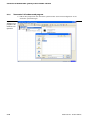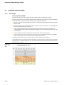
1
BL20 – USER MANUAL ECO GatEway fOr EtherCAT® Sense it! Connect it! Bus it! Solve it! All brand and product names are trademarks or registered trade marks of the owner concerned. Edition 11/2013 © Hans Turck GmbH, Muelheim an der Ruhr All rights reserved, including those of the translation. No part of this manual may be reproduced in any form (printed, photocopy, microfilm or any other process) or processed, duplicated or distributed by means of electronic systems without written permission of Hans Turck GmbH & Co. KG, Muelheim an der Ruhr. Subject to alterations without notice Table of Contents 1 About this manual 1.1 Documentation concept .................................................................................................................................1-2 1.2 Description of symbols used ..........................................................................................................................1-3 1.3 General ............................................................................................................................................................1-4 1.3.1 Prescribed use .........................................................................................................................................................................................1-4 2 BL20-philosophy 2.1 The basic concept ............................................................................................................................................2-2 2.1.1 2.1.2 2.1.3 Flexibility ...................................................................................................................................................................................................2-2 Compactness ...........................................................................................................................................................................................2-2 Easy to handle .........................................................................................................................................................................................2-2 2.2 BL20 components ............................................................................................................................................2-3 2.2.1 2.2.2 2.2.3 2.2.4 2.2.5 2.2.6 2.2.7 2.2.8 2.2.9 2.2.10 Gateways ...................................................................................................................................................................................................2-3 Power distribution modules...............................................................................................................................................................2-4 Electronics modules (standard product line) ...............................................................................................................................2-5 ECO electronics modules.....................................................................................................................................................................2-6 Base modules...........................................................................................................................................................................................2-7 End plate....................................................................................................................................................................................................2-8 End bracket...............................................................................................................................................................................................2-8 Jumpers......................................................................................................................................................................................................2-9 Marking material.....................................................................................................................................................................................2-9 Shield connection (standard product line) ................................................................................................................................ 2-10 3 EtherCAT®-features supported by BL20 3.1 EtherCAT® according to the Modular Device Profile ....................................................................................3-2 3.1.1 3.1.2 3.1.3 3.1.4 3.1.5 EtherCAT®- State Machine...................................................................................................................................................................3-3 SDO-services ............................................................................................................................................................................................3-3 Communication Area............................................................................................................................................................................3-4 Module Object Area (0×6000 - 0×AFFF) ........................................................................................................................................3-7 Device Parameter Area...................................................................................................................................................................... 3-10 3.2 EtherCAT® device description file (ESI-file) ................................................................................................ 3-15 4 Technical features 4.1 Function ...........................................................................................................................................................4-2 4.2 Technical data..................................................................................................................................................4-3 4.2.1 4.2.2 4.2.3 Block diagram..........................................................................................................................................................................................4-4 General technical data of a station ................................................................................................................................................4-4 Technical data for the push-in tension clamp terminals ........................................................................................................4-7 4.3 Connection options at the gateway...............................................................................................................4-8 4.3.1 4.3.2 4.3.3 Power supply ...........................................................................................................................................................................................4-8 Field bus connection via Ethernet-switch .....................................................................................................................................4-9 Service interface connection (mini USB female connector) ................................................................................................ 4-10 4.4 Address assignment ..................................................................................................................................... 4-11 4.5 ESI-file............................................................................................................................................................ 4-12 D301260 1113 - BL20-E-GW-EC i 4.6 Synchronization of the station configuration ............................................................................................ 4-13 4.7 Status indicators/diagnostic messages gateway ....................................................................................... 4-14 4.7.1 4.7.2 4.7.3 4.7.4 Diagnostic messages via LEDs ........................................................................................................................................................4-14 Device Status Object ..........................................................................................................................................................................4-16 Emergency-telegrams........................................................................................................................................................................4-17 I/O-module diagnosis.........................................................................................................................................................................4-19 4.8 Parameters of the modules. ......................................................................................................................... 4-26 4.8.1 4.8.2 4.8.3 4.8.4 Digital input modules ........................................................................................................................................................................4-26 Analog Input Modules .......................................................................................................................................................................4-26 Analog Output Modules....................................................................................................................................................................4-34 technology modules...........................................................................................................................................................................4-39 5 Connection of the EtherCAT®-gateway to the TwinCAT® Soft-PLC 5.1 Application example ...................................................................................................................................... 5-2 5.1.1 5.1.2 5.1.3 5.1.4 5.1.5 5.1.6 5.1.7 5.1.8 5.1.9 General ...................................................................................................................................................................................................... 5-2 Adding a device specific *.xml-file................................................................................................................................................... 5-3 Hardware configuration in the TwinCAT® System Manager.................................................................................................. 5-3 Parameterization of BL20 I/O-modules.......................................................................................................................................... 5-7 Programming the Soft-PLC ................................................................................................................................................................ 5-8 "Connection" of hardware and program.....................................................................................................................................5-10 Process data exchange ......................................................................................................................................................................5-13 Diagnosis in TwinCAT®.......................................................................................................................................................................5-15 Install EtherCAT®-driver .....................................................................................................................................................................5-17 6 Integration of the technology modules 6.1 Integration of the RS232-module.................................................................................................................. 6-2 6.1.1 Data image ............................................................................................................................................................................................... 6-2 6.2 Integration of the RS485/422-module .......................................................................................................... 6-6 6.2.1 Data image ............................................................................................................................................................................................... 6-6 6.3 Integration of the SSI-module ..................................................................................................................... 6-10 6.3.1 Data image .............................................................................................................................................................................................6-10 6.4 Integration of the SWIRE-module BL20-E-1-SWIRE ................................................................................... 6-16 6.4.1 Data image .............................................................................................................................................................................................6-16 6.5 Integration of the Encoder/PWM-module BL20-E-2CNT/2PWM ............................................................... 6-26 6.6 Integration of RFID-modules BL20-2RFID-S/ -A ......................................................................................... 6-26 7 Guidelines for station planning 7.1 Module arrangement...................................................................................................................................... 7-2 7.1.1 7.1.2 7.1.3 Random module arrangement ......................................................................................................................................................... 7-2 Complete planning ............................................................................................................................................................................... 7-2 Maximum system extension.............................................................................................................................................................. 7-3 7.2 Power supply................................................................................................................................................... 7-5 7.2.1 7.2.2 7.2.3 7.2.4 Power supply to the gateway............................................................................................................................................................ 7-5 Module bus refreshing......................................................................................................................................................................... 7-5 Creating potential groups .................................................................................................................................................................. 7-5 C-rail (cross connection)...................................................................................................................................................................... 7-6 ii D301260 1113 - BL20-E-GW-EC 7.2.5 Direct wiring of relay modules ..........................................................................................................................................................7-8 7.3 Protecting the service interface on the gateway ..........................................................................................7-9 7.4 Plugging and pulling electronics modules....................................................................................................7-9 7.5 Extending an existing station.........................................................................................................................7-9 7.6 Firmware download ..................................................................................................................................... 7-10 8 Guidelines for Electrical Installation 8.1 General notes...................................................................................................................................................8-2 8.1.1 8.1.2 8.1.3 8.1.4 General .......................................................................................................................................................................................................8-2 Cable routing ...........................................................................................................................................................................................8-2 Lightning protection.............................................................................................................................................................................8-3 Transmission media...............................................................................................................................................................................8-3 8.2 Potential relationships....................................................................................................................................8-4 8.2.1 General .......................................................................................................................................................................................................8-4 8.3 Electromagnetic compatibility (EMC) ............................................................................................................8-5 8.3.1 8.3.2 8.3.3 8.3.4 8.3.5 Ensuring electromagnetic compatibility .......................................................................................................................................8-5 Grounding of inactive metal components....................................................................................................................................8-5 PE connection..........................................................................................................................................................................................8-5 Earth-free operation ..............................................................................................................................................................................8-5 Mounting rails..........................................................................................................................................................................................8-6 8.4 Shielding of cables ..........................................................................................................................................8-7 8.5 Potential compensation..................................................................................................................................8-8 8.5.1 8.5.2 Switching inductive loads ...................................................................................................................................................................8-8 Protection against Electrostatic Discharge (ESD) .......................................................................................................................8-8 9 BL20-Approvals for Zone 2/Division 2 10 Glossary 11 Index D301260 1113 - BL20-E-GW-EC iii iv D301260 1113 - BL20-E-GW-EC 1 About this manual 1.1 Documentation concept ............................................................................................................................ 1-2 1.2 Description of symbols used .................................................................................................................... 1-3 1.3 General ....................................................................................................................................................... 1-4 1.3.1 Prescribed use ...................................................................................................................................................................................1-4 1.4 List of revisions........................................................................................................................................... 1-5 D301260 1113 - BL20-E-GW-EC 1-1 About this manual 1.1 Documentation concept This manual contains all information about the EtherCAT®-Gateway of the product line BL20-ECO (BL20-E-GW-EC). The following chapter contain a short BL20-description, a description of the field bus system EtherCAT®, exact information about function and structure of the field bus specific BL20-gateway for EtherCAT® as well as all bus specific information concerning the connection to automation devices, the maximum system extension etc. The bus-independent I/O-modules of the BL20-system as well as all bus independent information as mounting, labeling etc. are described in a separate manual. BL20 I/O-modules (TURCK-documentation no.: German D300716; English D300717) In addition to that, the manual contains a short description of the I/O-ASSISTANT, the project planning and configuration software tool for TURCK I/O-systems- 1-2 D301260 1113 - BL20-E-GW-EC Description of symbols used 1.2 Description of symbols used Warning This sign can be found next to all notes that indicate a source of hazards. This can refer to danger to personnel or damage to the system (hardware and software) and to the facility. This sign means for the operator: work with extreme caution. Attention This sign can be found next to all notes that indicate a potential hazard. This can refer to possible danger to personnel and damages to the system (hardware and software) and to the facility. Note This sign can be found next to all general notes that supply important information about one or more operating steps. These specific notes are intended to make operation easier and avoid unnecessary work due to incorrect operation. D301260 1113 - BL20-E-GW-EC 1-3 About this manual 1.3 General Attention Please read this section carefully. Safety aspects cannot be left to chance when dealing with electrical equipment. This manual includes all information necessary for the prescribed use of the BL20-E-GW-EN. It has been specially conceived for personnel with the necessary qualifications. 1.3.1 Prescribed use Appropriate transport, storage, deployment and mounting as well as careful operating and thorough maintenance guarantee the trouble-free and safe operation of these devices. Warning The devices described in this manual must be used only in applications prescribed in this manual or in the respective technical descriptions, and only with certified components and devices from third party manufacturers. 1-4 D301260 1113 - BL20-E-GW-EC List of revisions 1.4 List of revisions In comparison to the previous manual edition, the following changes/ revisions have been made: Table 1-1: List of revisions Chapter Subject 4 5 new changed Connection options at the gateway (page 4-8) x Synchronization of the station configuration (page 4-11) x "Connection" of hardware and program (page 5-10) x Note The publication of this manual renders all previous editions invalid. D301260 1113 - BL20-E-GW-EC 1-5 About this manual 1-6 D301260 1113 - BL20-E-GW-EC 2 BL20-philosophy 2.1 The basic concept ....................................................................................................................................... 2-2 2.1.1 2.1.2 2.1.3 Flexibility .............................................................................................................................................................................................2-2 Compactness .....................................................................................................................................................................................2-2 Easy to handle ...................................................................................................................................................................................2-2 2.2 BL20 components....................................................................................................................................... 2-3 2.2.1 Gateways .............................................................................................................................................................................................2-3 – ECO-gateways ...............................................................................................................................................................................2-3 – Gateways with integrated power supply ............................................................................................................................2-4 – Gateways without integrated power supply .....................................................................................................................2-4 Power distribution modules.........................................................................................................................................................2-4 Electronics modules (standard product line).........................................................................................................................2-5 ECO electronics modules...............................................................................................................................................................2-6 Base modules.....................................................................................................................................................................................2-7 End plate..............................................................................................................................................................................................2-8 End bracket.........................................................................................................................................................................................2-8 Jumpers ...............................................................................................................................................................................................2-9 Marking material ..............................................................................................................................................................................2-9 Shield connection (standard product line) .......................................................................................................................... 2-10 2.2.2 2.2.3 2.2.4 2.2.5 2.2.6 2.2.7 2.2.8 2.2.9 2.2.10 D301260 1113 - BL20-E-GW-EC 2-1 BL20-philosophy 2.1 The basic concept BL20 is a modular I/O system for use in industrial automation. It connects the sensors and actuators in the field with the higher-level master. BL20 offers modules for practically all applications: Digital input and output modules Analog input and output modules Technology modules (counters, RS232 interface...) A complete BL20 station counts as one station on the bus and therefore occupies one fieldbus address in any given fieldbus structure. A BL20 station consists of a gateway, power distribution modules and I/O modules. The connection to the relevant fieldbus is made via the bus-specific gateway, which is responsible for the communication between the BL20 station and the other fieldbus stations. The communication within the BL20 station between the gateway and the individual BL20 modules is regulated via an internal module bus. Note The gateway is the only fieldbus-dependent module on a BL20 station. All other BL20 modules are not dependent on the fieldbus used. 2.1.1 Flexibility All BL20 stations can be planned to accommodate the exact number of channels to suit your needs, because the modules are available with different numbers of channels in block and slice design. A BL20 station can contain modules in any combination, which means it is possible to adapt the system to practically all applications in automated industry. 2.1.2 Compactness The slim design of the BL20 modules (standard gateway 50.4 mm/1.98 inch, ECO gateway 34 mm/1.34 inch, standard slice 12.6 mm/0.49 inch, ECO slice 13 mm/0.51 inch and block 100.8 mm/3.97 inch) and their low overall height favor the installation of this system in confined spaces. 2.1.3 Easy to handle All BL20 modules of the standard line, with the exception of the gateway, consist of a base module and an electronics module. The gateway and the base modules are snapped onto a mounting rail. The electronics modules are plugged onto the appropriate base modules. The base modules of the standard line are designed as terminal blocks. The wiring is secured by tension clamp or screw connection. The electronics modules can be plugged or pulled when the station is being commissioned or for maintenance purposes, without having to disconnect the field wiring from the base modules. The ECO electronics modules combine base module and electronics module in one housing. All BL20ECO modules can be used with the standard products with tension clamp connection technology. 2-2 D301260 1113 - BL20-E-GW-EC BL20 components 2.2 2.2.1 BL20 components Gateways The gateway connects the fieldbus to the I/O modules. It is responsible for handling the entire process data and generates diagnostic information for the higher-level master and the software PACTware with the corresponding TURCK DTMs (I/O-ASSISTANT). ECO-gateways The BL20-ECO gateways enlarge the product portfolio of BL20. They offer an excellent cost/ performance ratio. Further advantages of the BL20- gateways in the ECO-housing: At the moment available for PROFIBUS-DP, DeviceNet™, CANopen, Modbus TCP, EtherNet/IP™ PROFINET and EtherCat® Low required space: width 34 mm/1.34 inch minimal space requirements Integrated power supply Can be combined with all existing standard modules (with tension clamp connection technology) and ECO modules Simple wiring with "Push-in" tension clamp terminals, via DeviceNet™-Open Style Connector or via Ethernet RJ45-connectors Automatic bit rate detection for PROFIBUS-DP and DeviceNet™ Setting of fieldbus address and bus terminating resistor (PROFIBUS-DP, DeviceNet™, CANopen) via DIP-switches Service interface for commissioning with I/O-ASSISTANT 3 (FDT/DTM), without PLC) Figure 2-1: Gateway BL20-E-GW-EC D301260 1113 - BL20-E-GW-EC 2-3 BL20-philosophy Gateways with integrated power supply All standard gateways BL20-GWBR-xxx as well as the BL20-gateways for DPV1 and Ethernet (BL20-GWDPV1, BL20-GW-EN, BL20-GW-EN-IP, BL20-GW-EN-PN, BL20-PG-EN and BL20-PG-EN-IP) offer an integrated power supply unit for feeding the gateway and the connected I/O modules. It is not necessary to supply each individual module with a separate voltage. Gateways without integrated power supply Note The gateways without integrated power supply unit need an additional power supply module (bus refreshing module) which feeds the gateway an the connected I/O modules. 2.2.2 Power distribution modules The power supply for gateways and I/O modules is fed to the power distribution modules; therefore, it is not necessary to supply each individual module with a separate voltage. Figure 2-2: Power distribution module 2-4 D301260 1113 - BL20-E-GW-EC BL20 components 2.2.3 Electronics modules (standard product line) The standard electronics modules contain the I/O-functions of the BL20 modules (power distribution modules, digital and analog input/output modules, and technology modules). They are plugged onto the base modules and are not directly connected to the wiring and can be plugged or pulled when the station is being commissioned or for maintenance purposes, without having to disconnect the field wiring from the base modules. Figure 2-3: Electronics module in slice design (left) and in Block design (right) D301260 1113 - BL20-E-GW-EC 2-5 BL20-philosophy 2.2.4 ECO electronics modules New ECONOMY modules with a high signal density and exceptionally low channel price expand the BL20 I/O bus terminal system. Depending on type, up to 16 digital inputs and outputs can be connected on only 13 mm. This high connection density considerably reduces the mounting width required for typical applications. All advantages at a glance: Space saving thanks to 16 channels on 13 mm/0.51 inch width Cost saving thanks to electronics with integrated connection level High signal density Tool-less connection via "push-in" spring-type terminal technology for simple and fast mounting Flexibility in combining them with standard I/O-modules in tension clamp technology, the standard- and the ECO-gateways. Simple assembly reduces error sources Figure 2-4: ECO I/O-module 2-6 D301260 1113 - BL20-E-GW-EC BL20 components 2.2.5 Base modules The field wiring is connected to the base modules. These are constructed as terminals in block and slice designs and are available in the following variations with either tension clamp or screw connections: 2/3-wire (2-channel), 4-wire (2-channel) and 4x2-/3-wire (4-channel). Figure 2-5: Base module with tension clamp connection Figure 2-6: Base module with screw connection Figure 2-7: Base module in block design D301260 1113 - BL20-E-GW-EC 2-7 BL20-philosophy 2.2.6 End plate An end plate on the right-hand side physically completes the BL20 station. An end bracket mounted into the end plate ensures that the BL20 station remains secure on the mounting rail even when subjected to vibration. Figure 2-8: End plate 2.2.7 End bracket A second end bracket to the left of the gateway is necessary, as well as the one mounted into the end plate to secure the station. Figure 2-9: End bracket Note The end plate and two end brackets are delivered with the gateway. 2-8 D301260 1113 - BL20-E-GW-EC BL20 components 2.2.8 Jumpers Jumpers (QVRs) are used to bridge a connection level of a 4-wire base module. They can be used to connect potentials in relay modules (bridging the relay roots); thus considerably reducing the amount of wiring. Figure 2-10: Jumpers 2.2.9 Marking material Labels: for labeling BL20 electronics modules. Markers: for colored identification of connection levels of BL20 base modules. Dekafix connector markers: for numbering the mounting slots on BL20 base modules. Figure 2-11: Marking material D301260 1113 - BL20-E-GW-EC 2-9 BL20-philosophy 2.2.10 Shield connection (standard product line) If the gateway is wired directly to the fieldbus, it is possible to shield the connection using a special gateway-shielding connection attachment (BS3511/KLBUE4-31.5). Figure 2-12: Shield connection (gateway) 2-10 D301260 1113 - BL20-E-GW-EC 3 EtherCAT®-features supported by BL20 3.1 EtherCAT® according to the Modular Device Profile ............................................................................... 3-2 3.1.1 3.1.2 3.1.3 EtherCAT®- State Machine.............................................................................................................................................................3-3 SDO-services ......................................................................................................................................................................................3-3 Communication Area......................................................................................................................................................................3-4 – Error Register (0×1001) ..............................................................................................................................................................3-5 – Identity Object (0×1018) ...........................................................................................................................................................3-5 – Diagnosis History-Object (0×10F3)........................................................................................................................................3-5 – RxPDO and TxPDO Mapping Objects (0×1600 - 0×17FF and 0×1A00 - 0×1BFF)..................................................3-5 – Sync Manager Communication Type (0×1C00) ................................................................................................................3-6 – Sync Manager PDO Assign (0×1C12 and 0×1C13)...........................................................................................................3-6 – Sync Manager Synchronization (0×1C32 and 0×1C33)..................................................................................................3-6 Module Object Area (0×6000 - 0×AFFF) ..................................................................................................................................3-7 – Input Data Object Area (0×6xxx) ............................................................................................................................................3-7 – Output Data Object Area (0×7xxx0)......................................................................................................................................3-7 – Configuration Data Object Area (0×8xxx)...........................................................................................................................3-7 – Information Data Object Area (0×9xxx)...............................................................................................................................3-9 – Diagnosis Data Object Area(0×Axxx)....................................................................................................................................3-9 Device Parameter Area................................................................................................................................................................ 3-10 – Modular Device Profile (0×F000)......................................................................................................................................... 3-10 – Detected Module Command (0×F002) ............................................................................................................................. 3-11 – Configured Module Ident List (0×F030)............................................................................................................................ 3-12 – Detected Address List (0×F040)........................................................................................................................................... 3-12 – Detected Module Ident List (0×F050)................................................................................................................................ 3-13 – Device Status Object (0×F100)............................................................................................................................................. 3-13 – Device Control Object (0×F200) .......................................................................................................................................... 3-13 – Module List Handling Object (0×2000)............................................................................................................................. 3-14 3.1.4 3.1.5 3.2 EtherCAT® device description file (ESI-file)............................................................................................3-15 D301260 1113 - BL20-E-GW-EC 3-1 EtherCAT®-features supported by BL20 3.1 EtherCAT® according to the Modular Device Profile The EtherCAT®-gateway for BL20-ECO complies to he EtherCAT® Modular Device Profile (MDP) according to EtherCat®-standard ETG 5001. The BL20-ECO gateway for EtherCAT® supports CANopen over EtherCAT® (CoE). Note File Access over EtherCAT® (FoE), Servo Profile over EtherCAT® (SoE) and Ethernet over EtherCAT® (EoE) are not be supported, yet. A Modular Device is a device with physically connectable modules and/or several functional modules. Therefore only one object dictionary exists in the gateway. Each BL20-I/O-module has corresponding entries for inputs, outputs, configuration, information, RxPDOs and TxPDOs. According to the MDP, two defined areas exist in the object dictionary: Communication Area Device Parameter Area The object dictionary is dynamic and always depends on the modules, which are physically connected to the gateway. The object dictionary is created in the device‘s RAM on each power cycle. There is only one object dictionary for the complete station. 3-2 D301260 1113 - BL20-E-GW-EC EtherCAT® according to the Modular Device Profile 3.1.1 EtherCAT®- State Machine Figure 3-1: EtherCAT®State Machine Init Pre-Operational Bootstrap (not supported) Safe-Operational Operational Table 3-1: State Machine 3.1.2 Status Meaning Init Device starts, no SDO and no PDO transfer Pre-Operational SDO transfer, no PDF transfer Safe Operational SDO and PDO transfer The input data are cyclically updated, all slave outputs switch to the safe state, for BL20 "0". Operational SDO and PDO transfer, in- and output data valid SDO-services All SDO-services are integrated according to ETG 1000.5. D301260 1113 - BL20-E-GW-EC 3-3 EtherCAT®-features supported by BL20 3.1.3 Communication Area All mandatory objects in the Communication Area are supported. Some of them are conditional and only appear in the object dictionary, if the modules connected to the gateway need them (e. g: RxPDO Mapping Objects only exist, if output modules are connected to the gateway). Table 3-2: Implemented objects of the Communication Area 3-4 Index Use Description (Value) M = mandatory O = optional C = conditional 0×1000 M Device Type (0×00001389) 0×1001 O Error Register, see page 3-5 0×1008 M Device Name (BL20-E-GW-EC) 0×1009 M Hardware Version 0×100A M Software Version 0×1018 M Identity (Device identification), see page 3-5 0×10F3 O Diagnosis History, see page 3-5 0×1600 - 0×17FF C RxPDO Mapping, see page 3-5 Mandatory if Outputs are connected (see below) 0×1A00 - 0×1BFF) C RxPDO Mapping, see page 3-5 Mandatory if Inputs are connected (see below) 0×1C00 C Sync Manager Communication Type, see page 3-6 0×1C12 C Sync Manager 2 PDO Assignment Mandatory if outputs are connected, see page 3-6 0×1C13 C Sync Manager 3 PDO Assignment Mandatory if inputs are connected, see page 3-6 0×1C32 C Sync Manager 2 Synchronization, see page 3-6 0×1C33 C Sync Manager 3 Synchronization, see page 3-6 D301260 1113 - BL20-E-GW-EC EtherCAT® according to the Modular Device Profile Error Register (0×1001) The Error Register is structured as follows: Table 3-3: Structure of the Error Register Error Register M = mandatory O = optional Meaning Bit 0 M generic error message Bit 1 O Current error Bit 2 O voltage error Bit 3 O temperature error Bit 4 O communication error (overrun, error state) Bit 5 O device profile specific error Bit 6 O reserved Bit 7 O manufacturer specific error Identity Object (0×1018) The Identity Object contains the Vendor ID (Turck 0×0000009C), the Product Code (6827380), the revision- and serial number. This mandatory object with its four sub-objects contains the values found in the Slave Information Interface (SII EEPROM). The object is read only. Diagnosis History-Object (0×10F3) The Diagnosis History object up to 50 diagnostic messages from the gateway and the I/O modules can be stored. Eventually additional explanations for the diagnostic messages of the gateway can be found under Device Status Object (page 4-16).For the I/O modules they can be found in chapter 4, I/O-module diagnosis (page 4-19). RxPDO and TxPDO Mapping Objects (0×1600 - 0×17FF and 0×1A00 - 0×1BFF) Access: RO The PDO Mapping Objects are used to define the structure of the PDOs as described in ETG1000.6 (Application Layer protocol specification). The PDO numbering depends on the module‘s slot-number in the BL20-station and is generated as follows: – Index = 0×1600 + (slot-number -1) for output modules and – Index = 0×1A00 + (slot-number -1) for input modules. Each object consist of one or several sub-objects. Each sub-object represents a module channel and points to input- or output-objects, see Input Data Object Area (0×6xxx) (page 3-7) and Output Data Object Area (0×7xxx0) (page 3-7). Two special RxPDO and TxPDO mapping-objects for each module are created and named based on the module name and direction. For Example: „Mapping RxPDO BL20-E-4AO-U/I“ The corresponding subjects are named based on the channel count. For Example: "Output Mapping Area 2" for channel 2. D301260 1113 - BL20-E-GW-EC 3-5 EtherCAT®-features supported by BL20 Sync Manager Communication Type (0×1C00) This object describes the use of the Sync Manager channels. Table 3-4: Sync Manager Communication Type Sync Manager Channel Description 0 Mailbox Write (EtherCAT® Master view) 1 Mailbox Read (EtherCAT®-Master view) 2 Process output data (EtherCAT®-Master view) 3 Process input data (EtherCAT®-Master view) Sync Manager PDO Assign (0×1C12 and 0×1C13) The PDO Assign objects are used to describe which PDO shall be transmitted with the EtherCAT® input and output data. Access: RO The sub-objects of the Assign objects point to the RxPDO and TxPDO Mapping objects. The mapping for both, for input and output data, is done as follows: 1 The PDOs of all analog and technology modules are mapped at first 2 followed by the PDOs of the digital modules. 3 To get a word boundary for the process data an additional gap PDO may be present after the digital modules. The gap PDO is not visible in the object dictionary. 4 After the process data PDOs, the gateway status PDO and gateway control PDO follow. These special PDOs represent the objects 0×F100 (status, see Device Status Object (0×F100) (page 3-13)) and 0×F200 (control, seeDevice Control Object (0×F200) (page 3-13)). The structure of the process data image thus always depends on the modules connected to the gateway and is constant for that specific station configuration. Example-Mapping An example mapping can be found in chapter 5, Adding a device specific *.xml-file (page 5-3). Sync Manager Synchronization (0×1C32 and 0×1C33) These objects contain the information about the synchronization behavior of the device as described in the ETG1020 (EtherCAT® Protocol Enhancements). Device Status Object (0×F100) (page 3-13) BL20 supports Free Run synchronization, which means, that the EtherCAT®-slave is not running synchronously with EtherCAT®. The slave does not work synchronously with the EtherCAT®-cycle, but has it's own cycle. Access: RO 3-6 D301260 1113 - BL20-E-GW-EC EtherCAT® according to the Modular Device Profile 3.1.4 Module Object Area (0×6000 - 0×AFFF) Table 3-5: Module objects Object Area Index Range Modular Device Input data, siehe page 3-7 0×6xxx Conditional Output data, siehe page 3-7 0×7xxx Conditional Configuration data, see page 3-7 0×8xxx Optional Information data, see page 3-9 0×9xxx Optional Diagnostic data, see page 3-9 0×Axxx Optional Input Data Object Area (0×6xxx) Each module has one input data object with several sub-objects depending on the channel count of the connected module. The input data objects are mapped to TxPDOs which are read cyclically by the Master. There is one TxPDO per module defined. The index of the input data object depends on the module‘s slot-number within the BL20-station: from: Index = 0×6000 + (slot number-1) x 0×0010 → module 1 = 0× 6000, module 2 = 0×6010, module 3 = 0×6020, etc.) The input data area and the TxPDOs of a module only exist if input data of the module is available. Output Data Object Area (0×7xxx0) Each module has one output data object with several sub-objects depending on the channel count of the connected module. The output data objects are mapped in a RxPDO so that it is read cyclically. There is one RxPDO per module defined. The index of the output data object depends on the module‘s slot-number within the BL20-station: from: Index = 0×7000 + (slot number-1) x 0×0010 → module 1 = 0× 7000, module 2 = 0×7010, module 3 = 0×7020, etc.) The output data area and the RxPDOs of a module only exist if output data of the module is available. Configuration Data Object Area (0×8xxx) Each module has one configuration data object with several sub-objects depending on the channel count of the connected module. The index of the configuration data object depends on the module‘s slot-number within the BL20station: Index = 0×8000 + (slot number--1) x 0×0010 → module 1 = 0× 8000, module 2 = 0×8010, module 3 = 0×8020, etc.) Some sub-indices contain module-parameters. The EtherCAT®-Master can write them to the gateway or the modules during the state transition from PRE-OP to SAFE-OP (see EtherCAT®- State Machine (page 3-3)). D301260 1113 - BL20-E-GW-EC 3-7 EtherCAT®-features supported by BL20 The module-parameters are defined in the EtherCAT® device description file (ESI-file) (page 3-15). Table 3-6: Konfigurationsdaten Data Type Use Details Subindex Name 0×01 Module address UNSIGNED 16 C 0×02 Type string VISIBLE STRING O not supported 0×03 Name string VISIBLE STRING O Contains the name of the module 0×04 Device type UNSIGNED 32 C/M Mandatory for modules which support CoE or a vendor specific profile (BL20). 0×05 Vendor ID UNSIGNED 32 C not supported 0×06 Product code UNSIGNED 32 C Contains the product code. Mandatory if supported. 0×07 Revision number UNSIGNED 32 C Contains the revision no. Mandatory if supported. 0×08 Serial number UNSIGNED 32 C not supported 0×09 Module PDO group UNSIGNED 16 C Used for modular devices which have a different mapping order. Defines the mapping order. For BL20 the following modules groups are defined: 0 = gateway 1 = analog and technology modules 2 = digital modules 0×0A Module ident UNSIGNED 32 Used to identify each module in the device. 0×0B Slot UNSIGNED 16 Defines the position of the module within the device. 0×0C Slot group UNSIGNED 16 not supported M = mandat. O = optional C = conditional 0×0D to reserved 0×1D 3-8 0×1E Network segment address OCTETSTRING[6] not supported 0×1F Network port UNSIGNED 32 not supported D301260 1113 - BL20-E-GW-EC EtherCAT® according to the Modular Device Profile Table 3-6: Konfigurationsdaten Subindex Name 0×20 to 0×FF Vendor / profile specific Data Type Use Details M = mandat. O = optional C = conditional O Parameters of the modules. Depending on the modules connected to the gateway. If a module supports parameterization, then the parameters start at sub-index 0×20 in object 0×8000. Information Data Object Area (0×9xxx) Each module has one information data object. The index of the information data object depends on the module‘s slot-number within the BL20station: from: Index = 0×9000 + (slot number--1) x 0×0010 → module 1 = 0× 9000, module 2 = 0×9010, module 3 = 0×9020, etc.) This object has the same structure as Configuration Data objects and supports the same sub-indexes except for the ones for the parameters. (0×20 to 0×FF). Diagnosis Data Object Area(0×Axxx) Each module in a BL20-station has one diagnosis data object. The index of the diagnosis data object depends on the module‘s slot-number within the BL20-station: from: Index = 0×A000 + (slot number--1) x 0×0010 → module 1 = 0×A000, module 2 = 0×A010, module 3 = 0×A020, etc.) Each channel of a module has one sub-object in the diagnosis data area starting with sub-index 1. Here, only the last diagnosis message of a channel can be read. Note Older diagnosis messages can be read from the Diagnosis History Object (see Diagnosis History-Object (0×10F3) (page 3-5)). This objects and the corresponding sub-objects only exists if the corresponding module supports diagnosis data. D301260 1113 - BL20-E-GW-EC 3-9 EtherCAT®-features supported by BL20 3.1.5 Device Parameter Area The device parameter area contains all parameters which belong to the EtherCAT® device (gateway). The BL20 gateway supports the mandatory objects of the Modular Device Profile as well as the objects 0×F100 and 0×F200 which are mapped into the process data. Table 3-7: Device parameter area for BL20 Index Name 0×F000 Modular Device Profile, see page 3-10. 0×F002 Detected Module Command Scan of the module bus for the actually connected modules after a possible module exchange, see page 3-11. 0×F030 Configured Module Ident List List of the configured modules, see page 3-12 0×F040 Detected Address List List of the slot-numbers of the I/O modules at the gateway. An empty slot is shown as "0" page 3-12. 0×F050 Detected Module Ident List List of the detected modules, see page 3-13 0×F100 Device status (T×PDO mappable), see page 3-13 0×F200 Device status (T×PDO mappable), see page 3-13 0×2000 Module List Handling Object, see page 3-14 Modular Device Profile (0×F000) The modular device profile object contains all information to interpret the objects of the object area of the modules. Access: RO not PDO-mappable Table 3-8: Modular Device Profile, 3-10 Subindex Name Data Type 0 Number of entries UNSIGNED8 Padding UNSIGNED8 1 Index distance 2 Maximum number of modules Use Details M = mandat. O = optional C = conditional M BL20 = 5 UNSIGNED16 M Maximum number of objects per module BL20 = 10 UNSIGNED16 M BL20 = 72 modules D301260 1113 - BL20-E-GW-EC EtherCAT® according to the Modular Device Profile Table 3-8: Modular Device Profile, Subindex Name Data Type Use Details 3 General configuration UNSIGNED32 C Available sub-indices in General configuration objects 0×8xx0, see also Configuration Data Object Area (0×8xxx) (page 3-7)) Bit 0 = 1 → 0×8xx0:sub-index 1 Bit 1 = 1 → 0×8xx0:sub-index 2 etc. 4 General information UNSIGNED32 C Available sub-indices in General information objects 0×9xx0, see also Information Data Object Area (0×9xxx) (page 3-9)) Bit 0 = 1 → 0×9xx0:sub-index 1 Bit 1 = 1 → 0×9xx0:sub-index 2 etc. 5 Module PDO group of device UNSIGNED16 C BL20 = 0 M = mandat. O = optional C = conditional Detected Module Command (0×F002) This object allows a directed scanning of the module bus in case of a necessary module exchange. The object has 3 sub-indices: Table 3-9: Detected Module Command Sub-index Meaning 0×F002:01 Command 0×F002:02 Status 0×F002:03 Response Executing a Detected Module Command 1 Writing any value to sub-index 0×F002:01 activates the scan of the module bus. 2 The scan was successful, if sub-index 0×F002:03 (Response) contains "0" after the scan. 3 If new or missing modules are detected, the list of module IDs Detected Module Ident List (0×F050)as well as the list of slot-numbers Detected Address List (0×F040) are updated. 4 All other objects remain static and are only updated following a power-reset. D301260 1113 - BL20-E-GW-EC 3-11 EtherCAT®-features supported by BL20 Configured Module Ident List (0×F030) Contains the module ident numbers of the modules configured in the master for the BL20-station. The EtherCAT® Master downloads the module ident list to the BL20-gateway and the gateway compares this list to the expected module configuration. In case of a difference between this list and the list in object 0×F050, see Detected Module Ident List (0×F050) (page 3-13), the write request on the specific sub-object will be denied with SDO Abort Code 0×08000020. Table 3-10: Configured Module Ident List Sub-index Data Type Description 1 UNSIGNED32 Module ident number of the module configured at slot 1 after the gateway. 2 UNSIGNED32 Module ident number of the module configured at slot 2 after the gateway. … 72 … UNSIGNED32 Module ident number of the module configured at slot 72 after the gateway. Detected Address List (0×F040) This object contains a list of slot-numbers (addresses) of the modules actually connected to the gateway during a gateway-restart or if a Detected Module Command (0×F002)has been executed. An empty slot is shown as "0". Table 3-11: Detected Address List Sub-index Data Type Description 1 UNSIGNED16 Address (slot-no.) number of the module detected at slot 1 after the gateway. 2 UNSIGNED16 Address (slot-no.) number of the module detected at slot 2 after the gateway. … 72 3-12 … UNSIGNED16 Address (slot-no.) number of the module detected at slot 72 after the gateway. D301260 1113 - BL20-E-GW-EC EtherCAT® according to the Modular Device Profile Detected Module Ident List (0×F050) Contains the module ident numbers of the modules physically present in the BL20-station. Table 3-12: Detected Module Ident List Sub-index Data Type Description 1 UNSIGNED32 Module ident number of the module detected at slot 1 after the gateway. 2 UNSIGNED32 Module ident number of the module detected at slot 2 after the gateway. … … 72 UNSIGNED32 Module ident number of the module detected at slot 72 after the gateway. Device Status Object (0×F100) This object contains the gateway status word. It is mapped in a TxPDO and can thus be read cyclically by the EtherCAT® Master. Byte Bit 7 Bit 6 Bit 5 0 Under voltage UL 1 Module bus failure Force mode active Bit 4 Bit 3 Bit 2 Bit 1 I/O configuration changed - Module bus error Master configuration error - - Diagnosis message available Bit 0 Summarized module diagnosis Under Over voltage Usys voltage Usys Further information can be found in section Device Status Object (page 4-16). Device Control Object (0×F200) Not supported, yet. Reserved for future use. D301260 1113 - BL20-E-GW-EC 3-13 EtherCAT®-features supported by BL20 Module List Handling Object (0×2000) This object serves for manual synchronization of the two module lists in the gateway (Configured Module Ident List (0×F030) and Detected Module Ident List (0×F050)). Sub-index 01: Writing any value to this sub-index activates the copying of theDetected Module Ident List (0×F050) into the Configured Module Ident List (0×F030). Sub-index 02: Writing any value to this sub-index activates the deleting of the Configured Module Ident List (0×F030). Note Please observe, that a power-reset has to be executed after writing to the Module Handling object. Changes will not be accepted without a power-reset. 3-14 D301260 1113 - BL20-E-GW-EC EtherCAT® device description file (ESI-file) 3.2 EtherCAT® device description file (ESI-file) EtherCAT® uses an *.xml-file, the EtherCAT® Slave Information (ESI) to represent a device. This file can be imported to the EtherCAT® PLC program. D301260 1113 - BL20-E-GW-EC 3-15 EtherCAT®-features supported by BL20 3-16 D301260 1113 - BL20-E-GW-EC 4 Technical features 4.1 Function ...................................................................................................................................................... 4-2 4.2 Technical data............................................................................................................................................. 4-3 4.2.1 4.2.2 4.2.3 Block diagram....................................................................................................................................................................................4-4 General technical data of a station ..........................................................................................................................................4-4 – Approvals and tests.....................................................................................................................................................................4-7 Technical data for the push-in tension clamp terminals ..................................................................................................4-7 4.3 Connection options at the gateway.......................................................................................................... 4-8 4.3.1 4.3.2 4.3.3 Power supply .....................................................................................................................................................................................4-8 Field bus connection via Ethernet-switch...............................................................................................................................4-9 Service interface connection (mini USB female connector) .......................................................................................... 4-10 4.4 Address assignment.................................................................................................................................4-11 4.5 ESI-file .......................................................................................................................................................4-11 4.6 Synchronization of the station configuration .......................................................................................4-11 4.6.1 4.6.2 Synchronization via software using object access............................................................................................................ 4-11 Synchronization via hardware using the CFG-switch ...................................................................................................... 4-11 4.7 Status indicators/diagnostic messages gateway ..................................................................................4-13 4.7.1 4.7.4 Diagnostic messages via LEDs.................................................................................................................................................. 4-13 – LED-displays................................................................................................................................................................................ 4-13 Device Status Object.................................................................................................................................................................... 4-15 Emergency-telegrams ................................................................................................................................................................. 4-16 – Structure of the Emergency-frames ................................................................................................................................... 4-16 I/O-module diagnosis .................................................................................................................................................................. 4-18 4.8 Parameters of the modules. ....................................................................................................................4-25 4.8.1 4.8.2 4.8.3 4.8.4 Digital input modules.................................................................................................................................................................. 4-25 Analog input modules................................................................................................................................................................. 4-25 Analog output modules.............................................................................................................................................................. 4-33 Technology modules ................................................................................................................................................................... 4-38 4.7.2 4.7.3 D301260 1113 - BL20-E-GW-EC 4-1 Technical features 4.1 Function BL20-gateways for EtherCAT® are used to connect BL20 IO modules to an EtherCAT®-network. The gateway handles the entire process data exchange between the I/O-level and the fieldbus and generates diagnostic information for higher-level nodes and the software tool I/O-ASSISTANT. 4-2 D301260 1113 - BL20-E-GW-EC Technical data 4.2 Technical data Figure 4-1: Front view A LEDs for BL20 module bus B service interface C 2 LEDs for the EtherCAT® communication D EtherNet-switch with EtherNetLEDs E terminals for field supply F terminals for system supply GW A IOs B SERVICE RUN C ETH2 ETH1 Slide top cover for configuration and service D ! Unlock end-bracket before dismounting ERR UL E GNDL USYS F GNDSYS D301260 1113 - BL20-E-GW-EC 4-3 Technical features 4.2.1 Block diagram Figure 4-2: Block diagram BL20-E-GW-EC Service USB Module bus CPU Switch 5V 24 V Eth1 Usys Eth2 UL Gateway 4.2.2 General technical data of a station Attention The auxiliary power supply must comply with the stipulations of SELV (Safety Extra Low Voltage) according to IEC 364-4-41. Table 4-1: General technical data of a station Supply voltage/auxiliary voltage Usys (nominal value) (provision for other modules) 24 VDC Isys (on maximum system extension → see page 7-3) approx. 600 mA UL nominal value 24 VDC ILmax (maximum field supply current) 8A permissible range according to EN 61131-2 (18 to 30 V DC) Residual ripple according to EN 61 131-2 Isolation voltage (UL to USYS) 500 Veff Voltage anomalies according to EN 61 131-2 IMB (supply of module bus nodes) 700 mA Connection technology Push-in tension clamp terminals, LSF from Weidmueller Physical interfaces Field bus 4-4 Ethernet D301260 1113 - BL20-E-GW-EC Technical data Transmission rate 100 Mbps Passive fiber-optic-adapters can be connected current consumption max. 100 mA Fieldbus connection technology RJ45-female connector, RJ45-male connector Fieldbus shielding connection via Ethernet cable service interface mini USB Address setting not necessary for EtherCAT®, address switches without function Isolation voltages UBL(Usys against service interface) - UETH (supply voltage against Ethernet) 500 V AC UUSB (supply voltage against USB) - UETHETH (ETH1 against ETH2) 500 V AC Ambient conditions Ambient temperature tAmbient 0…+55 °C tStore - 25…+85 °C Relative humidity according to EN 61131-2/EN 50178 5 to 95 % (indoor), Level RH-2, no condensation (storage at 45 °C, no function test) Climatic tests according to IEC 61131-2 Vibration resistance 10 to 57 Hz constant amplitude 0.075 mm, 1 g yes 57 to 150 Hz 57 to 150 Hz, constant acceleration 1 g yes Mode of vibration Frequency sweeps with a change in speed of 1 Octave/min Period of oscillation 20 frequency sweeps per axis of coordinate Shock resistant according to IEC 68-2-27 18 shocks, sinusoidal half-wave 15 g peak value/ 11 ms, in each case in ± direction per space coordinate Resistance to repetitive shock according to IEC 68-2-29 1 000 shocks, half-sinus 25 g peak value/6 ms, in each case in ± direction per space coordinate D301260 1113 - BL20-E-GW-EC 4-5 Technical features Drop and topple Height of fall (weight < 10 kg) 1.0 m Height of fall (weight 10 to 40 kg) 0.5 m Test runs 7 Device with packaging, electrically tested printed-circuit board. Electromagnetic compatibility (EMC) according to EN 50 082-2 (Industry) Static electricity according to EN 61 000-4-2 Discharge through air (direct) 8 kV Relay discharge (indirect) 4 kV Electromagnetic HF fields according to EN 61 000-4-3 and ENV 50 204 10 V/m Conducted interferences induced by HF fields according to EN 61 000-4-6 10 V Fast transients (Burst) according to EN 61 000-4-4 Emitted interference according to EN 50 081-2 (industry) according to EN 55 011 Class A, Group 1 Note This device can cause radio disturbances in residential areas and in small industrial areas (residential, business and trading). In this case, the operator can be required to take appropriate measures to suppress the disturbance at his own cost. 4-6 D301260 1113 - BL20-E-GW-EC Technical data Approvals and tests Table 4-2: Approvals and tests for a BL20 station Designation Approvals UL CSA in preparation Tests (EN 61131-2) 4.2.3 Cold DIN IEC 68-2-1, Temperature -25 °C/185 °F, duration 96 h; device not in use Dry heat DIN IEC 68-2-2, Temperature +85 °C/185 °F, duration 96 h; device not in use Damp heat, cyclic DIN IEC 68-2-30, temperature +55 °C/131 °F, duration 2 cycles every 12 h; device in use Operational life MTBF 120 000 h Pollution severity according to IEC 664 (EN 61 131-2) 2 Protection to IEC 529/EN 60529 IP20 Technical data for the push-in tension clamp terminals Designation Table 4-3: Technical data Protection class Push-in tension clamp terminals Insulation stripping length Max. wire range IP20 8 mm + 1/0.32 inch + 0,039 0.14 to 1.5 mm2/0.0002 to 0.0023 inch2/ 26 to 16 AWG Crimpable wire "e” solid core H 07V-U 0.14 to 1.5 mm2/0.0002 to 0.0023 inch2/ 26 to 16 AWG "f” flexible core H 07V-K 0,5 to 1,5 mm2/0.0008 to 0.0023 inch2/ 25 to 16 AWG "f” with ferrules according to DIN 46 228/1 (ferrules crimped gas-tight) 0.25 to 1.5 mm2/0.0004 to 0.0023 inch2/ 30 to 16 AWG D301260 1113 - BL20-E-GW-EC 4-7 Technical features 4.3 Connection options at the gateway ETH2 EtherCAT OUT ETH1 EtherCAT IN + UL GNDL ! Unlock end-bracket before dismounting Figure 4-3: Connection options at the gateway Slide top cover for configuration and service The fieldbus connection is realized via an integrated RJ45-Ethernet-switch, the connection of the power supply via push-in tension clamps. Field supply USYS GNDSYS 4.3.1 – + – System supply Power supply The BL20-E-GW-EC provides an integrated power supply unit and push-in tension clamps for: field supply (UL, GNDL) and system supply (USYS, GNDSYS) Note The gateway only changes to data exchange if both voltages are connected. 4-8 D301260 1113 - BL20-E-GW-EC Connection options at the gateway 4.3.2 Field bus connection via Ethernet-switch The BL20-ECO-gateways for Ethernet provide an integrated RJ45-Ethernet-switch. Figure 4-4: RJ45 female connector 87654321 Table 4-4: RS485, pin assignment 1 = TX + 2 = TX – 3 = RX + 4 = n.c. 5 = n.c. 6 = RX – 7 = n.c. 8 = n.c. Pin-no. Signal Color 1 TX+ Transmit data + YE yellow 2 TX– Transmit data - OG orange 3 RX+ Receive data + WH white 4 not connected - - 5 not connected - - 6 RX– BU blue 7 not connected - - 8 not connected - - Receive data – Ethernet Port properties: Data rate: 100 Mbps Ethernet LED-states See LEDs LNK- and ACT in section Diagnostic messages via LEDs (page 4-13). D301260 1113 - BL20-E-GW-EC 4-9 Technical features 4.3.3 Service interface connection (mini USB female connector) The service interface is used to connect the gateway to the project planning and diagnostic software I/O-ASSISTANT. The service interface is designed as a 5 pole mini-USB-connection. In order to connect the gateway’s service-interface to the PC, a commercial cable with mini USB connector (commonly used for e.g. digital cameras) is necessary. Figure 4-5: Mini-USD female connector at the gateway GW IOs SERVICE RUN ERR 4-10 D301260 1113 - BL20-E-GW-EC Address assignment 4.4 Address assignment EtherCAT® provides automatic addressing of the network nodes by the EtherCAT®-master. Hardware address assignment at the BL20-gateway is not necessary. 4.5 ESI-file The actual ESI-file (ESI = EtherCAT® Slave Information) for gateway BL20-E-GW-EC (BL20-E-GW-EC.xml) can be downloaded from our homepage www.turck.de . Concerning the usage of the *.xml-file in TwinCAT®, please read Adding a device specific *.xml-file (page 5-3). 4.6 Synchronization of the station configuration In EtherCAT®, saving the current configuration (Configured Module Ident List (0×F030)) of the BL20-station as actual configuration (Detected Module Ident List (0×F050)) to the non-volatile memory of the gateway is done either via object access in the software (see Module List Handling Object (0×2000) (page 3-14)) or via the DIP-switch no. 1 at the gateway. 4.6.1 Synchronization via software using object access See Module List Handling Object (0×2000) (page 3-14). 4.6.2 Synchronization via hardware using the CFG-switch Thh DIP-switches are located under the gateway’s upper label. For setting the DIP-switch pull out the label. Figure 4-6: Front view with label: Front view without label: gatewayfront view A DIP-switch (CFG, no. 1) for storing the station configuration GW IOs SERVICE NO 10 9 8 7 6 5 4 3 2 1 A RUN ERR D301260 1113 - BL20-E-GW-EC 4-11 Technical features Switching to ON starts the storage of the Current Configuration as the Required Configuration (Reference configuration). Procedure: Switching the DIP-switch no. 1 to ON → Starting of storage process → LED IOs flashes green (1 Hz) → LED IOs shortly lits up orange → storage process active → set back the DIP-switch → storage process terminated successfully, if the LEDs IOs and GW are constant green. Note If the DIP-switch is not set back, the gateway will continuously restart the storage process. Only setting the switch back will terminate this process. 4-12 D301260 1113 - BL20-E-GW-EC Status indicators/diagnostic messages gateway 4.7 Status indicators/diagnostic messages gateway Diagnostics messages are indicated in two different ways: via the LEDs via the software of the respective field bus master (for example PLC) 4.7.1 Diagnostic messages via LEDs Every BL20 gateway displays the following statuses via LEDs: 2 LEDs for the module bus communication (module bus-LEDs): GW and IOs 2 LEDs for the EtherCAT® communication (field bus-LEDs): RUN and ERR 4 LEDs for the EtherNet-Link: LNK and ACT (at both female connectors of the EtherNet-switch). LED-displays Table 4-5: LED-displays LED Status Meaning GW OFF No power supply of the CPU. Check the system power supply at the gateway. green Firmware active, gateway ready - green flashing, 1 Hz Firmware not active If LED “IOs“ red, then firmware-download necessary green flashing, 4 Hz Firmware active. gateway-hardware-failure Replace the gateway. red hardware-failure, no communication possible Replace the gateway. red/green flashing, 4 Hz WINK WINK-Command active (serves for the identification of the device) OFF No power supply of the CPU. Check the system power supply at the gateway. green Module bus is running if LED MS green Configured modules match plugged modules green flashing, 1 Hz Station is in the Force Mode of I/O-ASSISTANT. Deactivate the Force Mode of the I/O-ASSISTANT red Hardware error Replace the gateway. red flashing, 1 Hz The actual and the configured module list do not match, no communication Check the physical station for pulled or new but not planned modules. red flashing, 4 Hz No communication via the module bus. At least one module has to be plugged and has to be able to communicate with the gateway. IOs D301260 1113 - BL20-E-GW-EC Remedy 4-13 Technical features Table 4-5: LED-displays LED Status Meaning Remedy IOs red/green flashing, 1 Hz The current and configured module list do not match but the data exchange proceeds as normal. Check the physical station for pulled or new but not planned modules. RUN OFF The device is in state INITIAL- see EtherCAT®- State Machine (page IZATION 3-3) green, flashing 200 ms on/ 200 ms off (Blinking) The device is in state PREOPERATIONAL green, flashing 200 ms on/ 1000 ms off (Single Flash) The device is in state SAFEOPERATIONAL green The device is in state OPERATIONAL OFF Process data exchange red Critical communication error Execute a power-rest, eventually the or controller error occurred device has to be changed. red, flashing: 200 ms on/ 200 ms off (Blinking) Invalid configuration red, flashing: 200 ms on/ 1000 ms off (Single Flash) local error The device switches to the SAFE-OPERATIONAL state due to an internal error (see EtherCAT®- State Machine (page 3-3)). green Link established,100 Mbps green, flashing Data exchange (EthernetTraffic 100 Mbps) OFF no link ERR LNK/ ACT (left LED) 4-14 Check if the hardware configuration of your device matches the configured Check the Ethernet-connection. D301260 1113 - BL20-E-GW-EC Status indicators/diagnostic messages gateway 4.7.2 Device Status Object The gateway sends a gateway Status Word. This can be tread from the Device Status object, object 0×F100. It is mapped in a TxPDO and can thus be read cyclically by the EtherCAT® Master. Byte Bit 7 Table 4-6: Status Word bit assignment Meaning Bit 6 Bit 5 Bit 4 Bit 3 Bit 2 Bit 1 0 Under voltage UL - - - I/O Module bus configuration error changed 1 Module bus failure Force mode active - - Master configuration error - Bit 0 Diagnosis message available Summarized module diagnosis Over Under voltage Usys voltage Usys Diagnostic message Meaning Summarized module diagnosis Diagnosis message available At least one module has a diagnostic message. Diagnosis message available New diagnosis message available. The Diagnosis History Object contains a new message. Module bus error module bus error No modules connected or the communication to the modules is disturbed. I/O configuration changed Station configuration changed The Configured Module Ident List (0×F030) (page 3-12) differs from the Detected Module Ident List (0×F050) (page 3-13) in the gateway. Process data can still be exchanged with the module bus stations which are at present connected to the module bus. Undervoltage UL Undervoltage at UL The field supply is not within the permissible range. Undervoltage Usys Undervoltage Usys The system supply is not within the permissible range. Overvoltage Usys Undervoltage Usys The system supply is not within the permissible range. Master configuration error Master configuration error The Configured Module Ident List (0×F030) (page 3-12) differs in such a manner from the Detected Module Ident List (0×F050) (page 3-13), that no process data can be exchanged with the module bus stations which are at present connected to the module bus. The gateway changes to the PRE-OPERATIONAL state (see also EtherCAT®- State Machine (page 3-3). D301260 1113 - BL20-E-GW-EC 4-15 Technical features Table 4-6: Status Word bit assignment Meaning 4.7.3 Diagnostic message Meaning Force mode active I/O-ASSISTANT Force Mode active The force mode has been activated via the service interface (by I/O-ASSISTANT). This separates the fieldbus master from the outputs of the module bus stations. No process data exchange is taking place from the fieldbus master to the output modules. Parameterization of the modules through the master is not possible as well. Module bus failure module bus breakdown The module bus is not running or can not be started. Emergency-telegrams Structure of the Emergency-frames In the event of a communication error, not only the Emergency Error Code but also the Error register (see also Error Register (0×1001) (page 3-5)) and additional information will be transmitted, so that the error can be more precisely identified. byte Data content Table 4-7: Emergencyframe contents 1 Error Code Values, see Table 4-7:) 2 ErrorRegister 3 4 slot-no. 5 6 Value Meaning Error Code 0×0000 Error-reset/no error 0×FF00 Device specific error 0×00 no error 0×81 manufacturer specific error/generic error (see also Error Register (0×1001) (page 3-5)) 0×0000 Gateway sends an Emergency-frame 0×0100 to 0×0148 slot-no. of the module which sends an emergency-frame. 0×0000 to 0×0020 Number of the channel at which a diagnosis is present. slot-no. channel-no. 7 channel-no. or reserved Gateway Status information Data content Error Register 4-16 0 D301260 1113 - BL20-E-GW-EC Status indicators/diagnostic messages gateway Table 4-7: Emergencyframe contents Data content Value Meaning Gateway status-information 0×0100 Summarized module diagnosis 0×0101 Diagnosis message available 0×0102 Module bus error 0×0103 I/O configuration changed 0×0107 Undervoltage UL 0×0108 Overvoltage Usys 0×0109 Undervoltage Usys 0×010B Master configuration error 0×010E Force mode active 0×010F Module bus failure 0×0110 no valid I/O configuration stored 0×0111 missing UL inhibits I/O configuration storage 0×0112 undervoltage Usys inhibits I/O configuration storage D301260 1113 - BL20-E-GW-EC Content from Device Status Object (page 4-15) 4-17 Technical features 4.7.4 I/O-module diagnosis BL20-BR-24VDC-D Table 4-8: BL20-BR24VDC-D Diagnosis Byte n Bit Diagnostic 0 Module bus voltage warning 1 reserved 2 Undervoltage field supply 3 reserved BL20-PF-24VDC Table 4-9: BL20-PF-24VDC Diagnosis Byte n Bit Diagnostic 0 reserved 1 reserved 2 Undervoltage field supply reserved BL20-PF-120/230VAC-D Table 4-10: BL20-PF-120/ 230VAC-D Diagnosis Byte n Bit Diagnostic 0 reserved 1 reserved 2 Undervoltage field supply reserved 4-18 D301260 1113 - BL20-E-GW-EC Status indicators/diagnostic messages gateway BL20-4DI-NAMUR Table 4-11: BL20-4DINAMUR Diagnostic byte n Bit Diagnostic 0 short circuit sensor 1 1 open circuit sensor 1 2 short circuit sensor 2 3 open circuit sensor 2 4 short circuit sensor 3 5 open circuit sensor 3 6 short circuit sensor 4 7 open circuit sensor 4 BL20-1AI-I(0/4...20MA) Table 4-12: BL20-1AI-I(0/ 4...20MA) Diagnosis Byte n (channel 1) Bit Diagnostic 0 Measurement value range error 1 open circuit Only in the measurement range 4 to 20 mA BL20-2AI-I(0/4...20MA) Table 4-13: BL20-2AI-I(0/ 4...20MA) Diagnosis Byte n (channel 1) n+1 (channel 2) Bit Diagnostic 0 Measurement value range error 1 open circuit 0 Measurement value range error 1 open circuit Only in the measurement range 4 to 20 mA Only in the measurement range 4 to 20 mA BL20-1AI-U(-10/0...+10VDC) Table 4-14: BL20-1AI-U (-10/ 0...+10VDC) Diagnosis Byte n (channel 1) D301260 1113 - BL20-E-GW-EC Bit Diagnostic 0 Measurement value range error Only in the measurement range 4 to 20 mA 4-19 Technical features BL20-2AI-U(-10/0...+10VDC) Table 4-15: BL20-2AI-U (-10/ 0...+10VDC) Diagnosis Byte Bit Diagnostic n (channel 1) 0 measurement value range error A n (channel 2) 0 measurement value range error A BL20-2AI-PT/NI-2/3 Table 4-16: BL20-2AI-PT/NI2/3 Diagnosis Byte n (channel 1) Bit Diagnostic 0 Measurement value range error (Underflow diagnostics in temperature measurement ranges only) 1 open circuit 2 Short circuit (in temperature measurement ranges only) 3 to 7 reserved threshold: 1% of the positive measurement range end value threshold: 5 Ω (loop resistance) BL20-2AI-THERMO-PI Table 4-17: BL20-2AITHERMO-PI Diagnosis Byte n 4-20 Bit Diagnostic 0 Measurement value range error 1 open circuit (in temperature measurement ranges only) 2 to 7 reserved threshold: 1% of the positive measurement range end value D301260 1113 - BL20-E-GW-EC Status indicators/diagnostic messages gateway BL20-4AI-U/I Table 4-18: BL20-4AI-U/I Diagnosis Byte n (channel 0) to n + 3 (channel 3) Bit Diagnostic 0 Measurement value range error threshold: 1% of the positive measurement range end value, underflow diagnostics only in value range 1 open circuit threshold: 3 mA (only in value range 4...20 mA) 2 to 7 reserved BL20-E-8AI-U/I-4AI-PT/NI Table 4-19: BL20-E-8AI-U/I4AI-PT/NI Diagnosis Byte n Bit Diagnostic 0 Measurement value range error (Out of Range, OoR) Thresholds, see IO-manual D300717 1 Wire Break (WB) 2 Short circuit (SC) In 3-wire measurement with PT100- sensor and at temperatures of below -177°C, the module can not distinguish between short-circuit and wire break. In this case a "shortcircuit"- diagnostic is generated. 3 Overflow/Underflow (OUFL) 4-6 reserved 7 hardware failure BL20-2DO-24VDC-0.5A-P Table 4-20: BL20-2DO24VDC-0.5A-P Diagnosis Byte n D301260 1113 - BL20-E-GW-EC Bit Diagnostic 0 overcurrent (short-circuit channel 1) 1 overcurrent (short-circuit channel 2) 4-21 Technical features BL20-2DO-24VDC-0.5A-N Table 4-21: BL20-2DO24VDC-0.5A-N Diagnosis Byte n Bit Diagnostic 0 overcurrent (short-circuit channel 1) 1 overcurrent (short-circuit channel 2) BL20-2DO-24VDC-2A-P Table 4-22: BL20-2DO24VDC-2A-P Diagnosis Byte n Bit Diagnostic 0 overcurrent (short-circuit channel 1) 1 overcurrent (short-circuit channel 2) BL20-4DO-24VDC-0.5A-P Table 4-23: BL20-4DO24VDC-0.5A-P Diagnosis Byte n Bit Diagnostic 0 overcurrent /short-circuit (1 ch. min) BL20-16DO-24VDC-0.5A-P Table 4-24: BL20-16DO24VDC-0.5A-P Diagnosis Byte n 4-22 Bit Diagnostic 0 Overcurrent (short-circuit channel 1-4) 1 Overcurrent (short-circuit channel 5-8) 2 Overcurrent (short-circuit channel 9-12) 3 Overcurrent (short-circuit channel 13-16) D301260 1113 - BL20-E-GW-EC Status indicators/diagnostic messages gateway BL20-32DO-24VDC-0.5A-P Table 4-25: BL20-32DO24VDC-0.5A-P Diagnosis Byte n Bit Diagnostic 0 Overcurrent (short-circuit channel 1-4) 1 Overcurrent (short-circuit channel 5-8) 2 Overcurrent (short-circuit channel 9-12) 3 Overcurrent (short-circuit channel 13-16) 4 Overcurrent (short-circuit channel 17-20) 5 Overcurrent (short-circuit channel 21-24) 6 Overcurrent (short-circuit channel 25-28) 7 Overcurrent (short-circuit channel 29-32) BL20-E-4AO-U/I Table 4-26: BL20-E-4AO-U/I Diagnosis Byte n Bit Diagnostic 0 Measurement value range error (Out of Range, OoR) 1+2 reserved 3 Overflow/Underflow, OUFL (Overflow/Underflow, OUFL) 4-6 reserved 7 hardware failure Thresholds, see IO-manual D300717 BL20-1RS232 Table 4-27: BL20-1RS232 Diagnostic byte n D301260 1113 - BL20-E-GW-EC Bit Diagnostic 0 parameterization error 1 hardware failure 3 data flow control error 4 frame error 5 buffer overflow 4-23 Technical features BL20-1RS485/422 Table 4-28: BL20-1RS485/ 422 Diagnosis Byte n Bit Diagnostic 0 parameterization error 1 hardware failure 3 data flow control error (only in RS422-mode) 4 frame error 5 buffer overflow Bit Diagnostic 0 SSI group diagnostics 1 open circuit 2 sensor value overflow 3 sensor value underflow 4 parameterization error BL20-1SSI Table 4-29: BL20-1SSI Diagnosis Byte n 4-24 D301260 1113 - BL20-E-GW-EC Parameters of the modules. 4.8 Parameters of the modules. 4.8.1 Digital input modules BL20-4DI-NAMUR Table 4-30: Module parameters Bit Parameter name Value – Meaning 0 to 3 A default setting 4.8.2 Byte 0 input filter x 0 = deactivate – (input filter 0,25 ms) A 1 = activate – (input filter 2,5 ms) 1 digital input x 0 = normal A 1 = inverted 2 Short circuit monitoring x 0 = deactivate A 1 = activate 3 Short circuit diagnosis x 0 = deactivate A 1 = activate 4 Open circuit monitoring x 0 = deactivate A 1 = activate 5 Open circuit diagnosis x 0 = deactivate A 1 = activate 6 Input on diagnostic x output substitute value A 1 = hold current value 7 Substitute value on diag x 0 = off A 1 = on Analog input modules BL20-1AI-I(0/4...20MA) Table 4-31: Module parameters A default setting Byte Bit Parameter name Value 0 0 current mode 0 = 0...20 mA A 1 = 4...20 mA 1 value representation 0 = Integer (15 bit + sign) A 1 = 12 bit (left-justified) 2 Diagnostic 0 = activate A 1 = deactivate D301260 1113 - BL20-E-GW-EC 4-25 Technical features BL20-2AI-I(0/4...20MA) (1 byte per channel) Table 4-32: Module parameters Byte Bit Parameter name Value 0/1 0 current mode 0 = 0...20 mA A 1 = 4...20 mA A default setting 1 value representation 0 = Integer (15 bit + sign) A 1 = 12 bit (left-justified) 2 Diagnostic 0 = activate A 1 = deactivate 3 Channel 0 = activate A 1 = deactivate BL20-1AI-U(-10/0...+10VDC) Table 4-33: Module parameters Byte Bit Parameter name Value 0 0 voltage mode 0 = 0...10 V A 1 = -10...+10 V A default setting 1 value representation 0 = Integer (15 bit + sign) A 1 = 12 bit (left-justified) 2 Diagnostic 0 = activate A 1 = deactivate BL20-2AI-U(-10/0...+10VDC) (1 byte per channel) Table 4-34: Module parameters Byte Bit Parameter name Value 0/1 0 voltage mode 0 = 0...10 V A 1 = -10...+10 V A default setting 1 value representation 0 = Integer (15 bit + sign) A 1 = 12 bit (left-justified) 2 Diagnostic 0 = activate A 1 = deactivate 3 Channel 0 = activate A 1 = deactivate 4-26 D301260 1113 - BL20-E-GW-EC Parameters of the modules. BL20-2AI-PT/NI-2/3 (2 byte per channel) Table 4-35: Module parameters Byte Bit Parameter name Value 0/2 0 Mains suppression 0 = 50 Hz A 0 = 60 Hz 1 A default setting value representation 0 = Integer (15 bit + sign) A 1 = 12 bit (left-justified) 2 Diagnostic 0 = release A 1 = block 3 Channel 0 = activate A 1 = deactivate 1/3 7 to 4 Element 0000 = Pt100, -200...850 °CA 0001 = Pt100, -200...150 °C 0010 = Ni100, -60...250 °C 0011 = Ni100, -60...150 °C 0100 = Pt200, -200...850 °C 0101 = Pt200, -200...150 °C 0110 = Pt500, -200...850 °C 0111 = Pt500, -200...150 °C 1000 = Pt1000, -200...850 °C 1001 = Pt1000, -200...150 °C 1010 = Ni1000, -60...250 °C 1011 = Ni1000, -60...150 °C 1100 = resistance, 0...100 Ω 1101 = resistance, 0...200 Ω 1110 = resistance, 0...400 Ω 1111 = resistance, 0...1000 Ω 0 Measurement mode 0 = 2 wire A 1 = 3 wire D301260 1113 - BL20-E-GW-EC 4-27 Technical features BL20-2AI-THERMO-PI (2 byte parameters per channel) Table 4-36: Module parameters Byte Bit Parameter name Value 0/1 0 Mains suppression 0 = 50 Hz A 0 = 60 Hz 1 A default setting value representation 0 = Integer (15 bit + sign) A 1 = 12 bit (left-justified) 2 Diagnostic 0 = release A 1 = block 3 Channel 0 = activate A 1 = deactivate 7 to 4 Element 0000 = Type K, -270...1370 °CA 0001 = Type B, +100....1820 °C 0010 = Type E, -270...1000 °C 0011 = Type J, -210...1200 °C 0100 = Type N, -270...1300 °C 0101 = Type R, -50...1760 °C 0110 = Type S, -50...1540 °C 0111 = Type T, -270...400 °C 1000 = ±50 mV 1001 = ±100 mV 1010 = ±500 mV 1011 = ±1000 mV ... = reserved BL20-4AI-U/I (1 byte parameters per channel) Table 4-37: Module parameters Byte Bit Parameter name Value 0 to 3 0 range 0 = 0...10 V/0...20 mA A 1 = -10...+10 V/4...20 mA A default setting 1 value representation 0 = Integer (15 bit + sign) A 1 = 12 bit (left-justified) 2 Diagnostic 0 = release A 1 = block 3 Channel 0 = activate A 1 = deactivate 4 Operation mode 0 = voltage A 1 = current 4-28 D301260 1113 - BL20-E-GW-EC Parameters of the modules. BL20-2AIH-I Table 4-38: Module parameters Byte Bit Parameter name Value A default setting 0 (channel 1) 0 Channel 0 = activate A 1 = deactivate 1 short circuit diagnostics 0 = block 1 = release A 2 open circuit diagnostics 0 = block 1 = release A 3+4 Operation mode 0 = 0… 20 mA (polling of HART-status not possible) 1 = 4… 20 mA (polling of HART-status not possible) 2 = 4…20 mA HART® active A Cyclic polling of HART®-status activated. 5+6 reserved 7 HART®-diagnostics 0 = release A 1 = block 1 (channel 1) 0+1 value representation 0 = Integer (15 bit + sign) A 1 = NE 43 2 = Extended Range 2+3 (channel 2) 4 similar to byte 0 + 1 HART®-Variable VA Defines the channel of which the HART®-variable is read. 0 0 = channel 1 channel mapping 1 = channel 2 6+7 variable mapping Defines which HART-variable of the connected sensor is mapped into the module’s process data. 0= PV (primary variable) 1= SV (2nd variable) 2 = TV (3rd variable) 3 = QV (4th variable) D301260 1113 - BL20-E-GW-EC 4-29 Technical features Table 4-38: Module parameters Byte Bit Parameter name 5 HART®-Variable B Defines the channel of which the HART®-variable is read. 0 0 = channel 1 channel mapping Value 1 = channel 2 6+7 variable mapping Defines which HART-variable of the connected sensor is mapped into the module’s process data. 0= PV (primary variable) 1= SV (2nd variable) 2 = TV (3rd variable) 3 = QV (4th variable) 6 HART®-variable C Defines the channel of which the HART®-variable is read. 0 0 = channel 1 channel mapping 1 = channel 2 6+7 variable mapping Defines which HART-variable of the connected sensor is mapped into the module’s process data. 0= PV (primary variable) 1= SV (2nd variable) 2 = TV (3rd variable) 3 = QV (4th variable) 7 HART®-variable D Defines the channel of which the HART®-variable is read. 0 0 = channel 1 channel mapping 1 = channel 2 6+7 variable mapping Defines which HART-variable of the connected sensor is mapped into the module’s process data. 0= PV (primary variable) 1= SV (2nd variable) 2 = TV (3rd variable) 3 = QV (4th variable) 4-30 D301260 1113 - BL20-E-GW-EC Parameters of the modules. BL20-E-8AI-U/I-4PT/Ni (1 byte per channel) Table 4-39: Module parameters Byte Bit Parameter name Value Meaning A default setting B In 3-wire measurement, only the first of the used channel has too be parameterized. The parameterization of the second channel is ignored. 0 to 7 0 to 5 Operation mode 000000 voltage -10...10 V DC Standard A 000001 voltage 0...10 V DC Standard 000010 voltage -10...10 V DC PA (NE 43) 000011 voltage 0...10 V DC PA (NE 43) 000100 voltage -10...10 VDC, Extended Range 000101 voltage 0...10 VDC, Extended Range 000110 reserved 000111 reserved 001000 current 0...20 mA Standard 001001 current 4...20 mA Standard 001010 current 0...20 mA, NE 43 001011 current 4...20 mA, NE 43 001100 current 0...20 mA, Extended Range 001101 current 4...20 mA, Extended Range 001110 reserved 001111 reserved 010000 Pt 100, -200°C...850 °C, 2-wire 010001 Pt 100, -200°C...150 °C, 2-wire 010010 Pt 200, -200°C...850 °C, 2-wire 010011 Pt 200, -200°C...150 °C, 2-wire 010100 Pt 500, -200°C...850 °C, 2-wire 010101 Pt 500, -200°C...150 °C, 2-wire 010110 Pt 1000, -200°C...850 °C, 2-wire 010111 Pt 1000, -200°C...150 °C, 2-wire 011000 Pt 100, -200°C...850 °C, 3-wire B 011001 Pt 100, -200°C...150 °C, 3-wireB 011010 Pt 200, -200°C...850 °C, 3-wire B 011011 Pt 200, -200°C...150 °C, 3-wireB 011100 Pt 500, -200°C...850 °C, 3-wire B 011101 Pt 500, -200°C...150 °C, 3-wireB D301260 1113 - BL20-E-GW-EC 4-31 Technical features Table 4-39: Module parameters Byte Bit Parameter name Value Meaning 0 to 7 0 to 5 Operation mode 011110 Pt 1000, -200°C...850 °C, 3-wire B 011111 Pt 1000, -200°C...150 °C, 3-wireB 100000 Ni 100, -60 °C...250 °C, 2-wire 100001 Ni 100, -60°C...150 °C, 2-wire 100010 Ni 1000, -60 °C...250 °C, 2-wire 100011 Ni 1000, -60°C...150 °C, 2-wire 100100 Ni 1000TK5000, -60 °C...250 °C, 2-wire 100101 reserved 100110 reserved 100111 reserved 101000 Ni 100, -60 °C...250 °C, 3-wire 101001 Ni 100, -60°C...150 °C, 3-wire 101010 Ni 1000, -60 °C...250 °C, 3-wire 101011 Ni 1000, -60°C...150 °C, 3-wire 101100 Ni 1000TK5000, -60 °C...250 °C, 3-wire 101101 reserved 101110 reserved 101111 reserved 110000 resistance, 0...250 Ω 110001 resistance, 0...400 Ω 110010 resistance, 0...800 Ω 110011 resistance, 0...2000 Ω 110100 resistance, 0...4000 Ω 110101 to 111110 reserved 111111 deactivated 0 0 = Integer (15 bit + sign) A 1 1 = 12 bit (left-justified) 0 release A 1 block 6 7 4-32 value representation Kx Diagnostics Kx D301260 1113 - BL20-E-GW-EC Parameters of the modules. 4.8.3 Analog output modules BL20-1AO-I(0/4...20MA) Table 4-40: Module parameters Byte Bit Parameter name Value 0 0 current mode 0 = 0...20 mA A 1 = 4...20 mA 1 A default setting value representation 0 = Integer (15 bit + sign) A 1 = 12 bit (left-justified) 2 to 7 reserved 1 Substitute value low byte 2 Substitute value high byte BL20-2AO-I(0/4...20MA) (3 byte per channel) Table 4-41: Module parameters Byte Bit Parameter name Value 0/3 0 current mode 0 = 0...20 mA A 1 = 4...20 mA 1 A default setting value representation 0 = Integer (15 bit + sign) A 1 = 12 bit (left-justified) 2 reserved 3 Channel 0 = activate A 1 = deactivate 4 to 7 reserved 1/4 Substitute value low byte 2/5 Substitute value high byte D301260 1113 - BL20-E-GW-EC 4-33 Technical features BL20-2AO-U(-10/0...+10VDC) (3 byte per channel) Table 4-42: Module parameters Byte Bit Parameter name Value 0/3 0 voltage mode 0 = 0...10 V A 1 = -10...+10 V 1 A default setting value representation 0 = Integer (15 bit + sign) A 1 = 12 bit (left-justified) 2 reserved 3 Channel 0 = activate A 1 = deactivate 4 to 7 reserved 1/4 Substitute value low byte 2/5 Substitute value high byte BL20-2AOH-I Table 4-43: Module parameters Byte Bit Parameter name Value 0 (channel 1) 0 Channel 0 = activate A A default setting 1 = deactivate 1 Diagnostic 0 = block A 1 = release 3+4 Operation mode Kx 0 = 0… 20 mA (polling of HART-status not possible) 1 = 4… 20 mA (polling of HART-status not possible) 2 = 4…20 mA HART® active A (cyclic polling of HART-status activate) 7 HART®-diagnostics Kx 0 = release A 1 = block 4-34 D301260 1113 - BL20-E-GW-EC Parameters of the modules. Table 4-43: Module parameters Byte Bit Parameter name Value 1 (channel 1) 0+1 value representation Kx 0 = Integer (15 bit + sign) A A default setting 1 = NE 43 2 = Extended Range 6+7 2 +3 (channel 1) Behavior on module bus error Ax substitute value Ax 4 to 7 (channel 2) similar to byte 0 to 3 8 HART®-Variable VA Defines the channel of which the HART®-variable is read. 0 0 = channel 1 channel mapping 1 = channel 2 6+7 variable mapping Defines which HART-variable of the connected sensor is mapped into the module’s process data. 0= PV (primary variable) 1= SV (2nd variable) 2 = TV (3rd variable) 3 = QV (4th variable) 9 HART®-Variable B Defines the channel of which the HART®-variable is read. 0 0 = channel 1 channel mapping 1 = channel 2 6+7 variable mapping Defines which HART-variable of the connected sensor is mapped into the module’s process data. 0= PV (primary variable) 1= SV (2nd variable) 2 = TV (3rd variable) 3 = QV (4th variable) D301260 1113 - BL20-E-GW-EC 4-35 Technical features Table 4-43: Module parameters Byte Bit Parameter name Value 10 HART®-variable C Defines the channel of which the HART®-variable is read. 0 0 = channel 1 A default setting channel mapping 1 = channel 2 6+7 variable mapping Defines which HART-variable of the connected sensor is mapped into the module’s process data. 0= PV (primary variable) 1= SV (2nd variable) 2 = TV (3rd variable) 3 = QV (4th variable) 11 HART®-variable D Defines the channel of which the HART®-variable is read. 0 0 = channel 1 channel mapping 1 = channel 2 6+7 variable mapping Defines which HART-variable of the connected sensor is mapped into the module’s process data. 0= PV (primary variable) 1= SV (2nd variable) 2 = TV (3rd variable) 3 = QV (4th variable) BL20-E-4AO-U/I (3 byte parameters per channel) Table 4-44: Module parameters Byte Bit Parameter name Value Meaning A default setting 0/3/6/9 0 to 3 Operation mode Kx 000000 voltage -10...10 V DC Standard A 000001 voltage 0...10 V DC Standard 000010 voltage -10...10 V DC PA (NE 43) 000011 voltage 0...10 V DC PA (NE 43) 000100 voltage -10...10 VDC, Extended Range 000101 voltage 0...10 VDC, Extended Range 000110 reserved 4-36 D301260 1113 - BL20-E-GW-EC Parameters of the modules. Table 4-44: Module parameters Byte Bit 4 5 6+7 Parameter name Value Meaning 000111 reserved 001000 current 0...20 mA Standard 001001 current 4...20 mA Standard 001010 current 0...20 mA, NE 43 001011 current 4...20 mA, NE 43 001100 current 0...20 mA, Extended Range 001101 current 4...20 mA, Extended Range 1110 reserved 1111 deactivated value representation Kx 0 0 = Integer (15 bit + sign) A 1 1 = 12 bit (left-justified) Diagnostics Kx 0 release A 1 block 00 output substitute value 01 hold current value 10 output min. value 11 output max. value substitute value options 1/4/7/ 10 substitute value low byte Ax 2/5/8/ 11 substitute value Ax high byte D301260 1113 - BL20-E-GW-EC 4-37 Technical features 4.8.4 Technology modules BL20-1RS232 Table 4-45: Module parameters Byte Bit Parameter name Value A default setting 0 3 to 0 Data rate 0000 = 300 bps 0001 = 600 bps 0010 = 1200 bps 0100 = 2400 bps 0101 = 4800 bps 0110 = 9600 bps A 0111 = 14400 bps 1000 = 19200 bps 1001 = 28800 bps 1010 = 38400 bps 1011 = 57600 bps 1100 = 115200 bps ... reserved 5, 4 reserved 6 DisableReducedCtrl Constant setting: The diagnostic messages are shown in Byte 6 of the process input data (independently from “Diagnosis"). Byte 6 of the process output data contains 2 bits, with which the receive or transmit buffer can be cleared. Byte 7 contains the status or control byte. User data are represented in Bytes 0 - 5. 7 Diagnostic 0 = release A – Diagnostic activated: This affects the separate fieldbus-specific diagnostic message – not the diagnosis embedded in the process input data. 0 1 = block 4-38 D301260 1113 - BL20-E-GW-EC Parameters of the modules. Table 4-45: Module parameters Byte Bit Parameter name Value A default setting 1 0 Stop bits 0 = 1 bit A 1 = 2 bit 2.1 Parity 00 = none 01 = odd A – The parity bit is set so that the total number of bits (data bits plus parity bit) set to 1 is odd. 10 = even – The parity bit is set so that the total number of bits (data bits plus parity bit) set to 1 is even. 3 Data bits 0=7A – The number of data bits is 7. 1+8 – The number of data bits is 8. 1 4 to 5 Flow control 7.6 reserved 00 = none A – Data flow control is switched off. 01 = XON/XOFF – Software handshake (XON/XOFF) is switched on. 10 = RTS/CTS – Hardware handshake (RTS/CTS) is switched on. 2 XON character 0 – 255 (17 A) XON character This character is used to start the transmission of data from the data terminal device if the software handshake is active. 3 XOFF character 0 – 255 (19 A) XOFF character This character is used to stop the transmission of data from the data terminal device if the software handshake is active. D301260 1113 - BL20-E-GW-EC 4-39 Technical features BL20-1RS485/422 Table 4-46: Module parameters Byte Bit Parameter name Value A default setting 0 3 to 0 Data rate 0000 = 300 bps 0001 = 600 bps 0010 = 1200 bps 0100 = 2400 bps 0101 = 4800 bps 0110 = 9600 bps A 0111 = 14400 bps 1000 = 19200 bps 1001 = 28800 bps 1010 = 38400 bps 1011 = 57600 bps 1100 = 115200 bps ... reserved 4 Select RS485 0 = parameterization of the module as RS422 1 = parameterization of the module as RS485 0 5 reserved 6 DisableReducedCtrl Constant setting: The diagnostic messages are shown in Byte 6 of the process input data (independently from “Diagnosis"). Byte 6 of the process output data contains 2 bits, with which the receive or transmit buffer can be cleared. Byte 7 contains the status or control byte. User data are represented in Bytes 0 - 5. 7 Diagnostic 0 = release A 1 = block 1 0 Stop bits 0 = 1 bit A 1 = 2 bit 2.1 Parity 00 = none 01 = odd A The parity bit is set so that the total number of bits (data bits plus parity bit) set to 1 is odd. 10 = even The parity bit is set so that the total number of bits (data bits plus parity bit) set to 1 is even. 3 Data bits 0=7A The number of data bits is 7. 0=8A The number of data bits is 8. 4-40 D301260 1113 - BL20-E-GW-EC Parameters of the modules. Table 4-46: Module parameters Byte Bit Parameter name Value 2 XON character 0 – 255 (17 A) only in the RS422-mode: XON character This character is used to start the transmission of data from the data terminal device if the software handshake is active. 3 XOFF character 0 – 255 (19 A) only in the RS422-mode: XOFF character: This character is used to stop the transmission of data from the data terminal device if the software handshake is active. Parameter name Value BL20-1SSI Table 4-47: Module parameters Byte A default setting 0 Bit – Meaning 4 to 0 reserved 5 Sensor idle data cable test 0 = activate A ZERO test of data cable. 1 = deactivate After the last valid bit, a ZERO test of the data cable is not carried out. 1 7.6 reserved 3 to 0 Number of invalid bits (LSB) D301260 1113 - BL20-E-GW-EC 0000 to 1111 Number of invalid bits on the LSB side of the position value supplied by the SSI encoder. The meaningful word width of the position value transferred to the module bus master is as follows: SSI_FRAME_LEN -INVALID_BITS_MSBINVALID_BITS_LSB. The invalid bits on the LSB side are removed by shifting the position value to the right, starting with the LSB. (Default 0 bit = 0×0). INVALID_BITS_MSB +INVALID_BITS_LSB must always be less than SSI_FRAME_LEN. 4-41 Technical features Table 4-47: Module parameters Byte Parameter name Value – Meaning 1 A default setting Bit 2 3 6 to 4 Number of invalid bits (MSB) 7 reserved 3 to 0 Data rate 7 to 4 reserved 5 to 0 Number of data frame bits 6 reserved 7 Data type 000 to 111 Number of invalid bits on the LSB side of the position value supplied by the SSI encoder. The meaningful word width of the position value transferred to the module bus master is as follows: SSI_FRAME_LEN - INVALID_BITS_MSB INVALID_BITS_LSB. Number of invalid bits on the MSB side of the position value supplied by the SSI encoder. INVALID_BITS_MSB +INVALID_BITS_LSB must always be less than SSI_FRAME_LEN. Default: 0 = 0hex 0000 = 1000000 bps 0001 = 500000 bps A 0010 = 250000 bps 0011 = 125000 bps 0100 = 100000 bps 0101 = 83000 bps 0110 = 71000 bps 0111 = 62500 bps ... reserved 00000 to 100000 Number of bits of the SSI data frame. SSI_FRAME_LEN must always be greater than INVALID_BITS. Default: 25 = 19hex binary coded A SSI encoder sends data in binary code GRAY coded SSI encoder sends data in GRAY code 4-42 D301260 1113 - BL20-E-GW-EC Parameters of the modules. BL20-E-1SWIRE Byte 1 Byte 2 Byte 3 Byte 4 Byte 5 Byte 6 Byte 7 Byte 8 Byte 9 24 Bit 7 reserved Bit 6 free free SCDIAGS8 SCDIAGS16 Bit 5 free UAUXERR TYPERR Bit 4 MC TYPINFO Bit 3 MNA PKZERR Bit 2 Bit 1 Bit 0 configura- Disable Cfg free tion PKZINFO SDERR SDINFO reserved reserved (life guarding time until version VN 01-03) SCDIAGS7 SCDIAGS6 SCDIAGS5 SCDIAGS4 SCDIAGS3 SCDIAGS2 SCDIAGS15 SCDIAGS14 SCDIAGS13 SCDIAGS12 SCDIAGS11 SCDIAGS10 SCDIAGS1 SCDIAGS9 reserved reserved Type designation slave 1 - 16 The following table shows the meaning of the parameter bits: Table 4-48: Module parameters Parameter name Value Byte 1 A default setting Disable Cfg configuration D301260 1113 - BL20-E-GW-EC If the physical structure of the SWIRE bus does not match the configuration stored in the BL20-E-1SWIRE on power up (SW LED flashing), the physical structure of the SWIRE bus must be stored in the BL20-E-1SWIRE. 0 = inactive A Manual SWIRE configuration: To store the physical structure of the SWIRE bus in the BL20-E-1SWIRE, the CFG button of the BL20-E-1SWIRE must be pressed manually (only functions if the SW LED is flashing). 1 = active Automatic SWIRE configuration: If the physical structure of the SWIRE bus does not match the configuration stored in the BL20-E-1SWIRE on power up, the physical structure is stored automatically in the BL20-E-1SWIRE. PLC configuration check If the PLC configuration check is activated, the configuration stored in the BL20-E1SWIRE is compared with the SET configuration stored in the PLC. 0 = active A The configuration stored in BL20-E-1SWIRE is compared with the SET configuration stored in the PLC. Only SWIRE slaves in the SWIRE bus are accepted that have a device ID completely matching the SET configuration. 1 = inactive All slaves are mapped in 4 Bit INPUT/4 Bit OUTPUT without checking the device ID. 4-43 Technical features Table 4-48: Module parameters Parameter name Value Byte 1 MNA active/ passive Configuration check Bus or slave-oriented configuration check (without function if MC = 1) 0 = Bus based A 1 = Slave based MC SDINFO If the PLC configuration check is activated, data exchange is only started if the configuration stored in the BL20-E-1SWIRE fully matches the SET configuration stored in the PLC. Modifying the bus during operation causes the system to be aborted. If the PLC configuration check is activated, data exchange is started with all SWIRE slaves that match the SET configuration stored in the PLC. The SWIRE slaves that do not match the SET configuration stored in the PLC do not perform any data exchange. Moeller conformance (from version VN 01-04) Behavior of the BL20-E-1SWIRE in accordance with SWIRE Conformance criteria. inactive A Default behavior active The BL20-E-1SWIRE master responds according to the Moeller SWIRE Conformance criteria (see manual for the IO-modules D300717). Slave error field Activate slave diagnostics info field SDERRSx. As soon as a slave on the bus clears its PKZ bit, this is indicated as an individual error depending on the parameter setting. active Single diagnostics is activated inactive Single diagnostics is not activated Byte 2 SDERR PKZINFO 4-44 Group error - slave error Activate slave diagnostics SDERRSx. Activate slave diagnostics SDERRSx. As soon as only one slave on the bus sets its error bit, this is indicated as a group error depending on the parameter setting. 0 = active A Group diagnostics is activated 1 = inactive Group diagnostics is not activated PKZ error field Activate slave diagnostics info field PKZERRSx. As soon as a slave on the bus clears its PKZ bit, this is indicated as an individual error depending on the parameter setting. 0 = active A Single diagnostics is activated 1 = inactive Single diagnostics is not activated D301260 1113 - BL20-E-GW-EC Parameters of the modules. Table 4-48: Module parameters Parameter name Value Byte 2 PKZERR TYPINFO TYPERR Group PKZ error field Activate slave diagnostics PKZERR. As soon as a slave on the bus clears its PKZ bit, this is indicated as an individual error depending on the parameter setting. 0 = active A Group diagnostics is activated 1 = inactive Group diagnostics is not activated Configuration error field As soon as a slave on the bus does not match the set configuration and therefore cannot be started, this is indicated as an individual error depending on the parameter set. 0 = active A Single diagnostics is activated 1 = inactive Single diagnostics is not activated Group configuration error field Activate slave diagnostics TYPERRSx. As soon as only one slave on the bus is incorrectly configured, this is indicated as an error depending on the parameter setting. 0 = active A Group diagnostics is activated 1 = inactive Group diagnostics is not activated Byte 2 UAUXERR Byte 3 Error message Voltage UAUX Activate system diagnostics UAUXERR. UAUXERR will generate an error message as soon as the power supply goes below a level at which the function of the relays is not guaranteed. 0 = active A Error message UAUXERR activated 1 = inactive Error message UAUXERR not activated reserved Byte 4 reserved (Lifeguarding time only up to version VN01-03) Was up to version VN 01-03: Lifeguarding time of the SWIRE slaves. Lifeguarding time of the SWIRE slaves 0x02-0xFF 0x64 A Lifeguarding time of the SWIRE slaves Setting of lifeguarding time of SWIRE slaves, timeout time up to automatic reset of the slaves in the event of communication failure. (n * 10ms) (Default 1s) 0xFF: 0xFF: Lifeguarding off Byte 5 - 6 SDDIAGSx D301260 1113 - BL20-E-GW-EC Input bit communication error, slave x Slave diagnostics message from Byte 1/Bit 7 is accepted in the feedback interface as Bit 4 0 = active A SDDIAGSx 1 = inactive SDDIAGSx is not accepted 4-45 Technical features Table 4-48: Module parameters Parameter name Value Byte 7 - 8 reserved Byte 9 to 24 Device ID, slave x TYPE setting for the LIN slave at position x on the SWIRE bus 0x20 SWIRE-DIL-MTB (: 0xFF) 0xFF Basic setting (no slave) BL20-E-2CNT-2PWM (see separate manual for the module, D301224, „BL20 – I/O-MODULES BL20-E-2CNT-2PWM“, chapter 2) BL20-2RFID-S (see RFID-documentation www.turck.de) 4-46 D301260 1113 - BL20-E-GW-EC 5 Connection of the EtherCAT®-gateway to the TwinCAT® Soft-PLC 5.1 Application example.................................................................................................................................. 5-2 5.1.1 General.................................................................................................................................................................................................5-2 – Used software................................................................................................................................................................................5-2 – Used hardware ..............................................................................................................................................................................5-2 Adding a device specific *.xml-file.............................................................................................................................................5-3 Hardware configuration in the TwinCAT® System Manager ............................................................................................5-3 Parameterization of BL20 I/O-modules....................................................................................................................................5-7 Programming the Soft-PLC...........................................................................................................................................................5-8 "Connection" of hardware and program .............................................................................................................................. 5-10 – Generate Mappings.................................................................................................................................................................. 5-13 Process data exchange................................................................................................................................................................ 5-14 Diagnosis in TwinCAT® ................................................................................................................................................................ 5-16 Install EtherCAT®-driver .............................................................................................................................................................. 5-18 5.1.2 5.1.3 5.1.4 5.1.5 5.1.6 5.1.7 5.1.8 5.1.9 D301260 1113 - BL20-E-GW-EC 5-1 Connection of the EtherCAT®-gateway to the TwinCAT® Soft-PLC 5.1 5.1.1 Application example General In order to configure the connection of a BL20-gateway for EtherCAT® to an EtherCAT® network, the software TwinCAT® from Beckhoff Automation is used. The hardware is configured in the TwinCAT® System Manager, programming is done by means of the tool TwinCAT® PLC Control. The integrated Soft-PLC (runtime system) is used as PLC Used software TwinCAT®, V2.11 – TwinCAT® System Manager – TwinCAT® PLC Control Used hardware Bl20-station for EtherCAT® – BL20-E-GW-EC, FW-version 1.0.0.0 – I/O-modules, see Table 5-1: Example station Table 5-1: Module Example station 5-2 Data width Process input Process output GW BL20-E-GW-EC 1 BL20-2DI-24VDC-P 2 Bit - 2 BL20-4DI-24VDC-P 4 Bit - 4 BL20-1AI-U(-10/0...+10VDC) 2 Byte - 5 BL20-2AI-THERMO-PI 4 Byte - 6 BL20-2DO-24VDC-0.5A-P 2 Bit 7 BL20-E-8DO-24VDC-0.5A-P 1 Byte D301260 1113 - BL20-E-GW-EC Application example 5.1.2 Adding a device specific *.xml-file In order to enable an xml-based configuration of the devices, the device-specific *.xml-file (for the BL20-gateway "BL20-E-GW-EC.xml") has to be copied to the installation directory of TwinCAT®. Path: x:\TwinCAT\Io\EtherCAT 5.1.3 Hardware configuration in the TwinCAT® System Manager 1 Open the "TwinCAT® System Manager“ and create a new project. 2 Add an EtherCAT®-interface to the I/O configuration. Figure 5-1: Adding an EtherCAT®interface 3 In order to establish communication between your PC and the EtherCAT®-network, an EtherCAT®driver for the network card is needed. D301260 1113 - BL20-E-GW-EC 5-3 Connection of the EtherCAT®-gateway to the TwinCAT® Soft-PLC 4 If the driver is already installed, the following dialog pops up after having added the EtherCAT®interface. Figure 5-2: Selecting the network interface card 5 Select the network interface card to be used. Note If the driver has not been installed, yet, close the dialog box and first of all install the Beckhoff EtherCAT®-driver for the network interface card to be used. To do so, please follow the instructions under Install EtherCAT®-driver (page 5-18). 6 Now, scan the network for EtherCAT®-nodes. 7 Confirm the dialog box for reloading the devices with "OK". Figure 5-3: Scanning the EtherCAT®network 5-4 D301260 1113 - BL20-E-GW-EC Application example 8 The EtherCAT®-nodes are now read in and added automatically to the I/O-Configuration. 9 If the *.xml-file has been installed as described in Adding a device specific *.xml-file (page 5-3), the BL20-station is read in as follows. Figure 5-4: BL20-station with *.xml-file D301260 1113 - BL20-E-GW-EC 5-5 Connection of the EtherCAT®-gateway to the TwinCAT® Soft-PLC 10 If the device-specific *.xml-file is installed, TwinCAT® reads the stations information from the gateway. Information about the modules' position in the station are not shown. Figure 5-5: BL20-station without *.xmlfile 11 In both cases, TwinCAT® arranges the I/O-modules automatically as follows (see also Sync Manager PDO Assign (0×1C12 and 0×1C13) (page 3-6)): – analog input modules – analog output Modules – technology modules – digital input modules – digital output modules 5-6 D301260 1113 - BL20-E-GW-EC Application example 5.1.4 Parameterization of BL20 I/O-modules The parameterization of the I/O-modules in the BL20-station is done in the register-tab "CoE-Online" of the BL20-gateway. 1 In the module-specific parameter-object, open the parameter entry via double-click and set the parameter to the desired value. Figure 5-6: Parameterization of a BL20module D301260 1113 - BL20-E-GW-EC 5-7 Connection of the EtherCAT®-gateway to the TwinCAT® Soft-PLC 5.1.5 Programming the Soft-PLC 1 Create a new project in "TwinCAT® PLC Control“. 2 If the TwinCAT®-PLC is used, the TwinCAT®-integrated runtime system installed on the PC has to be used as target platform. Figure 5-7: Select runtime system 3 Programming the Soft-PLC is done in the register-tab "POUs". Figure 5-8: Program in TwinCAT®-PLC Control 5-8 D301260 1113 - BL20-E-GW-EC Application example 4 Program variables which are to be mapped to the hardware-configuration in the "TwinCAT® System Manager“ have to be defined as "global variables". Figure 5-9: Definition of the Global Variables Variables 5 Build and store the program, log-in and start the PLC for example via the TwinCAT®-symbol in the task bar of your PC. Figure 5-10: Starting the PLC 6 The TwinCAT®-system has to be started as well. Figure 5-11: Starting the system system D301260 1113 - BL20-E-GW-EC 5-9 Connection of the EtherCAT®-gateway to the TwinCAT® Soft-PLC 5.1.6 "Connection" of hardware and program 1 Add the PLC-project from the "TwinCAT® System Control" to the "PLC-Configuration" in the "TwinCAT® System Manager“. Figure 5-12: Adding the PLCprogram to the hardware-configuration. 5-10 D301260 1113 - BL20-E-GW-EC Application example 2 The global variables from the PLC-program are listed in the configuration and can now be linked to the inputs and outputs of the hardware. Figure 5-13: Variables from PLC-program D301260 1113 - BL20-E-GW-EC 5-11 Connection of the EtherCAT®-gateway to the TwinCAT® Soft-PLC 3 Define the process data which have to be linked and link the hardware to the variables using „rightclick → Change Single Links or Change Multi Link and define the respective program variable. Figure 5-14: Linking of variables 5-12 D301260 1113 - BL20-E-GW-EC Application example Generate Mappings TwinCAT® allows a graphical representation of the variable mappings. 1 Create the mappings to show the graphical mappings. Figure 5-15: Generate Mappings D301260 1113 - BL20-E-GW-EC 5-13 Connection of the EtherCAT®-gateway to the TwinCAT® Soft-PLC 5.1.7 Process data exchange 1 The actual I/O-configuration is downloaded to the gateway using he "activate configuration"button. Figure 5-16: Activate I/Oconfiguration 2 TwinCAT® is automatically restarted in Run mode. 5-14 D301260 1113 - BL20-E-GW-EC Application example 3 Open the monitoring of the process data using the "View → Show Online Data"-command. Figure 5-17: Monitoring of process data D301260 1113 - BL20-E-GW-EC 5-15 Connection of the EtherCAT®-gateway to the TwinCAT® Soft-PLC 5.1.8 Diagnosis in TwinCAT® Diagnosis messages of the gateway and the I/O-modules are shown in the "Diag History" of the BL20Gateway. Figure 5-18: Diag History The sending of diagnosis messages and Emergencies can be en- or respectively disabled via the "Advanced"-button in the "Diag History"-dialog box. Figure 5-19: Diagnosis settings "Advanced" Note The settings for the device's diagnosis behavior are stored as non valid in the device and can thus only be changed again via a controller access. 5-16 D301260 1113 - BL20-E-GW-EC Application example Emergencies are only sent once and are shown in the Message-window of the software.. Note Further information about the structure of emergencies can be found in section Emergencytelegrams (page 4-16). Figure 5-20: Emergencies in TwinCAT® D301260 1113 - BL20-E-GW-EC 5-17 Connection of the EtherCAT®-gateway to the TwinCAT® Soft-PLC 5.1.9 Install EtherCAT®-driver 1 Search your system for EtherCAT®-Real Time compatible network interface cards. 2 Open the dialog box "Installation of TwinCAT® RT-Ethernet Adapters" via the "Compatible device"button in the register-tab "Adapter" of the EtherCAT®-device. 3 Select the network interface card to be used and install the EtherCAT®-driver via the "Install"-button. Figure 5-21: Installation of the EtherCAT®driver 4 The network interface card to be used can now be chosen in the TwinCAT® System Manager using the "Search..."-button. 5-18 D301260 1113 - BL20-E-GW-EC 6 Integration of the technology modules 6.1 Integration of the RS232-module ............................................................................................................. 6-2 6.1.1 Data image .........................................................................................................................................................................................6-2 – Process input data (PZDE).........................................................................................................................................................6-2 – Process output data (PZDA) .....................................................................................................................................................6-4 6.2 Integration of the RS485/422-module ..................................................................................................... 6-6 6.2.1 Data image .........................................................................................................................................................................................6-6 – Process input data (PZDE).........................................................................................................................................................6-6 – Process output data (PZDA) .....................................................................................................................................................6-8 6.3 Integration of the SSI-module.................................................................................................................6-10 6.3.1 Data image ...................................................................................................................................................................................... 6-10 – Process input data (PZDE)...................................................................................................................................................... 6-10 – Process output data (PZDA) .................................................................................................................................................. 6-14 6.4 Integration of the SWIRE-module BL20-E-1-SWIRE...............................................................................6-16 6.4.1 Data image ...................................................................................................................................................................................... 6-16 – Process input .............................................................................................................................................................................. 6-16 – Process output ........................................................................................................................................................................... 6-18 – Diagnostics .................................................................................................................................................................................. 6-19 – Parameters................................................................................................................................................................................... 6-23 6.5 Integration of the Encoder/PWM-module BL20-E-2CNT/2PWM ..........................................................6-26 6.6 Integration of RFID-modules BL20-2RFID-S/ -A.....................................................................................6-26 D301260 1113 - BL20-E-GW-EC 6-1 Integration of the technology modules 6.1 6.1.1 Integration of the RS232-module Data image Process input data (PZDE) Process input data is data from the connected field device that is transmitted via the BL20-1RS232 module to the PLC. The BL20-1RS232-module sends the data, received by the device, into a 128-byte receive-buffer. The module then transmits the data segmented via the module bus and the gateway to the SPS. The transmission is realized in a 8-byte format which is structured as follows: 6 bytes are used to contain the user data. 1 byte contains the diagnostics data. 1 status byte is required to ensure trouble-free transmission of the data. Figure 6-1: Process input data SPS 6-2 D301260 1113 - BL20-E-GW-EC Integration of the RS232-module Meaning of the data bits (process input) Table 6-1: Meaning of the data bits (process input) Designation Value Description BufOvfl; FrameErr; HndShErr; HwFailure; PrmErr 0 - 255 Diagnostic information (correspond to the diagnostic information in the diagnosis telegram). These diagnostics are always displayed and independent to the setting of the parameter „Diagnostics". STAT 0-1 1 The communication with the data terminal equipment (DTE) is not disturbed. 0 The communication with the data terminal equipment (DTE) is disturbed. A diagnosis message is generated if the parameter "Diagnostics" is set to "0" = release. The diagnostic data show the cause of the communication disturbance. The user has to set back this bit in the process output data by using STATRES. TX_CNT_ACK 0-3 The value TX_CNT_ACK is a copy of the value TX_CNT. The value TX_CNT was transferred together with the last data segment of the process output data. The value TX_CNT_ACK is a confirmation of successful acceptance of the data segment using TX_CNT. RX_CNT 0-3 This value is transferred together with every data segment. The RX_CNT values are sequential: The RX_CNT values are sequential: 00->01->10->11->00... (decimal: 0->1->2->3->0...) Errors in this sequence show the loss of data segments. RX_BYTE_CNT 0-7 Number of the valid bytes in this data segment. D301260 1113 - BL20-E-GW-EC 6-3 Integration of the technology modules Process output data (PZDA) Process output data are data which are sent from the PLC via the gateway and the BL20-1RS232module to a connected field device. The data received from the PLC are loaded into the 64-bit transmit-buffer in the BL20-1RS232-module. The fieldbus specific transmission for EtherCAT® is realized in a 8-byte format which is structured as follows: 6 bytes are used to contain the user data. 1 byte contains, signals to start the flushing of transmit- and receive buffer. 1 control byte is required to ensure trouble-free transmission of the data. Figure 6-2: Process output data SPS 6-4 D301260 1113 - BL20-E-GW-EC Integration of the RS232-module Meaning of the data bits (process output) Designation Table 6-2: Meaning of the STATRES data bits (process output) Value Description 0-1 This bit is set to reset the STAT bit in the process input data. With the change from 1 to 0 the STAT bit is reset (from 0 to 1). If this bit is 0, all changes in TX_BYTE_CNT, TX_CNT and RX_CNT_ACK are ignored. The clearing of the receive and transmit buffer by RXBUF FLUSH/TXBUF FLUSH is possible. The value 1 or the transition from 0 to 1 disables the clearing of the receive and transmit buffer by the RXBUF FLUSH/TXBUF FLUSH. RXBUF FLUSH 0-1 The RXBUF FLUSH bit is used for clearing the receive buffer. If STATRES = 1: A request with RXBUF FLUSH = 1 will be ignored. If STATRES = 0: RXBUF FLUSH = 1 will clear the receive buffer. TXBUF FLUSH 0-1 The TXBUF FLUSH bit is used for clearing the transmit buffer. If STATRES = 1: A request with TXBUF FLUSH = 1 will be ignored. If STATRES = 0: TXBUF FLUSH = 1 will clear the receive buffer. RX_CNT_ACK 0-3 The value RX_CNT_ACK is a copy of the value RX_CNT. The value TX_CNT was transferred together with the last data segment of the process output data. RX_CNT_ACK has to be set analog to RX_CNT (in the status byte). RX_CNT_ACK is an acknowledge for the successful transmission of the data segment with RX_CNT. New data can now be received . TX_CNT 0-3 This value is transferred together with every data segment. The TX_CNT values are sequential: The TX_CNT values are sequential: 00->01->10->11->00... (decimal: 0->1->2->3->0...) Errors in this sequence show the loss of data segments. TX_BYTE_ CNT 0-7 Number of the valid bytes in this data segment. In EtherCAT®, the data segments contain a maximum number of 6 bytes of user data. D301260 1113 - BL20-E-GW-EC 6-5 Integration of the technology modules 6.2 6.2.1 Integration of the RS485/422-module Data image Process input data (PZDE) The BL××-1RS485/422-module sends the data, received by the device, into a 128-byte receive-buffer. The module then transmits the data segmented via the module bus and the gateway to the SPS. The transmission is realized in a 8-byte format which is structured as follows: 6 bytes are used to contain the user data. 1 byte contains the diagnostics data. 1 status byte is required to ensure trouble-free transmission of the data. Figure 6-3: Process input data SPS 6-6 D301260 1113 - BL20-E-GW-EC Integration of the RS485/422-module Meaning of the data bits (process input) Table 6-3: Meaning of the data bits (process input) Designation Value Description BufOvfl; FrameErr; HndShErr; HwFailure; PrmErr 0 - 255 Diagnostic information (correspond to the diagnostic information in the diagnosis telegram). These diagnostics are always displayed and independent to the setting of the parameter „Diagnostics". STAT 0-1 1 The communication with the data terminal equipment (DTE) is not disturbed. 0 The communication with the data terminal equipment (DTE) is disturbed. A diagnosis message is generated if the parameter "Diagnostics" is set to "0" = release. The diagnostic data show the cause of the communication disturbance. The user has to set back this bit in the process output data by using STATRES. TX_CNT_ACK 0-3 The value TX_CNT_ACK is a copy of the value TX_CNT. The value TX_CNT was transferred together with the last data segment of the process output data. The value TX_CNT_ACK is a confirmation of successful acceptance of the data segment using TX_CNT. RX_CNT 0-3 This value is transferred together with every data segment. The RX_CNT values are sequential: The RX_CNT values are sequential: 00 → 01 → 10 → 11 → 00... (decimal: 0 → 1 → 2 → 3 → 0...) Errors in this sequence show the loss of data segments. RX_BYTE_ CNT 0-7 Number of the valid bytes in this data segment. In EtherCAT®, the data segments contain a maximum number of 6 bytes of user data. D301260 1113 - BL20-E-GW-EC 6-7 Integration of the technology modules Process output data (PZDA) The data received from the PLC are loaded into a transmit-buffer in the BL××-1RS485/422 module. The fieldbus specific transmission for EtherCAT® is realized in a 8-byte format which is structured as follows: 6 bytes are used to contain the user data. 1 byte contains, signals to start the flushing of transmit- and receive buffer. 1 control byte is required to ensure trouble-free transmission of the data. Figure 6-4: Process output data SPS Meaning of the data bits (process output) Designation Table 6-4: Meaning of the RXBUF FLUSH data bits (process output) 6-8 Value Description 0-1 The RXBUF FLUSH bit is used for clearing the receive buffer. If STATRES = 0, 1 or 0 → 1: A request with RXBUF FLUSH = 1 will be ignored. If RXBUF FLUSH = 1, a rising edge 1 → 0 at STATRES clears the transmit buffer. TXBUF FLUSH 0 -1 The TXBUF FLUSH bit is used for clearing the transmit buffer. If STATRES = 0, 1 or 0 → 1: A request with TXBUF FLUSH = 1 will be ignored. If TXBUF FLUSH = 1, a falling edge 1 → 0 at STATRES clears the transmit buffer. STATRES 0-1 This bit is set to reset the STAT bit in the process input data. With the change from 1 to 0 the STAT bit is reset (from 0 to 1). The clearing of the receive and transmit buffer by RXBUF FLUSH/TXBUF FLUSH is possible. If this bit is 0, all changes in TX_BYTE_CNT, TX_CNT and RX_CNT_ACK are ignored. The value 1.0 or the transition from 0 to 1 disables the clearing of the receive and transmit buffer by the RXBUF FLUSH/TXBUF FLUSH. D301260 1113 - BL20-E-GW-EC Integration of the RS485/422-module RX_CNT_ACK 0-3 The value TX_CNT_ACK is a copy of the value TX_CNT. The value TX_CNT was transferred together with the last data segment of the process output data. The value TX_CNT_ACK is a confirmation of successful acceptance of the data segment using TX_CNT. TX_CNT 0-3 This value is transferred together with every data segment. The TX_CNT values are sequential: The TX_CNT values are sequential: 00 → 01 → 10 → 11 → 00... (decimal: 0 → 1 → 2 → 3 → 0...) Errors in this sequence show the loss of data segments. TX_BYTE_ CNT 0-7 Number of the valid bytes in this data segment. In EtherCAT®, the data segments contain a maximum number of 6 bytes of user data. D301260 1113 - BL20-E-GW-EC 6-9 Integration of the technology modules 6.3 6.3.1 Integration of the SSI-module Data image Process input data (PZDE) The field input data is transferred from the connected field device to BL20-1SSI-module. The process input data is the data that is transferred by the BL20-1SSI-module via a gateway to the PLC. The transmission is realized in a 8-byte format which is structured as follows: 4 bytes are used for representing the data that was read from the register with the address stated at REG_RD_ADR. When necessary, 1 byte represents the register address of the read data and an acknowledgement that the read operation was successful. 1 byte can be used to transfer status messages of the SSI encoder. This byte also contains an acknowledgement that the write operation to the register was successful and indication of an active write operation. 1 byte contains the results of comparison operations with the SSI encoder value. 1 byte contains messages concerning the communication status between the BL20-1SSI module and the SSI encoder, as well as other results of comparison operations. The following table describes the structure of the 8 x 8 bits of the process input data. STS (or ERR) contains non-retentive status information, i.e. the bit concerned indicates the actual status. FLAG describes a retentive flag that is set in the event of a particular event. The bit concerned retains the value until it is reset. Figure 6-5: Process input data 6-10 D301260 1113 - BL20-E-GW-EC Integration of the SSI-module Meaning of the data bits (process input) Table 6-5: Meaning of the data bits (process input) Designation Value REG_RD_DATA 0... 232-1 Content of the register to be read if REG_RD_ABORT=0. If REG_RD_ABORT =1, then REG_RD_DATA=0. REG_RD_ ABORT 0 The reading of the register defined in REG_RD_ADR has been accepted and executed. The content of the register can be found in the user data (REG_RD_DATA, byte 0-3). 1 Reading of the register defined in REG_RD_ADR has not been accepted. The user data range (REG_RD_DATA Bytes 0-3) is zero. REG_RD_ADR 0...63 Address of the register to be read. If the read operation is successful (REG_RD_ABORT = 0), the user data is located in REG_RD_DATA of the process input data (bytes 0 to 3). REG_WR_ACEPT 0 Writing the user data from the process output to the register addressed with REG_WR_ADR in the process output could not be done. 1 Writing the user data from the process output to the register addressed with REG_WR_ADR in the process output was successful. 0 No modification of the data in the register bank by process output, i.e. REG_WR = 0. A write job would be accepted with the next telegram of process output data. (handshake for data transmission to the register.) 1 A modification of the register contents by a process output was initiated, i.e. REG_WR = 1 → chapter„Process output (PZDA)“. A write job would not be accepted with the next telegram of process output data. 0 These four bits transfer the status bits of the SSI encoder with the status messages of the SSI module. With some SSI encoders, the status bits are transferred together with the position value. REG_WR_AKN SSI_STS3 1 SSI_STS2 0 Description 1 SSI_STS1 0 1 SSI_STS0 0 1 D301260 1113 - BL20-E-GW-EC 6-11 Integration of the technology modules Table 6-5: Meaning of the data bits (process input) Designation Value STS_UP (LED UP) 0 The SSI encoder values are decremented or the values are constant. 1 The SSI encoder values are incremented. 0 The SSI encoder values are incremented or the values are constant. 1 The SSI encoder values are decremented. 0 A comparison of the register contents has produced the following result: (REG_SSI_POS) < (REG_CMP2) 1 A comparison of the register contents has produced the following result: (REG_SSI_POS) ≥ REG_CMP2) 0 Default status, i.e. the register contents have not yet matched (REG_SSI_POS) = (REG_CMP2) since the last reset. 1 The contents of the registers match (REG_SSI_POS) = (REG_CMP2). This marker must be reset with CLR_CMP1 = 1 in the process output data. 0 A comparison of the register contents has produced the following result: (REG_SSI_POS) ≠ (REG_CMP2) 1 A comparison of the register contents has produced the following result: (REG_ SSI_POS) = (REG_CMP2) 0 A comparison of the register contents has produced the following result: (REG_SSI_POS) < (REG_CMP2) 1 A comparison of the register contents has produced the following result: (REG_ SSI_POS) ≥ (REG_CMP1) 0 Default status, i.e. the register contents have not yet matched (REG_SSI_POS) = (REG_CMP1) since the last reset. 1 The contents of the registers match (REG_SSI_POS) = (REG_CMP1). This marker must be reset with CLR_CMP1 = 1 in the process output data. STS_DN (LED DN) REL_CMP2 FLAG_CMP2 STS_CMP2 REL_CMP1 FLAG_CMP1 6-12 Description D301260 1113 - BL20-E-GW-EC Integration of the SSI-module Table 6-5: Meaning of the data bits (process input) Designation Value STS_CMP1 0 A comparison of the register contents has produced the following result: (REG_SSI_POS) ≠ (REG_CMP1) 1 A comparison of the register contents has produced the following result: (REG_ SSI_POS) = (REG_CMP1) 0 The SSI encoder is read cyclically. 1 Communication with the SSI encoder is stopped as STOP = 1 (process output) or ERR_PARA = 1. 0 The parameter set of the module has been accepted. 1 Operation of the module is not possible with the present parameter set. 0 A comparison of the register contents has produced the following result: (REG_SSI_POS) ≥ (REG_LOWER_LIMIT) 1 A comparison of the register contents has produced the following result: (REG_SSI_POS) < (REG_LOWER_LIMIT) 0 A comparison of the register contents has produced the following result: (REG_SSI_POS) ≤ (REG_UPPER_LIMIT) 1 A comparison of the register contents has produced the following result: (REG_SSI_POS) > (REG_UPPER_LIMIT) 0 SSI encoder signal present. 1 SSI encoder signal faulty. (e.g. due to a cable break). 0 No enabled status signal is active (SSI_STSx = 0). 1 At least one enabled status signal is active (SSI_STSx = 1) STS_STOP ERR_PARA STS_UFLW STS_OFLW ERR_SSI SSI_DIAG D301260 1113 - BL20-E-GW-EC Description 6-13 Integration of the technology modules Process output data (PZDA) Field output data is output from an BL20-1SSI-module to a field device. The process output data is the data that is transferred by the PLC via a gateway to the BL20-1SSI module. The transmission is realized in a 8-byte format which is structured as follows: 4 bytes are used for representing the data that is to be written to the register with the address specified at REG_WR_DATA. 1 byte contains the register address for the data that is to be read with the next response telegram. 1 byte contains the register address of the data to be written to bytes 0 to 3 of this telegram and a write request. 1 byte is used for controlling the comparison operations. 1 byte contains a Stop bit for interrupting communication with the encoder. Figure 6-6: Process output data Meaning of the data bits (process output) Designation Table 6-6: Meaning of the REG_WR_DATA data bits (process output) Description 0... 232-1 Value which has to be written to the register with the address REG_WR_ADR. REG_RD_ADR 0...63 Address of the register which has to be read. If the reading was successful (REG_RD_ABORT = 0), the user data can be found in REG_RD_DATA in the status interface (bytes 4-7). REG_WR 0 Default status, i.e. there is no request to overwrite the content of the register with the address stated at REG_WR_ADR with REG_WR_DATA. Bit REG_WR_AKN (→ chapter process input (PZDE)“) is reset (0). 1 Request to overwrite the content of the register with address REG_WR_ADR with REG_WR_DATA. 0...63 Address of the register, which has to be written with REG_WR_DATA. REG_WR_ADR 6-14 Value D301260 1113 - BL20-E-GW-EC Integration of the SSI-module CLR_CMP2 EN_CMP2 CLR_CMP1 EN_CMP1 STOP D301260 1113 - BL20-E-GW-EC 0 Default status, i.e. no reset of FLAG_CMP2 active. 1 Reset of FLAG_CMP2 active. 0 Default status, i.e. the data bits REL_CMP2, STS_CMP2 and FLAG_CMP2 always have the value 0, irrespective of the actual SSI encoder value. 1 Comparison active, i.e. the data bits REL_CMP2, STS_CMP2 and FLAG_CMP2 always have a value based on the result of the comparison with the SSI encoder value. 0 Default status, i.e. reset of FLAG_CMP1 not active. 1 Reset of FLAG_CMP1 active. 0 Default status, i.e. the data bits REL_CMP1, STS_CMP1 and FLAG_CMP1 always have the value 0, irrespective of the actual SSI encoder value. 1 Comparison active, i.e. the data bits REL_CMP1, STS_CMP1 and FLAG_CMP1 always have a value based on the result of the comparison with the SSI encoder value. 0 Request to read the SSI encoder cyclically 1 Request to interrupt communication with the encoder 6-15 Integration of the technology modules 6.4 Integration of the SWIRE-module BL20-E-1-SWIRE The module can be integrated if the gateway firmware is at least Version 1.51. 6.4.1 Data image Process input The field input data is transferred from the connected SWIRE-BUS to the BL20-E-1SWIREmodule. The process input data is the data that is transferred by the BL20-E-1SWIRE-module via a gateway to the PLC. The transfer is carried out in 8-byte format. 4 bits are reserved for each SWIRE slave. The following information can be transferred: Contactor coil on/off Motor-protective circuit-breaker off or tripped/on Status of the slave o.k./diagnostics message present Table 6-7: Data structure Byte Bit 7 Bit 6 Bit 5 Bit 4 Bit 3 Bit 2 1 SWIRE Slave 2 SWIRE Slave 1 2 SWIRE Slave 4 SWIRE Slave 3 3 SWIRE Slave 6 SWIRE Slave 5 4 SWIRE Slave 8 SWIRE Slave 7 5 SWIRE Slave 10 SWIRE Slave 9 6 SWIRE Slave 12 SWIRE Slave 11 7 SWIRE Slave 14 SWIRE Slave 13 8 SWIRE Slave 16 SWIRE Slave 15 Bit 1 Bit 0 The data of SWIRE slave 1 is the data of the first physical slave on the SWIRE bus. he remaining slaves are assigned in consecutive order accordingly. The meaning of the data of an SWIRE slave depends on the product concerned. 6-16 D301260 1113 - BL20-E-GW-EC Integration of the SWIRE-module BL20-E-1-SWIRE The meaning of the data of an SWIRE slave depends on the product concerned. Table 6-8: Process input data with SWIRE-DIL Bit 7 Bit 6 Bit 5 Bit 4 SDx/free free PKZSTx SIx The following table shows the meaning of the data bits: Table 6-9: Data bits Design. Status SIx Comment Switch status, relay x SIx supplies the switch status of the contactor coil of the SWIRE bus slave as a feedback signal. SIx makes it possible to check whether the set switch status was executed by a mechanical connection. This must take into account the time delay between the setting of an output, a mechanical execution and the subsequent feedback signal. 0 off Off Contactor coil is switched off 1 on On Contactor coil is switched on PKZSTx Switch status, PKZ x 0 off Off The motor-protective circuit breaker is off or has tripped 1 on On The motor-protective circuit breaker is switched on SDx Communication error, slave x Setting the NDDIAG parameter copies the slave diagnostics message (input byte 1/bit 3) to the feed-back interface. The information is provided as status information in the PLC for the user. D301260 1113 - BL20-E-GW-EC 0 ON LINE ON LINE Status of slave x: 1 OFF LINE OFF LINE Status of slave x: diagnostics available 6-17 Integration of the technology modules Process output Field output data is output from an BL20-E-1SWIRE module to a field device. The process output data is the data that is transferred by the PLC via a gateway to the BL20-E-1SWIRE module. The transfer is carried out in 8-byte format. 4 bits are reserved for each SWIRE slave. The following information is transferred: Switch status of contactor coil on/off Table 6-10: Data structure Byte Bit 7 Bit 6 Bit 5 Bit 4 Bit 3 Bit 2 1 SWIRE Slave 2 SWIRE Slave 1 2 SWIRE Slave 4 SWIRE Slave 3 3 SWIRE Slave 6 SWIRE Slave 5 4 SWIRE Slave 8 SWIRE Slave 7 5 SWIRE Slave 10 SWIRE Slave 9 6 SWIRE Slave 12 SWIRE Slave 11 7 SWIRE Slave 14 SWIRE Slave 13 8 SWIRE Slave 16 SWIRE Slave 15 Bit 1 Bit 0 The data of SWIRE slave 1 is the data of the first physical slave on the SWIRE bus. he remaining slaves are assigned in consecutive order accordingly. The meaning of the data of an SWIRE slave depends on the product concerned. Meaning of the 4-bit process output data on an SWIRE-DIL device: Table 6-11: Process output data with SWIRE-DIL Bit 7 Bit 6 Bit 5 Bit 4 free free free SOx The following table shows the meaning of the data bits: Table 6-12: Data bits Design. Status SOx Comment relay x relay x SOx is transferred as the switch status of the contactor coil from the SWIRE bus master to the appropriate SWIRE bus slave. 6-18 0 off Off Contactor not switched on 1 on On Contactor switched on D301260 1113 - BL20-E-GW-EC Integration of the SWIRE-module BL20-E-1-SWIRE Diagnostics Table 6-13: Diagnostic data SWIRE Bit 7 Bit 6 Bit 5 Bit 4 Bit 3 Bit 2 Bit 1 Bit 0 Byte 1 GENERA LERR USWERR free COMERR free RDYERR free SWERR Byte 2 free UAUXERR TYPERR free PKZERR free SDERR free TYPERR Feld Byte 3 TYPERRS8 TYPERRS7 TYPERRS6 TYPERRS5 TYPERRS4 TYPERRS3 TYPERRS2 TYPERRS1 Byte 4 TYPERR S16 TYPERR S15 TYPERR S14 TYPERR S13 TYPERR S12 TYPERR S11 TYPERR S10 TYPERRS9 SDERRS6 SDERRS5 SDERRS4 SDERRS3 SDERRS2 SDERRS1 Slave diagnostics bit field Byte 5 SDERRS8 Byte 6 SDERRS16 SDERRS15 SDERRS14 SDERRS13 SDERRS12 SDERRS11 SDERRS10 SDERRS9 SDERRS7 PKZ field Byte 7 PKZERRS8 PKZERRS7 PKZERRS6 PKZERRS5 PKZERRS4 PKZERRS3 PKZERRS2 PKZERRS1 Byte 8 PKZERR S16 PKZERR S15 PKZERR S14 PKZERR S13 PKZERR S12 PKZERR S11 PKZERR S10 PKZERRS9 D301260 1113 - BL20-E-GW-EC 6-19 Integration of the technology modules The following table shows the meaning of the diagnostic bits: Table 6-14: Meaning of the diagnostic bits Design. Value Meaning Byte 1 SWERR SWIRE MASTER The configuration was accepted according to the parameter setting and the SWIRE bus is in data exchange mode. RDYERR 0 Data exchange The bus is in data exchange mode 1 Offline The configuration was not accepted, the bus does not switch to data exchange mode. (SW LED flashing) SPS SLAVE Parameter setting is faulty. The ACTUAL configuration was accepted according to the SET configuration and the data exchange with the higher-level is o.k. COMERR 0 Data exchange The bus is in data exchange mode 1 Offline The configuration was not accepted, the bus does not switch to data exchange mode. (SW LED Rdy flashing) Communication SWIRE A communication error is present, such as a slave is no longer reached, its internal timeout has elapsed or communication is faulty. The master cannot carry out data exchange with at least one slave. USWERR 0 OK No error present. 1 faulty An error is present. Voltage USW Voltage fault in USW, voltage (17 VDC) for supplying the SWIRE slaves GENERALERR 6-20 0 OK No error present. 1 under voltage An error is present. Error message The creation of a function block shows that systems/function blocks for the general checking of a slave for any diagnostics messages present only check the first byte. 0 none No diagnostics message present 1 present One/several diagnostics messages present D301260 1113 - BL20-E-GW-EC Integration of the SWIRE-module BL20-E-1-SWIRE Table 6-14: Meaning of the diagnostic bits Design. Value Meaning Byte 2 SDERR Communication SWIRE slave If the parameter SDERRA is set for group diagnostics, this bit indicates an error as soon as only one slave on the bus sets its SD error bit. PKZERR 0 OK No error is present or diagnostics function has been deactivated via the parameter setting. 1 faulty An error is present. Overcurrent protective circuit-breaker If the parameter PKZERRA is set for group diagnostics, this bit indicates an error as soon as only one PKZ of a slave has tripped. TYPERR 0 OK No PKZ error is present or diagnostics function has been deactivated via the parameter setting. 1 tripping At least one PKZ has tripped. configuration If the TYPERR parameter is set for group diagnostics, this bit indicates an error as soon as the ACTUAL configuration of a slave does not match the SET configuration for this position. UAUXERR 0 OK The ACTUAL configuration fully matches the SET configuration or diagnostics function has been deactivated via the parameter. 1 faulty The actual configuration does not fully match set configuration. VoltageUAUX If the UAUXERRA parameter is activated, AUXERR will generate an error message as soon as the power supply goes below the level at which the function of the relays is not guaranteed. D301260 1113 - BL20-E-GW-EC 0 OK Contactor supply voltage is o.k. (> 20 VDC) or diagnostics function has been deactivated via this parameter. 1 under voltage Contactor supply voltage is not o.k. (< 18 VDC). 6-21 Integration of the technology modules Table 6-14: Meaning of the diagnostic bits Design. Value Meaning Byte 3.4 TYPERRSx Device configuration, slave x Info field for the individual indication of a configuration error as error message. If the TYPINFOA parameter has been set for single diagnostics, this bit field indicates the error, as soon as the ACTUAL configuration of the slave was not accepted and is therefore not enabled for data exchange. The diagnostics LED of the slave flashes. 0 OK No configuration error is present and the slave is in data exchange mode or diagnostics function has been deactivated via the parameter setting. 1 incorrect Configuration error present and the slave is NOT in data exchange mode. Byte 5.6 SDERRSx Communication, slave x Info field for the individual indication of the release of the slave diagnostics as error message. If the SDINFOA is set for single diagnostics, this bit field indicates the error as soon as the slave diagnostic message of the slave Sx is triggered. 0 OK No error is present or diagnostics function has been deactivated via the parameter setting. 1 Offline A diagnostics message is present. Byte 7.8 PKZERRSx Overcurrent protective circuit-breaker, slave x Info field for the individual indication of the tripping a motor-protective circuit-breaker (PKZ) as error message. If the PKZINFOA is set for single diagnostics, this bit field indicates the error as soon as the PKZ of the slave Sx has tripped. 0 OK The PKZ of the slave has not tripped or diagnostics function has been deactivated via the parameter setting. 1 tripped The PKZ of the slave has tripped. Note The error messages UAUXERR, TYPERR, TYPERRSx, PKZERR, PKZERRSx, SDERR and SDERRSx can be deactivated by a respective parameterization. 6-22 D301260 1113 - BL20-E-GW-EC Integration of the SWIRE-module BL20-E-1-SWIRE Parameters Parameters consist of data that has to be sent to the module so that it can operate correctly in the application concerned. Table 6-15: Parameters SWIRE Bit 7 Bit 6 Bit 5 Bit 4 Bit 3 Bit 2 Bit 1 Bit 0 Byte 1 reserved free free MC MNA configur ation Disable Cfg free Byte 2 free UAUXERR TYPERR TYPINFO PKZERR PKZINFO SDERR SDINFO Byte 3 reserved Byte 4 Life guarding time Byte 5 SDDIAGS8 SDDIAGS7 SDDIAGS6 SDDIAGS5 SDDIAGS4 SDDIAGS3 SDDIAGS2 SDDIAGS1 Byte 6 SDDIAG S16 SDDIAG S15 SDDIAG S14 SDDIAG S13 SDDIAG S12 SDDIAG S11 SDDIAG S10 SDDIAGS9 Byte 7 reserved Byte 8 reserved Byte 9 24 Type designation slave 1 - 16 The following table shows the meaning of the parameter bits: Table 6-16: Module parameters Parameter name A default setting Byte 1 Disable Cfg configuration D301260 1113 - BL20-E-GW-EC Value Disabling of the acceptance of the physically present configuration as ACTUAL configuration on manual pushbutton actuation. 0 = inactive A The physically present configuration of the SWIRE bus is only accepted as the ACTUAL configuration by pressing the CFG button. The comparison with the SET configuration is then carried out. 1 = active The physically present configuration is automatically accepted as the ACTUAL configuration and then compared with the SET configuration. PLC configuration check The configuration check parameter enables a comparison of the set and actual configuration based on the device ID. 0 = active A Configuration check based on device ID. Only SWIRE slaves with a device ID completely matching the set configuration are accepted on the bus. 1 = disabled All slaves are mapped in 4 Bit INPUT/4 Bit OUTPUT without checking the device ID. 6-23 Integration of the technology modules Table 6-16: Module parameters Parameter name Value Byte 1 A default setting MNA active/passive Configuration check If the ACTUAL configuration of the SWIRE bus does not match the SET configuration, the master only exchanges data with the correctly configured and functional slaves. 0 = Bus based A 1 = Slave based MC SDINFO SDERR PKZINFO PKZERR 6-24 No data exchange with a slave with an incomplete/incorrect configuration. The bus also goes into operation with the correctly configured slaves even if the configuration is incomplete. All slaves detected by the daisy chain configuration with a position that matches the set configuration are started up. Slaves that do not match the set configuration are inactive. Moeller conformance (from version VN 01-04) Behavior of the BL20-E-1SWIRE in accordance with SWIRE Conformance criteria. inactive A Default behavior active The BL20-E-1SWIRE master responds according to the Moeller SWIRE Conformance criteria. For detailed information please read the manual for the IO-modules (D300717). Slave error field Activate slave diagnostics info field SDERRSx . As soon as a slave on the bus clears its PKZ bit, this is indicated as an individual error depending on the parameter setting. active Single diagnostics is activated inactive Single diagnostics is not activated Group error - slave error Activate slave diagnostics SDERR. Activate slave diagnostics SDERRSx. As soon as only one slave on the bus sets its error bit, this is indicated as a group error depending on the parameter setting. 0 = active A Group diagnostics is activated 1 = inactive Group diagnostics is not activated PKZ error field Activate slave diagnostics info field PKZERRSx . As soon as a slave on the bus clears its PKZ bit, this is indicated as an individual error depending on the parameter setting. 0 = active A Single diagnostics is activated 1 = inactive Single diagnostics is not activated Group PKZ error field Activate slave diagnostics PKZERR. As soon as a slave on the bus clears its PKZ bit, this is indicated as an individual error depending on the parameter setting. 0 = active A Single diagnostics is activated 1 = inactive Single diagnostics is not activated D301260 1113 - BL20-E-GW-EC Integration of the SWIRE-module BL20-E-1-SWIRE Table 6-16: Module parameters Parameter name A default setting Byte 2 TYPINFO TYPERR UAUXERR Byte 3 Value Configuration error field As soon as a slave on the bus does not match the set configuration and therefore cannot be started, this is indicated as an individual error depending on the parameter set. 0 = active A Single diagnostics is activated 1 = inactive Single diagnostics is not activated Group configuration error field Activate slave diagnostics TYPERR. As soon as only one slave on the bus is incorrectly configured, this is indicated as an error depending on the parameter setting. 0 = active A Group diagnostics is activated 1 = inactive Group diagnostics is not activated Error message UAUXActivate system diagnostics UAUXERR . UAUXERR will generate an error message as soon as the power supply goes below a level at which the function of the relays is not guaranteed. 0 = active A Error message UAUXERR activated 1 = inactive Error message UAUXERR not activated reserved Byte 4 Lifeguarding 0x02-0xFF 0x64 A Lifeguarding time of the SWIRE slaves Setting of lifeguarding time of SWIRE slaves , timeout time up to automatic reset of the slaves in the event of communication failure. (n * 10ms) (Default 1s) 0xFF: 0xFF: Lifeguarding off Byte 5 - 6 SDDIAGSx Byte 7 - 8 Input bit communication error, slave x Slave diagnostics message from Byte 1/Bit 7 is accepted in the feedback interface as Bit 4 0 = active A SDDIAGSx is accepted 1 = inactive SDDIAGSx is not accepted reserved Byte 9 to 24 Device ID, slave x D301260 1113 - BL20-E-GW-EC TYPE setting for the LIN slave at position x on the SWIRE bus 0x20 SWIRE-DIL-MTB (: 0xFF) 0xFF Basic setting (no slave) 6-25 Integration of the technology modules 6.5 Integration of the Encoder/PWM-module BL20-E-2CNT/2PWM Detailed information about the process image of the module can be found in separate manual, D301224, „BL20 – I/O-MODULES BL20-E-2CNT-2PWM“, chapter 2) 6.6 Integration of RFID-modules BL20-2RFID-S/ -A BL20-2RFID-S and BL20-2RFID-A (see RFID-documentation under www.turck.de) 6-26 D301260 1113 - BL20-E-GW-EC 7 Guidelines for station planning 7.1 Module arrangement ................................................................................................................................. 7-2 7.1.1 7.1.2 7.1.3 Random module arrangement....................................................................................................................................................7-2 Complete planning..........................................................................................................................................................................7-2 Maximum system extension ........................................................................................................................................................7-3 7.2 Power supply .............................................................................................................................................. 7-5 7.2.1 7.2.2 7.2.3 7.2.4 7.2.5 Power supply to the gateway ......................................................................................................................................................7-5 Module bus refreshing ...................................................................................................................................................................7-5 Creating potential groups.............................................................................................................................................................7-5 C-rail (cross connection) ................................................................................................................................................................7-6 Direct wiring of relay modules ....................................................................................................................................................7-8 7.3 Protecting the service interface on the gateway..................................................................................... 7-9 7.4 Plugging and pulling electronics modules .............................................................................................. 7-9 7.5 Extending an existing station ................................................................................................................... 7-9 7.6 Firmware download .................................................................................................................................7-10 D301260 1113 - BL20-E-GW-EC 7-1 Guidelines for station planning 7.1 7.1.1 Module arrangement Random module arrangement The arrangement of the I/O-modules within a BL20 station can basically be chosen at will. Nevertheless, it can be useful with some applications to group certain modules together. Note A mixed usage of gateways of the BL20 ECO and the BL20 standard product line and I/O modules of both product lines (base modules with tension clamp terminals) is possible without any problems. Figure 7-1: Example of a station structure with ECO gateway (here for CANopen), ECO and standard I/O modules Note Next to the gateway, only base modules with tension clamp terminals and ECO-modules can be used. Base modules with screw terminals can only be used, if a power supply module (BR or PF) with screw terminals was set before. 7.1.2 Complete planning The planning of a BL20 station should be thorough to avoid faults and increase operating reliability. Attention If there are more than two empty slots next to one another, the communication is interrupted to all following BL20 modules. The power to BL20 systems is supplied from a common external source. This avoids the occurrence of potential compensating currents within the BL20 station. 7-2 D301260 1113 - BL20-E-GW-EC Module arrangement 7.1.3 Maximum system extension The station extension may not exceed the maximum number of 72 modules. If the maximum sum of the modules’ nominal current consumptions (see below Table 7-1: Nominal current consumptions of the BL20 modules) right to the gateway (max. sum Σ IMB = 700 mA) is reached, a Bus Refreshing module has to be used in order to provide the module bus voltage. To the right of the Bus Refreshing module, the sum of the modules’ current consumptions can amount to 1,5 A. Attention Ensure that a sufficient number of Bus Refreshing and Power Feeding modules are used if the system is extended to its maximum. Note If the system limits are exceeded, the software I/O-ASSISTANT 3 (FDT/DTM) generates an error message when the user activates the command "Verify station". For the calculation of the maximum system extension, the following table contains an overview about the modules’ nominal current consumptions. Module Table 7-1: Nominal current consumptions of the BL20 modules Nominal current consumption at the module bus BL20-PF-24VDC-D 28 mA BL20-PF-120/230VAC-D 25 mA BL20-2DI-24VDC-P 28 mA BL20-2DI-24VDC-N 28 mA BL20-2DI-120/230VAC 28 mA BL20-4DI-24VDC-P 29 mA BL20-4DI-24VDC-N 28 mA BL20-4DI-NAMUR 40 mA BL20-E-8DI-24VDC-P 15 mA BL20-E-16DI-24VDC-P 15 mA BL20-16DI-24VDC-P 45 mA BL20-32DI-24VDC-P 30 mA BL20-1AI-I(0/4...20MA) 41 mA BL20-2AI-I(0/4...20MA) 35 mA BL20-1AI-U(-10/0...+10VDC) 41 mA BL20-2AI-U(-10/0...+10VDC) 35 mA D301260 1113 - BL20-E-GW-EC 7-3 Guidelines for station planning Module Table 7-1: Nominal current consumptions of the BL20 modules 7-4 Nominal current consumption at the module bus BL20-2AI-PT/NI-2/3 45 mA BL20-2AI-THERMO-PI 45 mA BL20-4AI-U/I 30 mA BL20-E-8AI-U/I-4AI-PT/NI 50 mA BL20-2DO-24VDC-0.5A-P 32 mA BL20-2DO-24VDC-0.5A-N 32 mA BL20-2DO-24VDC-2A-P 33 mA BL20-2DO-120/230VAC-0.5A 35 mA BL20-4DO-24VDC-0.5A-P 30 mA BL20-E-8DO-24VDC-0.5A-P 15 mA BL20-E-16DO-24VDC-0.5A-P 25 mA BL20-16DO-24VDC-0.5A-P 120 mA BL20-32DO-24VDC-0.5A-P 30 mA BL20-1AO-I(0/4...20MA) 39 mA BL20-2AO-I(0/4...20MA) 40 mA BL20-2AO-U(-10/0...+10VDC) 43 mA BL20-E-4AO-U/I 50 mA BL20-2DO-R-NC 28 mA BL20-2DO-R-NO 28 mA BL20-2DO-R-CO 28 mA BL20-1RS232 140 mA BL20-1RS485/422 60 mA BL20-1SSI 50 mA BL20-2RFID-× 30 mA BL20-E-1SWIRE 60 mA BL20-E-2CNT/2PWM 30 mA D301260 1113 - BL20-E-GW-EC Power supply 7.2 7.2.1 Power supply Power supply to the gateway The gateways BL20-E-GW-EC offer an integrated power supply (see also Power supply (page 4-8)). 7.2.2 Module bus refreshing The number of BL20 modules, which can be supplied via the internal module bus by the gateway or a Bus Refreshing module depends on the modules’ nominal current consumptions at the module bus Table 7-1: Nominal current consumptions of the BL20 modules, page 7-3). Attention The sum of the nominal current consumptions (seeTable 7-1: Nominal current consumptions of the BL20 modules, page 7-3) of the used BL20 modules may not exceed 800 mA. If a Bus Refreshing module is mounted, the sum of the current consumptions which follow the Bus Refreshing module must not exceed 1,5 A. Note The Bus Refreshing modules which are used in a station with BL20-E-GW-EC have to be combined with the base modules BL20-P3T-SBB-B or BL20-P4T-SBBC-B (tension clamp) or with the base modules BL20-P3S-SBB-B or BL20-P4S-SBBC-B (screw terminals). With the system supply, it must be ensured that the same ground potential and ground connections are used. Compensating currents flow via the module bus if different ground potentials or ground connections are used, which can lead to the destruction of the Bus Refreshing module. All Bus Refreshing modules are connected to one another via the same ground potential. The power to the module bus is supplied via the connections 11 and 21 on the base module. If the power supply from the module bus is not guaranteed, the software I/O-ASSISTANT 3 (FDT/DTM) generates an error message if the user activates the DTM "Additional functions → Verify station". 7.2.3 Creating potential groups Power Feeding modules can be used to create potential groups. The potential isolation of potential groups to the left of the respective power distribution modules is provided by the base modules. Note The system can be supplied with power independent of the potential group formation. When using a digital input module for 120/230 V AC, it should be ensured that a potential group is created in conjunction with the Power Feeding module BL20-PF-120/230VAC-D. Attention It is not permitted to use modules with 24 V DC and 120/230 V AC field supply in a joint potential group. D301260 1113 - BL20-E-GW-EC 7-5 Guidelines for station planning 7.2.4 C-rail (cross connection) The C-rail runs through all base modules. The C-rail of the base modules for power distribution modules is mechanically separated; thus potentially isolating the adjoining supply groups. Access to the C-rail is possible with the help of base modules with a C in their designation (for example, BL20-S4T-SBCS). The corresponding connection level is indicated on these modules by a thick black line. The black line is continuous on all I/O modules. On power distribution modules, the black line is only above the connection 24. This makes clear that the C-rail is separated from the adjoining potential group to its left. Figure 7-2: C-rail (front view) Figure 7-3: C-rail (side view) Warning It is permitted to load the C-rail with a maximum of 24 V. Not 230 V AC! The C-rail can be used as required by the application, for example, as a protective earth (PE). In this case, the PE connection of each power distribution module must be connected to the mounting rail via an additional PE terminal, which is available as an accessory. The C-rail is not interrupted by the modules of the BL20-ECO-products. It is connected through the modules’ connection level. But, an access to the C-rail is not possible. Note For information about introducing a BL20 station into a ground reference system, please read chapter 7. 7-6 D301260 1113 - BL20-E-GW-EC Power supply Figure 7-4: Using the C-rail as a protective earth C-rails can be used for a common voltage supply (24 V DC) when relay modules are planned. To accomplish this, the load voltage is connected to a Power Feeding module with the BL20-P4x-SBBC base module. All the following relay modules are then supplied with power via the C-rail. Attention When relay modules are planned and the C-rail is used for a common voltage supply, a further power distribution module must be used for the potential isolation to the following modules. The C-rail can only again be used as a PE following potential isolation. D301260 1113 - BL20-E-GW-EC 7-7 Guidelines for station planning Figure 7-5: Using the C-rail as protective earth and for the power supply with relay modules Cross-connecting relay module roots is achieved by the use of jumpers. The corresponding wiring diagram including the jumpers can be found the manuals for BL20 I/O modules (German: D300716, English: D300717). 7.2.5 Direct wiring of relay modules As well as the options mentioned above, relay modules can be wired directly. In this case, base modules without C-rail connections should be chosen to guarantee the potential isolation to the adjoining modules. 7-8 D301260 1113 - BL20-E-GW-EC Protecting the service interface on the gateway 7.3 Protecting the service interface on the gateway During operation, the label protecting the service interface and the DIP-switches must remain in place due to EMC and ESD requirements. 7.4 Plugging and pulling electronics modules Attention Plugging and pulling of electronics modules is not allowed in EtherCAT®. If modules are pulled or plugged during operation, the process data exchange is interrupted immediately. This can lead to undefined statuses of individual inputs and outputs of different modules. 7.5 Extending an existing station Attention Please note that extensions to the station (mounting further modules) should be carried out only when the station is in a voltage-free state. D301260 1113 - BL20-E-GW-EC 7-9 Guidelines for station planning 7.6 Firmware download Firmware can only be downloaded via the service interface on the gateway using the software tool I/O-ASSISTANT 3 (FDT/DTM). More information is available in the program’s online help. Attention - The station should be disconnected from the fieldbus when downloading. - Firmware must be downloaded by authorized personnel only. - The field level must be isolated. 7-10 D301260 1113 - BL20-E-GW-EC 8 Guidelines for Electrical Installation 8.1 General notes ............................................................................................................................................. 8-2 8.1.1 8.1.2 8.1.3 8.1.4 General.................................................................................................................................................................................................8-2 Cable routing .....................................................................................................................................................................................8-2 – Cable routing inside and outside of cabinets....................................................................................................................8-2 – Cable routing outside buildings.............................................................................................................................................8-2 Lightning protection.......................................................................................................................................................................8-3 Transmission media.........................................................................................................................................................................8-3 8.2 Potential relationships .............................................................................................................................. 8-4 8.2.1 General.................................................................................................................................................................................................8-4 8.3 Electromagnetic compatibility (EMC)....................................................................................................... 8-5 8.3.1 8.3.2 8.3.3 8.3.4 8.3.5 Ensuring electromagnetic compatibility .................................................................................................................................8-5 Grounding of inactive metal components..............................................................................................................................8-5 PE connection....................................................................................................................................................................................8-5 Earth-free operation........................................................................................................................................................................8-5 Mounting rails ...................................................................................................................................................................................8-6 8.4 Shielding of cables ..................................................................................................................................... 8-7 8.5 Potential compensation ............................................................................................................................ 8-8 8.5.1 8.5.2 Switching inductive loads.............................................................................................................................................................8-8 Protection against Electrostatic Discharge (ESD) .................................................................................................................8-8 D301260 1113 - BL20-E-GW-EC 8-1 Guidelines for Electrical Installation 8.1 8.1.1 General notes General Cables should be grouped together, for example: signal cables, data cables, heavy current cables, power supply cables. Heavy current cables and signal or data cables should always be routed in separate cable ducts or bundles. Signal and data cables must always be routed as close as possible to ground potential surfaces (for example support bars, cabinet sides etc.). 8.1.2 Cable routing Correct cable routing prevents or suppresses the reciprocal influencing of parallel routed cables. Cable routing inside and outside of cabinets To ensure EMC-compatible cable routing, the cables should be grouped as follows: Various types of cables within the groups can be routed together in bundles or in cable ducts. Group 1: shielded bus and data cables shielded analog cables unshielded cables for DC voltage ≤ 60 V unshielded cables for AC voltage ≤ 25 V Group 2: unshielded cables for DC voltage > 60 V and ≤ 400 V unshielded cables for AC voltage> 25 V and ≤ 400 V Group 3: unshielded cables for DC and AC voltages > 400 V The following group combination can be routed only in separate bundles or separate cable ducts (no minimum distance apart): Group 1/Group 2 The group combinations: Group 1/Group 3 and Group 2/Group 3 must be routed in separate cable ducts with a minimum distance of 10 cm apart. This is equally valid for inside buildings as well as for inside and outside of switchgear cabinets. Cable routing outside buildings Outside of buildings, cables should be routed in closed (where possible), cage-type cable ducts made of metal. The cable duct joints must be electrically connected and the cable ducts must be earthed. Warning Observe all valid guidelines concerning internal and external lightning protection and grounding specifications when routing cables outside of buildings. 8-2 D301260 1113 - BL20-E-GW-EC General notes 8.1.3 Lightning protection The cables must be routed in double-grounded metal piping or in reinforced concrete cable ducts. Signal cables must be protected against overvoltage by varistors or inert-gas filled overvoltage arrestors. Varistors and overvoltage arrestors must be installed at the point where the cables enter the building. 8.1.4 Transmission media For a communication via Ethernet, different transmission media can be used: coaxial cable 10Base2 (thin coax), 10Base5 (thick coax, yellow cable) optical fiber (10BaseF) twisted two-wire cable (10BaseT) with shielding (STP) or without shielding (UTP). Note TURCK offers a variety of cable types for fieldbus lines as premoulded or bulk cables with different connectors. The ordering information on the available cable types can be taken from the BL20-catalog. D301260 1113 - BL20-E-GW-EC 8-3 Guidelines for Electrical Installation 8.2 8.2.1 Potential relationships General The potential relationship of a Ethernet system realized with BL20 modules is characterized by the following: The system supply of gateway and I/O-modules as well as the field supply are realized via one power feed at the gateway. All BL20 modules (gateway, Power Feeding and I/O-modules), are connected capacitively via base modules to the mounting rails. The block diagram shows the arrangement of a typical BL20 station with Ethernet gateway. Figure 8-1: Block diagram of a BL20 station with EtherCAT®gateway Service USB Module bus CPU Switch Logik 5V Logik ... 24 V Eth1 Usys Eth2 Gateway 8-4 Logik 5 Usys UL Output Intput Logik 24 ... UL Bus Refreshing ... UL Output Power Output Feeding D301260 1113 - BL20-E-GW-EC Electromagnetic compatibility (EMC) 8.3 Electromagnetic compatibility (EMC) BL20 products comply in full with the requirements pertaining to EMC regulations. Nevertheless, an EMC plan should be made before installation. Hereby, all potential electromechanical sources of interference should be considered such as galvanic, inductive and capacitive couplings as well as radiation couplings. 8.3.1 Ensuring electromagnetic compatibility The EMC of BL20 modules is guaranteed when the following basic rules are adhered to: Correct and large surface grounding of inactive metal components. Correct shielding of cables and devices. Proper cable routing – correct wiring. Creation of a standard reference potential and grounding of all electrically operated devices. Special EMC measures for special applications. 8.3.2 Grounding of inactive metal components All inactive metal components (for example: switchgear cabinets, switchgear cabinet doors, supporting bars, mounting plates, tophat rails, etc.) must be connected to one another over a large surface area and with a low impedance (grounding). This guarantees a standardized reference potential area for all control elements and reduces the influence of coupled disturbances. In the areas of screw connections, the painted, anodized or isolated metal components must be freed of the isolating layer. Protect the points of contact against rust. Connect all free moving groundable components (cabinet doors, separate mounting plates, etc.) by using short bonding straps to large surface areas. Avoid the use of aluminum components, as its quick oxidizing properties make it unsuitable for grounding. Warning The grounding must never – including cases of error – take on a dangerous touch potential. For this reason, always protect the ground potential with a protective cable. 8.3.3 PE connection A central connection must be established between ground and PE connection (protective earth). 8.3.4 Earth-free operation Observe all relevant safety regulations when operating an earthfree system.PE connection D301260 1113 - BL20-E-GW-EC 8-5 Guidelines for Electrical Installation 8.3.5 Mounting rails All mounting rails must be mounted onto the mounting plate with a low impedance, over a large surface area, and must be correctly earthed. Use corrosion-resistant mounting rails Figure 8-2: Mounting options A TS 35 B mounting rail C mounting plate Mount the mounting rails over a large surface area and with a low impedance to the support system using screws or rivets. Remove the isolating layer from all painted, anodized or isolated metal components at the connection point. Protect the connection point against corrosion (for example with grease; caution: use only suitable grease). 8-6 D301260 1113 - BL20-E-GW-EC Shielding of cables 8.4 Shielding of cables Shielding is used to prevent interference from voltages and the radiation of interference fields by cables. Therefore, use only shielded cables with shielding braids made from good conducting materials (copper or aluminum) with a minimum degree of coverage of 80 %. The cable shield should always be connected to both sides of the respective reference potential (if no exception is made, for example, such as high-resistant, symmetrical, analog signal cables). Only then can the cable shield attain the best results possible against electrical and magnetic fields. A one-sided shield connection merely achieves an isolation against electrical fields. Attention When installing, please pay attention to the following... - the shield should be connected immediately when entering the system, - the shield connection to the shield rail should be of low impedance, - the stripped cable-ends are to be kept as short as possible, - the cable shield is not to be used as a bonding conductor. The insulation of the shielded data-cable should be stripped and connected to the shield rail when the system is used in stationary operation The connection and securing of the shield should be made using metal shield clamps. The shield clamps must enclose the shielding braid and in so doing create a large surface contact area. The shield rail must have a low impedance (for example, fixing points of 10 to 20 cm apart) and be connected to a reference potential area. The cable shield should not be severed, but routed further within the system (for example, to the switchgear cabinet), right up to the interface connection. Note Should it not be possible to ground the shield on both sides due to switching arrangements or device specific reasons, then it is possible to route the second cable shield side to the local reference potential via a capacitor (short connection distances). If necessary, a varistor or resistor can be connected parallel to the capacitor, to prevent disruptive discharges when interference pulses occur. Note A further possibility is a double-shielded cable (galvanically separated), whereby the innermost shield is connected on one side and the outermost shield is connected on both sides. D301260 1113 - BL20-E-GW-EC 8-7 Guidelines for Electrical Installation 8.5 Potential compensation Potential differences can occur between installation components that are in separate areas if these are fed by different supplies, have double-sided conductor shields which are grounded on different installation components. A potential-compensation cable must be routed to the potential compensation. Warning Never use the shield as a potential compensation. A potential compensation cable must have the following characteristics: Low impedance. In the case of compensation cables that are routed on both sides, the compensation line impedance must be considerably smaller than that of the shield connection (max. 10 % of shield connection impedance). Should the length of the compensation cable be less than 200 m, then its cross-section must be at least 16 mm2/0.025 inch2. If the cable length is greater than 200 m, then a cross-section of at least 25 mm2/0.039 inch2 is required. The compensation cable must be made of copper or zinc coated steel. The compensation cable must be connected to the protective conductor over a large surface area and must be protected against corrosion. Compensation cables and data cables should be routed as close together as possible, meaning the enclosed area should be kept as small as possible. 8.5.1 Switching inductive loads In the case of inductive loads, a protective circuit on the load is recommended. 8.5.2 Protection against Electrostatic Discharge (ESD) Attention Electronic modules and base modules are at risk from electrostatic discharge when disassembled. Avoid touching the bus connections with bare fingers as this can lead to ESD damage. 8-8 D301260 1113 - BL20-E-GW-EC 9 BL20-Approvals for Zone 2/Division 2 Note The Zone 2 - approval certificates for BL20 can be found in a separate manual for approvals D301255 at www.turck.de. D301260 1113 - BL20-E-GW-EC 9-1 BL20-Approvals for Zone 2/Division 2 9-2 D301260 1113 - BL20-E-GW-EC 10 Glossary A Acknowledge Acknowledgment of a signal received. Active metal component Conductor or conducting component that is electrically live during operation. Address Identification number of, e.g. a memory position, a system or a module within a network. Addressing Allocation or setting of an address, e. g. for a module in a network. ARP Used to definitely allocate the hardware addresses (MAC-IDs) assigned worldwide to the IP addresses of the network clients via internal tables. Analog Infinitely variable value, e. g. voltage. The value of an analog signal can take on any value, within certain limits. Automation device A device connected to a technical process with inputs and outputs for control. Programmable logic controllers (PLC) are a special group of automation devices. B Baud Baud is a measure for the transmission speed of data. 1 Baud corresponds to the transmission of one bit per second (bit/s). Baud rate Unit of measurement for measuring data transmission speeds in bit/s. Bidirectional Working in both directions. Bonding strap Flexible conductor, normally braided, that joins inactive components, e. g. the door of a switchgear cabinet to the cabinet main body. Bus Bus system for data exchange, e. g. between CPU, memory and I/O levels. A bus can consist of several parallel cables for data transmission, addressing, control and power supply. Bus cycle time Time required for a master to serve all slaves or stations in a bus system, i. e. reading inputs and writing outputs. Bus line Smallest unit connected to a bus, consisting of a PLC, a coupling element for modules on the bus and a module. D301260 1113 - BL20-E-GW-EC 10-1 Glossary Bus system All units which communicate with one another via a bus. C Capacitive coupling Electrical capacitive couplings occur between cables with different potentials. Typical sources of interference are, for example, parallel-routed signal cables, contactors and electrostatic discharges. Check-back interface The check-back interface is the interface from the counter module to the internal module bus. The bits and bytes are converted by the gateway from the respective type of communication applicable to the fieldbus in to the module-specific bits and bytes. Coding elements Two-piece element for the unambiguous assignment of electronic and base modules. Configuration Systematic arrangement of the I/O-modules of a station. Control interface The control interface is the interface from the internal module bus to the counter module. The commands and signals directed to the counter module are converted by the gateway from the respective type of communication applicable to the fieldbus in to the module-specific bits and bytes. CPU Central Processing Unit. Central unit for electronic data processing, the processing core of the PC. D DHCP Client-Server-protocol which reduces the effort of assigning IP addresses or other parameters. Serves for dynamic and automatic configuration of devices. Digital A value (e. g. a voltage) which can adopt only certain statuses within a finite set, mostly defined as 0 and 1. DIN German acronym for German Industrial Standard. E EIA Electronic Industries Association – association of electrical companies in the United States. Electrical components All objects that produce, convert, transmit, distribute or utilize electrical power (e. g. conductors, cable, machines, control devices). EMC Electromagnetic compatibility – the ability of an electrical part to operate in a specific environment without fault and without exerting a negative influence on its environment. 10-2 D301260 1113 - BL20-E-GW-EC EN German acronym for European Standard. ESD Electrostatic Discharge. F Field power supply Voltage supply for devices in the field as well as the signal voltage. Fieldbus Data network on sensor/actuator level. A fieldbus connects the equipment on the field level. Characteristics of a fieldbus are a high transmission security and real-time behavior. Force Mode Software mode which enables the user to set his plant to a required state by forcing certain variables on the input and output modules. G GND Abbreviation of ground (potential "0"). Ground Expression used in electrical engineering to describe an area whose electrical potential is equal to zero at any given point. In neutral grounding devices, the potential is not necessarily zero, and one speaks of the ground reference. Ground connection One or more components that have a good and direct contact to earth. Ground reference Potential of ground in a neutral grounding device. Unlike earth whose potential is always zero, it may have a potential other than zero. H Hexadecimal System of representing numbers in base 16 with the digits 0... 9, and further with the letters A, B, C, D, E and F. Hysteresis A sensor can get caught up at a certain point, and then "waver" at this position. This condition results in the counter content fluctuating around a given value. Should a reference value be within this fluctuating range, then the relevant output would be turned on and off in rhythm with the fluctuating signal. I I/O Input/output. Impedance Total effective resistance that a component or circuit has for an alternating current at a specific frequency. D301260 1113 - BL20-E-GW-EC 10-3 Glossary Inactive metal components Conductive components that cannot be touched and are electrically isolated from active metal components by insulation, but can adopt voltage in the event of a fault. Inductive coupling Magnetic inductive couplings occur between two cables through which an electrical current is flowing. The magnetic effect caused by the electrical currents induces an interference voltage. Typical sources of interference are for example, transformers, motors, parallel-routed network and HF signal cables. Intelligent modules Intelligent modules are modules with an internal memory, able to transmit certain commands (e. g. substitute values and others). IP Abbreviation for Internet-Protocol, protocol for the packet-oriented and connectionless transport of data packets from a transmitter to a receiver crossing different networks. L Lightning protection All measures taken to protect a system from damage due to overvoltages caused by lightning strike. Low impedance connection Connection with a low AC impedance. LSB Least Significant bit M Mass All interconnected inactive components that do not take on a dangerous touch potential in the case of a fault. Master Station in a bus system that controls the communication between the other stations. Modbus TCP The Modbus protocol is part of the TCP/IP protocol. The communication is realized via function codes, which are implemented into the data telegram. Modbus TCP uses the Transmission Control Protocol (TCP) for the transmission of the Modbus user protocol in Ethernet-TCPIP networks. Module bus The module bus is the internal bus in a station. The modules communicate with the gateway via the module bus which is independent of the fieldbus. MSB Most Significant bit P Ping Implementation of an echo-protocol, used for testing whether a particular host is operating properly and is reachable on the network from the testing host. 10-4 D301260 1113 - BL20-E-GW-EC PLC Programmable Logic Controller. Potential compensation The alignment of electrical levels of electrical components and external conductive components by means of an electrical connection. Potential free Galvanic isolation of the reference potentials in I/O-modules of the control and load circuits. Potential linked Electrical connection of the reference potentials in I/O-modules of the control and load circuits. Protective earth Electrical conductor for protection against dangerous shock currents. Generally represented by PE (protective earth). R Radiation coupling A radiation coupling appears when an electromagnetic wave hits a conductive structure. Voltages and currents are induced by the collision. Typical sources of interference are for example, sparking gaps (spark plugs, commutators from electric motors) and transmitters (e. g. radio), that are operated near to conducting structures. Reaction time The time required in a bus system between a reading operation being sent and the receipt of an answer. It is the time required by an input module to change a signal at its input until the signal is sent to the bus system. Reference potential Potential from which all voltages of connected circuits are viewed and/or measured. Repeater Amplifier for signals transmitted via a bus. Root-connecting Creating a new potential group using a power distribution module. This allows sensors and loads to be supplied individually. RS 485 Serial interface in accordance with EIA standards, for fast data transmission via multiple transmitters. S Serial Type of information transmission, by which data is transmitted bit by bit via a cable. Setting parameters Setting parameters of individual stations on the bus and their modules in the configuration software of the master. Shield Conductive screen of cables, enclosures and cabinets. D301260 1113 - BL20-E-GW-EC 10-5 Glossary Shielding Description of all measures and devices used to join installation components to the shield. Short-circuit proof Characteristic of electrical components. A short-circuit proof part withstands thermal and dynamic loads which can occur at its place of installation due to a short circuit. Station A functional unit or I/O components consisting of a number of elements. T TCP Abbreviation for Transmission Control Protocol, connection-oriented transport protocol within the Internet protocol suite. Certain error detection mechanisms (i.e. acknowledgements, time-out monitoring) can guarantee a safe and error free data transport. Terminating resistance Resistor on both ends of a bus cable used to prevent interfering signal reflections and which provides bus cable matching. Terminating resistors must always be the last component at the end of a bus segment. To ground Connection of a conductive component with the grounding connection via a grounding installation. Topology Geometrical structure of a network or the circuitry arrangement. U UDP Abbreviation for User Datagram Protocol. UDP is an transport protocol for the connectionless data between Ethernet hosts. Unidirectional Working in one direction. 10-6 D301260 1113 - BL20-E-GW-EC 10 Index A address assignment ................................................................. 4-11 auxiliary power supply ..............................................................4-4 O operation, safe ..............................................................................1-4 operation, trouble-free ..............................................................1-4 B Base modules ................................................................................2-7 basic concept ................................................................................2-2 BL20 components .......................................................................2-3 block diagram, station ...............................................................8-4 P parameters, modules .............................................................. 4-26 PE connection ...............................................................................8-5 potential compensation ...........................................................8-8 potential compensation cable ...............................................8-8 potential groups ..........................................................................7-5 potential relationships ..............................................................8-4 prescribed use ..............................................................................1-4 Process ............................................................................................6-6 process input –SSI ................................................................................................ 6-10 process input data –RS232 ............................................................................................6-2 process output –SSI ................................................................................................ 6-14 process output data –RS232 ............................................................................................6-4 –RS485/422 ...................................................................................6-8 product overview ........................................................................2-1 C Cable routing ................................................................................8-2 cable shield ....................................................................................8-7 C-rail (cross connection) ...........................................................7-6 D diagnosis –module ...................................................................................... 4-19 Division 2 ........................................................................................9-1 E earth-free operation ...................................................................8-5 electrical installation ..................................................................8-2 electrostatic discharge ..............................................................8-8 EMC ...................................................................................................8-5 End bracket ....................................................................................2-8 End plate .........................................................................................2-8 Error-Register ............................................................................. 4-17 F firmware download ................................................................. 7-10 Flexibility ........................................................................................2-2 S shield ................................................................................................8-7 Shield connection –(gateway) .................................................................................. 2-10 –analog modules ..................................................................... 2-10 storage ............................................................................................1-4 supply voltage .................................................................... 4-4, 4-8 Symbols ..........................................................................................1-3 symbols ...........................................................................................1-3 G gateway –address assignment .............................................................. 4-11 –function ........................................................................................4-2 –service-interface ..................................................................... 4-10 –technical data .............................................................................4-3 T technology modules ..................................................................6-1 transmission media ....................................................................8-3 transport .........................................................................................1-4 transport, appropriate ...............................................................1-4 H handling ..........................................................................................2-2 U use, prescribed .............................................................................1-4 I inductive loads, protective circuit .........................................8-8 Z Zone 2 ..............................................................................................9-1 L lightning protection ...................................................................8-3 M maintenance .................................................................................1-4 module arrangement .................................................................7-2 module order ................................................................................7-2 mounting rail ................................................................................8-6 D301260 1113 - BL20-E-GW-EC 10-1 Index 10-2 D301260 1113 - BL20-E-GW-EC Hans Turck GmbH & Co. KG 45472 Mülheim an der Ruhr Germany Witzlebenstraße 7 Tel. +49 (0) 208 4952-0 Fax +49 (0) 208 4952-264 E-Mail [email protected] Internet www.turck.com D301260 1113 www.turck.com