1
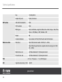
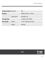
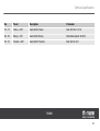
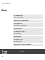
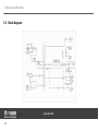
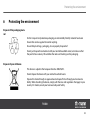
PM800
powermixer
user manual
Musikhaus Thomann e. K.
Treppendorf 30
96138 Burgebrach
Germany
Telephone: +49 (9546)-9223-0
email: [email protected]
Internet: www.thomann.de
17.11.2011
Table of contents
Table of contents
1
General notes............................................................................................................................................... 4
2
Safety instructions..................................................................................................................................... 6
3
Installation..................................................................................................................................................
3.1 Pin assignment..................................................................................................................................
3.2 Tips on speaker positioning.........................................................................................................
3.3 Connection diagram.......................................................................................................................
4
Control elements..................................................................................................................................... 15
5
Technical specifications.......................................................................................................................
5.1 Preset list.............................................................................................................................................
5.2 Features...............................................................................................................................................
5.3 Block diagram....................................................................................................................................
6
Protecting the environment.............................................................................................................. 33
10
10
13
14
25
28
30
32
PM800
3
General notes
1
General notes
This user manual contains important information on the safe operation of the device. Read and
follow all safety notes and all instructions. Save this manual for future reference. Make sure
that it is available to all persons using this device. If you sell the device to another user, be sure
that they also receive this manual.
Our products are subject to a process of continuous development. We therefore reserve the
right to make changes without notice.
Symbols and signal words
This section gives an overview of the symbols and signal words used in this user manual.
powermixer
4
General notes
Signal word
Meaning
DANGER!
This combination of symbol and signal word
indicates an immediate dangerous situation
that will result in death or serious injury if it is
not avoided.
CAUTION!
This combination of symbol and signal word
indicates a possible dangerous situation that
can result in minor injury if it is not avoided.
NOTICE!
This combination of symbol and signal word
indicates a possible dangerous situation that
can result in material and environmental
damage if it is not avoided.
Warning signs
Type of danger
Warning – high-voltage.
PM800
5
Safety instructions
2
Safety instructions
Intended use
Use the device only as described in this user manual. Any other use or use under other oper‐
ating conditions is considered to be improper and may result in personal injury or property
damage. No liability will be assumed for damages resulting from improper use.
This device may be used only by persons with sufficient physical, sensorial, and intellectual
abilities and having corresponding knowledge and experience. Other persons may use this
device only if they are supervised or instructed by a person who is responsible for their safety.
DANGER!
Electric shock caused by high voltages inside
Within the device there are areas where high voltages may be present. Never
remove any covers.
There are no user-serviceable parts inside.
powermixer
6
Safety instructions
DANGER!
Electric shock caused by short-circuit
Always use proper ready-made insulated mains cabling (power cord) with a pro‐
tective contact plug. Do not modify the mains cable or the plug. Failure to do so
could result in electric shock/death or fire. If in doubt, seek advice from a regis‐
tered electrician.
DANGER!
Electric shock caused by high voltages at the power amplifier output
The output voltages of modern high-performance amplifiers may result in death
or serious injury.
Never touch the bare ends of loudspeaker cables when the amplifier is on.
PM800
7
Safety instructions
CAUTION!
Possible hearing damage
With loudspeakers or headphones connected, the device can produce volume
levels that may cause temporary or permanent hearing impairment.
Do not operate the device permanently at a high volume level. Decrease the
volume level immediately if you experience ringing in your ears or hearing
impairment.
NOTICE!
Risk of fire
Do not block areas of ventilation. Do not install the device near any direct heat
source. Keep the device away from naked flames.
powermixer
8
Safety instructions
NOTICE!
Operating conditions
This device has been designed for indoor use only. To prevent damage, never
expose the device to any liquid or moisture. Avoid direct sunlight, heavy dirt, and
strong vibrations.
NOTICE!
Power supply
Before connecting the device, ensure that the input voltage (AC outlet) matches
the voltage rating of the device and that the AC outlet is protected by a residual
current circuit breaker. Failure to do so could result in damage to the device and
possibly injure the user.
Unplug the device before electrical storms occur and when it is unused for long
periods of time to reduce the risk of electric shock or fire.
PM800
9
Installation
3
Installation
Unpack and check carefully there is no transportation damage before using the unit.
Establish all connections as long as the unit is switched off. Use the shortest possible highquality cables for all connections.
3.1 Pin assignment
You can use XLR and phone jack connectors with either balanced or unbalanced wiring.
powermixer
10
Installation
XLR connection for signal in and
outputs
XLR mounting sockets provided for signal inputs. XLR mounting plugs provided for signal out‐
puts. Drawings and descriptions explain the pin assignment.
Balanced wiring:
1
Ground, shielding
2
Positive signal (+)
3
Negative signal (–)
Unbalanced wiring:
1
Ground, shielding
2
Signal
3
bridged with Pin 1
PM800
11
Installation
1/4" connectors for signal in and
outputs
Drawings and descriptions explain the pin assignment of 1/4" connectors.
Unbalanced wired 1/4" TS jack:
1
Signal
2
Ground, shielding
Unbalanced wired 1/4" TRS jack:
1
Signal
2
Ground, shielding
powermixer
12
Installation
Balanced wired 1/4" TRS jack:
1 (Tip)
Positive signal (+)
2 (Ring)
Negative signal (–)
3 (Sleeve)
Ground, shielding
3.2 Tips on speaker positioning
We recommend you to set up the speakers in a way, that the sound signals can reach the audi‐
ence unobstructedly. Often tripod mounting is a good way to maximise dispersion and range.
Always use high grade cable to connect your equipment. Otherwise you won't reach max‐
imum sound quality.
For optimum results both impedance and power handling of the speakers must match the
requirements of the amplifier. Always follow the technical specifications of the speakers! The
overall impedance of the connected loudspeakers must not deceed the minimum output
impedance of the amp. The power handling of the speakers should be above the amp's output
power.
PM800
13
Installation
3.3 Connection diagram
Before connecting the device you have to make sure, that all units are switched off and its
volume controls are turned down.
1. Connect line signal sources like CD or MP3 players to the unit.
2. Use high quality cables to connect passive speaker boxes to the output sockets (33).
3. Refer to the diagram shown above to connect further devices.
4. During operation turn the volume controls (LEVEL, 5) up to about 70 %.
5. Use the PFL function of the powermixer to adjust a suitable input level. Adjust the output
level using the MAIN LEVEL control (19).
powermixer
14
Control elements
4
Control elements
Front panel
SG/PEAK LED (1)
This LED lights up in green when a signal is present in the LINE/MIC input. When the signal
strength comes close to clipping, the LED turns red.
Mono input channels (2)
You can connect balanced, low impedance microphones or a low level signal to the XLR
socket. Use the 1/4" TRS (LINE IN) socket to connect instruments with line level outputs like
synthesizers, drum modules, preamps or the like.
NOTE: Never connect an unbalanced microphone to the XLR socket. Otherwise both the mic
and the mixer may be damaged.
PM800
15
Control elements
PHANTOM power switch and indicator (3)
Pressing this switch will apply +15 V phantom power to the XLR sockets. This voltage is
needed to supply condenser microphones. If you connect devices to the XLR sockets, that do
not require phantom power, make sure phantom power is turned off. Otherwise the device
may be damaged.
With phantom power activated, the PHANTOM indicator lights up, otherwise the LED is off.
DSP/FX AUX POST control (4)
This potentiometer is "post fader" configured and controls the "FX SEND" level. Thus, the
signal is affected by the channel fader. You can use the AUX1 signal to feed an external effect
processor.
LEVEL control (5)
Use this fader to set the desired volume of the respective channel from — ¥ to +10 dB.
3 band equalizer
Channels 1 - 8 offer a 3 band EQ, that provides a vast range for frequency correction.
powermixer
16
Control elements
HIGH (6)
This is the treble control. Use it to reduce high frequency noises or to boost the sound of e.g.
cymbals or high harmonics of voices. The gain range goes from -15 to +15 dB with a centre
frequency of 12 kHz.
MID (7)
This is the mid range control. It can affect the most fundamental frequencies of all musical
instruments and voices. An attentive use of this control will give you a very wide panorama
of sound effects. The gain range goes from -12 to +12 dB with a centre frequency of 2.5 kHz.
LOW (8)
This is the bass control. It is used to boost male voices, kick drum or bass guitar. This will sig‐
nificantly enhance the sound of your PA system. The gain range goes from -15 to +15 dB
with a centre frequency of 80 Hz.
PM800
17
Control elements
1/8" phone jack input (9)
Here you can connect a computer, MP3 or CD player using a 1/8" phone jack cable.
LEVEL 9-10 (10)
Use this control to adjust the level of both TAPE IN and 1/8" phone jack input (9). The adjust‐
able range goes from — ¥ to +10 dB.
TAPE IN (11)
Your power mixer offers 2 RCA inputs, where you can connect the R / L output of a tape
machine, DAT or cassette recorder.
TAPE OUT (12)
Use these outputs to route the main output signal into a tape / DAT device or computer for
recording.
powermixer
18
Control elements
12 V LAMP (13)
This XLR type lamp socket is provided for using a gooseneck lamp (PIN 1 = ground, PIN 2 =
+).
PHONES (14)
Use this control to adjust the level of the PHONES output (32).
MONITOR (15)
Use this control to adjust the level of the MONITOR OUT (29).
PM800
19
Control elements
Graphic EQ (16)
Your PM800 is equipped with a 7 band graphic EQ for the main mix. With these faders you
can boost or attenuate the selected frequency by 15 dB with a fixed bandwidth. With all
faders at centre position, the output response of the EQ is flat. The EQ function can be used,
to shape the contour of the frequency spectrum and is available, as soon as the unit is pow‐
ered up.
Output level LEDs (17)
Use these 4 LEDs to monitor the output power.
POWER indicator (18)
This LED will light up as soon as the unit is turned on.
LEVEL control (19)
This control is used to adjust the overall output level from —¥ to +10 dB.
DSP section
Your PM800 features a special 100-preset digital effects section. You will read more about
this later.
powermixer
20
Control elements
DSP display (20)
Here the unit displays the number of the current preset.
PROGRAM control (21)
Adjust this control to select the desired effect out of 100 options available: Echo, vocal, plate,
and versatile two-effect combinations. When you are satisfied with the chosen preset, push
this knob to confirm this preset.
DSP MUTE switch (22)
Use this switch to activate or deactivate the effect section. For a more convenient operation
of this function you can connect a foot switch (not supplied) to the "FOOT SWITCH" socket
(28).
CLIP/MUTE LED (23)
This LED lights up when either the input signal is too strong, or when the DSP section is
muted.
AUX/DFX RET (24)
This control is used to adjust the volume of the effects return signal.
PM800
21
Control elements
FX SEND (25)
Use this 1/4" jack socket to feed the signal from AUX bus to external devices like effects unit
or stage monitors.
FX RETURN (26)
This jack is used to return the signal processed by an external effects unit into the main mix.
You can also use it as an extra auxiliary input, if you're running short of "normal" input chan‐
nels.
COMP./LIM. switch and indicator (27)
Set the COMP./LIM switch to ON position, to prevent your signals from exceeding a threshold
that would cause distortion. If the input signal does not reach that threshold while this func‐
tion is activated, the indicator lights up in green. When the input signal becomes too strong
and exceeds the threshold, the indicator turns red.
FOOT SWITCH (28)
You can connect an external foot switch (not supplied) to this 1/4" socket, to turn the built-in
effects section on or off.
MONITOR OUT (29)
This socket is used to connect the input of an external monitor amp or active speakers.
powermixer
22
Control elements
MAIN OUT (30)
Use this socket to feed the main mix signal to an external device like a power amp or the like.
POWER switch (31)
This switch is used to turn the unit on or off.
PHONES output (32)
This socket sends out the monitor signal to a pair of headphones.
PM800
23
Control elements
REAR PANEL
OUTPUTS (33)
Connect your speakers to these output sockets (SPK and 1/4" sockets). The minimum output
impedance is 4 ohm.
AC INLET (34)
Connect the mains cable supplied here, to supply operating voltage to your powermixer.
VOLTAGE SELECTOR (35)
Use this switch to adjust the unit to the operating voltage available. When using the device
in Germany, this switch must be in "220 - 240 V" position. Otherwise the unit will be dam‐
aged and you're facing risk of electric shock.
Vents (36)
These are the ventilation openings used for heat dissipation and cooling. They must never be
obstructed during operation. Otherwise the unit may be damaged and you're facing risk of
fire.
powermixer
24
Technical specifications
5
Technical specifications
Input channels
Impedance
Equalization
Microphone inputs
electronically balanced, discrete inputs
Frequency response
20 Hz to 20 kHz, ± 3 dB
Gain
50 dB
Line inputs
electronically balanced
Frequency response
20 Hz to 20 kHz, ± 3 dB
Gain
20 dB
Microphone inputs
1.5 kohm
All other inputs
10 kohm or above
Tape out
1 kohm
All other outputs
120 ohm
Treble
± 15 dB @ 12 kHz
Mid range
± 12 dB @ 2.5 kHz
PM800
25
Technical specifications
DSP section
Main mix section
Bass
± 15 dB @ 80 Hz
Graphic EQ (sum)
7 band, 4/3 octave
A/D and D/A converters
24 bit
DSP resolution
24 bit
Effect types
Vocal, Small Room, Large Hall, Echo, Echo + Verb, Flange + Verb, Plate,
Chorus + GTR, Rotary + GTR, Tremolo + GTR
Presets
100
Controls/indicators
Preset control, CLIP-LED, MUTE switch with LED indicator
Noise (bus)
Fader 0 dB, channels muted: -85 dBr (ref.: +4 dBu)
Fader 0 dB, all input channels assigned and set to unity gain: -81 dBr
(ref.: +4 dBu)
THD
S/N
Monitor max. out
+22 dBu unbalanced, 1/4" phone jack socket
FX sends max. out
+22 dBu unbalanced, 1/4" phone jack socket
< 0.5 % @ 1 W power • < 1 % @ 250 W power
Signal-to-noise ratio @ 1 kHz > 65 dB
powermixer
26
Technical specifications
Static power consumption Without signal
< 50 W
Output power
250 W RMS @ 1 kHz THD = 1 %, 4 ohm Last
Frequency response
Power supply voltage
Dimensions/weight
20 Hz to 20 kHz, ± 3 dB
AC 220-240 V / 110-127 V 50/60 Hz
Dimensions
21.3" × 10.4" × 10.00" (540 × 265 × 256 mm)
Net weight
24 lbs (10.9 kg)
PM800
27
Technical specifications
5.1 Preset list
No.
Preset
Description
Parameter
00 ~ 09
Vocal
Simulates a small room
Decay time: 0.8~0.9 s
Pre-delay: 0~45 ms
10 ~ 19
Small room
Simulates a bright studio room
Decay time: 0.7~2.1 s
Pre-delay: 20~45 ms
20 ~ 29
Large hall
Simulates a large acoustic room
Decay time: 3.6~5.4 s
Pre-delay: 23~55 ms
30 ~ 39
Echo
Echo / delay effect
Delay time: 145~205 ms
40 ~ 49
Echo + verb
Echo & reverb combination
Delay time: 208~650 ms
Decay time: 1.7~2.1 s
50 ~ 59
Flange + verb
Flanger effect & reverb combination
Decay time: 1.5~2.9 ms
Rate: 0.8 Hz~2.52 Hz
60 ~ 69
Plate
Simulates classic, bright vocal plate
powermixer
28
Decay time: 0.9~3.6 s
Technical specifications
No.
Preset
Description
Parameter
70 ~ 79
Chorus + GTR
Guitar effect: Chorus
Rate: 0.92 Hz~1.72 Hz
80 ~ 89
Rotary + GTR
Guitar effect: Rotary
Modulation depth: 20~80 %
90 ~ 99
Tremolo + GTR
Guitar effect: Tremolo
Rate: 0.6 Hz~5 Hz
PM800
29
Technical specifications
5.2 Features
250 W output power @ 4 ohm
8 line inputs with 1/4" sockets
8 balanced microphone inputs with XLR sockets
3 band EQ for each channel
Monitor and effect send for each channel
7 band graphic main mix EQ
Signal / peak indicator for channels 1 - 8
Tape out for recording
Tape in with level control
1 AUX input with 1/8" socket
LED display for output level
Foot switch connector for switching DSP function on / off
powermixer
30
Technical specifications
Line outputs for main and monitor signal
Selectable power supply voltage (AC 110~127 V or AC 220~240 V)
PM800
31
Technical specifications
5.3 Block diagram
powermixer
32
Protecting the environment
6
Protecting the environment
Disposal of the packaging mate‐
rial
For the transport and protective packaging, environmentally friendly materials have been
chosen that can be supplied to normal recycling.
Ensure that plastic bags, packaging, etc. are properly disposed of.
Do not just dispose these materials with your normal household waste, but make sure that
they are fed to a recovery. Please follow the notes and markings on the packaging.
Disposal of your old device
This device is subject to the European directive 2002/96/EC.
Do not dispose the device with your normal household waste.
Dispose this device through an approved waste disposal firm or through your local waste
facility. When discarding the device, comply with the rules and regulations that apply in your
country. If in doubt, consult your local waste disposal facility.
PM800
33
Notes
powermixer
34
Musikhaus Thomann e.K. · Treppendorf 30 · 96138 Burgebrach · Germany · www.thomann.de