1
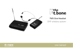
free solo PT
UHF wireless system
user manual
Musikhaus Thomann e.K.
Treppendorf 30
96138 Burgebrach
Germany
Telephone: +49 (0) 9546 9223-0
E-mail: [email protected]
Internet: www.thomann.de
22.01.2013
Table of contents
Table of contents
1
General notes............................................................................................................................................... 5
2
Safety instructions..................................................................................................................................... 7
3
Features....................................................................................................................................................... 11
4
Installation and starting up................................................................................................................
4.1 General information........................................................................................................................
4.2 Receiver...............................................................................................................................................
4.3 Transmitter.........................................................................................................................................
5
Connections and operating elements........................................................................................... 20
5.1 Receiver............................................................................................................................................... 20
5.2 Transmitter......................................................................................................................................... 28
6
Operating.................................................................................................................................................... 33
6.1 Receiver............................................................................................................................................... 33
6.2 Transmitter......................................................................................................................................... 36
7
Troubleshooting...................................................................................................................................... 41
12
12
14
18
free solo PT
3
Table of contents
8
Technical specifications....................................................................................................................... 44
8.1 Receiver............................................................................................................................................... 44
8.2 Transmitter......................................................................................................................................... 45
9
Protecting the environment.............................................................................................................. 47
UHF wireless system
4
General notes
1
General notes
This user manual contains important information on safe operation of the device. Read and
follow all safety notes and all instructions. Save this manual for future reference. Make sure
that it is available to all persons using this device. If you sell the device, include the manual for
the next owner.
Our products are subject to a process of continuous development. We therefore reserve the
right to make changes without notice.
Symbols and signal words
This section provides an overview of the symbols and signal words used in this user manual.
free solo PT
5
General notes
Signal word
Meaning
DANGER!
This combination of symbol and signal word
indicates an immediate dangerous situation
that will result in death or serious injury if it is
not avoided.
NOTICE!
This combination of symbol and signal word
indicates a possible dangerous situation that
can result in material and environmental
damage if it is not avoided.
Warning signs
Type of danger
Warning – danger zone.
UHF wireless system
6
Safety instructions
2
Safety instructions
Intended use
This device is intended to be used for the wireless transmission of audio signals from micro‐
phones or instruments to amplifiers or active speakers. Use the device only as described in this
user manual. Any other use or use under other operating conditions is considered to be
improper and may result in personal injury or property damage. No liability will be assumed for
damages resulting from improper use.
This device may be used only by persons with sufficient physical, sensorial, and intellectual
abilities and having corresponding knowledge and experience. Other persons may use this
device only if they are supervised or instructed by a person who is responsible for their safety.
free solo PT
7
Safety instructions
Safety
DANGER!
Danger for children
Ensure that plastic bags, packaging, etc. are disposed of properly and are not
within reach of babies and young children. Choking hazard!
Ensure that children do not detach any small parts (e.g. knobs or the like) from
the unit. They could swallow the pieces and choke!
Never let children unattended use electrical devices.
NOTICE!
Operating conditions
This device has been designed for indoor use only. To prevent damage, never
expose the device to any liquid or moisture. Avoid direct sunlight, heavy dirt, and
strong vibrations.
UHF wireless system
8
Safety instructions
NOTICE!
External power supply
The device is powered by an external power supply. Before connecting the
external power supply, ensure that the input voltage (AC outlet) matches the
voltage rating of the device and that the AC outlet is protected by a residual cur‐
rent circuit breaker. Failure to do so could result in damage to the device and pos‐
sibly the user.
Unplug the external power supply before electrical storms occur and when the
device is unused for long periods of time to reduce the risk of electric shock or
fire.
NOTICE!
Risk of fire due to incorrect polarity
Incorrectly inserted batteries may destroy the device or the batteries.
Ensure that proper polarity is observed when inserting batteries.
free solo PT
9
Safety instructions
NOTICE!
Possible damage by leaking batteries
Leaking batteries can cause permanent damage to the device.
Take batteries out of the device if it is not going to be used for a longer period.
UHF wireless system
10
Features
3
Features
The UHF Wireless System is especially suited for professional audio transmission, for example
at events, on rock stages and concert podiums, in theatres, musicals and discos.
Your UHF Wireless System free solo PT is comprised of the following components:
n 9.5" diversity receiver
– Two antennas for optimum reception quality
– Automatic frequency scanning
– Very high sensitivity at very high Signal-to-Noise Ratio
– Adjustable Squelch
– Outputs: XLR, 1/4" phone socket
– Mounting brackets for mounting in a 19" rack
– Operating voltage supply: DC 12 V , a suitable power supply is included
n Transmitter: battery powered bodypack transmitter
The system operates with 13 pre-programmed and one configurable frequency group with 16
presets each. The settings are transferred via an infrared interface from the receiver to the
transmitter.
free solo PT
11
Installation and starting up
4
Installation and starting up
4.1 General information
Unpack and check carefully there is no transportation damage before using the unit. Keep the
equipment packaging. To fully protect the device against vibration, dust and moisture during
transportation or storage use the original packaging or your own packaging material suitable
for transport or storage, respectively.
Establish all connections as long as the unit is switched off. Use the shortest possible highquality cables for all connections.
UHF wireless system
12
Installation and starting up
Notes on wireless transmission
n This devices utilizes frequencies that are not harmonized within the European Union (EU)
and therefore may only be used in certain EU member states. In all European countries, the
frequencies used for the transmission of audio signals are strictly regulated. Before you
start, make sure the frequencies are allowed in the respective country and check whether
the operation must be reported to the appropriate authority.
n Make sure that transmitter and receiver are both tuned to the same channel.
n Never set multiple transmitters to the same channel.
n Make sure that there are no metal objects between the transmitter and receiver.
n Avoid interference from other radio systems, television or radio sets.
free solo PT
13
Installation and starting up
4.2 Receiver
XLR connection for signal
output on the receiver
An XLR chassis socket serves as signal output on the receiver. Drawing and table indicate the
XLR pin assignment (balanced wiring).
1
Ground, shielding
2
Positive signal (+)
3
Negative signal (–)
UHF wireless system
14
Installation and starting up
Phone plug for signal output on
the receiver
A 1/4" phone socket (TS) serves as signal output on the receiver. Drawing and table indicate
the pin assignment of a suitable plug.
Rack mounting
1
Signal
2
Ground, shielding
The device is 19" rack mountable, it occupies 1 rack unit (RU). Necessary mounting material is
enclosed.
free solo PT
15
Installation and starting up
Connecting the power supply
NOTICE!
External power supply
The device is powered by an external power supply. Before connecting the
external power supply, ensure that the input voltage (AC outlet) matches the
voltage rating of the device and that the AC outlet is protected by a residual cur‐
rent circuit breaker. Failure to do so could result in damage to the device and pos‐
sibly the user.
Unplug the external power supply before electrical storms occur and when the
device is unused for long periods of time to reduce the risk of electric shock or
fire.
First, connect the power supply to the receiver and then plug the power adapter into the
power outlet.
UHF wireless system
16
Installation and starting up
Mounting antennas
Attach the supplied antennas to the rear panel of the receiver. To improve transmission quality
and to adapt to the spatial conditions the antennas are rotatable and swivelling.
If the space for the direct mounting of the antennas on the unit is not sufficient, for example,
because of restricted space in the rack, you can use the optional coaxial cable to mount the
antennas separated from the unit. For larger configurations with up to four receivers, the
usage of the optional antenna distributor is appropriate.
Audio connection and starting
up
Connect one of the audio outputs of the receiver to your mixing console or amplifier. Make
sure that only one of both output is used at a time. Otherwise, malfunction may occur.
free solo PT
17
Installation and starting up
4.3 Transmitter
Mini XLR connection for signal
input on the transmitter
Inserting batteries into the
transmitter
A mini XLR chassis plug serves as signal input on the transmitter. Drawing and table indicate
the mini XLR pin assignment.
1
Ground, shielding
2
Positive signal (+)
3
Negative signal (–)
Slide the cover of the battery compartment into arrow direction to open it. Insert the batteries
respecting the correct polarity. Close the battery compartment and turn the transmitter on.
The ‘LOW BATT’ LED briefly lights up.
UHF wireless system
18
Installation and starting up
Connecting a microphone or
instrument to the transmitter
n Make sure that the transmitter is switched off.
n Connect the microphone or instrument cable to the input of the transmitter (mini XLR
chassis plug).
n Turn on the transmitter and test the transmission with the microphone or the instrument.
If necessary, adjust the gain of the transmitter and the levels on your mixer or your amp.
free solo PT
19
Connections and operating elements
5
Connections and operating elements
5.1 Receiver
Front panel
UHF wireless system
20
Connections and operating elements
1 POWER
Press the button for several seconds to turn the unit on or off. Briefly press the button to mute the input.
All previous settings are saved even if you turn off the power and disconnect the unit from the mains.
2 Infrared sensor.
3 [ADS] button
Starts the synchronization of the settings with the transmitter.
4 Display.
5 [SET] button
Opens up the menu.
6
button
Increases the displayed value by one.
7
button
Decreases the displayed value by one.
free solo PT
21
Connections and operating elements
8 [AUTO] button
Starts the automatic search for a free channel.
12, 13 Calibrated UHF antennas.
The receiver evaluates the radio signal received by both antennas and selects the signal with the higher quality for
further processing.
UHF wireless system
22
Connections and operating elements
Rear panel
free solo PT
23
Connections and operating elements
9 DC 12-18V
Socket to connect the supplied mains adapter. If you use a different power supply, observe the correct voltage, the
polarity of the plug and the power consumption.
10 BALANCED OUTPUT
XLR chassis connector as balanced audio signal output for direct connection to a mixer, a power amplifier or
recording device.
11 UNBALANCED OUTPUT
1/4" phone socket as unbalanced audio signal output for direct connection to a mixer, a power amplifier or recording
device.
12, 13 ANTENNA-B, ANTENNA-A
Calibrated UHF antennas.
The receiver evaluates the radio signal coming from both antennas and selects the signal with the higher quality for
further processing.
14 Indication of the frequency range in which the device operates. The indication here must match the specification on
the transmitter.
UHF wireless system
24
Connections and operating elements
Display
free solo PT
25
Connections and operating elements
15 GP
Indicates the selected frequency group.
16 CH
Indicates the selected channel.
17
Indicates that the unit is locked to prevent unintentional operation.
18
Indicates that the unit is muted.
19 A/B
Indicates which of both antennas is currently used for signal transmission.
20 SQ
Displays the adjusted level of the squelch for the radio signal. A too high squelch level reduces the dynamics of the
system.
21 RF
Indicates the level of the received radio signal.
UHF wireless system
26
Connections and operating elements
22 Shows the battery status of the transmitter from which the device is currently receiving a signal.
23 AUTO
Indicates that the automatic search for a free channel is running.
24 IR
Indicates that an IR signal is received.
25 FREQUENCY
Indication of the frequency that is assigned to the set combination of frequency group and channel.
26 AF
Audio level indicator.
free solo PT
27
Connections and operating elements
5.2 Transmitter
Front panel
UHF wireless system
28
Connections and operating elements
31 Display.
32 Antenna.
33 MUTE LED
Indicates that the unit is muted.
34 BATT LOW / ON LED
Flashes when the battery level is too low.
35 [SET] button
Opens up the menu.
36
/
buttons
Increases or decreases the currently shown value.
37 Battery holder for two AA cells (LR06), 1.5 V, or equivalent rechargeable batteries.
38 IR
Infrared sensor.
free solo PT
29
Connections and operating elements
39 INPUT
Mini XLR chassis plug to connect a microphone or instrument.
40 Main switch
Press the button for several seconds to turn the unit on or off. Briefly press the
button to mute the input.
41 Indication of the frequency range in which the device operates. The indication here
must match the specification on the rear panel of the receiver.
42 Belt clip.
UHF wireless system
30
Connections and operating elements
51 FREQUENCY / GP / CH
Depending on the selected menu item:
n Indication of the frequency that is assigned to the set combination of fre‐
quency group and channel.
n Indication of the set frequency group and the selected channel.
52
Indicates that the unit is locked to prevent unintentional operation.
53 GAIN
Indicates the level of the transmitted radio signal.
54 Battery status display. Replace the batteries as soon as only one flashing cursor is
left in the display. If the voltage of the batteries drops even further, the transmitter
will automatically shut off. The battery status is also shown on the receiver.
free solo PT
31
Connections and operating elements
55
Indicates that the transmitter is muted. This is the case when transmitter and
receiver operate on different frequencies, if the receiver does not receive a usable
signal or if you have muted the transmitter by briefly pressing the main switch.
56 Indicates the output power.
UHF wireless system
32
Operating
6
Operating
6.1 Receiver
Selecting the frequency
1.
Press [SET].
ð The GP display is flashing.
2.
Use the arrow keys to select the frequency group.
Press [SET] to confirm the selection.
ð The CH display is flashing.
3.
Use the arrow keys to select a channel within the selected frequency group.
If you have selected the frequency group ‘U’, you can directly set the frequency using
the arrow keys. First, set the value to the left of the decimal point, then press [SET] and
after that set the value to the right of the decimal point.
Press [SET] to confirm the selection.
free solo PT
33
Operating
ð The display indicates that the receiver is being calibrated to a new frequency. After a
few seconds the display will return to the default state.
Synchronising transmitter and
receiver
1.
Open the transmitter to uncover the infrared sensor.
2.
Press [ADS]. The IR display is flashing.
3.
Within ten seconds, hold the infrared sensor of the transmitter close to the infrared inter‐
face of the receiver.
4.
The IR display stops flashing when the synchronisation is successfully completed.
ð After three seconds, the display returns to the default state.
UHF wireless system
34
Operating
Setting the squelch
1.
Press [SET] as long until the SQ area is flashing in the display.
2.
Use the arrow keys to set the desired value. The current value is shown on the right side
of the display.
3.
Press [SET] to confirm the selection.
ð After three seconds, the display returns to the default state.
Automatic search for a free
channel
1.
Press [AUTO].
ð The AUTO display is flashing, the display shows the number of available free chan‐
nels.
2.
Use the arrow keys to select one of the free channels.
Press [SET] to confirm the selection.
ð After three seconds, the display returns to the default state.
3.
If the system does not find a free channel within five seconds, it automatically returns to
the default state.
free solo PT
35
Operating
Turning key lock on or off
1.
Press [SET] as long until the symbol appears.
ð All buttons are locked except the main switch.
2.
To turn the key lock off, press [SET] again as long until the symbol disappears.
ð The buttons have regained their original function.
6.2 Transmitter
The operating buttons of the device are located under the front side flap.
UHF wireless system
36
Operating
Frequency selecting
If you don't want to synchronise the transmitter via the infrared interface with the receiver, you
can also set the transmission frequency manually.
1.
Press [SET] repeatedly until the value in the GP field of the display is flashing.
2.
Use the arrow keys to select the frequency group.
Press [SET] to confirm the selection.
ð The figure in the CH field is flashing.
3.
Use the arrow keys to select a channel within the set frequency group.
If you have selected the frequency group ‘U’, you can directly set the frequency using
the arrow keys. First, set the value to the left of the decimal point, then press [SET] and
after that set the value to the right of the decimal point.
Press [SET] to confirm the selection.
ð After a few seconds the display will return to the default state.
free solo PT
37
Operating
Setting transmission gain
1.
Press [SET] repeatedly until the figure in the GAIN field is flashing.
2.
Use the arrow keys to adjust the transmission gain in increments of 3 dB (–9 dB, –6 dB,
–3 dB, 0 dB, 3 dB).
Press [SET] to confirm the selection. Press the main switch to exit the menu without any
changes.
Setting transmitting power
1.
Press [SET] repeatedly until the
2.
Use the arrow keys to change the transmitting power (5 mW, 10 mW, 20 mW).
symbol is flashing in the display.
Press [SET] to confirm the selection. Press the main switch to exit the menu without any
changes.
UHF wireless system
38
Operating
Frequency group and channel
display
1.
Press .
ð The display indicates the used frequency group und the used channel.
2.
Press [SET] or wait for five seconds to return to the default state.
Turning key lock on
Press
as long until the symbol appears.
ð All buttons are locked, except the main switch.
free solo PT
39
Operating
Turning key lock off
1.
To turn the key lock off press
and then [SET].
ð The symbol is flashing.
2.
Press
again and then [SET].
3.
Press
a third time and then [SET].
ð The symbol disappears. The buttons have regained their original function.
UHF wireless system
40
Troubleshooting
7
Troubleshooting
In the following we list a few common problems that may occur during operation. We give you
some suggestions for easy troubleshooting:
free solo PT
41
Troubleshooting
Symptom
Remedy
No sound
1. Check the power supply of the transmitter and receiver.
2. Make sure that both transmitter and receiver operate in the same frequency
range. The frequency range is stated on the devices.
3. Are both transmitter and receiver set to the same channel?
4. Check the connection between the receiver and the connected audio device
(amp, mixer). Is the connected audio device switched on and does the signal
level on the output of the receiver match the input sensitivity of the audio
device?
5. Try to improve the transmission by moving the transmitter closer to the
receiver.
6. Make sure that no metal objects near the transmitter or receiver obstruct the
transmission.
Transmission is disturbed
1. Modify the orientation of the antennas.
2. If you use more than one wireless system at the same time, check the used
frequencies and channels.
3. Interference can also be caused by televisions, radios or mobile phones.
UHF wireless system
42
Troubleshooting
If the procedures recommended above do not succeed, please contact our Service Center. You
can find the contact information at www.thomann.de.
free solo PT
43
Technical specifications
8
Technical specifications
8.1 Receiver
Outputs
XLR chassis plug, balanced
1/4" phone socket, unbalanced
Carrier frequency
UHF band (600 MHz…900 MHz)
Number of channels
208
Switching bandwidth
25 MHz
Modulation type
Frequency modulation (FM)
Sensitivity
–102 dBm
NF frequency response
50 Hz…15 kHz (±3 dB)
THD
< 0.8 %
Signal-to-noise ratio
> 105 dB (A)
UHF wireless system
44
Technical specifications
Operating supply voltage
DC 12 V
Dimensions (W × D × H, without antennas)
212 mm × 160 mm × 44 mm
Weight
900 g
8.2 Transmitter
Carrier frequency
UHF band (600 MHz…900 MHz)
Frequency band
the t.bone free solo PT 600 MHz (item no. 296201): 596 MHz…620 MHz
the t.bone free solo PT 740 MHz (item no. 296203): 740 MHz…752 MHz
the t.bone free solo PT 823 MHz (item no. 296204): 823 MHz…832 MHz
the t.bone free solo PT 863 MHz (item no. 296206): 863 MHz…865 MHz
Number of channels
208
Switching bandwidth
25 MHz
free solo PT
45
Technical specifications
Modulation type
Frequency modulation (FM)
Transmission power
the t.bone free solo PT 600 MHz (item no. 296201): 20 mW
the t.bone free solo PT 740 MHz (item no. 296203): 20 mW
the t.bone free solo PT 823 MHz (item no. 296204): 20 mW
the t.bone free solo PT 863 MHz (item no. 296206): 10 mW
Spurious response rejection
> 55 dBc
Peak deviation
± 55 kHz
NF frequency response
60 Hz…18 kHz
THD
< 0.5 %
Signal-to-noise ratio
> 102 dB (A)
Operating supply voltage
2 AA cells (LR06, 1.5 V) or equivalent rechargeable batteries
Battery life span
> 8 h (with alkaline cells)
Dimensions (W × D × H, without antennas)
64 mm × 23 mm × 98 mm
Weight
90 g
UHF wireless system
46
Protecting the environment
9
Protecting the environment
Disposal of the packaging mate‐
rial
For the transport and protective packaging, environmentally friendly materials have been
chosen that can be supplied to normal recycling.
Ensure that plastic bags, packaging, etc. are properly disposed of.
Do not just dispose these materials with your normal household waste, but make sure that
they are fed to a recovery. Please follow the notes and markings on the packaging.
Disposal of batteries
Batteries must not be disposed of as domestic waste or thrown into fire. Dispose of the bat‐
teries according to national or local regulations regarding hazardous waste. To protect the
environment, dispose of empty batteries at your retail store or at appropriate collection sites.
free solo PT
47
Protecting the environment
Disposal of your old device
This device is subject to the European directive 2002/96/EC. Do not dispose the device with
your normal household waste.
Dispose this device through an approved waste disposal firm or through your local waste
facility. When discarding the device, comply with the rules and regulations that apply in your
country. If in doubt, consult your local waste disposal facility.
UHF wireless system
48
Notes
free solo PT
49
Notes
UHF wireless system
50
Musikhaus Thomann e.K. · Treppendorf 30 · 96138 Burgebrach · Germany · www.thomann.de