1
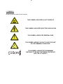
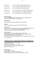
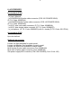
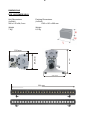
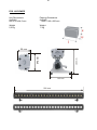
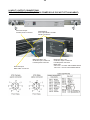
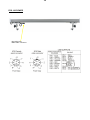
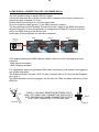
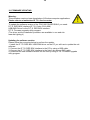
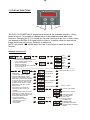
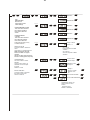
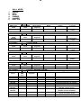
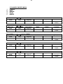
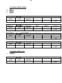
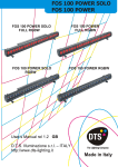
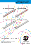
2
Le informazioni contenute in questo documento sono state attentamente redatte e
controllate. Tuttavia non è assunta alcuna responsabilità per eventuali inesattezze. Tutti i
diritti sono riservati e questo documento non può essere copiato, fotocopiato, riprodotto
per intero o in parte senza previo consenso scritto della D.T.S .
D.T.S. si riserva il diritto di apportare senza preavviso cambiamenti e modifiche
estetiche, funzionali o di design a ciascun proprio prodotto. D.T.S non assume alcuna
responsabilità sull’uso o sull’applicazione dei prodotti o dei circuiti descritti.
The information contained in this publication has been carefully prepared and checked.
However, no responsibility will be taken for any errors. All rights are reserved and this
document cannot be copied, photocopied or reproduced, in part or completely, without
prior written consent from D.T.S.
D.T.S. reserves the right to make any aesthetic, functional or design modifications to any
of its products without prior notice. D.T.S. assumes no responsibility for the use or
application of the products or circuits described herein.
Les informations contenues dans le présent manuel ont été rédigées et contrôlées avec
le plus grand soin. Nous déclinons toutefois toute responsabilité en cas d'éventuelles
inexactitudes. Tous droits réservés. Ce document ne peut être copié, photocopié ou
reproduit, dans sa totalité ou partiellement, sans le consentement préalable de D.T.S.
D.T.S. se réserve le droit d'apporter toutes modifications et améliorations esthétiques,
fonctionnelles ou de design, sans préavis, à chacun de ses produits. D.T.S. décline toute
responsabilité sur l'utilisation ou sur l'application des produits ou des circuits décrits.
Las informaciones contenidas en este documento han sido cuidadosamente redactadas
y controladas. Con todo, no se asume ninguna responsabilidad por eventuales
inexactitudes. Todos los derechos han sido reservados y este documento no puede ser
copiado, fotocopiado o reproducido, total o parcialmente, sin previa autorización escrita
de D.T.S.
D.T.S. se reserva el derecho a aportar sin previo aviso cambios y modificaciones de
carácter estético, funcional o de diseño a cada producto suyo. D.T.S. no se asume
responsabilidad de ningún tipo sobre la utilización o sobre la aplicación de los productos
o de los circuitos descritos.
3
INDEX:
1- SYMBOLS
2- GENERAL WARNING
3- GENERAL WARRANTY CONDITION
4- TECHNICAL FEATURES
5- MAIN ELECTRICAL CHARACTERISTICS
6- ACCESSORIES
7- IMPORTANT SAFETY INFORMATION
7.1 Fire prevention
7.2 Prevention of electric shock
7.3 Safety
8- INPUT / OUTPUT CONNECTIONS
9- DMX SIGNAL CONNECTION
9.1 DMX Addresses
9.2 Selecting the DMX address
10- FIRMWARE UPDATING
11- DISPLAY FUNCTIONS
12- SERVICE MENU
13- DMX PROTOCOL
4
5
5
5
6
7
10
11
13
15
16
20
22
4
1- SYMBOLS
Graphic symbols used on this manual
THIS SYMBOL INDICATES A HOT SURFACE
THIS SYMBOL INDICATES ELECTRIC SHOCK RISK
!
THIS SYMBOL INDICATES GENERAL RISK
THIS SYMBOL MEANS “DO NOT PLACE THE UNIT
ON INFLAMMABLE SURFACES”
F
10cm
THIS SYMBOL INDICATES THE MINIMUM
DISTANCE TO BE KEPT BETWEEN THE DEVICE
AND THE LIT OBJECT
5
2- GENERAL WARNING
Read the instruction contained in this user manual carefully, as they give important
information regarding safety during installation, use and maintenance.
The device is not for domestic use and must be installed by a qualified electrician or
experienced person.
Always disconnect the device from the mains before maintenance.
The device must always be equipped with an efficient ground connection.
3- GENERAL WARRANTY CONDITIONS
The unit is guaranteed for 36 months from the date of purchase against manufacturing
material defects.
4- TECHNICAL FEATURES
OVERVIEW
Delivering no less than 8.400 Lux / 3m, the new FOS 100 POWER is the most powerful
model in the FOS line of compact LED bars, designed for lighting and colouring large
surfaces with a homogeneous projection.
FOS 100 POWER is ideal in a variety of applications, either indoor or outdoor, such as:
lighting building facades, monuments, public and commercial spaces; creating uniform
background colours and cycloramas, etc.
FOS 100 POWER is available in two versions.
FOS 100 POWER FULL COLOUR: 24 x Full Colour (RGBW) LEDs;
FOS 100 POWER RGBW: 96 x RGBW LEDs.
Three dedicated lenses sets (Spot, Medium flood, Wide flood) are available for each
model.
PRODUCT CODES:
03.LB031S.T10
FOS 100 POW.SOLO IP65 RGBW NARROW BLACK
03.LB031S.T25
FOS 100 POW.SOLO IP65 RGBW MEDIUM BLACK
03.LB031S.T40
FOS 100 POW.SOLO IP65 RGBW WIDE BLACK
03.LB031S.F10
FOS 100 POW.SOLO IP65 FULLRGBW NARROW BLACK
03.LB031S.F25
FOS 100 POW.SOLO IP65 FULLRGBW MEDIUM BLACK
03.LB031S.F40
FOS 100 POW.SOLO IP65 FULLRGBW WIDE BLACK
6
03.LB031.T10
FOS 100 POWER IP65 RGBW NARROW BLACK
03.LB031.T25
FOS 100 POWER IP65 RGBW MEDIUM BLACK
03.LB031.T40
FOS 100 POWER IP65 RGBW WIDE BLACK
03.LB031.F10
FOS 100 POWER IP65 FULLRGBW NARROW BLACK
03.LB031.F25
FOS 100 POWER IP65 FULLRGBW MEDIUM BLACK
03.LB031.F40
FOS 100 POWER IP65 FULLRGBW WIDE BLACK
LED Technology
FOS 100 POWER FULL COLOUR: 24 x Full Colour (RGBW) LEDs;
FOS 100 POWER RGBW: 96 x RGBW LEDs.
Optical group
3 lenses sets available (Spot, Medium flood, Wide flood)
Control
Via any DMX lighting console (FOS 100 POWER SOLO)
Connectors
M16 connection system between Power supply and LED bar (All versions).
Powerconn + XLR connectors (FOS 100 POWER SOLO IP20);
Harting connectors (FOS 100 POWER SOLO IP65*)
Power supply
Electronic full range power supply 90-260V - AC/50-60 Hz
Integrated power supply (FOS 100 POWER SOLO) / LED controller
(Z10 POWER IP65* or Z10 POWER IP20);
External dedicated Z40 power supply (FOS 100 POWER) / LED controllers
* not yet available
5- MAIN ELECTRICAL CHARACTERISTICS (FOS 100 POWER SOLO)
Input Voltage Range : Vin 90 - 260 Vac
Frequency : 50 / 60 Hz
Power Consumption Range : 10 - 200 W
Power Factor (Pf) : 0.95 electronic PFC controller
Efficiency : 90% typical
Control Input:
Control Signal : DMX 512
Dimming System : Constant Current PWM
Address Range : DMX 512 channels addressable by display
7
6- ACCESSORIES
As standard (IP20)
1 x User’s Manual
1 x POWERCON IN male cable connector (FOS 100 POWER SOLO)
(D.T.S. Code: 0520P014)
1 x POWERCON OUT male cable connector (FOS 100 POWER SOLO)
(D.T.S. Code: 0520P029)
1 x XLR 5 pins male cable connector (D.T.S. Code: 0508B028)
1 x XLR 5 pins female cable connector (D.T.S. Code: 0508B027)
1 x joint/spacer (D.T.S. Code: 00M09519) with 2 x knobs (D.T.S. Code: 0511P014)
As standard (IP65)
Up to be defined
Optional (on request)
Lenses set Spot available for each model
Lenses set Medium flood available for each model
Lenses set Wide flood available for each model
M16 female (9 pole) cable connector (Cod. 0508B106)
M16 male (9 pole) cable connector (Cod. 0508B105)
Z40 power supply/LED controller (FOS 100 POWER) (Cod. 03.LA.120)
8
DIMENSIONS
FOS 100 POWER SOLO
Unit Dimensions
(LxWxH)
990 x 100 x 84,5 mm
Packing Dimensions
(LxWxH)
1060 x 160 x 200 mm
Weight
7 Kg
Weight
8,5 Kg
160 mm
84,5 mm
100 mm
140 mm
990 mm
9
FOS 100 POWER
Unit Dimensions
(LxWxH)
990 x 56 x 84,5 mm
Packing Dimensions
(LxWxH)
1060 x 160 x 200 mm
Weight
5,5 Kg
Weight
7 Kg
160 mm
84,5 mm
56 mm
140 mm
990 mm
10
7- IMPORTANT SAFETY INFORMATION
7.1 Fire prevention:
Never locate the fixture on any flammable surface.
Minimum distance from flammable materials: 10 cm. F
Minimum distance from the closest illuminable surface: 10 cm. 10cm
Replace any blown or damaged fuses only with those of identical value.
7.2 Prevention from electric shock:
High voltage is present inside the unit.
Unplug the unit prior to performing any operation which involves touching the inside of
the unit.
This equipment must be grounded, do not connect to non-grounded supplies.
The use of a thermal magnetic circuit breaker is recommended for each FOS 100
POWER SOLO unit.
Use only AC supplies 90-260V, 50 / 60 Hz.
FOS 100 POWER SOLO (IP 20) should never be located in position exposed to rain or in
areas of extreme humidity.
A good air ventilation is essential for proper equipment work.
!
7.3 Safety:
The external surface of the unit may exeed 50°C; never handle the unit until at least 5
minutes have elapsed since the unit was turned off.
Never install the unit in an enclosed area lacking sufficient air flow.
The ambient temperature should not exeed 40°C and should not be lower than -10°C.
11
8- INPUT / OUTPUT CONNECTIONS
FOS 100 POWER SOLO IP20 (FOS 100 POWER SOLO IP65 NOT YET AVAILABLE)
M16 LED output
Female panel connector
DMX IN/OUT
XLR 5 pins Male / Female
Panel Connectors
Mains 90-260 V AC
50-60 Hz input Powercon
Female panel connector
M16 LED input
Male cable connector
Mains 90-260 V AC
50-60 Hz output Powercon
Female panel connector
MAX load:
230 V AC = 10 FOS 100 POWER SOLO
100 V AC = 5 FOS 100 POWER SOLO
12
FOS 100 POWER
M16 LED input
Male cable connector
13
9- DMX SIGNAL CONNECTION (FOS 100 POWER SOLO):
The unit operates using a digital DMX 512 signal.
Connection between the controller and the unit or between units must be carried out
using a two pair screened ø 0.5 mm.
Ensure that the conductors do not touch each other.
Do not connect the cable ground to the DMX connector chassis.
The plug housing must be isolated. Connect the mixer signal to the DMX IN projector
plug and connect it to the next projector by connecting the DMX OUT plug on the first
unit to the DMX IN plug of the second one.
In this way, all the projectors are cascade connected.
CONTROLLER
S TA N D A R D
DMX 512
5
1
4
2
UNIT 1
UNIT 2
UNIT 3
1=GND
2=DATA3=DATA+
3
If the display showing the DMX address flashes, then one of the following errors has
occurred:
- DMX signal not present
- DMX reception problem
For Installations where long distance DMX cable connections are needed, we suggest to
use a DMX terminator.
The DMX terminator is a male XLR 3-5 pins connector with a 120 ohm resistor Between
pin 2 and 3.
The DMX terminator must be plugged into the last unit (DMX out panel connector) of the
DMX line.
5
1
4
2
3
120 ohm
OUT
PLACE A 120 OHM RESISTOR BETWEEN PIN 2
AND 3 OF A MALE XRL CONNECTOR AND PLUG IT
INTO THE DMX OUT PANEL CONNECTOR OF THE
LAST UNIT CONNECTED TO THE DMX LINE
PIN 3
PIN 2
14
9.1 DMX addresses
FOS 100 POWER SOLO (all models) can be used in seven different modes: 10 DMX
channels mode (default), 6 DMX channels mode (Shutter + Dimmer + RGBA), WALL
mode (6 DMX channels; for use with DTS Wall mounted DMX controller 0514L007),
M4CH mode (5 DMX channels; Dimmer + RGBA), RGBA mode (4 channels), 1 DMX
channel mode or CUSTOM DMX mode (not yet implemented).
If you want to use the FOS 100 POWER SOLO in 10 channels mode, select the 10 CH
mode from the MODE menu and set the following addresses on the mixer:
Projector 1
Projector 2
Projector 3
…..
projector 6
A001
A011
A021
A….
A051
If you want to select the next projector, just add “10”
If you want to use the FOS 100 POWER SOLO in “WALL” mode, select the “WALL”
mode from the MODE menu and set the following addresses on the mixer: (To be used
only with DTS Wall mounted DMX controller 0514L007)
Projector 1
Projector 2
Projector 3
….. A….
projector 6
A001
A009
A017
If you want to select the next projector, just add “8”.
DTS Wall mounted DMX controller 0514L007 assign
8 DMX channels per unit even if some channels are
not used
A041
9.2 Selecting the DMX address
1) Press the UP-DOWN key until you reach the required DMX address. The numbers on
the display will start to flash (but the new DMX address hasn't yet been set).
2) Press ENTER to confirm your selection. The numbers on the display will stop flashing
and the projector is now controlled by the new DMX address.
TIPS: if you keep pushed the UP or DOWN keys, the channels are calculated more
quickly and you get a faster selection.
15
10- FIRMWARE UPDATING
Warning:
This procedure require a base knowledge of Windows computer applications.
Please refer to an authorised D.T.S. service centre.
!
To update the software version of the FOS 100 POWER SOLO you need:
D.T.S. RED BOX interface (D.T.S. Code: 03.LA.008).
USB-DMX Driver for the D.T.S. RED BOX interface.
D.T.S. Firmware upgrade utility program.
(The driver and the installation procedure are available in our web site
www.dts-lighting.it)
Updating the software version.
Please follow the procedure below to perform the update:
1. Install the D.T.S. RED BOX USB-DMX driver on the PC you will use to update the unit
software.
2. Connect the D.T.S. RED BOX interface to the PC by using a USB cable.
3. Connect the D.T.S. RED BOX interface to the fixture by using a DMX cable.
4. Download the new software version into the unit by using D.T.S. Firmware upgrade
utility program.
16
11- DISPLAY FUNCTIONS
MENU
ENTER
UP
DOWN
The FOS 100 POWER SOLO display panel shows all the available functions . Using
these functions, it is possible to change some of the parameters and add some
functions. Changing the D.T.S. setting can vary the functions of the unit so that it does
not respond to the DMX 512 signal used to control it. Carefully follow the instructions
below before carrying out any variations or selections.
NOTE: the symbol
shows which key has to be pushed to obtain the desired
function.
Software version 4.0.7
MENU
Up-Down
ENTER
Up-Down
ENTER
Floor
Position
Suspension
Position
Up-Down
REVERSE DISPLAY
Reverses display's reading depending
on the mounting position (On the
Up-Down
ground or suspended).
ENTER
Display
OFF
Up-Down
DISPLAY STAND BY
To turn off the display (after 5 seconds)
.
or leave it always on.
MENU
Up-Down
ENTER
DMX MODE
To select DMX mode : 10 DMX
channels mode (default), 6 DMX
channels mode (Shutter + Dimmer +
RGB), WALL mode (6 DMX channels;
for use with DTS Wall mounted DMX
controller 0514L007), M3CH mode
(4 DMX channels; Dimmer + RGB),
RGB mode (4 channels), 1 DMX
channel mode.
AUX mode let you activate an
external ON -OFF control on IR
connector.
CUSTOM DMX mode let you set the
parameters for Shutter, Dimmer, Red,
Green, Blue, Ctc, Macro and Function
to the desired DMX channels.
(not yet implemented)
MACRO Function enables
channel mapping macro
rainbow effects
STD (default)
Display
Always ON
Up-Down
10 CHANNELS
ENTER
Up-Down
6 CHANNELS
ENTER
Up-Down
Up-Down
Up-Down
Up-Down
Up-Down
1 CHANNEL
ENTER
ENTER
ENTER
RGBA(4 CHANNELS) ENTER
6 CHANNELS
ENTER
M4CH(5 CHANNELS) ENTER
ENTER
Dimmer + RGBA
ENTER
Up-Down
AUX MODE
ENTER
Up-Down
ENTER
Custom mode enabled
Show Custom settings
Parameters Setting
on Custom Mode
External ON – OFF
control on IR connector
Standard mode
enabled (Default)
ENTER
Extended mode enabled:
ENTER
Rainbow effects on MACRO
channel
ENTER
Up-Down
ENTER
Default DMX Mode = 10 CH
ENTER
Up-Down
ENTER
17
MENU
Up-Down
ENTER
LED
RGBA Min/Max,
Smooth and
Compression levels
values settings
Up-Down
ENTER
Up-Down
ENTER
Default=0
ENTER
ENTER
Default=0
Up-Down
ENTER
Default=100
Up-Down
ENTER
Up-Down
SMOOTH VALUE
This menu allow to select the
value
of the delay ( in milliseconds) for
RGB and Dimmer channels
reaction to DMX or Program
variation.
Off=25 ms delay (Fast response)
20=250 ms delay (Slow response)
BOOST DRIVING
This menu allow to increase
the LED’s current from
350mA to 500 mA
Default=100
Up-Down
on Master Dimmer
COMPRESSION
This menu allow to select
between
Linear courrent output or
Quadratic courrent output
for LEDs
Default = Linear
ENTER
Default=100
ENTER
RGBA MAXIMUM
VALUES
This menu allow to select
the maximum levels for
Red, Green, Blue and
Ambersettings have priority
These
Default=0
Up-Down
ENTER
RGBA MINIMUM VALUES
This menu allow to select
the minimum levels for
Red, Green, Blue and
Amber
Up-Down
ENTER
Range = Off-20
Default = 4
ENTER
Off = 25 ms
Instant response to DMX
variation
20 = 250 ms
Smooth response to DMX
variation
Up-Down
ENTER
Up-Down
Linear=Linear
current output
Quadratic=Linear
light output
Up-Down
ENTER
ENTER
Up-Down
Up-Down
ENTER
ENTER
Range =
610 Hz -10 KHz
Default = 610
Hz
Boost mode activated
Boost mode deactivated
Up-Down
With BOOST active, the
LED’s current is set to
500mA
(30%more gain).
Default = Activated
ENTER
ENTER
ENTER
18
AUTOMATIC MODE
Automatic demo game without
DMX controller
ChPr
Chase with 16 steps
previously created in REC
MODE
Speed and Wait time
selectable by user
CUPr
RGB values selectable by
user
Rainbow (rAIn)
Rainbow colours effect.
Speed time selectable by user
CU01-CU16
Color Macros as on DMX
channel 8 (Macro)
WHITE MACROS
16 macros for White color
from 2800 to 6500 ° K
DIMMER
Dimmer level selectable by
user as on DMX channel 2
(Dimmer)
Dimmer level is active for all
the programs and macros
SHUTTER
Shutter level selectable by
user as on DMX channel 1
(Shutter)
Shutter level is active only for
CU01/CU16 and Wh01/Wh16
macros
ESC
Esc from Automatic Mode
Menu
19
MENU
Up-Down
ENTER
ENTER
REC MODE
In DMX Recorder Mode, it is possible to create
.
and store
the scenes of the ChPr by using an
external DMX controller.
The unit must be setted to 10 channels MODE
DMX Recorder Mode
For the programming of ChPr by using a DMX controller, besides the 10 channels necessary to control the unit
a further 3 DMX channels are needed.
So that in RECORDER mode ( via DMX) the unit will need 13 channels to be correctly programmed.
The three new DMX channels are:
- DMX channel 11 = SCENES channel
From 0-10 = no function ( r001)
From 11-255 are displayed the programmable scenes (max 16 scenes from M001 to M0016 )
- DMX channel 12 = EDIT channel:
From 0-19 = no function
From 20-234 the unit runs the configuration given by the received input DMX values.
With the channel SCENES it is possible to pass from one step to the next while with REC it is possible to
record the selected scene.
From 235-255 the unit runs the configuration given by the received input DMX values closing the sequence as
last scene.
With the channel REC it is possible to record the selected scene as last scene.
- DMX channel 13 = RECORDING channel
Records the set scene with a variation between 0 to 255 (the display flashes indicating that the scene has
been recorded).It is advised that you keep the REC channel set to 0 and to run through the 255 only once you
have decided to save the scene. If ChPr is not closed, by indicating the last scene ( Edit channel between 235255), in playback mode all 16 scenes will be played through even if not programmed
MENU
Up-Down
ENTER
ENTER
Up-Down
ENTER
SLAVE MODE
Slave mode for ChPr program.
All slave units will be synchronised with master unit,
running their own Chpr program.
MENU
Up-Down
ENTER
Up-Down
ENTER
NOTE:
External infrared remote
sensor needed.
D.T.S. Code :03.LA.016
INFRARED MODE
Infrared remote control.
By activating Ir MODE, it will be possible to navigate
through the unit functions by using the D.T.S. infrared
remote control.
D.T.S. Code :0514L008
MENU
u
Up-Down
ENTER
Up-Down
ENTER
FAN SPEED CONTROL
Internal Fan Speed control selectable by
user.
Range: OFF - 24 volt Default : 24 volt
MENU
Up-Down
ENTER
Up-Down
EMERGENCY
.
Emergency
operating mode.
By setting Emergency mode, it will be possible to select
one of the 16 preprogrammed WHITE cues that
will then ran if DMX signal is missing or
not available.
Useful for Emergency EXIT illumination on
public areas.
ENTER
Up-Down
ENTER
Default = OFF
ENTER
Default = White 1
Default = 255
ENTER
20
12 - SERVICE MENU
For technical personnel only
To operate this menu:
-Connect the unit to the main
-While reset is running, press the MENU and ENTER keys at the same time.
CHANNELS
This menu allow to set 3 channels or 4 channels LEDs output mode
3 LEDs channels output mode = Not Used on FOS 100 POWER SOLO
4 LEDs channels output mode = Default
PRODUCT MODEL SELECTION:
- FOS 100 POWER = Default
- TITAN PLUS = only for TITAN PLUS unit
- DELTA 8= only for DELTA 8 unit
EXIT
Exit from hidden menu.
AUTOMATIC OPERATION (AUTO):
FOS 100 POWER SOLO can work in automatic mode without a DMX controller. First of
all connect the projectors with a DMX cable (picture below). A maximum quantity of 32
slave units can be connected to the same Master unit.
MASTER
SLAVE 1
SLAVE 2
SLAVE 32
To activate Auto mode on the first unit, use the menu to run through the different modes
until AUTO appears on the display, and press enter.
Now it is possible to choose between the different pre-programmed games (CUPr-RAInCU01/CU16-Wh01/Wh16) or ChPr which is user programmable through REC mode. To
confirm game activation press ENTER on the selected GAME.
CUPr-RAIn-CU01/CU16-Wh01/Wh16
The first unit that will work as a Master should be placed in Automatic mode (AUTO), the
other units have to be placed 10 channels DMX mode (MODE 10 CH) and the DMX
address should be set at A001. For RaIn (rainbow) game it is possible to select the
speed for the colour changhing (SPEE).
DIMMER function (in AUTOMATIC MODE) is active for all the programs.
21
SHUTTER function (in AUTOMATIC MODE) is active only for CU01/CU16 and
Wh01/Wh16 macros.
ChPr MASTER/SLAVE
The first unit that will function as a Master must be set to Automatic mode (AUTO), the
other units must be set to Slave mode (SLAV), selectable through the menu. In this way
all the Slave units will be synchronised with the master and running their own ChPr
game.
On the master unit it is possible to vary the Speed time (SPEE) for the colour changhing
and the Wait time (UAIt) between the steps.
Speed time and Wait time on the Master, have priority on the slave units.
NB: It is possible to run GA.Pr on the other units even though these do not have GA.Pr
programmed. You can do this by setting the units to 10 channels DMX mode and
selecting DMX address A001.
REC MODE
It is possible to program your own game on the FOS 100 POWER SOLO that will then
run it in AUTO mode (ChPr).
Each unit can have its own programmed game.
In REC mode the unit must be set to 10 channels mode.
To program the ChPr by using a DMX controller, you need 3 more channels in addition
to the 10 channels necessary to control the unit.
So that in RECORDER mode (via DMX) the unit will need 13 DMX channels to be
correctly programmed.
The three new DMX channels are:
DMX channel 11 = SCENES channel:
- From 0-24 = no function
- From 25-255 the programmable scenes are displayed (max 16 scenes from M001 to
M0016 )
DMX channel 12 = EDIT channel:
- From 0-19 = no function
- From 20-234 the unit runs the configuration given by the received input DMX values.
With the channel SCENES it is possible to pass from one step to the next while with
REC it is possible to record the selected scene.
-From 235-255 the unit runs the configuration given by the received input DMX values,
closing the sequence as last scene.
With the channel REC it is possible to record the selected scene as last scene.
DMX channel 13 = RECORDING channel
Records the set scene with a variation between 0 to 255 (the display flashes indicating
that the scene has been recorded). It is advised that you keep the REC channel set to 0
and to run through the 255 only once you have decided to save the scene. If ChPr is not
closed, by indicating the last scene ( Edit channel between 235-255), in playback mode
all 16 scenes will be played through, even if not programmed
22
13- DMX PROTOCOL
10 CHANNELS MODE
1
2
3
4
5
6
7
8
9
10
SHUTTER
DIMMER
RED
GREEN
BLUE
AMBER
WHITE (Pre-programmed whites at different colour temperatures)
CTC
COLOURS MACRO
FUNCTIONS
DMX CHANNEL
DMX range
Value
1
Mid Point
DMX
value
Parameter: SHUTTER / STROBE
Move Range
(degrees)
Mode
000-009
010-019
020-029
030-119
120-149
150-179
Black-out
Open
Black-out
Strobe (from 3.27 s to 30 ms)
Pulse up (from 42.6 s to 120 ms)
Pulse down (from 42.6 s to 120 ms)
Random strobe
(Dimmer channel active)
Full independent Random Strobe
(Dimmer channel disabled)
Red, Yellow, Cyan and Blue colour
effects at variable speed
Open
180-204
205-229
230-234
235-255
DMX CHANNEL
DMX range
Value
000-007
008-255
DMX CHANNEL
DMX range
Value
000-255
DMX CHANNEL
DMX range
Value
000-255
Function
Option
2
Parameter: DIMMER
Mid Point DMX
value
Move Range
(degrees)
Mode
Option
Function
Black-out
Proportional
dimmer
3
Parameter: RED
Mid Point DMX
value
Move Range
(degrees)
Mode
Option
Function
Proportional
colour
4
Parameter: GREEN
Mid Point DMX
value
Move Range
(degrees)
Mode
Option
Function
Proportional
colour
23
DMX CHANNEL
DMX range
Value
000-255
DMX CHANNEL
DMX range
Value
000-255
DMX CHANNEL
5
Parameter: BLUE
Mid Point DMX
value
6
Option
Mid Point DMX
value
Move Range
(degrees)
Mode
Option
7
Parameter: WHITE PREPROGRAMMED (White at diff. colour temperature)
80
130
156-205
180
206-255
230
8
Move Range
(degrees)
Mode
Option
Function
No Function
Full (Red-GreenBlue at Full)
White DTS
Custom White
Create (RGB
levels selectable
by DMX)
White CTC
(Channel 15
CTC enabled)
Parameter: CTC (Colour Temperature Correction)
Mid Point DMX
value
Move Range
(degrees)
Mode
Option
Function
Linear control
temperature
correction.
0 = 2000°K /
255 = 7200°K
000-255
DMX range
Value
000-014
015-029
030-044
045-059
060-074
075-089
090-104
105-119
120-134
135-149
150-164
165-179
180-194
195-209
210-225
226-239
240-255
Function
Proportional colour
056-105
106-155
DMX CHANNEL
Function
Parameter: AMBER
Mid Point DMX
value
23
DMX range
Value
Mode
Proportional
colour
DMX range
Value
000-055
DMX CHANNEL
Move Range
(degrees)
9
Parameter: COLOURS MACRO STD
Mid Point DMX
value
Move Range
(degrees)
Mode
Option
Function
No Function
Macro 1
Macro 2
Macro 3
Macro 4
Macro 5
Macro 6
Macro 7
Macro 8
Macro 9
Macro 10
Macro 11
Macro 12
Macro 13
Macro 14
Macro 15
Macro 16
24
DMX CHANNEL
9
000-014
015-022
023-030
031-038
039-046
047-054
055-062
063-070
071-078
079-086
087-094
095-102
103-110
111-118
119-126
127-134
135-142
143-504
151-158
159-166
167-174
175-182
283-190
191-198
199-206
207-214
215-222
223-230
231-238
239-246
247-255
DMX CHANNEL
DMX range
Value
000-079
080-160
161-255
Parameter: COLOURS MACRO EXT
No Function
Macro 1
Macro 2
Macro 3
Macro 4
Macro 5
Macro 6
Macro 7
Macro 8
Macro 9
Macro 10
Macro 11
Macro 12
Macro 13
Macro 14
Macro 15
Macro 16
Rainbow Speed 1 (6 Sec.)
Rainbow Speed 2 (15 Sec.)
Rainbow Speed 3 (30 Sec.)
Rainbow Speed 4 (45 Sec.)
Rainbow Speed 5 (60 Sec.)
Rainbow Speed 6 (120 Sec.)
Rainbow Speed 7 (150 Sec.)
Rainbow Speed 8 (180 Sec.)
Random Speed 1 (0,5 s)
Random Speed 2 (1 s)
Random Speed 3 (2 s)
Random Speed 4 (5 s)
Random Speed 5 (10 s)
Random Speed 6 (30 s)
10
Parameter: FUNCTIONS (Recall, Create and Store the Custom white)
Mid Point DMX
Move Range
Mode
Option
value
(degrees)
IF CHANNEL 7 WHITE PREPROGRAMMED = DMX range value 156 – 205)
Function
Custom White
Recall
Custom White
Create (Enable
Custom White
Creation)
Custom White
Store (Store the
Custom White
created)
25
6 CHANNELS MODE
1
2
3
4
5
6
SHUTTER
DIMMER
RED
GREEN
BLUE
AMBER
DMX CHANNEL
DMX range
Value
1
Mid Point
DMX
value
Parameter: SHUTTER / STROBE
Move Range
(degrees)
Mode
000-009
010-019
020-029
030-119
120-149
150-179
Black-out
Open
Black-out
Strobe (from 3.27 s to 30 ms)
Pulse up (from 42.6 s to 120 ms)
Pulse down (from 42.6 s to 120 ms)
Random strobe
(Dimmer channel active)
Full independent Random Strobe
(Dimmer channel disabled)
Red, Yellow, Cyan and Blue colour
effects at variable speed
Open
180-204
205-229
230-234
235-255
DMX CHANNEL
DMX range
Value
000-007
008-255
DMX CHANNEL
DMX range
Value
000-255
DMX CHANNEL
DMX range
Value
000-255
DMX CHANNEL
DMX range
Value
000-255
DMX CHANNEL
DMX range
Value
000-255
Function
Option
2
Parameter: DIMMER
Mid Point DMX
value
Move Range
(degrees)
Mode
Option
Function
Black-out
Proportional
dimmer
3
Parameter: RED
Mid Point DMX
value
Move Range
(degrees)
Mode
Option
Function
Proportional
colour
4
Parameter: GREEN
Mid Point DMX
value
Move Range
(degrees)
Mode
Option
Function
Proportional
colour
5
Parameter: BLUE
Mid Point DMX
value
Move Range
(degrees)
Mode
Option
Function
Proportional
colour
6
Parameter: AMBER
Mid Point DMX
value
Move Range
(degrees)
Mode
Option
Function
Proportional
colour
26
WALL MODE
1
2
3
4
5
6
GREEN
RED
BLUE
DIMMER
UNUSED
SHUTTER
DMX CHANNEL
DMX range
Value
000-255
DMX CHANNEL
DMX range
Value
000-255
DMX CHANNEL
DMX range
Value
000-255
DMX CHANNEL
DMX range
Value
000-255
DMX CHANNEL
DMX range
Value
000-255
DMX CHANNEL
DMX range
Value
000-009
010-019
020-029
030-119
120-149
150-179
180-204
205-229
230-234
235-255
1
Parameter: GREEN
Mid Point DMX
value
Move Range
(degrees)
Mode
Option
Function
Proportional
colour
2
Parameter: RED
Mid Point DMX
value
Move Range
(degrees)
Mode
Option
Function
Proportional
colour
3
Parameter: BLUE
Mid Point DMX
value
Move Range
(degrees)
Mode
Option
Function
Proportional
colour
4
Parameter: DIMMER
Mid Point DMX
value
Move Range
(degrees)
Mode
Option
Function
Proportional
dimmer
5
Parameter: UNUSED
Mid Point DMX
value
Move Range
(degrees)
Mode
Option
Function
Unused
6
Mid Point
DMX
value
Parameter: SHUTTER / STROBE
Move Range
(degrees)
Mode
Option
Function
Black-out
Open
Black-out
Strobe (from 3.27 s to 30 ms)
Pulse up (from 42.6 s to 120 ms)
Pulse down (from 42.6 s to 120 ms)
Random strobe
(Dimmer channel active)
Full independent Random Strobe
(Dimmer channel disabled)
Red, Yellow, Cyan and Blue colour
effects at variable speed
Open
27
5 CHANNELS MODE (M4CH)
1
2
3
4
5
DIMMER
RED
GREEN
BLUE
AMBER
DMX CHANNEL
DMX range
Value
000-255
DMX CHANNEL
DMX range
Value
000-255
DMX CHANNEL
DMX range
Value
000-255
DMX CHANNEL
DMX range
Value
000-255
DMX CHANNEL
DMX range
Value
000-255
1
Parameter: DIMMER
Mid Point DMX
value
Move Range
(degrees)
Mode
Option
Function
Proportional
dimmer
2
Parameter: RED
Mid Point DMX
value
Move Range
(degrees)
Mode
Option
Function
Proportional
colour
3
Parameter: GREEN
Mid Point DMX
value
Move Range
(degrees)
Mode
Option
Function
Proportional
colour
4
Parameter: BLUE
Mid Point DMX
value
Move Range
(degrees)
Mode
Option
Function
Proportional
colour
5
Parameter: AMBER
Mid Point DMX
value
Move Range
(degrees)
Mode
Option
Function
Proportional
colour
28
4 CHANNELS MODE (RGBA)
1
2
3
4
RED
GREEN
BLUE
AMBER
DMX CHANNEL
DMX range
Value
000-255
DMX CHANNEL
DMX range
Value
000-255
DMX CHANNEL
DMX range
Value
000-255
DMX CHANNEL
DMX range
Value
000-255
1
Parameter: RED
Mid Point DMX
value
Move Range
(degrees)
Mode
Option
Function
Proportional
colour
2
Parameter: GREEN
Mid Point DMX
value
Move Range
(degrees)
Mode
Option
Function
Proportional
colour
3
Parameter: BLUE
Mid Point DMX
value
Move Range
(degrees)
Mode
Option
Function
Proportional
colour
4
Parameter: AMBER
Mid Point DMX
value
Move Range
(degrees)
Mode
Option
Function
Proportional
colour
1 CHANNEL MODE (1CH)
1
DIMMER
DMX CHANNEL
DMX range
Value
000-255
1
Parameter: DIMMER
Mid Point DMX
value
Move Range
(degrees)
Mode
Option
Function
Proportional
dimmer
29
NOTES
30
NOTES
31
NOTES
32
The information contained in this publication has been carefully prepared and checked.
However, no responsibility will be taken for any errors. All rights are reserved and this
document cannot be copied, photocopied or reproduced, in part or completely, without
prior written consent from D.T.S.
D.T.S. reserves the right to make any aesthetic, functional or design modifications to any
of its products without prior notice. D.T.S. assumes no responsibility for the use or
application of the products or circuits described herein.
MADE IN ITALY
ISO 9001:2008
D.T.S. quality system
is certified to the
ISO 9001:2008 standard
D.T.S. products are designed
and manufactured at the D.T.S.
plants in italy
*0517I199*
0517I199
D.T.S. Illuminazione s.r.l. – Via Fagnano Selve 10-12-14 47843
Misano Adriatico (RN) Italia
Tel.: +39 0541 611131. Fax + 39 0541 611111
[email protected] www.dts-lighting.it