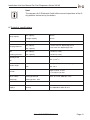
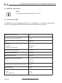
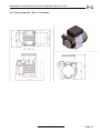
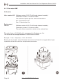
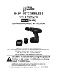
1
Installation And User Manual For Fuel Dispensers Series UNI 60
Installation and user manual for fuel
dispensers Series UNI 60
Responsable for the contents:
K + S ELEKTRONIK GmbH
Heinrich-Hertz-Straße 9
D-78052 VS-Villingen
Phone: +49 (0) 77 21 - 99 846 0
Fax: +49 (0) 77 21 - 99 846 66
[email protected]
www.k-s-elektronik.de
This documentation is protected by copyright. Neither the manual in full nor any part of
it may be extended, reproduced nor modified without the explicit written approval of
K+S ELEKTRONIK GmbH.
Development: Version 14.12.2007
© K + S ELEKTRONIK GmbH
© Copyright
Installation And User Manual For Fuel Dispensers Series UNI 60
1. Contents
2. Introduction
2.1
For the user
2.2
Safety instructions
2.3
Safety symbols
2.4
Additional important symbols at the fuelling station site
2.5
Basic safety instructions
2.6
Obligations of the operator
2.7
Compliance with instructions and regulations
2.8
Warranty
4
4
5
6
7
7
8
8
10
3. General product information
3.1
Overview
3.2
Technical data
3.3
Functional description
3.4
Description of components
3.5
Designation of components
3.6
Rating plates fuel dispenser
3.7
Explanations regarding the fuel dispenser rating plate
11
11
12
13
14
15
16
17
4. Transport, storage and unpacking
4.1
Transport
4.2
Storage
4.3
Unpacking
18
18
19
19
5. Installation
5.1
Safety instructions
5.2
Installation of the fuel dispenser
5.3
Foundation
5.3.1 Foundation plan single pump
5.3.2 Foundation frame single pump
5.4
Mechanical fuel dispenser mounting
5.4.1 Electric cables
5.4.2 Connection of the hydraulic unit
5.4.3 Electr. installation wiring
5.4.4 Underground tank
5.4.5 Above-ground tank
5.5
Fuel cable wiring
20
20
21
21
22
23
24
25
26
27
28
29
30
© K + S ELEKTRONIK GmbH
Page 1
Installation And User Manual For Fuel Dispensers Series UNI 60
6. Electr. power supply
6.1
Overvoltage protection
6.2
Uninterruptible power supply
6.3
Wiring of the fuel dispenser
6.4
Supply of the pumps
6.5
Data lines
6.6
Service lines
6.7
Trouble-free cable installation
31
31
31
32
33
33
34
34
7. Fuel
7.1
7.2
7.3
7.4
7.4.1
7.4.2
7.4.3
7.5
35
35
35
36
37
37
38
38
38
dispenser operation
Instructions for safe fuel dispenser operation
Putting the fuel dispenser into operation
Checking/changing the direction of rotation of the motor
Operation of the fuel dispenser
Fuel dispensing
Position of the nozzle
Operating mode of the fuel dispenser
Switching the fuel dispenser off
8. Maintenance and service
8.1
Instructions for maintenance
8.2
Maintenance of the housing
39
40
40
9. Technical specifications
9.1
Hydraulic components
9.1.1 Flow meter KME
9.1.2 Vane pumps PA 1, PA 2 - illustration
9.1.3 Flow meter KME
9.2
Flow meter KME
41
42
42
43
43
45
10. Fuel dispenser dimensions
10.1 Single pump
46
46
11. Hazardous areas
11.1 Wiring diagram
47
48
Page 2
© K + S ELEKTRONIK GmbH
Installation And User Manual For Fuel Dispensers Series UNI 60
12. Troubleshooting
12.1 Safety instructions
12.2 Malfunctions
12.2.1 Pump does not dispense fuel
12.2.2 Reduced or no fuel dispensing
12.3 After troubleshooting
49
50
50
51
52
13. Test certificates and other certificates
13.1 EC declaration of conformity
13.2 QMS certificate
53
53
54
© K + S ELEKTRONIK GmbH
Page 3
Installation And User Manual For Fuel Dispensers Series UNI 60
2. Introduction
2.1 For the user
About this
manual
This installation and user manual serves for providing the user with the
necessary information and instructions facilitating complete and effective installation, parameter setting, operation and maintenance of the fuel
dispenser series Uni 60. Therefore, read the corresponding chapters
prior to proceeding with the installation or operation of the fuel dispenser.
Observe all danger warnings and general instructions set out in this manual.
This manual has been carefully worked out by the manufacturer and is
an integral part of any fuel dispenser delivery according to the CE directive.
The manual is arranged in individual topic-related chapters and sections
and has a logical structure (learn - prepare - use - maintain).
The manual and any attached documents must be kept in a safe place
within reach during the whole service life of the fuel dispenser. Thus, it
also constitutes an information source for operation settings and error
elimination with regard to the fuel dispenser.
This manual reflects the technical state-of-the-art at the date of fuel dispenser sale or delivery.
This manual is subject to modifications and updates resulting from further developments.
Intended
use
The fuel dispensers of the series UNI 60 are designed to meet only the
requirements of an end user and for a maximum fueling capacity of
10,000 liters per month.
These fuel dispensers are only intended for the dispensing of the
following liquids other than water:
Diesel, biodiesel and fuel oil
Page 4
© K + S ELEKTRONIK GmbH
Installation And User Manual For Fuel Dispensers Series UNI 60
2.2 Safety instructions
General
The user is liable for the observance of the contents of this manual. Any
use contrary to the designated use described in this manual is not permitted. The user is solely responsible for any damage resulting from
such use.
The safety instructions are not only intended for assuring the own safety
but also for the protection of persons not involved against damage to
property and body. Safe operation of the fuel dispenser is hereby garanteed.
The “safety instructions" must be attached in the required size according to the regulations for hazardous substances “GefStoffV”.
The symbol shown (left-hand side) is used in this installation and user
manual in order to draw special attention to important information and
remarks.
© K + S ELEKTRONIK GmbH
Page 5
Installation And User Manual For Fuel Dispensers Series UNI 60
2.3 Safety symbols
The following symbols draw the attention to important special notes.
Attention!
This pictogram draws attention to legal regulations which must be complied with regarding assembly, commissioning and use of fuel dispensers.
Warning!
Non-observance of these requirements can lead to injury of
persons and/or damage to the fuel dispenser.
Caution - electric voltage!
Warning against touching electric lines and contacts. Non-observance
of these requirements can cause electric shock and lead to injury of
persons and damage to property.
Explosion hazard!
Special care is required in the case of spilled fuel. Inflammable vapours
may easily lead to explosion or deflagration. Therefore, such fuel must be
removed immediately by means of suitable absorbent means.
Electrostatically endangered components, ESD!
This means that any contact with the contact surfaces or electr.
components may lead to the destruction of the electronic control unit
and put the fuel dispenser out of service.
Page 6
© K + S ELEKTRONIK GmbH
Installation And User Manual For Fuel Dispensers Series UNI 60
2.4 Additional important symbols at the fuelling station site
Explosion hazard
No smoking
No mobile phones
No open fire
The “No mobile phones” sign is especially important if one uses the mobile phone while refuelling motor gasoline at the same time.
Deflagration may occur when activating the buttons.
2.5 Basic safety instructions
Protection and
safety devices
Any protection and safety devices must be checked regularly, but at the
latest when carrying our maintenance work.
They may never be bypassed or ignored.
Any removed safety and proection devices must be:
mounted again before putting into operation
checked for correct functioning.
Make sure that the safety devices at the installation site
(e.g. Emergency Stop button, fire fighting devices) are visible and
easily accessible.
© K + S ELEKTRONIK GmbH
Page 7
Installation And User Manual For Fuel Dispensers Series UNI 60
2.6 Obligations of the operator
Attention!
The fuel dispenser is a complex unit and must fulfill high requirements.
Therefore, the operator is obliged to carry out the following protection
measures and to observe the safety instructions.
Soiling
It is required to clean the tanks and pipes and to check whether the
fuel is pure (soiled filters in the fuel dispenser do not justify any repair
under warranty!) before putting the fuel dispenser into operation.
Power supply
Before putting the fuel dispenser into operation, the electric power
supply and the correct wiring must be checked in order to prevent
electric shocks and to ensure explosion protection (fuels are combustibles of class I).
Leakage
Even in case of minor leakage in the fuel dispenser, measures must be
taken to minimize the generation of vapours and to prevent escaping
fuel from entering into the soil. Leakage in the interior of the fuel dispenser must be checked via the exit hole located in the middle of the
front base.
Lighting
Ensure sufficient illumination of the refuelling area.
Out of operation
When not operated, the fuel dispenser must be protected against
unauthorized use.
2.7 Compliance with instructions and regulations
Overview
UVV - Accident prevention regulation
VdTÜV bulletin 651 “Electric equipment of fuelling stations”
TRbF - Technical rules for inflammable liquids
GefStoffV - Regulations for hazardous substances
VbF - Regulations for inflammable liquids
VAwS - Regulations for installations used for storage, filling and
handling of substances hazardous to water
VLwF - Regulations for the storage of liquids hazardous to water
VDE regulations
21. BimSchV - Regulations regarding the Federal Immission Control
Law
Page 8
© K + S ELEKTRONIK GmbH
Installation And User Manual For Fuel Dispensers Series UNI 60
ESD
Directives
Electro Static Discharge.
Under daily conditions, persons and tools may be electrostatically charged by friction. When touching electronic components, this charge may
lead to discharge and thus to destruction of the components or circuit
boards.
Therefore, this energy must be reduced by touching the protective
earth (metallic housing parts) before proceeding with any work in the
interior of the pump head.
The fuel dispensers are designed for use in business and industrial
areas and fulfill the requirements of the
EMC directive 89/336/EEC
Low-voltage directive 73/23/EEC
Machinery directive 98/37/EC
En DIN 13617-1:2004
Installation
instructions
To ensure compliance with the above mentioned directives during fuel
dispenser installation, you must:
observe the installation instructions described in this manual and make
sure that the metallic housing parts of the fuel dispenser and the
earthing conductor are connected to the same potential and no
compensation current may flow.
© K + S ELEKTRONIK GmbH
Page 9
Installation And User Manual For Fuel Dispensers Series UNI 60
2.8 Warranty
Important!
The company K + S grants a warranty for the fuel dispenser within the
scope of the “General Terms and Conditions (AGB)”.
Exclusion of
warranty
Warranty claims are void if one of the following points is not observed
and complied with:
Personnel
Any work as well as any interventions on the fuel dispenser require
special knowledge and may only be carried out by authorized
companies. The company K + S is not liable for any damage resulting
from incorrect maintenance or incorrect intervention.
Original spare parts
Any modifications of the fuel dispenser carried out without the explicit
approval of the manufacturer lead to the exclusion of all liability claims
towards the manufacturer. This also applies to the use of spare parts
which are not produced or released by the company K + S.
Delivery
Page 10
The correct functioning, safety and accuracy of each fuel dispenser are
checked in the factory. The fuel dispenser is delivered together with the
required approval certificates.
© K + S ELEKTRONIK GmbH
Installation And User Manual For Fuel Dispensers Series UNI 60
3. General product information
3.1 Overview
Manufacturer
K + S ELEKTRONIK GmbH
Fuel dispensers
System engineering
Pump electronics
Fuel data acquisition
Heinrich-Hertz-Straße 9
D-78052 VS-Villingen
Phone: +49 (0) 77 21 - 99 846 0
Fax: +49 (0) 77 21 - 99 846 66
Product
Fuel dispenser with liter counter or fuel terminal (Tankautomat),
not calibratable.
Product
designation
Fuel dispenser series Uni 60
© K + S ELEKTRONIK GmbH
Page 11
Installation And User Manual For Fuel Dispensers Series UNI 60
3.2 Technical data
Hydraulic
system
Capacity:
Min. capacity
50 l/min ***
Average capacity
70 l/min ***
Max. capacity
90 l/min ***
*** depending on the temperature and quality of the medium.
Dispens. tolerance: ± 0.50 % with min. dispensing of 2.0 l
Max. oper. pressure: 0.18 MPa (1.8 bar); 0.25 MPa (2.5 bar)
for 50, 70 and 90 liters.
Electric motor:
Single phase, 230 V, 370 W -1.5 A, 2800 rpm
Single phase, 230 V, 550 W - 4.0 A, 1400 rpm
Single phase, 230 V, 1050 W - 5.0 A, 1400 rpm
Electronic
liter counter
Fuel terminal
Liter counter: Power supply: 230 V; +10% -15%; 50 Hz ± 5 Hz
Power consumption: max. 50 VA
Operating temperature: - 25 to + 55 °C
Displays
LCD display with LED background illumination
Display for quantity
Character height quantity: 2.54 mm (1")
Separate description:
Liter counter: VC1
Fuel terminal: TDE 50
Page 12
© K + S ELEKTRONIK GmbH
Installation And User Manual For Fuel Dispensers Series UNI 60
3.3 Functional description
Housing
casings
The outer housing parts, such as doors, covers, etc., of the K+S fuel
dispensers of the UNI 60 series are made of zinc- and powder-coated
steel which is permitted for fuel dispensing applications.
Bearing parts
The bearing fuel dispenser parts are also made of powder-coated hotgalvanized steel with a thickness of 1.5 mm.
Color
Standard colors of the K+S fuel dispensers:
Combination of white aluminium (RAL9006), blue (RAL5005) and
black (RAL 9005).
Hydraulic unit
Each fuel dispenser is equipped with an hydraulic unit (monoblock +
flow meter). The pump used is a vane pump.
Encoder
The flow meter is equipped with a reliably operating singlel-channel
encoder.
Display “Liter” dispenser
The display of the fuel dispenser with liter counter shows the
quantity of dispensed fuel in liters.
Fuel terminal
The display of the fuel dispenser with fuel terminal shows the quantity dispensed and user information.
Hoses/
nozzle
The hoses are made of high-quality oil-resistant rubber
(shunt resistance 100 M-Ohm) and are fitted (standard equipment)
with an automatic nozzle.
© K + S ELEKTRONIK GmbH
Page 13
Installation And User Manual For Fuel Dispensers Series UNI 60
Important!
A complete fuel dispenser always comprises a liter counter or a fuel
terminal.
3.4 Description of components
Number of
pump points
The nozzle is the part of the fuel dispenser which allows the customer
to take the desired fuel.
The K+S fuel dispensers of the Uni 60 series have one pump point.
Fuel dispenser
orientation
The fuel dispensers can be used as a single pump, depending on the
orientation.
Number of products
With the series Uni 60, it is only possible to dispense 1 type of fuel.
Pump capacity
This is the max. fuel quantity which can be dispensed via the nozzle. It
is indicated in liters per minute.
Display types
A display version for company fuelling stations (liter display) is available. The liter display shows only the dispensed quantity in centiliter and
is used for fuel dispensers for, e.g., company fuelling stations.
Page 14
© K + S ELEKTRONIK GmbH
Installation And User Manual For Fuel Dispensers Series UNI 60
3.5 Designation of components
Display unit
Pump head
Rating plate
Panel
Hose connection
Nozzle boot
Cover sheet
Base
© K + S ELEKTRONIK GmbH
Page 15
Installation And User Manual For Fuel Dispensers Series UNI 60
3.6 Fuel dispenser rating plate
Umgebungs Temp. - 25°C ... + 55°C
_ 20°C
Medium Temp. <
Genauigkeitsklasse 0,5 Medium / Mineralöl
Mechanische Klasse M1
Elektromechanische Klasse E1
Hersteller
K+S Elektronik GmbH
Heinrich-Hertz-Str.9
D-78052 VS-Villingen
Type
Uni 60
Serial No. / Year
XXXX / XX
W&M Approval No.
Q max.
L/min.
50
Page 16
0
Q min.
L/min.
3
0
P max.
bar
V min.
L
4,0
2,0
© K + S ELEKTRONIK GmbH
Installation And User Manual For Fuel Dispensers Series UNI 60
3.7 Explanations regarding the fuel dispenser rating plate
Important!
The rating plate provides information about the manufacturer, serial
numbers and dispensing quantity of the fuel dispensers.
K+S Elektronik GmbH
Heinrich-Hertz-Str. 9
D-78052 VS-Villingen
Name and address of the manufacturer
M 07 0103
Fuel dispenser for diesel,
biodiesel and fuel oil
Scope of use of the dispenser
TYPE UNI 60
Designation of the fuel dispenser type
Qmax 50, 70, 90 (l/min)
Versions of hydraulic parameters
II 2G IIA T3
Marking of explosion-protected el. equipment:
Min. pump capacity
II 2 - equipment for rooms subject to explosion hazard other than mines; probability of creation of explosive atmosphere - danger zone 1
G - risk of explosion caused by gases or vapour
IIA - gas group - lowest group of risk
T3 - max. temperature of the el. equipment which
might cause ignition of the ambient atmospheree
(200°C)
© K + S ELEKTRONIK GmbH
Page 17
Installation And User Manual For Fuel Dispensers Series UNI 60
4. Transport, storage and unpacking
4.1 Transport
Safety
instructions
Dispatch method/
transport
Storage/
case of damage
The fuel dispenser and its individual components have been tested in the
manufacturer’s premises using a medium (e.g. spindle oil) which is not
classified as a hazardous material.
Therefore, the fuel dispenser is not subject to the strict regulations for
“hazardous materials transportation” when being delivered.
The customer shall agree the method of dispatch with the manufacturer. If
the company K+S is responsible for dispatch, the product will be delivered
to the corresponding place of destination (place of installation).
The manufacturer has adequate knowledge of proper packing,
loading and transportation. Therefore, the fuel dispenser is bolted to a
special transport pallet and protected against external influences by its
eco-friendly packing.
Should the customer desire another method of dispatch, the
manufacturer shall provide professional loading, but is not liable for the
method of transportation.
Warning!
When transporting the dispenser, only lift trucks may be used. K+S is not
liable for possible damage if other handling devices are used.
Observe the following for transportation:
The warning instructions on the information sheet included
The total weight and the dimensions of the dispenser
The vertical position of the dispenser. A horizontal position may damage the outer casing.
Sufficient fastening on the vehicle. Fasten the dispenser so that it cannot move or tilt over.
Important!
During transportation, make sure that the environmental conditions (e.g.
storage temperature) are complied with.
If, despite the proper packing, a damage occurs, the company K+S
must be contacted immediately.
Page 18
© K + S ELEKTRONIK GmbH
Installation And User Manual For Fuel Dispensers Series UNI 60
4.2 Storage
Important!
When storing the dispenser for an interim period, K+S recommends to
store the dispenser in locations protected against fire and weather
influences in order to protect the transport and packing material.
4.3 Unpacking
Important!
The transport and packing material can be used several times for reasons of environmental protection. Therefore, it should be handled carefully and returned to K+S.
© K + S ELEKTRONIK GmbH
Page 19
Installation And User Manual For Fuel Dispensers Series UNI 60
5. Installation
5.1 Safety instructions
Important!
During installation, special attention must be paid to the safety symbols
and their meaning described in chapter 2.3.
Furthermore, the following must be complied with:
The regulation regarding inflammable liquids (VbF)
The technical rules regarding inflammable liquids (TRbF)
The Water Resources Act (WHG)
EU and VDE directives.
Personnel
The fuel dispensers may only be installed by staff qualified and (authorizued fuelling installation and fuelling station constructors) pursuant to
relevant standards, regulations, local regulations and the instructions in
this manual.
Smoking/
open fire
Smoking and open fire are prohibited in the complete vicinity of the
dispenser.
Fuel/diesel
Adhere to the handling instructions for fuel and diesel.
Leaks
Check the fuel dispenser for leaks. Should you establish fuel leaks, disconnect the power supply line and contact the technical service.
Electr. connection
The electr. connections must be carried out by qualified personnel.
Lightning protection
A sufficient protection for the prevention of static charges and lightning
strokes must correspond to the regulation TRbF.
Fire extinguisher
Make sure that an operative fire extinguisher is available.
Protective aids
When handling the device, use suitable protective aids.
Page 20
© K + S ELEKTRONIK GmbH
Installation And User Manual For Fuel Dispensers Series UNI 60
5.2 Installation of the fuel dispenser
First, check the place of installation of the dispenser.
Place of installation
The so-called range of action of the nozzle (hose length plus one meter) must comply with the requirements given under "Important!".
Installation below ground level is prohibited!
All water drains must be provided with oil separators according to DIN.
Hazardous zones around the fuel dispenser are specified according
to EN 60079-10.
5.3 Foundation
Local
requirements
Important!
A foundation is required for the installation of the fuel dispenser. The local conditions determine the installation height and the required foundation. If necessary, this must be clarified on the site by an architect and
the owner of the fuelling station.
© K + S ELEKTRONIK GmbH
Page 21
Installation And User Manual For Fuel Dispensers Series UNI 60
5.3.1 Foundation plan
Page 22
© K + S ELEKTRONIK GmbH
Installation And User Manual For Fuel Dispensers Series UNI 60
5.3.2 Foundation frame single pump
Order no. for
single pump
The foundation frame is not included in the standard delivery and must
therefore be ordered separately. See price list.
© K + S ELEKTRONIK GmbH
Page 23
Installation And User Manual For Fuel Dispensers Series UNI 60
5.4 Mechanical fuel dispenser mounting
Mounting
The foundation frame is seated into concrete. The front and rear fuel dispenser casings must be removed in order to fasten the fuel dispenser.
The fuel dispenser is placed on the foundation frame and fixed by the
screws included in the delivery.
Important!
K+S recommends installation of the fuel dispensers on islands to make
sure that the moving direction of the vehicles is not important.
The dispenser orientation depends on the moving direction of the
vehcile.
Distance dispenser
and tank
A maximum distance of 3.0 meters between the dispensers and
the fuel tanks is recommended. Non-observance of this requirement
may cause that the fuelling operation is hindered and the pump capacity (flow) is reduced. All technical requirements for fuelling stations
must be complied with by the manufacturer of the fuel dispensers.
Distance dispenser
and wall
To ensure free access during cleaning and repair work, a distance of at
least 1 m between the wall or building must be observed.
Fuel tanks
Dispensers can be connected to both, underground and aboveground tanks. The steel housing must be placed on the base aligned
in concrete. There, the lines leading from the tanks to the dispensers
must be connected.
The supply lines leading to the dispenser must have good insulating
properties to prevent inflammable liquids or vapours from entering into
the fuel dispenser.
Page 24
© K + S ELEKTRONIK GmbH
Installation And User Manual For Fuel Dispensers Series UNI 60
5.4.1 Electric cables
In addition to the grounding connection, the following lines must be connected in the base below the fuel dispenser:
Power supply of the calculator and the switching circuits,
three-wire cable NYYÖ-I 3 x 2.5
Data line - shielded eight-wire cable AYSTÖE 8 x 0.75
Additional data line, e.g. level monitoring
© K + S ELEKTRONIK GmbH
Page 25
Installation And User Manual For Fuel Dispensers Series UNI 60
5.4.2 Connection of the hydraulic unit
Connection
hydr. unit to
suction line
Page 26
The corrugated pipe is connected to the suction line
Observe the correct position of the gasket seals
All recesses and outlets at the foundation frame must be sealed
© K + S ELEKTRONIK GmbH
Installation And User Manual For Fuel Dispensers Series UNI 60
5.4.3 Electr. installation wiring
L1 N PE
L1 N PE
PE
Power
Netzteil
supply
24V
unit
24V
Zapfsäulenkopf
Pump
head
230 V
Motor
Motor
© K + S ELEKTRONIK GmbH
Page 27
Installation And User Manual For Fuel Dispensers Series UNI 60
5.4.4 Underground tank
Connection to an
underground tank
When connecting the fuel dispenser to an underground tank, the
check valve must be installed in the suction line. It is intended to
prevent an interruption when refuelling and the air inlet when starting
the refuelling operation. The separate check valve must not be installed if a check valve is already installed in the inlet funnel.
Fuel dispenser installation - underground tank
Page 28
© K + S ELEKTRONIK GmbH
Installation And User Manual For Fuel Dispensers Series UNI 60
5.4.5 Above-ground tank
Connection above- When connecting the fuel dispenser to an above-ground tank, the
ground tank
ball valve must be installed in the suction line for safety reasons.
Thus, a negative pressure of approx. -0.03 Mpa of the pump is guaranteed. The ball valve must be installed at the lowest point in the line.
These valves must be closed by the fuelling station operator if the fuel
dispenser is out of operation. If these valves are not installed, fuel leaks
may be caused.
Fuel dispenser installation - above-ground tank
Table - legend for illustration underground tank and above-ground tank
Pos.
Description
Pos.
Description
1
Fuel dispenser
6
Not required
2
El. power supply cable and
data line
7
Inlet funnel (without check
valve)
3
Not required
8
Fuel tank
4
Not required
9
Not required
5
Suction line
10
Ball valve
© K + S ELEKTRONIK GmbH
Page 29
Installation And User Manual For Fuel Dispensers Series UNI 60
5.5 Fuel cable wiring
Cable wiring
Page 30
The company K+S recommends laying the cables according to the
standard, i.e. a separate line leading into the fuel tank.
It is possible to connect several fuel dispensers (pumps) to the main
line, i.e. several fuel dispensers (pumps) can be connected to one single supply line.
The company K+S, manufacturer of fuel dispensers, does not recommend this type of connection due to possible fluctuations when suctioning fuel from the tank.
© K + S ELEKTRONIK GmbH
Installation And User Manual For Fuel Dispensers Series UNI 60
6. Electr. power supply
6.1 Overvoltage protection
Important!
An overvoltage caused by lightnings at a distance of several kilometers
or by industrial activities can occur in all lines. The pulses generated by
lightnings may destroy the complete electronics. For this reasons, an
overvoltage protection is used in most countries leading the overvoltage
energy to the grounding connection thus protecting the electronics.
Therefore, the fuel dispenser manufacturer recommends protecting the
main switch cabinet (and/or the secondary switch cabinet), supplying
the fuel dispenser and the electronics (PC, POS, etc.) by means of an
overvoltage protection and lightning arresters.
6.2 Uninterruptible power supply
UPS
Important!
In order to ensure trouble-free operation of fuel dispensers, it is necessary to secure the stabilized fuel dispenser feeding by an uninterruptible
power supply UPS.
Current interruptions, heavy disturbances or voltage drops in peak hours
(particularly during winter time) are very frequent phenomena in the power supply network. All these phenomena can be eliminated by the use
of a correct uninterruptible power supply (UPS). There are two types of
UPS available and suitable for the fuel dispenser: UPS offline and UPS
online.
UPS (offline) is sufficient for the stabilization in the filling stations conbnected to a very stable power supply network (without any voltage drop
and any disturbances). In other cases, the online version of UPS must be
used. Disturbances, voltage drops or failures can result in frequent blokking of the dispensers, problems in the computer/dispenser communication, failures of computers (data loss), etc.
© K + S ELEKTRONIK GmbH
Page 31
Installation And User Manual For Fuel Dispensers Series UNI 60
In addition to the grounding connection, the following lines must be layed in the base below the fuel dispenser:
Power supply of the calculator and switching circuits,
three-wire cable NYYÖ-I 3 x 2.5
Data line - shielded eight-wire cable AYSTÖE 8 x 0,75
Additional data line for, e.g. level monitoring
6.3 Wiring of the fuel dispenser
Important!
The electr. wiring of the K+S fuel dispensers requires protection against
electric shocks.
All fuel dispensers in the filling station must be interconnected to the
grounding network via the grounding electrode. The yellow and green
conductor, section of min. 4 mm 2, or a special cable can be used as
grounding electrode. The grounding electrode must be connected to the
grounding terminal of the fuel dispenser placed on the foundation
(screw M 8), MARKED correspondingly.
All electr. lines must resist to fuel vapours and have good insulating properties because they are subject to aggresive explosion-hazardous environments for a long period.
All cable ends entering the fuel dispenser must be long enough to facilitate installation (cable end in the pump head). The cable ends must
have a min. length of 2.0 m above foundation.
Page 32
© K + S ELEKTRONIK GmbH
Installation And User Manual For Fuel Dispensers Series UNI 60
6.4 Supply of the pumps
Important!
The supply of the electr. pump motors of all fuel dispenser models is realized via a five-wire cable NYYÖ-I 3 x 2.5. In the switch cabinet, the cable is connected to fuses and switches. The individual pump motors are
controlled via switches in the fuel dispenser.
6.5 Data lines
The data line serves for remote fuel dispenser control in the so-called
automatic mode (i.e. the fuel dispenser is controlled remotely by the
console or the computer). The line is not required if the dispenser is
operated in the manual mode only.
For the data line, at least a shielded eight-wire data line with a min. section of 0.75 mm2 must be used!! The cable sheath must be made of flame resistant and fuel vapour-resistant material. The shielded eight-wire
cable AYSTÖE 8 x 0.75 can be used as data line. The cable is led from
the operator’s workplace in the kiosk into the fuel dispenser.
© K + S ELEKTRONIK GmbH
Page 33
Installation And User Manual For Fuel Dispensers Series UNI 60
6.6 Service lines
Service lines serve for special purposes. These lines are not required
for the operation of the fuel dispenser. They are used in order to remotely control certain fuel dispenser functions or to send certain signals
from the fuel dispenser. In order to decide whether a service line is required, you must always contact the personnel of the company K+S
Elektronik GmbH.
6.7 Trouble-free cable installation
Important!
To ensure correct operation of the fuel dispenser, die signal lines of the
fuel dispensers must be separated correctly from the power supply lines. Parallel connection of the power supply lines and signal lines without separation results in disturbances and undesirable parasite phenomena which may cause problems of the fuel dispenser control and/or
complete destruction of the electronics in the fuel dispenser and in the
kiosk. Therefore, any crossing or parallel laying (in a single bundle) of
the signal and power cables has to be avoided in any case. Separate
cable channels (e.g. metal tubes) for power and signal cables represent
a suitable solution.
The manufacturer is not liable for damage caused by unsuitable
laying and wiring of cables/lines!
Page 34
© K + S ELEKTRONIK GmbH
Installation And User Manual For Fuel Dispensers Series UNI 60
7. Fuel dispenser operation
7.1 Instructions for safe fuel dispenser operation
Important!
The fuel dispenser is a complex system which must fulfill a number of
demanding functions. Prior to putting the fuel dispenser into operation, it
is necessary to clean the tanks and lines and to check whether the fuel
is pure. For putting the fuel dispenser into operation, the electr. power
supply and the correct wiring must be checked to prevent electric shock
and to provide fire safety.
Prohibited!
Smoking in the vicinity of the dispenser
Open fire in the filling station area
Use of a mobile in the vicinity of the dispenser
Dispensing while the engine is running
7.2 Putting the fuel dispenser into operation
Important!
Switching the fuel dispenser on and off is carried out in the master
switch cabinet of the filling station where the fuel dispensers are
connected. Each fuel dispenser has three power supply outlets with
protection switches in the master switch cabinet:
Supply of the electr. pumps
Supply of the electronic fuel dispenser calculator (230 VAC stabilized)
© K + S ELEKTRONIK GmbH
Page 35
Installation And User Manual For Fuel Dispensers Series UNI 60
Recommendation
Page 36
Switch the fuel dispenser on as follows:
Switch on the 230 V protection switch for stabilized supply of the electronic fuel dispenser calculator (all display segments are tested automatically and the values of the last fuelling operation are displayed).
© K + S ELEKTRONIK GmbH
Installation And User Manual For Fuel Dispensers Series UNI 60
7.3 Operation of the fuel dispenser
Attention!
The owner of the filling station is liable for its operation.
He must supervize fuelling operations and instruct the customer regarding correct use of the fuel dispenser in case of improper use. The owner must mark the dangerous zone of the filling station by means of appropriate symbols (smoking prohibited, no open fire, driving direction,
etc.). The operating manual of the filling station and/or information about
the general obligations must be accessible to the customer.
7.4 Fuel dispensing
Data storage
Note!
The fuel dispenser is activated by removing the nozzle from the nozzle
boot. The integrated contact releases the liter counter/price calculator
which is automatically reset to zero. The pump motor starts and the
fuelling operation begins. The fuel flows by pressing the nozzle and
stops by releasing the nozzle. The user must place the nozzle back into
the nozzle boot. Thus, the valve contact interrupts the power supply of
the pump motor. The dispensed quantity remains displayed on the liter
counter until the nozzle is operated again.
With the autofuel terminal, the quantity and the unit price are saved for
a period of 90 days for fiscal reasons.
In the case of self-service filling stations, nozzles with locking are used.
The flow is controlled via the locking lever. In the basic version, the nozzle
is supplied with lever locking. To activate the lever locking, it must be
pressed during the fuelling operation. When releasing the lever or the
nozzle drops out of the filler neck, the flow is stopped. The stop function is
activated as soon as the tank is full (overlow sensor). The fuelling operation is stopped even if the locking lever is still pressed. The safety function
is also activated in case of improper use of the nozzle, e.g. if the nozzle
deviates by more than 15 degrees from the horizontal plane, the flow is
stopped (even if the operating lever is pressed). After activation of the
stop and safety function, the locking lever must be released.
© K + S ELEKTRONIK GmbH
Page 37
Installation And User Manual For Fuel Dispensers Series UNI 60
7.4.1 Position of the nozzle
Correct position of the nozzle during fuelling.
The nozzle is in a vertical position; the valve does not block the air supply and the fuel can flow.
Incorrect position of the nozzle.
The nozzle swivels and is no longer in a horizontal position. The valve
blocks the air supply and the fuel supply.
7.4.2 Operating mode of the fuel dispenser
Attention!
Before switching the automatic mode to the manual mode, the service
technician must be contacted.
7.5 Switching the fuel dispenser off
Remark!
Switch the fuel dispenser off as follows:
1. Switch off the 230 V protective switch for the stabilized supply of the
electronic fuel dispenser calculator
2. Switch off the uninterruptible power supply UPS in the kiosk via the
switch located on the console (the yellow indicator lamp of the USP
goes off)
Page 38
© K + S ELEKTRONIK GmbH
Installation And User Manual For Fuel Dispensers Series UNI 60
8. Maintenance and service
Attention!
Prior to starting any maintenance work on mechanical, hydraulic or
electric parts/components, it is always necessary to disconnect the fuel
dispenser from the power supply source and to protect it from re-connection.
Note!
Do not remove the casings of the fuel dispenser during operation.
© K + S ELEKTRONIK GmbH
Page 39
Installation And User Manual For Fuel Dispensers Series UNI 60
8.1 Instructions for maintenance
Instructions for fuel dispenser maintenance
Maintain all fuel dispenser components clean so that possible unforeseeable faults can be dientified easily and removed quickly.
Check all connection elements systematically and, in case of fuel leaks, retighten the connection elements and/or seal them.
Check and tighten the screws by means of which the electr. motor and
the pump are fastened on the console.
Check the condition of the nozzles and decide its repair or
replacement, depending on the revealed defect.
Check the correct functioning of the door locks and the nozzle boot.
Regularly check the tank for oil residues/mud, water residues and
other impurities and clean.
8.2 Maintenance of the housing
Housing
Page 40
Note!
Parts of the fuel dispenser housing are made of powder and zinc-coated steel or stainless steel. These parts need regular maintenance, particularly during the winter season, because aerosols of chloride preparations arisen from the salts used for road maintenance can result in
permanent damage to lacquers of untreated body parts and/or to intercrystalline corrosion. Pay attention to the corrosion of guards. Use water
and/or solutions of detergents and available car care products for the
regular maintenance of the fuel dispenser housing.
© K + S ELEKTRONIK GmbH
Installation And User Manual For Fuel Dispensers Series UNI 60
Note!
The company K+S Elektronik GmbH offers annual inspections of the filling stations carried out by its dealers.
9. Technical specifications
Min. capacity
50 l/min
Average capacity
70 l/min
Max. capacity
90 l/min
Min. capacity
± 0.25% with min. dispensing of 2.0 l
Max. capacity
± 0.5% with min. dispensing of 3.0 l
Max.
Min. capacity
0.18 MPa (1.8 bar)
operating pressure
Max. capacity
0.25 MPa (2.5 bar)
Pump capacity
Pumping tolerance
Viscosity of the
Max. 21 mm2 sfuel
Recommended
1.0 m (to achieve the nom. capacity)
Max.
Max. 2.0 m
Suction height
Single channel, 5 VDC
Encoder
1 x 35 imp/rev. per liter
Electr. motors
Tuthill type MEC80
(fuel pump)
Tuthill type PA 1, PA 2
Displays
Quantity
230 V; 0.37 kW, 2800 rpm, 2.5 A
From 0000.00 to 9999.99 l/min
© K + S ELEKTRONIK GmbH
Page 41
Installation And User Manual For Fuel Dispensers Series UNI 60
9.1 Hydraulic components
Note!
Vane pump: hydraulic pump type PA 1, PA 2
9.1.1 Flow meter KME
The KME flow meter is compatible with the PA 1, PA 2 pumps. It is used as a “measuring instrument” for accurate and reliable measurement of “liquids other than water”.
Dispensing volume per rev.
0.5 l
Diameter connection shaft encoder
10 mm
Rotation direction connection shafte encoder (top
view)
Clockwise
Dimensions
Horizontal
200x220 mm
Vertical (incl. drive pulley)
197 mm
Diameter measuring cylinder
72.4 mm
Durchmesser Antriebswelle
14,93 mm
Stroke (pistons 2 and 4)
29.86 mm
Stroke (pistons 1 and 4), adjustable
from
28.35 mm
to
31.39 mm
Minimum mechanical adjusting device increment
0.05 %
Working pressure
3.5 bar
Flow rate capacity +/- 0.3%
Q min.
2 l/min
Q max. (objective)
80 l/min
Page 42
© K + S ELEKTRONIK GmbH
Installation And User Manual For Fuel Dispensers Series UNI 60
9.1.2 Vane pump PA 1, PA 2 - illustration
© K + S ELEKTRONIK GmbH
Page 43
Installation And User Manual For Fuel Dispensers Series UNI 60
9.1.3 Flow meter KME
Calibration
Liter counter VC 1 Software version 30.35 (Tuthill single-channel encoder )
Parameter number 31 in service mode
The number of pulses per liter can be entered here.
Min.: 27 pulses per liter
Max.: 36 pulses per liter
Fuel terminal
TDE 50
Software version 40.35 (Tuthill single-channel encoder )
Parameter number 21 in service mode
The pulse factor (correction value) can be entered here.
The pulse factor is 0.034480 which corresponds to 29 pulses per liter.
The factor can be changed between 0.025000 and 0.039000.
Example: 1 liter = 30 pulses = 1/30 = 0.033333
Reason for the number input: Since the fuel terminal is fitted with a keypad, direct input
is possible without the need for complicated conversions.
Page 44
© K + S ELEKTRONIK GmbH
Installation And User Manual For Fuel Dispensers Series UNI 60
9.2 Flow meter KME
© K + S ELEKTRONIK GmbH
Page 45
Installation And User Manual For Fuel Dispensers Series UNI 60
10. Fuel dispenser dimensions
10.1 Single pump
Page 46
© K + S ELEKTRONIK GmbH
Installation And User Manual For Fuel Dispensers Series UNI 60
11. Hazardous areas
Ill. drawing assignment of explosion-protected zones according to EN 13617-1
Pos.
Description
Pos.
Description
0
Zone 2
3
Zone not subjet to danger of explosion (IP54)
1
Zone 1
4
Vertical division - type 1 (detail)
2
Zone 0
5
Explosion-protected cable connection EEx e II (IP67)
© K + S ELEKTRONIK GmbH
Page 47
Installation And User Manual For Fuel Dispensers Series UNI 60
11.1 Wiring diagram
Terminal
designation
Liter counter
Pump head
Data line
Page 48
© K + S ELEKTRONIK GmbH
Installation And User Manual For Fuel Dispensers Series UNI 60
12. Troubleshooting
12.1 Safety instructions
Before starting the elimination of any failures of a defective fuel dispenser, the following safety instructions must be complied with.
Warning!
Any intervention regarding the elimination of errors and repair of a defective fuel dispenser requires special knowledge. This work may be
carried out only by trained pesonnel and authorized companies.
Dangerous voltage!
Prior to starting any work on the electr. supply of fuel dispenser components, it is always necessary to disconnect the fuel dispenser from the
power supply source and to protect it against re-connection!
ESD!
When carrying out any work on electronic components, e.g. replacing
the control electronics, first touch grounded metal parts. Thus, any possible charges are discharged.
© K + S ELEKTRONIK GmbH
Page 49
Installation And User Manual For Fuel Dispensers Series UNI 60
12.2 Malfunctions
12.2.1 Pump does not dispense fuel
Failure
Cause of the failure
Elimination
Motor not running
Power supply failure
First, check all fuses, switches and
motor protection switches in the
switch cabinet as well as the connection cables for:
the fuel dispenser
- motor
- nozzle contact
- cable connection
- junction box
the price calculator
- check fuses
- check for short-circuit
- check contactor
Motor defective
Replace the defective motor
Page 50
© K + S ELEKTRONIK GmbH
Installation And User Manual For Fuel Dispensers Series UNI 60
12.2.2 Reduced or no fuel dispensing
Failure
Cause of the failure
Elimination
Pipings,
hydraulic connections
Suction line not tight
Seal suction lines
Check screw connections for
tightness, retighten if necessary
If required, replace defective
seals
Motor drive
Uneven running, generation of noise
Remove oil deposits
Pump
Sluggish pump drive
Check for wear and excessive
backlash
Contact technical service!
Dispensed fuel volume
too low
Soiled filter
Clean all suction and outlet filter
strainers, replace, if necessary
Flow meter
Sluggish
When the pump operates at high
capacity, replace the flow
meter
Contact technical service!
Nozzle
The fuel does not flow
while the nozzle is released
Restrainer soiled, etc.,
valve cone and seat
blocked due to fuel
deposits
Replace nozzle
Contact technical service!
© K + S ELEKTRONIK GmbH
Page 51
Installation And User Manual For Fuel Dispensers Series UNI 60
12.3 After troubleshooting
Important!
Mount again all casing covers after maintenance and repair work and
close the pump head. Check all loosened screw connections for tight
seat.
Carry out recommissioning only according to the relevant instructions.
Take the necessary measures to ensure that the fuel dispenser is only
operated in a safe and functional state.
Carry out a test run!
Attention!
After any intervention on the hydraulic installation, the volume rate must
be checked.
Page 52
© K + S ELEKTRONIK GmbH
Installation And User Manual For Fuel Dispensers Series UNI 60
13. Test certificates and other certificates
13.1 EC declaration of conformity
EG-Konformitätserklärung
EC - Declaration of Conformity
EC - Declaration de Conformité
Wir
We
Nous
K + S Elektronik GmbH
Anschrift
Address
Heinrich-Hertz-Straße 9
D-78052 VS-Villingen
erklären, dass das Produkt mit der Bezeichnung, Typ, Modell:
declare, that the product with name, type, model:
déclarons, que le produit nom, type, modèle:
Kraftstoffzapfsäule Serie Uni 60
mit den Anforderungen der Normen und Richtlinien
fulfils the requirernents of the standards and regulations of the Directive
satisfait aux exigences des normes et directives
Maschinen-Richtlinie 98/37/EG, 1998
EN 292-1/2 Sicherheit von Maschinen
EN 60204-1 Elektrische Ausrüstung von Maschinen
Niederspannungs Richtlinie 73/23/EWG
EMV-Richtlinie 89/336/EWG
EN 55011 (1998) + A1 (1999) + A2 (2002), Limit Class: B
EN 61000-3-2 (2006-04)
EN 61000-3-3 (1995-01) + A1 (2001-06) + A2 (2005-11)
EN 61000-4-2 (2001)
EN 61000-4-3 (2001)
EN 61000-4-4 (2001)
EN 61000-4-6 (2001)
EN 61000-4-11 (2001)
und den Prüfberichten übereinstimmt und damit den Bestimmungen entspricht.
and the test reports and therefore corresponds to the regulations of the Directive.
et les rapports d'essais et, ainsi, correspond aux règlements de la Directive.
Ort und Datum der Ausstellung:
Place and date of issue:
Lieu et date d'établissement:
VS-Villingen, den 08. Februar 2009
Name und Unterschrift des Befugten:
Name and signature of the authorised persons:
Nom et signature des personnes autorisées:
© K + S ELEKTRONIK GmbH
Leitung Entwicklung
Page 53
Installation And User Manual For Fuel Dispensers Series UNI 60
13.2 QMS certificate
Page 54
© K + S ELEKTRONIK GmbH