1
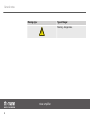
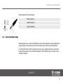
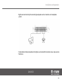
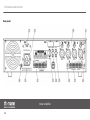
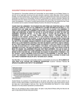
SA 125 CD
mixer amplifier
user manual
Musikhaus Thomann e. K.
Treppendorf 30
96138 Burgebrach
Germany
Telephone: +49 (0) 9546 9223-0
E-mail: [email protected]
Internet: www.thomann.de
14.09.2012
Table of contents
Table of contents
1
General notes............................................................................................................................................... 4
2
Safety notes.................................................................................................................................................. 7
3
Features....................................................................................................................................................... 13
4
Installation and operation.................................................................................................................. 14
4.1 Pin assignment.................................................................................................................................. 14
4.2 Screw terminal strips....................................................................................................................... 17
5
Connectors and controls...................................................................................................................... 20
6
Technical data........................................................................................................................................... 27
7
Protecting the environment.............................................................................................................. 29
SA 125 CD
3
General notes
1
General notes
This user manual contains important information on safe operation of the device. Read and
follow all safety notes and all instructions. Save this manual for future reference. Make sure
that it is available to all persons using this device. If you sell the device to other users, be sure
that they also receive this manual.
Our products are subject to a process of continuous development. We therefore reserve the
right to make changes without notice.
Symbols and signal words
This section provides an overview of the symbols and signal words used in this user manual.
mixer amplifier
4
General notes
Signal word
Meaning
DANGER!
This combination of symbol and signal word
indicates an immediate dangerous situation
that will result in death or serious injury if it is
not avoided.
CAUTION!
This combination of symbol and signal word
indicates a possible dangerous situation that
can result in minor injury if it is not avoided.
NOTICE!
This combination of symbol and signal word
indicates a possible dangerous situation that
can result in material and environmental
damage if it is not avoided.
Warning signs
Type of danger
Warning – high-voltage.
SA 125 CD
5
General notes
Warning signs
Type of danger
Warning – danger zone.
mixer amplifier
6
Safety notes
2
Safety notes
Intended use
This device is intended to be used for amplification, mixing and playback of signals from
musical instruments and microphones. Use the device only as described in this user manual.
Any other use or use under other operating conditions is considered to be improper and may
result in personal injury or property damage. No liability will be assumed for damages resulting
from improper use.
This device may be used only by persons with sufficient physical, sensorial, and intellectual
abilities and having corresponding knowledge and experience. Other persons may use this
device only if they are supervised or instructed by a person who is responsible for their safety.
SA 125 CD
7
Safety notes
Safety
DANGER!
Danger for children
Ensure that plastic bags, packaging, etc. are disposed of properly and are not
within reach of babies and young children. Choking hazard!
Ensure that children do not detach any small parts (e.g. knobs or the like) from
the unit. They could swallow the pieces and choke!
Never let children unattended use electrical devices.
DANGER!
Electric shock caused by high voltages inside
Within the device there are areas where high voltages may be present. Never
remove any covers.
There are no user-serviceable parts inside.
mixer amplifier
8
Safety notes
DANGER!
Electric shock caused by high voltages at the power amplifier output
The output voltages of modern high-performance amplifiers may result in death
or serious injury.
Never touch the bare ends of loudspeaker cables when the amplifier is on.
DANGER!
Electric shock caused by short-circuit
Always use proper ready-made insulated mains cabling (power cord) with a pro‐
tective contact plug. Do not modify the mains cable or the plug. Failure to do so
could result in electric shock/death or fire. If in doubt, seek advice from a regis‐
tered electrician.
SA 125 CD
9
Safety notes
CAUTION!
Possible hearing damage
With loudspeakers or headphones connected, the device can produce volume
levels that may cause temporary or permanent hearing impairment.
Do not operate the device permanently at a high volume level. Decrease the
volume level immediately if you experience ringing in your ears or hearing
impairment.
NOTICE!
Risk of fire
Do not block areas of ventilation. Do not install the device near any direct heat
source. Keep the device away from naked flames.
mixer amplifier
10
Safety notes
NOTICE!
Operating conditions
This device has been designed for indoor use only. To prevent damage, never
expose the device to any liquid or moisture. Avoid direct sunlight, heavy dirt, and
strong vibrations.
NOTICE!
Power supply
Before connecting the device, ensure that the input voltage (AC outlet) matches
the voltage rating of the device and that the AC outlet is protected by a residual
current circuit breaker. Failure to do so could result in damage to the device and
possibly injure the user.
Unplug the device before electrical storms occur and when it is unused for long
periods of time to reduce the risk of electric shock or fire.
SA 125 CD
11
Safety notes
NOTICE!
Possible damages by using an external battery
Improper handling may cause an arc or short circuit between the bare ends of a
live power cable to an external battery. This can destroy the battery and there is a
fire hazard!
If you use an external battery for power supply, connect the power cord to the
screw terminal on the rear panel first. Then connect the free ends of the cables to
the battery poles. Pay attention to the polarity marking! To disconnect the bat‐
tery, unscrew the cables on the battery first, then on the terminals of the device.
Also pay attention to the safety instructions of the battery manufacturer.
mixer amplifier
12
Features
3
Features
n
n
n
n
n
n
n
n
Built-in CD player
4 microphone/line inputs
24 V phantom powering
Priority function
AUX input, LINE output
Input for external pre-amplifier
Output for external power amplifier
Screw terminals for loudspeakers, telephone system and mains-independent voltage
supply
SA 125 CD
13
Installation and operation
4
Installation and operation
Unpack and check carefully there is no transportation damage before using the unit. Keep the
equipment packaging. To fully protect the device against vibration, dust and moisture during
transportation or storage use the original packaging or your own packaging material suitable
for transport or storage, respectively.
Establish all connections as long as the unit is switched off. Use the shortest possible highquality cables for all connections.
4.1 Pin assignment
You may use XLR connectors with either balanced or unbalanced pinout. Below you will find
an overview of the different options.
mixer amplifier
14
Installation and operation
XLR connectors for signal inputs
Balanced female XLR panel connectors are used for the signal inputs. The figures and tables
show the XLR pin assignment.
Balanced pinout:
1
Ground, shielding
2
Positive signal (+)
3
Negative signal (–)
Unbalanced pinout:
1
Ground, shielding
2
Signal
3
Jumpered with pin 1
SA 125 CD
15
Installation and operation
Jack plugs for signal inputs
The figures and tables show the pin assignments of the ¼ inch (6.35 mm) jack plugs.
Unbalanced pinout of mono jack plug:
1
Signal
2
Ground, shielding
Unbalanced pinout of stereo jack plug:
1
Signal
2, 3
Ground, shielding
mixer amplifier
16
Installation and operation
Balanced pinout of stereo jack plug:
1
Positive signal (+)
2
Negative signal (–)
3
Ground, shielding
4.2 Screw terminal strips
All loudspeaker units as well as the telephone system and the battery for mains-independent
voltage supply are connected via two screw terminal strips on the rear side of the device.
First detach the covers of the screw terminal strips using a suitable screwdriver. Loosen the
required screw terminals (see connection diagrams) and attach the necessary cables using a
suitable screwdriver.
SA 125 CD
17
Installation and operation
Left screw terminal strip for connecting a battery for mains-independent voltage supply and
loudspeaker units:
mixer amplifier
18
Installation and operation
Right screw terminal strip for connecting loudspeaker units or monitors and a telephone
system:
Finally check all cable connections for tightness and reattach the terminal screw strip covers to
the device.
SA 125 CD
19
Connectors and controls
5
Connectors and controls
Front panel
mixer amplifier
20
Connectors and controls
1 CD drive.
2 “Stop” button for stopping playback.
3 “Back” button for jumping to the previous track.
4 “Forward” button for jumping to the next track.
5 “Volume +” button.
6 “Eject CD” button.
7 USB port for external audio equipment.
8 + 9 LCD display with track and time information.
10 “Pause” button for pausing playback.
11 [CD/USB] button for switching between CD and USB device playback.
12 “Loop” button for playing tracks in a loop.
13 “Volume –” button.
SA 125 CD
21
Connectors and controls
14 Power on/off button for CD drive.
15 INPUT 1 – 4
Volume controls for inputs 1 to 4.
16 AUX
Volume control for the AUX input.
17 BASS
Control for boosting/cutting the low frequencies. Starting from the neutral position, turn the control knob in clock‐
wise or counterclockwise direction to boost or cut the bass frequencies by up to ± 10 dB.
18 TREBLE
Control for boosting/cutting the high frequencies. Starting from the neutral position, turn the control knob in clock‐
wise or counterclockwise direction to boost or cut the treble frequencies by up to ± 10 dB.
19 MASTER
Volume control for the signal output of the mixer amplifier.
mixer amplifier
22
Connectors and controls
20 OUTPUT
LED bar graph: The lowermost LED is permenently lit as long as the device is switched on. The upper LEDs indicate
the strength of the output signal, depending on the position of the MASTER control.
21 Mains switch to turn the device on/off.
SA 125 CD
23
Connectors and controls
Rear panel
mixer amplifier
24
Connectors and controls
22 Selector switch for the supply voltage of the device (115 V or 230 V, factory-set value).
23 Plug for mains cable with fuse holder.
24 INPUT 1 – 4
Signal inputs 1 to 4 (lockable combo XLR/jack sockets) with pertinent selector switches for input sensitivity (line /
microphone) and phantom powering.
25 MUTE SEN.
Priority control. This setting controls to which extent the volume levels of the other channels are decreased when a
microphone signal (via INPUT 1) or a telephone signal (via TEL.INPUT) is output. Use a suitable screwdriver to turn the
control knob into the desired position.
26 TEL. LEVEL
Volume control for the telephone input of the mixer amplifier.
27 Right screw terminal strip: Monitor output and telephone input, see Ä Chapter 4.2 ‘Screw terminal strips’ on page 17.
28 MOH LEVEL
Volume control for the monitor output and the AUX input of the mixer amplifier.
SA 125 CD
25
Connectors and controls
29 AUX
RCA input jack for connecting an external audio device.
30 LINE OUT
RCA output jack for connecting an external recording device.
31 PRE OUT / AMP IN
These two RCA jacks are by default connected directly to each other with a jumper. If desired, they can be used for
looping in an external equalizer or compressor or for controlling another power amplifier.
32 Left screw terminal strip for connecting a battery for mains-independent voltage supply and loudspeaker units, see
Ä Chapter 4.2 ‘Screw terminal strips’ on page 17
33 Label indicating the factory-set supply voltage of the device (115 V or 230 V).
34 GND
Connection screw for grounding cable.
mixer amplifier
26
Technical data
6
Technical data
Output power
120 W (RMS)
Frequency range
80 Hz … 16 kHz (±3 dB)
Input sensitivity
AUX: –6 dBV (unbalanced)
Phantom: –52 dBV / 24 V (balanced)
Mic: –52 dBV (balanced)
Line: –10 dBV (unbalanced)
AMP IN: –0 dBV (unbalanced)
TEL: –10 dBV (balanced)
Total harmonic distortion (THD)
£1 %
SA 125 CD
27
Technical data
Signal-to-noise ratio (SNR)
AUX: ³ 80 dB
Phantom: ³ 65 dB
Mic: ³ 65 dB
Line: ³ 75 dB
Output impedance
COM, 4 Ω
Output voltage
25 V, 70 V, 100 V
Mains power supply
115/230 V
24 V
(AC), 50/60 Hz
(DC)
Power consumption
290 W
Dimensions (W × H × D)
16.54 in × 3.46 in × 12.99 in
Weight
26.01 lb
mixer amplifier
28
Protecting the environment
7
Protecting the environment
Disposal of the packaging mate‐
rial
For the transport and protective packaging, environmentally friendly materials have been
chosen that can be supplied to normal recycling.
Ensure that plastic bags, packaging, etc. are properly disposed of.
Do not just dispose of these materials with your normal household waste, but make sure that
they are collected for recycling. Please follow the notes and markings on the packaging.
Disposal of your old device
This device is subject to the European directive 2002/96/EC.
Do not dispose of the device with your normal household waste.
Dispose of this device through an approved waste disposal firm or through your local waste
facility. When discarding the device, comply with the rules and regulations that apply in your
country. If in doubt, consult your local waste disposal facility.
SA 125 CD
29
Notes
mixer amplifier
30
Musikhaus Thomann e.K. · Treppendorf 30 · 96138 Burgebrach · Germany · www.thomann.de