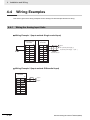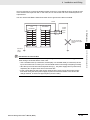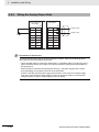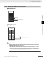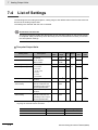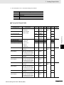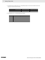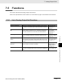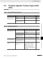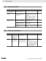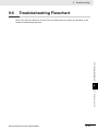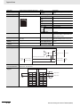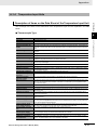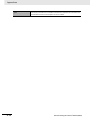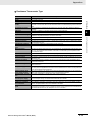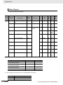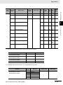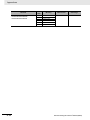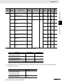
1
Machine Automation Controller
NX-series
Analog I/O Units
User’s Manual
NX-AD@@@@
NX-DA@@@@
NX-TS@@@@
Analog I/O Units
W522-E1-01
© OMRON, 2013
All rights reserved. No part of this publication may be reproduced, stored in a retrieval system, or transmitted, in any form, or
by any means, mechanical, electronic, photocopying, recording, or otherwise, without the prior written permission of
OMRON.
No patent liability is assumed with respect to the use of the information contained herein. Moreover, because OMRON is
constantly striving to improve its high-quality products, the information contained in this manual is subject to change without
notice. Every precaution has been taken in the preparation of this manual. Nevertheless, OMRON assumes no responsibility
for errors or omissions. Neither is any liability assumed for damages resulting from the use of the information contained in
this publication.
Trademarks
• Sysmac and SYSMAC are trademarks or registered trademarks of OMRON Corporation in Japan and other
countries for OMRON factory automation products.
• Windows, Windows 98, Windows XP, Windows Vista, and Windows 7 are registered trademarks of Microsoft
Corporation in the USA and other countries.
• EtherCAT® is registered trademark and patented technology, licensed by Beckhoff Automation GmbH, Germany.
• ODVA, CIP, CompoNet, DeviceNet, and EtherNet/IP are trademarks of ODVA.
• The SD logo is a trademark of SD-3C, LLC.
Other company names and product names in this document are the trademarks or registered trademarks of their
respective companies.
Introduction
Introduction
Thank you for purchasing a NX-series Analog I/O Unit.
This manual contains information that is necessary to use the NX-series Analog I/O Unit. Please read
this manual and make sure you understand the functionality and performance of the NX-series Analog
I/O Unit before you attempt to use it in a control system.
Keep this manual in a safe place where it will be available for reference during operation.
Intended Audience
This manual is intended for the following personnel, who must also have knowledge of electrical systems (an electrical engineer or the equivalent).
• Personnel in charge of introducing FA systems.
• Personnel in charge of designing FA systems.
• Personnel in charge of installing and maintaining FA systems.
• Personnel in charge of managing FA systems and facilities.
For programming, this manual is intended for personnel who understand the programming language
specifications in international standard IEC 61131-3 or Japanese standard JIS B3503.
Applicable Products
This manual covers the following product.
• NX-series Analog I/O Unit
NX-AD
/DA
/TS
NX-series Analog I/O Unit User’s Manual (W522)
1
CONTENTS
CONTENTS
Introduction .............................................................................................................. 1
Relevant Manuals ..................................................................................................... 6
Manual Structure ...................................................................................................... 8
Read and Understand this Manual........................................................................ 10
Safety Precautions ................................................................................................. 13
Precautions for Safe Use ....................................................................................... 17
Precautions for Correct Use.................................................................................. 21
Regulations and Standards ................................................................................... 22
Unit Versions .......................................................................................................... 24
Related Manuals ..................................................................................................... 27
Terminology ............................................................................................................ 30
Revision History ..................................................................................................... 32
Sections in this Manual ......................................................................................... 33
Section 1
1-1
Features and System Configuration
Features and Types of Analog I/O Units.............................................................................. 1-2
1-1-1
1-1-2
1-2
System Configuration of Slave Terminals........................................................................... 1-3
1-2-1
1-2-2
1-3
2
Analog Input Units..................................................................................................................... 1-11
Analog Output Units .................................................................................................................. 1-12
Temperature Input Units............................................................................................................ 1-13
Support Software................................................................................................................. 1-14
1-5-1
Section 2
Model Notation ............................................................................................................................ 1-5
Analog Input Units....................................................................................................................... 1-7
Analog Output Units .................................................................................................................... 1-9
Temperature Input Units............................................................................................................ 1-10
List of Functions.................................................................................................................. 1-11
1-4-1
1-4-2
1-4-3
1-5
Overview ..................................................................................................................................... 1-3
System Configuration.................................................................................................................. 1-3
Model List............................................................................................................................... 1-5
1-3-1
1-3-2
1-3-3
1-3-4
1-4
Analog I/O Unit Features............................................................................................................. 1-2
Analog I/O Unit Types ................................................................................................................. 1-2
Applicable Support Software..................................................................................................... 1-14
Specifications
2-1
General Specifications .......................................................................................................... 2-2
2-2
Individual Specifications....................................................................................................... 2-3
NX-series Analog I/O Unit User’s Manual (W522)
CONTENTS
Section 3
3-1
Part Names and Functions
Part Names............................................................................................................................. 3-2
3-1-1
3-2
Indicators ............................................................................................................................... 3-8
3-2-1
Section 4
4-1
Installing NX Units ................................................................................................................. 4-2
Section 5
Wiring the Analog Input Units.................................................................................................... 4-34
Wiring the Analog Output Units................................................................................................. 4-36
Wiring the Temperature Input Units........................................................................................... 4-37
Precautions when Using Common Power Supply for Input Devices of Analog Input Units ...... 4-38
I/O Refreshing
I/O Refreshing for Slave Terminals ...................................................................................... 5-2
5-1-1
5-2
Wiring to the Screwless Clamping Terminal Block .................................................................... 4-15
Checking the Wiring .................................................................................................................. 4-33
Wiring Examples.................................................................................................................. 4-34
4-4-1
4-4-2
4-4-3
4-4-4
5-1
Power Supply Types ................................................................................................................... 4-8
Supplying Each Power Supply and Wiring.................................................................................. 4-9
Calculating the Total Current Consumption from I/O Power Supply ......................................... 4-11
Power Supply-related Units for the NX-series........................................................................... 4-12
Wiring the Terminals ........................................................................................................... 4-15
4-3-1
4-3-2
4-4
Installing NX Units....................................................................................................................... 4-2
Attaching Markers ....................................................................................................................... 4-4
Removing NX Units..................................................................................................................... 4-5
Installation Orientation ................................................................................................................ 4-7
Wiring the Power Supply to the Slave Terminal ................................................................. 4-8
4-2-1
4-2-2
4-2-3
4-2-4
4-3
TS Indicator................................................................................................................................. 3-9
Installation and Wiring
4-1-1
4-1-2
4-1-3
4-1-4
4-2
Screwless Clamping Terminal Block Type .................................................................................. 3-2
I/O Refreshing from CPU Unit to Slave Terminal ........................................................................ 5-2
I/O Refreshing Methods ........................................................................................................ 5-3
5-2-1
5-2-2
5-2-3
5-2-4
5-2-5
5-2-6
Section 6
Types of I/O Refreshing Methods................................................................................................ 5-3
Setting the I/O Refreshing Methods ............................................................................................ 5-3
Selecting NX Units ...................................................................................................................... 5-4
Free-Run Refreshing................................................................................................................... 5-4
Synchronous Input Refreshing.................................................................................................... 5-9
Synchronous Output Refreshing ............................................................................................... 5-13
Analog Input Units
6-1
Types of Analog Input Units ................................................................................................. 6-2
6-2
Input Range and Converted Values ..................................................................................... 6-4
6-3
Specifications of I/O Data ..................................................................................................... 6-6
6-3-1
6-4
6-5
Allocable I/O Data ....................................................................................................................... 6-6
List of Settings....................................................................................................................... 6-8
Function ............................................................................................................................... 6-12
6-5-1
6-5-2
6-5-3
6-5-4
6-5-5
6-5-6
List of Analog Input Unit Functions ........................................................................................... 6-12
Selecting Channel To Use......................................................................................................... 6-13
Moving Average ........................................................................................................................ 6-19
Input Disconnection Detection .................................................................................................. 6-27
Over Range/Under Range Detection ........................................................................................ 6-28
User Calibration ........................................................................................................................ 6-29
NX-series Analog I/O Unit User’s Manual (W522)
3
CONTENTS
Section 7
Analog Output Units
7-1
Types of Analog Output Units .............................................................................................. 7-2
7-2
Output Range and Output Set Values.................................................................................. 7-3
7-3
Specifications of I/O Data ..................................................................................................... 7-5
7-3-1
7-4
7-5
Allocable I/O Data ....................................................................................................................... 7-5
List of Settings....................................................................................................................... 7-6
Functions ............................................................................................................................... 7-9
7-5-1
7-5-2
7-5-3
7-5-4
7-5-5
Section 8
List of Analog Output Unit Functions........................................................................................... 7-9
Selecting Channel To Use......................................................................................................... 7-10
Load Rejection Output Setting .................................................................................................. 7-15
Over Range/Under Range Detection ........................................................................................ 7-21
User Calibration ........................................................................................................................ 7-22
Temperature Input Units
8-1
Types of Temperature Input Units ........................................................................................ 8-2
8-2
Input Types and Input Ranges.............................................................................................. 8-3
8-2-1
8-2-2
8-3
Corresponding Input Types and Input Ranges............................................................................ 8-3
Setting Methods .......................................................................................................................... 8-5
Specifications of I/O Data ..................................................................................................... 8-9
8-3-1
8-4
8-5
Allocable I/O Data ....................................................................................................................... 8-9
List of Settings..................................................................................................................... 8-14
Functions ............................................................................................................................. 8-19
8-5-1
8-5-2
8-5-3
8-5-4
8-5-5
8-5-6
8-5-7
8-5-8
8-5-9
8-5-10
8-6
Measured Values Used When an Error Occurs ................................................................ 8-56
Section 9
Troubleshooting
9-1
How to Check for Errors ....................................................................................................... 9-2
9-2
Checking for Errors with the Indicators .............................................................................. 9-3
9-3
Checking for Errors and Troubleshooting on the Sysmac Studio.................................... 9-6
9-3-1
9-3-2
9-3-3
9-3-4
9-3-5
9-4
9-5
9-6
Checking for Errors from the Sysmac Studio .............................................................................. 9-6
Event Codes and Corrections for Errors ..................................................................................... 9-9
Meaning of Error ....................................................................................................................... 9-16
Error Descriptions of Analog Input Units and Analog Output Units........................................... 9-17
Error Descriptions of Temperature Input Units .......................................................................... 9-35
Resetting Errors .................................................................................................................. 9-44
Troubles Specific To Each Type of NX Units..................................................................... 9-45
9-5-1
9-5-2
9-5-3
9-5-4
4
List of Temperature Input Unit Functions ..................................................................................8-19
Function Block Diagram ............................................................................................................ 8-20
Selecting Channel To Use......................................................................................................... 8-21
Moving Average ........................................................................................................................ 8-26
Sensor Disconnection Detection ............................................................................................... 8-31
Over Range/Under Range Detection ........................................................................................ 8-32
Cold Junction Compensation Enable/Disable Setting............................................................... 8-33
Temperature Unit (°C/°F) Setting .............................................................................................. 8-38
Input Correction......................................................................................................................... 8-43
Decimal Point Position Setting .................................................................................................. 8-50
Analog I/O Units (Common) ...................................................................................................... 9-45
Analog Input Units..................................................................................................................... 9-45
Analog Output Units .................................................................................................................. 9-46
Temperature Input Units............................................................................................................ 9-46
Troubleshooting Flowchart ................................................................................................ 9-47
NX-series Analog I/O Unit User’s Manual (W522)
CONTENTS
Section 10
Inspection and Maintenance
10-1 Cleaning and Inspection ..................................................................................................... 10-2
10-1-1 Cleaning.................................................................................................................................... 10-2
10-1-2 Periodic Inspection ................................................................................................................... 10-2
10-2 Maintenance Procedures .................................................................................................... 10-5
10-2-1 Backing Up Data....................................................................................................................... 10-5
10-2-2 Replacement Procedure for NX Units....................................................................................... 10-6
Appendices
A-1 Data Sheet ..............................................................................................................................A-2
A-1-1
A-1-2
A-1-3
A-1-4
Model List ................................................................................................................................... A-2
Analog Input Units ...................................................................................................................... A-5
Analog Output Units.................................................................................................................. A-24
Temperature Input Units ........................................................................................................... A-37
A-2 Dimensions ..........................................................................................................................A-47
A-2-1
Screwless Clamping Terminal Block Type ................................................................................ A-47
A-3 List of NX Objects................................................................................................................A-49
A-3-1
A-3-2
A-3-3
A-3-4
Format of Object Descriptions .................................................................................................. A-49
Analog Input Units .................................................................................................................... A-50
Analog Output Units.................................................................................................................. A-59
Temperature Input Units ........................................................................................................... A-64
Index
NX-series Analog I/O Unit User’s Manual (W522)
5
Relevant Manuals
Relevant Manuals
To use the Analog I/O Unit, you must refer to the manuals for all related products.
Read all of the manuals that are relevant to your system configuration and application before you use
the NX-series Analog I/O Unit.
Most operations are performed from the Sysmac Studio Automation Software. Refer to the Sysmac Studio Version 1 Operation Manual (Cat. No. W504) for information on the Sysmac Studio.
NX Series
NX-series Data Reference
Manual
All Units
NX-series Position Interface Units
User's Manual
NX-series System Units User's
Manual
NX-series Analog I/O Units User's
Manual
NX Units
NX-series Digital I/O Units User′s
Manual
NJ-series Troubleshooting
Manual
NJ-series CPU Unit Built-in
EtherCAT Port User's Manual
NJ-series CPU Unit Motion
Control User's Manual
NJ-series CPU Unit Software
User's Manual
NJ-series CPU Unit Hardware
User's Manual
NJ Series
NX-series EtherCAT Coupler Unit
User's Manual
Communications
Coupler
Unit
Learning about the
NX-series Units
Specifications
z
z
z
z
z
Functionality
z
z
z
z
z
Application procedures
z
z
z
z
z
Learning about Slave Terminals
z
Slave Terminal specifications
z
System configuration
z
Rules on building
systems
z
Slave Terminal application procedures
z
Slave Terminal installation procedures
z
Support Software
connection procedures
z
Procedure to estimate Slave Terminal
performance
z
Using NX-series Units with
NJ-series Controllers
Using a Slave Terminal connected to the
built-in EtherCAT port
on an NJ-series CPU
Unit
Procedures for performing motion control with Position
Interface Units
6
z
z
z
z
z
z
NX-series Analog I/O Unit User’s Manual (W522)
Managing errors for
the overall NJ-series
Controller
Troubleshooting
Slave Terminals and
Communications
Coupler Units
Performing Unit maintenance
Referencing data lists for
NX Unit power consumptions, weights, etc.
NX-series Analog I/O Unit User’s Manual (W522)
Troubleshooting NX
Units
z
NX Units
z
z
z
z
z
z
z
z
NX-series Data Reference
Manual
NX-series Position Interface Units
User's Manual
NX-series System Units User's
Manual
Communications
Coupler
Unit
NX-series Analog I/O Units User's
Manual
NX-series Digital I/O Units User′s
Manual
NJ Series
NX-series EtherCAT Coupler Unit
User's Manual
NJ-series Troubleshooting
Manual
NJ-series CPU Unit Built-in
EtherCAT Port User's Manual
NJ-series CPU Unit Motion
Control User's Manual
NJ-series CPU Unit Software
User's Manual
NJ-series CPU Unit Hardware
User's Manual
Relevant Manuals
NX Series
All Units
Troubleshooting
z
z
z
7
Manual Structure
Manual Structure
Page Structure and Icons
The following page structure and icons are used in this manual.
Mounting Units
Level 1 heading
Level 2 heading
Level 3 heading
Connecting Controller Components
Gives the current
headings.
4 Installation and Wiring
Level 2 heading
Level 3 heading
4-3
4-3-1
The Units that make up an NJ-series Controller can be connected simply by pressing the Units together
and locking the sliders by moving them toward the back of the Units. The End Cover is connected in the
same way to the Unit on the far right side of the Controller.
A step in a procedure
1
Join the Units so that the connectors fit exactly.
Hook
Indicates a procedure.
Hook holes
Connector
4-3 Mounting Units
4
4 -3 -1 C onne c ting C ontrolle r C ompone nts
2
The yellow sliders at the top and bottom of each Unit lock the Units together. Move the sliders
toward the back of the Units as shown below until they click into place.
Move the sliders toward the back
until they lock into place.
Lock
Release
Slider
Special information
Icons indicate precautions,
additional information, or
reference information.
Manual name
Page tab
Gives the number of
the main section.
Precautions for Correct Use
The sliders on the tops and bottoms of the Power Supply Unit, CPU Unit, I/O Units, Special I/O Units,
and CPU Bus Units must be completely locked (until they click into place) after connecting the
adjacent Unit connectors.
NJ-series CPU Unit Hardware User’s Manual (W500)
4-9
Note This illustration is provided only as a sample. It may not literally appear in this manual.
8
NX-series Analog I/O Unit User’s Manual (W522)
Manual Structure
Special Information
Special information in this manual is classified as follows:
Precautions for Safe Use
Precautions on what to do and what not to do to ensure safe usage of the product.
Precautions for Correct Use
Precautions on what to do and what not to do to ensure proper operation and performance.
Additional Information
Additional information to read as required.
This information is provided to increase understanding or make operation easier.
Version Information
Information on differences in specifications and functionality for CPU Units and EtherCAT Coupler Units with different unit versions and for different versions of the Sysmac Studio is given.
Note References are provided to more detailed or related information.
Precaution on Terminology
• In this manual, “download” refers to transferring data from the Sysmac Studio to the physical Controller and “upload” refers to transferring data from the physical Controller to the Sysmac Studio.
For the Sysmac Studio, synchronization is used to both upload and download data. Here, “synchronize” means to automatically compare the data for the Sysmac Studio on the computer with the data
in the physical Controller and transfer the data in the direction that is specified by the user.
• In this manual, the directions in relation to the Units are given in the following figure, which shows
upright installation.
Up
Left
Right
Down
NX-series Analog I/O Unit User’s Manual (W522)
9
Read and Understand this Manual
Read and Understand this Manual
Please read and understand this manual before using the products. Please consult your OMRON
representative if you have any questions or comments.
Warranty and Limitations of Liability
WARRANTY
OMRON's exclusive warranty is that the products are free from defects in materials and workmanship for a
period of one year (or other period if specified) from date of sale by OMRON.
OMRON MAKES NO WARRANTY OR REPRESENTATION, EXPRESS OR IMPLIED, REGARDING
NON-INFRINGEMENT, MERCHANTABILITY, OR FITNESS FOR PARTICULAR PURPOSE OF THE
PRODUCTS. ANY BUYER OR USER ACKNOWLEDGES THAT THE BUYER OR USER ALONE HAS
DETERMINED THAT THE PRODUCTS WILL SUITABLY MEET THE REQUIREMENTS OF THEIR
INTENDED USE. OMRON DISCLAIMS ALL OTHER WARRANTIES, EXPRESS OR IMPLIED.
LIMITATIONS OF LIABILITY
OMRON SHALL NOT BE RESPONSIBLE FOR SPECIAL, INDIRECT, OR CONSEQUENTIAL DAMAGES,
LOSS OF PROFITS OR COMMERCIAL LOSS IN ANY WAY CONNECTED WITH THE PRODUCTS,
WHETHER SUCH CLAIM IS BASED ON CONTRACT, WARRANTY, NEGLIGENCE, OR STRICT
LIABILITY.
In no event shall the responsibility of OMRON for any act exceed the individual price of the product on which
liability is asserted.
IN NO EVENT SHALL OMRON BE RESPONSIBLE FOR WARRANTY, REPAIR, OR OTHER CLAIMS
REGARDING THE PRODUCTS UNLESS OMRON'S ANALYSIS CONFIRMS THAT THE PRODUCTS
WERE PROPERLY HANDLED, STORED, INSTALLED, AND MAINTAINED AND NOT SUBJECT TO
CONTAMINATION, ABUSE, MISUSE, OR INAPPROPRIATE MODIFICATION OR REPAIR.
10
NX-series Analog I/O Unit User’s Manual (W522)
Read and Understand this Manual
Application Considerations
SUITABILITY FOR USE
OMRON shall not be responsible for conformity with any standards, codes, or regulations that apply to the
combination of products in the customer's application or use of the products.
At the customer's request, OMRON will provide applicable third party certification documents identifying
ratings and limitations of use that apply to the products. This information by itself is not sufficient for a
complete determination of the suitability of the products in combination with the end product, machine,
system, or other application or use.
The following are some examples of applications for which particular attention must be given. This is not
intended to be an exhaustive list of all possible uses of the products, nor is it intended to imply that the uses
listed may be suitable for the products:
• Outdoor use, uses involving potential chemical contamination or electrical interference, or conditions or
uses not described in this manual.
• Nuclear energy control systems, combustion systems, railroad systems, aviation systems, medical
equipment, amusement machines, vehicles, safety equipment, and installations subject to separate
industry or government regulations.
• Systems, machines, and equipment that could present a risk to life or property.
Please know and observe all prohibitions of use applicable to the products.
NEVER USE THE PRODUCTS FOR AN APPLICATION INVOLVING SERIOUS RISK TO LIFE OR
PROPERTY WITHOUT ENSURING THAT THE SYSTEM AS A WHOLE HAS BEEN DESIGNED TO
ADDRESS THE RISKS, AND THAT THE OMRON PRODUCTS ARE PROPERLY RATED AND
INSTALLED FOR THE INTENDED USE WITHIN THE OVERALL EQUIPMENT OR SYSTEM.
PROGRAMMABLE PRODUCTS
OMRON shall not be responsible for the user's programming of a programmable product, or any
consequence thereof.
NX-series Analog I/O Unit User’s Manual (W522)
11
Read and Understand this Manual
Disclaimers
CHANGE IN SPECIFICATIONS
Product specifications and accessories may be changed at any time based on improvements and other
reasons.
It is our practice to change model numbers when published ratings or features are changed, or when
significant construction changes are made. However, some specifications of the products may be changed
without any notice. When in doubt, special model numbers may be assigned to fix or establish key
specifications for your application on your request. Please consult with your OMRON representative at any
time to confirm actual specifications of purchased products.
DIMENSIONS AND WEIGHTS
Dimensions and weights are nominal and are not to be used for manufacturing purposes, even when
tolerances are shown.
PERFORMANCE DATA
Performance data given in this manual is provided as a guide for the user in determining suitability and does
not constitute a warranty. It may represent the result of OMRON's test conditions, and the users must
correlate it to actual application requirements. Actual performance is subject to the OMRON Warrant