1
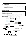
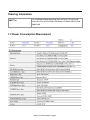
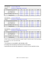
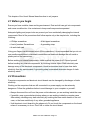
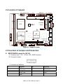
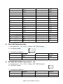
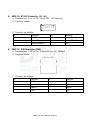
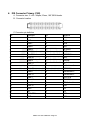
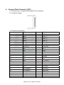
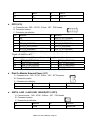
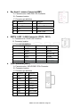
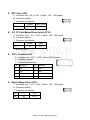
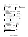
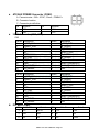
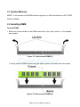
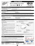
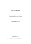
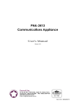
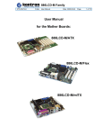
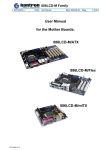
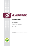
96M5771o Single Board Computer User’s Manual Edition 1.0 2007 k Preface Copyright This publication, including all photographs, illustrations and software, is protected under international copyright laws, with all rights reserved. No part of this manual maybe reproduced, copied, translated or transmitted in any form or by any means without the prior written consent from DSM Computer AG. Version 1.0 Copyright 2007 Disclaimer The information in this document is subject to change without prior notice and does not represent commitment from DSM Computer AG. However, users may update their knowledge of any product in use by constantly checking its manual posted on our website: http://www.DSM.AG. The DSM shall not be liable for direct, indirect, special, incidental, or consequential damages arising out of the use of any product, nor for any infringements upon the rights of third parties, which may result from such use. Any implied warranties of merchantability of fitness for any particular purpose is also disclaimed. Acknowledgements The 96M5771o is a trademark of DSM Computer AG. All other product names mentioned herein are registered trademarks of their respective owners. Regulatory Compliance Statements This section provides the FCC compliance statement for Class A devices and describes how to keep the system CE compliant. Federal Communications Commission (FCC) For Class A Device This equipment has been tested and verified to comply with the limits for a Class A digital device, pursuant to Part 15 of FCC Rules. These limits are designed to provide reasonable protection against harmful interference when the equipment is operated in a commercial environment. This equipment generates, uses, and can radiate radio frequency energy and, if not installed and used in accordance with the instructions, may cause harmful interference to radio communications. Operation of this equipment in a residential area (domestic environment) is likely to cause harmful interference, in which case the user will be required to correct the interference (take adequate measures) at their own expense. 96M5771o User's Manual / Page 2 CE Certification The product(s) described in this manual complies with all applicable European Union (CE) directives if it has a CE marking. For computer systems to remain CE compliant, only CE-compliant parts may be used. Maintaining CE compliance also requires proper cable and cabling techniques. WARNINGS Read and adhere to all warnings, cautions, and notices in this guide and the documentation supplied with the chassis, power supply, and accessory modules. If the instructions for the chassis and power supply are inconsistent with these instructions or the instructions for accessory modules, contact the supplier to find out how you can ensure that your computer meets safety and regulatory requirements. CAUTION Electrostatic discharge (ESD) can damage NSA components. Do the described procedures only at an ESD workstation. If no such station is available, you can provide some ESD protection by wearing an antistatic wrist strap and attaching it to a metal part of the computer chassis. Safety Information Before installing and using the 96m5771o, note the following precautions: Read all instructions carefully. Do not place the unit on an unstable surface, cart, or stand. Follow all warnings and cautions in this manual. When replacing parts, ensure that your service technician uses parts specified by the manufacturer. Avoid using the system near water, in direct sunlight, or near a hearing device. 96M5771o User's Manual / Page 3 Table of Content Preface 2 Copyright 2 Disclaimer Acknowledgements Regulatory Compliance Statements Federal Communications Commission (FCC) For Class A Device CE Certification Safety Information Table of Content 2 2 2 3 3 3 3 Chapter 1 General Information 1.1 Main Feature 6 1.2 Specifications 1.3 Power Consumption Measurement 1.4 Board Layout 1.5 Board Dimensions 7 9 11 11 Chapter 2 Jumper Setting 2.1 Before you begin 2.2 Precautions 2.3 Setting Jumpers 2.4 Location of Jumpers 2.5 Function of Jumper 13 13 14 15 15 Chapter 3 Expansion 3.1 System Memory 3.2 Installing DIMM 3.3 Installing Compact Flash 30 30 32 96M5771o User's Manual / Page 4 Chapter 1 General Information 96M5771o User's Manual / Page 5 1.1 Product Feature Intel Core Solo & Core Duo and Core 2 Duo Processor Family support Intel 945GM Chipsets Two 240-pin DDR2 DIMM Socket support un-buffered non-ECC DDR2 400/533/667 up to 4GB Intel 82573L PCI Express Gigabit LAN X 2 Support LVDS /VGA Display and one x16 PCI Express slot CompactFlash Socket Product Overview: The 96M5771o is a 5.25” embedded board featuring Intel Core Solo, Core Duo and Core 2 Duo processor with 533/667 MHz FSB; speed up to 2.33 (2.0) GHz. The 96M5771o offers high performance and various processors and PCI Express; versatile display and I/O port selections, which is the best solution for advanced embedded applications. Block Diagram: Intel® Core 2 Duo, Core Duo,Core Solo 533 / 667 MHz FSB DDR2 Channel A LVDS Intel® 945GM VGA DDR2 DIMM Modules DDR2 533 / 667 MHz DDR2 Channel B DDR2 Slot DDR2 Slot PCIex16 Slot 4 Lanes Front Panel Internal Conn . 0/1 2,3/4/5 CF & IDE 2GB/s USB2.0 Intel® ICH7-M DH UltraDMA 33/66/100 PCIex1 Port (1) PCI 32 Bit / 33 MHz Bus SATA 1 SATA 2 SATA INTEL 82573 L GbE RJ45 (LAN 1) INTEL 82573 L GbE RJ45 (LAN 2) PCI-Slot ALC655 LPC BUS KB /MS IrDA SIO1 SIO2 IT8712 F IT 8712F COM1,2 LPT GPIO COM3,4 96M5771o User's Manual / Page 6 1.2 Specification: General CPU Front Side Bus Chipset Memory Super I/O BIOS Expansion interface Dimensions (Lx W) mm/inch System Management Watchdog Timer Monitoring Intel® Core Solo and Core Duo family processors Core 2 Duo family CPU (optional) 533/667 MHz Intel 945GM and ICH7-M DH 2 x 240-pin DDR2 DIMM socket, up to 4GB un-buffered non-ECC DDR2 533/667 SDRAM ITE 8712F Award system BIOS Plug & Play support Advanced Power Management and Advanced Configuration & Power Interface support 4M bits flash ROM 1 x PCI Slot 1 x PCI Express x 16 Slot 203mm(L) x 143mm(W) 1 minute increments from 1 to 255 minutes 1 second increments from 1 to 255 seconds Tolerance 15% under room temperature 25°C Derived from Super IO to support system monitor. Monitoring of 5 voltages, 3 temperature and 3 fans Speed. 5 voltage (For +3.3V, +5V, +12V, Vcore and +2.5V) 3 Temperatures (CPU, two external Temperature Sensor) 3 FANs speed (CPU and System FANs) Display Chipset Display Memory Display interface and Resolution Intel® 945GM integrated graphics solution w/ Intel® Extreme Graphics 2 technology Up to 64 MB of dynamic video memory allocation CRT- Analog Display Support Drive a standard progressive scan analog monitor with pixel resolution up to 1400 x 1050 LVDS - LFP (local flat panel) LVDS interface Single- or dual-pixel LVDS panel support CCFL x1 for LCD Panel Backlight Inverter Power Pin 2,3 support 12VDC power source for inverter: Max. 12VDC@2A for each Ethernet Controller Intel® 82573L PCI Express Gigabit Ethernet Controller x 2 supporting two GbE LAN ports Support Boot From LAN (PXE) Support Wake on LAN (When 5Vsb power available). (LAN1 only) Interface 2 x RJ45 with LED connector LED Active, Link 100, and 1000 LAN LED LAN Status LED defined: 10: LED Off / 100: Green LED / 1000: Orange LED Extra (External) LED: 2 x 4 pin header 96M5771o User's Manual / Page 7 Audio AC97 Audio CODEC Realtek RTL655 CODEC for AC97 v2.1 CODEC Line in with pin header Microphone in and Speaker out Interface I/O Interface USB 2.0 Serial ports Parallel ports PS/2 GPIO FAN IrDA Others 6 x USB 2.0 port (2 on front, 4 on Board by one 2.0 mm JST Connectors), bandwidth: 480 Mb/s SIO× 4, support RS-232 with pin headers 1 x3-pin jumper to switch 5V and 12V power source 1 x Box header 26-pin connector 1 x PS/2 connector for Keyboard and Mouse 8 GPIO lines via header (GPI 0~3 and GPO 0~3); GPO0 and GPO1 could be connected to LED for programmable feature TTL Level (0/5V) 1x 4-pin FAN JST connector (for CPU) 2x 3-pin FAN connector x 2 (for System) On board pin header for IrDA Tx Rx On Board buzzer Power LED/HDD Power LED SMBus 2.0 controller (2 pin header) On board 2 pin header for reset (for power on button switch) On-board RTC On-chip RTC with battery back up External Lithium battery x 1 RTC Tolerance less than 2sec (24 hours) under 25˚C environment Storage Support CF SATA IDE Disk on Module Power Supply Type ATX mode AT mode Power consumption Environment Operating Temperature Storage Temperature Relative Humidity 1x Internal CompactFlash socket Support One Type I& II Compact Flash Card (Primary Master) 2 x SATA ports, support Raid 0,1, bandwidth: 150 MB/s 1 x 44-pin IDE connector 1 x 2-pin Jst power (+5V,GND ) for DOM Support both AT and ATX Mode Factory default setting is AT mode +5V / -5V / 5Vsb Power In (+12V/-12V for PC 104 plus) When Change to ATX Mode, the BIOS default setting is as follow: POWER -SUPPLY TYPE [ATX] AUTO PWR-FAILURE RESUME [ON] +5V Power in No Power On push Button, Software Shutdown function and LAN remote wake up 43.2 W in 12V, 121.2 W in 5V, and 11.5W in 5Vsb 0°C ~ 60°C -20˚C to 85˚C Operating 10%~90%, non-condensing Non-operating 5%~95%, non-condensing Certifications CE approval FCC Class A 96M5771o User's Manual / Page 8 Ordering Information: 96M5771o 5.25” Embedded Board supporting Intel Core Solo, Core Duo and Core 2 Duo CPU w/VGA/ Dual LVDS/Audio/4 COMs/6 USB2.0 /Dual Gigabit LAN 1.3 Power Consumption Measurement 96M5771o User's Manual / Page 9 The Data is based on fully possible configurations installed on 96M5771o include the Add-on Card, and peripherals such as USB devices, SCSI Card and SCSI HDD. Test Criteria: 1. Test configuration is include 96M5771o, HDD, CD-ROM, and FDD. 2. Full loading mode should utilize CPU 100% with run Burn-in test program. 3. Light loading mode will utilize CPU loading below 5%, and there is no data or application running. 96M5771o User's Manual / Page 10 1.4 Board Layout Figure 1.2: Overview 1.5 Board Dimensions Figure 1.3: Mechanical Drawing 96M5771o User's Manual / Page 11 Chapter 2 Jumper Setting 96M5771o User's Manual / Page 12 This chapter of the User’s Manual describes how to set jumpers. 2.1 Before you begin Ensure you have a stable, clean working environment. Dust and dirt can get into components and cause a malfunction. Use containers to keep small components separated. Adequate lighting and proper tools can prevent you from accidentally damaging the internal components. Most of the procedures that follow require only a few simple tools, including the following: • A Philips screwdriver • A set of jewelers Screwdrivers • An anti-static pad • A flat-tipped screwdriver • A grounding strap Using your fingers can disconnect most of the connections. It is recommended that you do not use needle-nosed pliers to disconnect connections as these can damage the soft metal or plastic parts of the connectors. Before working on internal components, make sure that the power is off. Ground yourself before touching any internal components, by touching a metal object. Static electricity can damage many of the electronic components. Humid environment tend to have less static electricity than dry environments. A grounding strap is warranted whenever danger of static electricity exists. 2.2 Precautions Computer components and electronic circuit boards can be damaged by discharges of static electricity. Working on the computers that are still connected to a power supply can be extremely dangerous. Follow the guidelines below to avoid damage to your computer or yourself: • Always disconnect the unit from the power outlet whenever you are working inside the case. • If possible, wear a grounded wrist strap when you are working inside the computer case. Alternatively, discharge any static electricity by touching the bare metal chassis of the unit case, or the bare metal body of any other grounded appliance. • Hold electronic circuit boards by the edges only. Do not touch the components on the board unless it is necessary to do so. Don’t flex or stress the circuit board. 96M5771o User's Manual / Page 13 • Leave all components inside the static-proof packaging that they shipped with until they are ready for installation. • Use correct screws and do not over tighten screws. 2.3 Setting Jumpers A jumper is the simplest kind of electric switch. It consists of two metal pins and a cap. When setting the jumpers, ensure that the jumper caps are placed on the correct pins. When the jumper cap is placed on both pins, the jumper is SHORT. If you remove the jumper cap, or place the jumper cap on just one pin, the jumper is OPEN. Please see the following illustrations The illustrations on the right show a 2-pin jumper. When the jumper cap is placed on both pins, the jumper is SHORT. If you remove the jumper cap, or place the jumper cap on just one pin, the jumper is OPEN. Open (Off) These illustrations show a 3-pin jumper. Pins 1 and 2 are SHORT. Table 2-1: Setting Jumpers 96M5771o User's Manual / Page 14 Short (On) 2.4 Location of Jumpers CON 1 (ATX Power CON.) 1 CN4 JP3 1 COM x 4 JP4 1 1 J5 JP7 JP13 JP14 JP20 1 1 1 1 1 1 1 1 MIC IN JP5 JP8 Speaker Out PCI 1 DIMM x2 CPU J11 Compact Flash =PIN 1 V G JP15 A IDE JP16 1 1 1 J7 JP17 LAN1 J3 SB L P T NB LAN2 (INTEL,ICH7) (INTEL,945GM) 1 JP6 JP12 1 JP9 PCI-e x 16 Slot LVDS J1 JP19 LVDS JP1 1 1 CCFL J2 USB J6 1 USB J4 1 JP11 USBx 2 CON 2 (ATX AUX Power CON.) 1 SATA SATA 1 KB/ MS J10 1 1 11 JP18 JP21 Figure 2-1: Jumper Location 2.5 Functions of Jumpers and Connectors SATA1/SATA0 connector (J8, J9) A . Connector size : 7 Pin , 1.27mm ,180°, SATA Connector B . Connector location C. Connector pin definition Pin Definition Pin Definition 1 GND 5 SATA_RXN 2 SATA_TXP 6 SATA_RXP 3 SATA_TXN 7 GND 4 GND 96M5771o User's Manual / Page 15 PIO Connector (CN1) A . Connector size : 2 X 13 = 26 Pin ,2.0 mm, 180° ,BOX Header B . Connector location C . Connector pin definition Pin Definition Pin Definition 1 Line Print Strobe 14 Auto Feed# 2 Parallel Data 0 15 Error# 3 Parallel Data 1 16 Initialize# 4 Parallel Data 2 17 Select Input# 5 Parallel Data 3 18 GND 6 Parallel Data 4 19 GND 7 Parallel Data 5 20 GND 8 Parallel Data 6 21 GND 9 Parallel Data 7 22 GND 10 Acknowledge# 23 GND 11 Busy 24 GND 12 Paper empty 25 GND 13 Select 26 NC SIO Connector (CN6) A . Connector size: 2 X 20 = 40 Pin ,2.0 mm, 180° ,BOX Header B . Connector location C . Connector pin definition Pin Definition Pin Definition 1 DCD1 21 DCD3 2 DSR1 22 DSR3 3 RXD1 23 RXD3 96M5771o User's Manual / Page 16 4 RTS1 24 RTS3 5 TXD1 25 TXD3 6 CTS1 26 CTS3 7 DTR1 27 DTR3 8 RI1 28 RI3 9 GND 29 GND 10 NC 30 NC 11 DCD2 31 DCD4 12 DSR2 32 DSR4 13 RXD2 33 RXD4 14 RTS2 34 RTS4 15 TXD2 35 TXD4 16 CTS2 36 CTS4 17 DTR2 37 DTR4 18 RI2 38 RI4 19 GND 39 GND 20 NC 40 NC CPU FAN Connector(CN4) A . Connector size : 1 X 4 = 4 Pin , 2.54mm ,180°, FAN Connector B . Connector location C . Connector pin definition Pin Definition Pin Definition 1 GND 3 Sense 2 +12V 4 NC SYSTEM FAN1/FAN2 Connector(J1 , J5) A . Connector size : 1 X 3 = 3 Pin , 2.54mm ,180°, FAN Connector B . Connector location C . Connector pin definition Pin Definition Pin Definition 1 GND 3 Sense 2 +12V 96M5771o User's Manual / Page 17 USB 2.0 , 0/1/4/5 Connector (J4 , J6 ) A . Connector size : 1 X 6 = 6 Pin , 2.0mm ,180°, JST Connector B . Connector location C . Connector pin definition Pin Definition Pin Definition 1 +5VSB 4 Data 1-/Data 5- 2 Data 0-/Data 4- 5 Data 1+/Data 5+ 3 Data 0+/Data 4+ 6 GND USB 2.0 , 2/3 Connector (CN9) A . Connector size : 1 X 6 = 6 Pin , 15.2x16.8x17mm, 90°, FEMALE B . Connector location C . Connector pin definition Pin Definition Pin Definition 1 +5VSB 5 +5VSB 2 Data 2- 6 Data 3- 3 Data 2+ 7 Data 3+ 4 GND 8 GND 96M5771o User's Manual / Page 18 IDE Connector Primary (CN8) A . Connector size : 2 x 22 = 44pins,2.0mm, 180°,BOX Header B . Connector location C. Connector pin definition Pin Definition Pin Definition 1 Reset# 23 IOW# 2 GND 24 GND 3 Data 7 25 IOR# 4 Data 8 26 GND 5 Data 6 27 IOCHRDY 6 Data 9 28 GND 7 Data 5 29 DMA ACK# 8 Data 10 30 GND 9 Data 4 31 Interrupt 10 Data 11 32 NC 11 Data 3 33 DiskAddress 1 12 Data 12 34 DMA66 Detect 13 Data 2 35 DiskAddress 0 14 Data 13 36 DiskAddress 2 15 Data 1 37 HDCCS1# 16 Data 14 38 HDCCS3# 17 Data 0 39 HDD Active # 18 Data 15 40 GND 19 GND 41 +5V 20 NC 42 +5V 21 DMA REQ 43 GND 22 GND 44 GND 96M5771o User's Manual / Page 19 Compact Flash Connector (CN7) A . Connector size : Compact Flash Socket 50 Pin Connector B . Connector location C . Connector pin definition Pin Definition Pin Definition 1 GND 26 GND 2 Data 3 27 Data 11 3 Data 4 28 Data 12 4 Data 5 29 Data 13 5 Data 6 30 Data 14 6 Data 7 31 Data 15 7 HDCCS1# 32 HDCCS3# 8 GND 33 N/C 9 GND 34 IOR# 10 GND 35 IOW# 11 GND 36 +5V 12 GND 37 Interrupt 13 +5V 38 +5V 14 GND 39 CF_CSEL# 15 GND 40 NC 16 GND 41 Reset# 17 GND 42 IOCHRDY 18 Disk Address 2 43 DMA REQ 19 Disk Address 1 44 DMA ACK# 20 Disk Address 0 45 HDD Active# 21 Data 0 46 DMA66 Dectec 22 Data 1 47 Data 8 96M5771o User's Manual / Page 20 23 Data 2 48 Data 9 24 NC 49 Data 10 25 GND 50 GND GPIO (J10) A . Connector size : 2X5 = 10 PIN , 2.0mm , 180° , PIN Header B . Connector location C . Connector pin definition Pin Definition Pin Definition 1 +5V 6 GP25_D_OUT1(PIN22) 2 GND 7 GP22_D_IN2(PIN25) 3 GP20_D_IN0(PIN27) 8 GP26_D_OUT2(PIN21) 4 GP24_D_OUT0(PIN23) 9 GP23_D_IN3(PIN24) 5 GP21_D_IN1(PIN26) 10 GP27_D_OUT3(PIN20) *Digital I/O Used Port 801 Output O0 O1 O2 O3 Input GP24_D_OUT0(PIN23) GP25_D_OUT1(PIN22) GP26_D_OUT2(PIN21) GP27_D_OUT3(PIN20) I0 I1 I2 I3 GP20_D_IN0(PIN27) GP21_D_IN1(PIN26) GP22_D_IN2(PIN25) GP23_D_IN3(PIN24) Disk On Module External Power (J11) A . Connector size : 1X2 = 2 PIN , 2.5mm , 180°, JST Connector B . Connector location C . Connector pin definition Pin Definition Pin Definition 1 +5V 2 GND 82573L LAN1 / LAN2 LINK 100LED(JP15 /JP21) A . Connector size : 1X2 = 2 PIN , 2.54mm , 180° , PIN Header B . Connector location C . Connector pin definition Pin Definition Pin Definition 1 +3VSB 2 Speed100# 96M5771o User's Manual / Page 21 82573L LAN1 /LAN2 LINK 1000LED (JP17/JP19) A . Connector size : 1X2 = 2 PIN , 2.54mm , 180° , PIN Header B . Connector location C .Connector pin definition Pin Definition Pin Definition 1 2 +3VSB Speed1000# 82573L LAN1 / LAN2 Activity LED (JP16/JP18) A . Connector size : 1X2 = 2 PIN , 2.54mm , 180° , PIN Header B . Connector location C .Connector pin definition Pin Definition Pin Definition 1 2 +3VSB Activity# IR (JP7) A . Connector size : 1X5 = 5 PIN , 2.54mm , 180°, PIN Header B . Connector location C .Connector pin definition Pin Definition Pin Definition 1 +5V 4 GND 2 CIRRX 5 IRTX 3 IRRX System Thermal Connector( J3 , J7 ) A . Connector size : 1X2 = 2 PIN , 2.54mm , 180°, PIN Header B . Connector location C .Connector pin definition Pin Definition Pin Definition 1 Thermal Pin 2 Thermal GND 96M5771o User's Manual / Page 22 Key board + mouse Connector(KM1) A . Connector size : MINI DIN 6 Pin Connector B . Connector location C .Connector pin definition Pin Definition Pin Definition 1 Keyboard Data 5 +5VSB 2 Mouse Data 6 Keyboard Clock 3 GND 7 NC 4 NC 8 Mouse Clock 82573L LAN1 / LAN2 Connector (CN10 , CN11) A . Connector size : RJ45 LAN Connector B . Connector location C .Connector pin definition Pin Definition Pin Definition 1 MDI0P 7 MDI3P 2 MDI0N 8 MDI3N 3 MDI1P 9 ACTIVITY# 4 MDI2P 10 +5VSB 5 MDI2N 11 LINK100# 6 MDI1N 12 LINK1000# VGA Connector(VGA1) A . Connector size : VGA D-SUB 15 Pin Connector B . Connector location C .Connector pin definition Pin Definition Pin Definition 1 Red 9 +5V 2 Green 10 GND 3 Blue 11 NC 4 NC 12 DDC Data 5 GND 13 HSYNC 6 GND 14 VSYNC 7 GND 15 DDC Clock 8 GND 96M5771o User's Manual / Page 23 RTC Clear (JP6) A . Connector size : 1X3 = 3 PIN , 2.54mm , 180° , PIN Header B . Connector location C . Connector pin definition Normal Clear CMOS *1-2 2-3 JP9 * = DEFAULT SET (21) CF Card Master/Slave Select (JP14) A . Connector size : 1 X 3 = 3 PIN , 2.54mm , 180° , PIN Header B . Connector location C . Connector pin definition Master Slave *1-2 2-3 J13 * = DEFAULT SET CCFL Connector(J2) A . Connector size : 1 X 7 = 7 PIN , 2.5mm JST Connector. B . Connector location C . Connector pin definition Pin Definition Pin Definition 1 +5V 5 GND 2 +12V 6 GND 3 +12V 7 Backlight Enable 4 Backlight control 8 Panel Voltage Select (JP1) A . Connector size : 1 X 3 = 3 PIN , 2.54mm , 180° , PIN Header B . Connector location C . Connector pin definition PIN 1-2 *2-3 Def. +5V +3.3V * = DEFAULT SET 96M5771o User's Manual / Page 24 Line_in Connector (JP13) A . Connector size : 1X4 = 4 PIN , 2.54mm , 180°, PIN Header B . Connector location C .Connector pin definition Pin Definition Pin Definition 1 LINE-IN-L 3 DETECT 2 GND 4 LINE-IN-R HDD LED (JP20) A . Connector size : 1X2 = 2 PIN , 2.54mm , 180° , PIN Header B . Connector location C . Connector pin definition Pin Definition Pin Definition 1 +5V 2 HDD_ACTIVE# SMBUS Connector(JP12) A . Connector size : 1X2 = 2 PIN , 2.54mm , 180° , PIN Header B . Connector location C . Connector pin definition Pin Definition 1 Pin Definition SMB_CLK 2 SMB_DATA RESET Connector (JP11) A . Connector size : 1X2 = 2 PIN , 2.54mm , 180° , PIN Header B . Connector location C . Connector pin definition Pin Definition Pin Definition 1 GND RESET# 2 POWER LED (JP8) A . Connector size : 1X2 = 2 PIN , 2.54mm , 180° , PIN Header B . Connector location C . Connector pin definition Pin Definition 1 Pin Definition PULL UP TO +5V 2 GND 96M5771o User's Manual / Page 25 PUSH BOTTON Connector (JP5) A . Connector size : 1X2 = 2 PIN , 2.54mm , 180° , PIN Header B . Connector location C . Connector pin definition Pin Definition Pin Definition 1 PWRBT GND 2 COM4 RS232 RI# Pin Power Select & RI# Pin Select(JP4) A . Connector size : 1X5 = 5 PIN , 2.54mm , 180° , PIN Header B . Connector location C . Connector pin definition Pin Definition Pin Definition 1 +5V 4 RI4#_SELECT 2 RI4#_SELECT 5 RI4# 3 +12V AT/ATX power mode select (JP3) A . Connector size : 1X2 = 2 PIN , 2.54mm , 180° , PIN Header B . Connector location C . Connector pin definition Pin Definition Pin Definition 1 2 PSON# GND POWER Connector (CON1) A . Connector size : 2X5 = 10PIN , 4.2mm , FEMALE B . Connector location C . Connector pin definition Pin Definition Pin Definition 1 PSON# 6 +5VSB 2 GND 7 +5V 3 GND 8 +5V 4 +12V 9 -12V 5 NC 10 GND 96M5771o User's Manual / Page 26 ATX AUX POWER Connector (CON2) A . Connector size : 2X2 = 2 PIN , 3.5mm , FEMALE r B . Connector location C . Connector pin definition Pin Definition Pin Definition 1 GND 3 +12V 2 GND 4 +12V LVDS Connector (CN2, CN3) CN2 Pin No. 1 3 5 7 9 11 13 15 17 19 CN3 Pin No. 1 3 5 7 9 11 13 15 17 19 Description L_DDC_CLK PANEL1_VDD NC NC GND LB_CLKP LB_CLKN GND LB_DATAP2 LB_DATAN2 Pin No. 2 4 6 8 10 12 14 16 18 20 Description L_DDC_DATA LB_DATAP0 LB_DATAN0 PANEL1_VDD LB_DATAP1 LB_DATAN1 GND PANEL1_BACKLIGHT PANEL1_BACKLIGHT GND Description L_DDC_CLK PANEL1_VDD NC NC GND LA_CLKP LA_CLKN GND LA_DATAP2 LA_DATAN2 Pin No. 2 4 6 8 10 12 14 16 18 20 Description L_DDC_DATA LA_DATAP0 LA_DATAN0 PANEL1_VDD LA_DATAP1 LA_DATAN1 GND PANEL1_BACKLIGHT PANEL1_BACKLIGHT GND PIN Side B PCI SLOT (CN5) PIN Side B Side A Side A 1 -12V TRST# 2 TCK +12V 3 GND TMS 4 NC TDI 5 +5V +5V 6 +5V INTA# 96M5771o User's Manual / Page 27 7 INTB# INTC# 8 INTD# +5V 9 NC CLKRUN# 10 REQ1# +5V 11 NC GNT1# 12 GND GND 13 GND GND 14 CLK1 +3.3V STANDBY 15 GND PCI_RST# 16 CLK0 +5V 17 GND GNT0# 18 REQ0# GND 19 +5V PME# 20 AD31 AD30 21 AD29 +3.3V 22 GND AD28 23 AD27 AD26 24 AD25 GND 25 +3.3V AD24 26 C/BE#3 IDSEL_AD26 27 AD23 +3.3V 28 GND AD22 29 AD21 AD20 30 AD19 GND 31 +3.3V AD18 32 AD17 AD16 33 C/BE#2 +3.3V 34 GND FRAME# 35 IRDY# GND 36 +3.3V TRDY# 37 DEVSEL# GND 38 GND STOP# 39 LOCK# +3.3V 40 PERR# RSV 41 +3.3V RSV 42 SERR# GND 43 +3.3V PAR 44 C/BE#1 AD15 45 AD14 +3.3V 46 GND AD13 47 AD12 AD11 48 AD10 GND 49 GND AD9 50 KEYWAY KEYWAY 51 KEYWAY KEYWAY 52 AD8 C/BE#0 53 AD7 +3.3V 54 +3.3V AD6 55 AD5 AD4 56 AD3 GND 57 GND AD2 58 AD1 AD0 59 +5V +5V 60 RSV RSV 61 +5V +5V 62 +5V +5V PCI Device interrupt and BUS Assignments Chipset Configuration PCI INT# REQ# /GNT# 0 A,B,C,D 0,1 0 D,A,B,C BUS/DEVIC/FUNCTION PCI Slot1 1 1 / / 17 18 / / 96M5771o User's Manual / Page 28 Special feature description Chapter 3 Expansion 96M5771o User's Manual / Page 29 3.1 System Memory 96M5771o incorporates Intel 945GM chipset supports up to 4GB un-buffered non-ECC DDR2 533/667 SDRAM. 3.2 Installing DIMM To install DIMM 1. Make sure the two handles of the DIMM sockets are in the “open” position, i.e. the handles stay outward. Figure 3-1: How to install DIMM (1) 2. Slowly slide the DIMM modules along the plastic guides in the both ends of the socket. Figure 3-2: How to install DIMM (2) 96M5771o User's Manual / Page 30 3. Then press the DIMM module down right into the socket, until a click is heard. That means the two handles automatically locked the memory modules into the right position of the DIMM socket. Figure 3-3: How to install DIMM (3) 4. To take away the memory module, just push the both handles outward, the memory module will be ejected by the mechanism in the socket. Figure 3-4: How to install DIMM (4) 96M5771o User's Manual / Page 31 3.3 Installing Compact Flash 1. To install a Compact Flash memory card into 96M5771o, align the notches on the card with the Compact Flash socket in the 96M5771o. Then firmly insert the card into the socket until it is completely seated. Figure 3-5: How to install Compact Flash (1) 2. To remove the Compact Flash memory card from 96M5771o, pull out the memory card from the Compact Flash socket. Figure 3-6: How to uninstall Compact Flash (2) 96M5771o User's Manual / Page 32