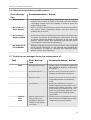
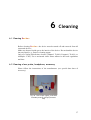
1
User Manual
Sentiero, Software Revision 1.4
Manual Sentiero
Produced by PATH medical GmbH, Germering, Germany.
Printed on paper, which was produced without chlorine bleaching.
Revision 8, Valid since Firmware Version 1.4, November 2011.
Copyright
© 2011 PATH medical GmbH
Reprint – even partially – only allowed with written notice from PATH medical GmbH.
Article number: 100158
Contact: [email protected], +49 89 8007 6502
All mentioned items, products, brands and trademarks are registered/owned by the mentioned
companies.
This manual and mentioned technical details are subject to change. The latest information and
revision is available online: www.pathme.de → support.
Errors and omissions excepted.
Contact information from your distributor, contact information from your service partner:
Table of contents
1 Scope of application
5
2 Remarks, used symbols
7
2.1
2.2
2.3
2.4
Notes on safety .............................................................................. 7
Notes on operational concept ............................................................. 8
About this manual and further sources of information .................................. 8
Symbols and structure of the graphical user interface ................................... 9
3 Start, reset, charging, and connecting sockets
23
3.1 On / off switch - special function for showing footer .................................. 23
3.2 Hardware reset – device is stalled ........................................................ 24
3.3 Connecting to the sockets of the device ................................................. 24
3.3.1 Sentiero ................................................................................. 24
Red socket ................................................................................... 24
Blue socket ................................................................................... 25
Grey socket ................................................................................... 25
USB socket ................................................................................... 26
3.3.2 Sentiero-A ............................................................................... 27
Blue, white and red socket ..................................................................... 27
3.4 Charging the device and and connecting to the label printer .......................... 27
Power supply ................................................................................. 27
Connect to label printer ........................................................................ 28
4 MIRA – PC software and updates
4.1
4.2
4.3
4.4
Range of functions of the MIRA PC software .......................................... 29
How to get MIRA ......................................................................... 29
How to get updates ........................................................................ 29
MIRA - FAQ ............................................................................... 30
5 First steps
5.1
5.2
5.3
5.4
5.5
5.6
5.7
29
31
User / patient selection .................................................................... 31
Device settings ............................................................................ 32
Hardware tests and possible error messages ............................................ 32
System information and demo mode .................................................... 34
License management and upgrades ...................................................... 34
Other errors and their possible reasons .................................................. 35
Possible error messages during the measurement of… ................................. 35
6 Cleaning
37
6.1 Cleaning Sentiero ......................................................................... 37
6.2 Cleaning of ear probe, headphone, accessory .......................................... 37
6.3 Cleaning and disinfection of the ear probe calibration cavity ......................... 38
7 Warranty, repair and service
39
7.1 Warranty ................................................................................... 39
7.2 Repair ...................................................................................... 39
7.3 Service, routine maintenance ............................................................. 40
8 Accessories
41
9 Technical specifications, standards, manufacturer’s data
43
9.1 Device classification and applied standards ............................................. 43
9.2 Device, storage, transport ................................................................. 44
Device ........................................................................................ 44
Power supply / rechargeable battery ............................................................ 44
Storage and transport .........................................................................44
9.3 Modules .................................................................................... 45
MAGIC ...................................................................................... 45
PTA4 ......................................................................................... 45
PTA4 Extended ............................................................................... 45
PTA3 ......................................................................................... 45
PTA-HF ...................................................................................... 45
SUN .......................................................................................... 45
MATCH (Mainzer 1a) ......................................................................... 46
MAUS ........................................................................................ 46
DPOAE (Quick mode) ......................................................................... 46
DPOAE (Threshold mode) ..................................................................... 46
TEOAE ....................................................................................... 46
ABR .......................................................................................... 46
9.4 Accessories ................................................................................ 47
9.5 Electromagnetic compatibility report (EMC report) .................................... 47
Made in Germany by PATH medical GmbH ............................................ 52
4
1
Scope of application
Sentiero offers both psycho-acoustical and physiological test procedures. This
includes conventional and image-based pure-tone audiometry, speech (logatome)
intelligibility, auditory brainstem responses (ABR) and otoacoustic emissions. The
usage of Sentiero should be supervised by qualified personnel.
Sentiero is designed for:
1. Diagnostics, monitoring and follow-up after newborn hearing screening
2. Pre-school, school, and adult hearing screening (pure-tone threshold and speech
intelligibility)
3. ENT diagnostics
- Confirmation of a cochlear hearing loss or a neural hearing loss
- Topological diagnostics
- Monitoring of cochlear function after noise exposure or ototoxic drug administration
- Identifying patients who are simulating a hearing loss
- Proof of a noise-induced hearing loss for medical opinions
- Pediatric audiology
OAEs are not present in ears with sound-conductive hearing loss, since both the
stimulus and the response amplitude are reduced due to the damping of the middle
ear. Before starting the measurements, please make sure that any noise or other
distracting factors are eliminated.
A separate room with little ambient noise should be available for measurements
with Sentiero.
Criterion of exclusion
Sentiero must not be used in cases of external otitis (outer ear canal infection) or in any case which yields to pain when inserting the ear probe.
5
1 Scope of application
6
2
Remarks, used symbols
2.1 Notes on safety
This manual includes notes on safety, which need to be followed in order to allow
the correct usage of Sentiero .
Warning: The following situations may cause harm or may be dangereous for
patient or user.
If Sentiero is used during a surgery, the ear probe and all connectors must not
have contact to any conductible objects including grounding. During usage of HF
surgery devices Sentiero must not be used.
During usage of defibrillators Sentiero must not be used.
The connector sockets are intended for connecting to the proper plugs of the original acessories as decribed in section 3.3. Other devices must not be connected.
During measuremens with Sentiero, the serial transfer cable or the label printer
cable must not be connected.
Strong electromagnetic radiation may affect the operability of the instrument. Do
not use Sentiero nearby devices with strong electromagnetic radiation. Please
refer to the suggestions in section 9.5.
Cleaning instructions are described in chapter 6. Acessories' cleaning instructions
are described on the respective data sheets.
Following art. 1, §18 and Art. 2 of the law concerning the rearrangement of waste
legislation product stewardship for batteries and rechargeable batteries from June
25th 2009:
The device includes a NiMH rechargeable battery pack.
In case the rechargeable battery pack cannot be charged anymore, the
rechargeable battery pack must be replaced by an authorized distributor. The dis-
7
2 Remarks, used symbols
tributor is responsible for the correct disposal and storage. In case of disposal of
the device, the device is not intended for consumer waste but for special waste.
A fully charged and completely functional battery pack will allow for measurements of up to 6 to 8 hours (dependent on usage).
2.2 Notes on operational concept
After turning on the device, Sentiero can be operated via a touch-sensitive display (touch screen) providing several menus and functions. Context-sensitive help
screens, which explain the currently available symbols and their functions, allow
an intuitive handling of the hand-held device. The context-sensitive help screens
are available via the blue information icons, which are displayed on each screen in
the footer at the right-hand side.
At some screens, there is an additional information icon, which will provide further information for the user.
2.3 About this manual and further sources of information
In this manual you will find information about the handling of the device as well
as information about the operation and cleaning. Further information and details
about the measurement modules, potential clinical applications and recommendations for combining several test procedures are explained in the guide for practical
application (How-To Manual). You can download this manual from
http://www.pathme.de/support/.
8
Symbols and structure of the graphical user interface
2.4 Symbols and structure of the graphical user interface
All screens contain three basic elements: the header, the main screen, and the
footer.
header
main screen
footer
Fig. 1: Screen layout
The following table will provide an overview of all symbols and their corresponding function. The symbols are sorted by their appearance in one of the above elements: header, main screen and footer. The functions are also explained in the
context-sensitive help on the device.
Symbols header
header
structure
Meaning
Current time
menu / patient
name
e.g. 11:44
settings
battery level
indicator
charging symbol
Battery level indicator:
green - sufficient power available
red – charging needed.
Battery is charged.
Battery is fully charged – mains operation.
Patient search pattern is active;
Search pattern (flter) can be changed/deleted via
magnifying glass symbol (footer).
9
2 Remarks, used symbols
Symbols header
Meaning
USB connected.
Special symbols for
MAGIC
Stimulus information is listed (coded) within the
header. This can be deselected (hidden stimulus
information) in the settings menu. Active stimulus
conditions are displayed on the left, whereas information about the last recording (patient input) is
displayed on the right. For further information
please refer to the How-To Manual.
F/S
Frequency modulated tone / sine tone.
I/M
Instruction phase / Measurement phase.
R / L / b-R /
b-L
Current stimulation at ___ ear
R: right ear
L: left ear
b-R: Right ear (measurement of both ears selected)
b-L: Left ear (measurement of both ears selected).
40 dB
mute
Indication of current stimulus level (40 dB HL).
Indication of a test with a muted stimulus.
e.g. 40
Information about previous patient response: last
stimulus level in dB HL (e.g. 40), patient input:
tone was heard.
e.g. 60
Information about previous patient response: last
stimulus level in dB HL (e.g. 60), patient input:
tone was not heard.
mute
mute
Symbols footer
Footer
structure
Patient indicated to hear a sound after presentation of a muted stimulus. Low attentiveness could
be the reason for this behavior.
For these responses, the respective test frequency
is marked in the audiogram with a question mark
(MAGIC audiogram mode only) together with the
total of such events (mute - “heard”).
“Not heard” patient response after presentation of
a muted stimulus.
Meaning
Back / home /
turn off
Turn off the device.
10
diverse
symbols
info
Symbols and structure of the graphical user interface
Symbols footer
Meaning
Context-sensitive help, info.
Specifc information available – slideshow on
selected topics.
Parameter settings (global or test-specifc). Previously entered settings are stored for further measurements under same test conditions → individual
protocols possible.
Search patient (last name).
Add a new patient.
Measurement with anonymous patient (please
note that data is not stored after measurement).
Back to previous menu;
Cancel data entry.
Scroll through
screen).
pages
(e.g.
patient
list,
help
Confrm data entry.
Enter space character.
Backspace. Delete character.
The content of the edit-window can be selected
(red).
11
2 Remarks, used symbols
Symbols footer
Meaning
Changing between numerics, letters or special
characters.
Date input:
increase number
decrease number.
Back to patient list.
Back to main menu (i.e. test selection).
Print test results from the test view menu (PRINTER module needed).
View results of stored measurements of the selected patient.
MAGIC Test
Special symbols during MAGIC test:
Refll animal rack.
Undo previous patient response.
PTA Test
Special symbols during PTA test:
Stimulus output on right ear (red).
Stimulus output on left ear (blue).
12
Symbols and structure of the graphical user interface
Symbols footer
Meaning
Confgure level shift control: shift sine level only,
shift masking noise level only or simultaneously
shift sine and masking noise level (locked mode).
Shift sine level.
Shift masking noise level.
Simultaneously shift level of sine tone and masking noise (locked mode).
OAE / ABR
Special symbols during OAE tests:
Abort test.
Resume paused test.
Pause test.
Skip measurement at current stimulus setting and
proceed with the measurement at the next stimulus setting.
Activates edit mode for ABR result.
Peak Markers (Jewett I, III, V) can be set.
SUN
ning
Trai-
Special symbol during SUN Training test:
The training phase can be switched to test mode
immediately. The symbol is in the hidden footer,
which can be shown by pressing the on / off switch
of the instrument (see Fig. 2). In test mode, all logatomes are presented with increasing noise level
in order to test speech understanding in noise.
13
2 Remarks, used symbols
Symbols in the
main screen
Meaning
Image-based, self-controlled pure-tone audiometry
for children from 3 years on. There are two test
types: MAGIC Audio and MAGIC Screen. The footer
will be removed when using MAGIC (see 3.1).
Advices of how to instruct children to perform the test as well as more details of the
measuring procedure can be found in the
How-To Manual / Chapter 2 'MAGIC'.
MAGIC audiometry mode: Frequencies from 250
Hz to 8 kHz, initial stimulus level and stimulus
type can be chosen.
MAGIC screening mode: Frequencies from 250 Hz
to 8 kHz, screening level and stimulus type can be
chosen.
Conventional pure-tone audiometry following ISO
60645-1: Class 4 (screening up to 70 dB HL) or
class 3 (diagnostic up to 100 dB HL for air- and
bone-conduction; insert sound probes, patient
response switch,contralateral masking, stimulus
selection).
For more details about measuring procedures see How-To Manual / Chapter 3 'PTA'.
Screening test for assessing speech intelligibility
in noise in school children and adults. Vocal-Consonant-Vocal logatoms are used. The test is available for different languages (I, D, E, F). The
screening level can be chosen between 50 and 70
dB HL. Sound presentation is available via headphones, insert earphones or free-feld loudspeakers.
For more details about the measuring procedure see How-To Manual / Chapter 5 'SUN'.
In training mode, all logatomes are presented
without noise. This is intended for instructional
purposes.
In test mode, all logatomes are presented with
increasing noise level in order to test speech
understanding in noise.
Additional speech tests are available on this
instrument.
14
Symbols and structure of the graphical user interface
Symbols in the
main screen
Meaning
Image based speech test for children. In German
language – adaptation to other languages after
request.
Screeningtest for auditory processing disorders
(MAUS). Validated in German language - adaptation to other languages after request.
Otoacoustic emissions are elicited with clicks
(TEOAEs) or tones (DPOAEs). Measurements have
to be performed in a quiet environment. Correct
probe placement is checked by calibration phase
before measurement phase.
Three DPOAE measurement types are available in
two separate modules.
For more details about the measuring procedures see How-To Manual / Chapter 4
'OAE'.
Automated hearing threshold estimation is done
by using extrapolated DPOAE I/O-functions. This
patented method uses a special stimulus setting
for eliciting DPOAEs and presents cochlear function in the form of an audiogram. Test frequencies
can be chosen between 1.5 kHz and 8 kHz.
User defned DPOAE measurement at frequencies
between 1.5 kHz and 8 kHz at different levels from
25 dB HL to 50 dB HL in steps of 5 dB. Single and
multiple selection of stimulus parameters enable 2
different types of protocols: screening and individual diagnostic measurements.
TEOAE are analyzed in a time window of 5 to 13
ms. There are two TEOAE measurement types
available in one combined module: TEOAE Quick
and TEOAE Diag.
For more details about the measuring procedures see How-To Manual / Chapter 4 'OAE'.
TEOAE measurement is done by using an automated, statistical algorithm for response detection
(valid/invalid). TEOAEs are shown in time and frequency domain. Artefact ratio and stability of the
stimulus are displayed.
If two ear probes are connected (to red socket and
blue socket), the measurement can be conducted
simultaneously in both ears (binaural).
15
2 Remarks, used symbols
Symbols in the
main screen
Meaning
TEOAE measurement is done by using user
defned criteria for response detection in 3/5, 4/5,
and 5/5 different frequency bands (1,1.5, 2, 3 und
4 kHz). For each frequency band different minimum SNRs (3, 6, and 9 dB) can be chosen. Results are presented in time and frequency domain
or in table format. Artefact ratio and stability of
the stimulus are displayed as well as the chosen
detection criteria.
Auditory Brainstem Responses (ABR) / evoked
potentials are elicited by click or chirp stimuli.
They are recorded with electrodes (see accessory
electrode cable).
When starting the measurement, the impedance
of the electrodes is measured and monitored during measurement.
For more details about the measuring procedures see How-To Manual / Chapter 5
'ABR'.
…
Symbols of
result view
Five individual (different) protocols can be confgured and maintained on the instrument. The
preset name can be edited for each setting.
Parameters are:
Click, chirp, polarity, (frequency-)jitter, masking,
auto-proceed, auto-stop, stimulus level (up to 5
traces from 5 to 90 dB nHL), rate, averages,
recording window, age group (norm values).
The test results shall always be interpreted by an
expert. The following symbols are only meant as
visual indicators and thus do not imply any diagnostic recommendation.
Test result OK.
Test result not OK.
Test result needs to be seen in detail to decide if
OK (e.g. aborted measurement). Result might be
in-between OK and not OK.
16
Symbols and structure of the graphical user interface
Symbols in the
main screen
Test names
and layout
Meaning
The following abbreviations are used for the different test results:
MAGIC (Audiogram mode)
PTA (Audiogram)
SUN (Speech under Noise – screeningtest)
MAUS (Auditory processing disorder – screeningtest)
MATCH (Image based speech test for children)
TEDIAG (TEOAE Diagnostic)
DPDIAG (DPOAE Quick Test with multiple test
levels)
DPTHRES (DPOAE Threshold)
SUN (Score result)
Screening tests/modes are given with a 3-letter
abbreviation and the stimulus level:
MAG45 (MAGIC Screening at 45 dB HL)
DPQ35 (DPOAE Quick Test at 35 dB HL)
Additionally, the tested ear (right, left), the date
and time of the measurement, and a visual indicator of the test result is given.
Additional
symbols
To start a measurement, change settings...
Start test with right ear.
Start test with left ear.
Start test for both ears (binaural or serial processing right and left ear).
Decrease value (e.g. frequency, level).
Increase value (e.g. frequency, level).
Check box: multiple selections possible.
17
2 Remarks, used symbols
Symbols in the
main screen
Meaning
Radio button: single selection from the radio button group possible.
MAGIC Test
Special symbols used in MAGIC test:
Restart instruction phase.
Hide stimulus information in header
toggles between hide and show).
(button
Show audiogram (intermediate result).
Different animals in the MAGIC test represent different frequencies.
e.g.
Tone on (while button is pressed).
e.g.
Animal with scarf: response symbol for tone “not
heard”.
e.g.
Animal without scarf: response symbol for tone
“heard”.
e.g.
Repeat MAGIC audiogram test at selected frequencies.
If a “muted stimulus” was “heard”, this might be
an indicator for reduced attentiveness. The number of these “wrong” responses is shown in audiogram mode at the respective frequency beside the
question mark symbol. The measurement at these
frequencies should be repeated.
?
2
18
Symbols and structure of the graphical user interface
Symbols in the
main screen
PTA Test
Meaning
Special symbols during PTA test (Pure Tone
Audiometry):
The stimulus is presented as long as the loudspeaker button is pressed.
Decrease / Increase level.
Stimulus / Noise indicator: Lights highlighted as
long as the stimulus (orange light) or noise (green
light) is presented.
Patient response indicator: if the patient response
button is pressed the indicator is highlighted
(green light).
The threshold at the crosshairs can be set by
clicking on the audiogram.
Use continuous sine tone as stimulus.
Use pulsed sine tone as stimulus.
Use warble tone as stimulus.
Use air conduction.
Use bone conduction placed at the forehead.
19
2 Remarks, used symbols
Symbols in the
main screen
Meaning
Use bone conduction placed at the mastoid.
OAE Tests
The following symbols are only meant as
visual indicators and thus do not imply any
diagnostic recommendation. Please note
that the results are subject to the inherent
accuracy of the test method (see How-To
Manual / Chapter 8 'OAE'):
Valid response.
Invalid response.
The test at this stimulus setting was skipped. No
result available.
DPOAE
Threshold
The cochlear threshold is calculated from
DPOAE growth functions using a patented
algorithm. The following symbols are used:
Complete threshold estimation for the right (red
circle) or left (blue cross) ear based on patented
algorithm.
Threshold estimation is performed via analysis of
the lowest stimulus level which produced a valid
DPOAE (right ear: red; left ear: blue).
No valid DPOAE available at this frequency – the
threshold is likely to be above 50 dB HL (right ear:
red; left ear: blue).
Grey symbols indicate that at one or more stimulus settings the measurement was skipped.
20
Symbols and structure of the graphical user interface
Symbols in the
main screen
Meaning
ABR Test
Edit preset name
Select a waveform (here level 30 is chosen) in
order to navigate the peak marker.
The Jewett I, III oder V can be selected and set
manually by direct navigation (tip on peak of
curve) or by using the navigation arrows.
The marker can be validated by the green o.k.symbol (it will change color from black to green).
Latencies are calculated and displayed (table in
result view).
Result view for ABR.
The scaling of the waves can be changed by sliding with one fnger over the graphic area. Sliding
down zooms out, sliding up zooms in. The scale is
adjusted accordingly.
Tipping onto the result view area (latencies) changes the displayed information from:
latencies → parameters used → impedances and
residual noise
21
2 Remarks, used symbols
22
3
Start, reset, charging,
and connecting sockets
3.1 On / off switch - special function for showing footer
Special function
during MAGIC
and SUN module:
on / off
(turn off device: press switch for
10 seconds or touch the “off”
symbol on the display ( footer).
when pressing
the on/off switch
the footer will be
shown. Otherwise
the footer
disappears.
Fig. 2: On / off switch on the right-hand side of the
device; special functionality during MAGIC and SUN
module.
23
3 Start, reset, charging, and connecting sockets
3.2 Hardware reset – device is stalled
Push the reset button
below the rubber
casing on the back
side of the device
with a pen.
Afterwards the
device can be turned
on with the on switch.
Fig. 3: Black reset button on the back side of
the device below the
red rubber casing
3.3 Connecting to the sockets of the device
3.3.1 Sentiero
Ear probe (for
OAE
measurements)
plug with red
tension relief.
Red socket
Fig. 4: Blue, grey and red
socket
Fig. 5: OAE probe
(TE: grey and DP:
red) with red tension
relief
24
Connecting to the sockets of the device
Headphone (for
audiometry) plug
with blue tension
relief
Blue socket
Fig. 6: Blue, grey and red
socket
Fig. 7: Free field
loudspeakers JBL
Control 2
Fig. 8: GN otometrics insert earphones
Fig. 9: Headphone Interacoustics DD-45
Fig. 10: Headphone Holmco
PD-81
Fig. 11: Headphone Sennheiser
HDA 280
Fig. 12: Sennheiser HDA 200 (HF Audiometry)
Grey socket
Patient response
switch, bone
conductor or
charger plug with
grey tension relief
and labelprinter are
to be connected to
the grey socket.
Fig. 13: Power supply and
charging cable with grey tension relief
25
3 Start, reset, charging, and connecting sockets
Fig. 14:
Patient
response
switch
Fig. 15: Patient response
switch combined with bone
conductor
Fig. 16: power plug
Fig. 17: Labelprinter
USB socket
The USB socket is
located at the
bottom part of the
device
Fig. 18: USB - socket
Connect the handheld device via a USB cable to your PC in order to update the
device firmware or to exchange measurement data with the MIRA PC software
(see Chapter 4).
26
Connecting to the sockets of the device
3.3.2 Sentiero-A
Blue, white and red socket
Patient response
switch, ABR
(electrode) cable, label
printer or power are to
be connected to the
white socket.
Headphones, inserts
and freefield cable are
connected to the blue
socket as well as the
second ear probe for
binaural TE Quick
measurement.
Ear probe
(for OAE-measurement)
or bone conductor are to
be connected to the red
socket.
Fig. 19: Blue, white and red socket.
Fig. 20: ABR (electrode)
cable
Sentiero-A can be used for ABR measurements (module ABR, see license management).
Basing on the security concept for ABR measurement, minor differences can be found in the
accessories in comparison to Sentiero's acessories: ABR (electrode) cable, power plug, patient
response switch, bone conductor and label printer cable.
All the other accessories can also be used in Sentiero.
3.4 Charging the device and and connecting to the label printer
Power supply
Connect the charging cable as seen in Fig. 13 (or Fig. 19) to the device. For charging the device, connect the power plug to a power socket with appropriate output
voltage and frequency (see data on charger). The charging process starts automatically and is finished within 2 hours.
27
3 Start, reset, charging, and connecting sockets
Connect to label printer
When using the PRINTER module (see license management, section 5.5), you are
able to print the test results directly from the device (View test menu). Therefore
you need the Seiko Smart Label Printer 440 or 450 as well as a special connector
cable to the device (Art. nr. 100 189). Please connect the cable to the device as
pictured in Fig. 13 (or Fig. 19).
The label printer must be connected to the device only with this special connector
cable in order to maintain patient safety and integrity of the medical device.
28
4
MIRA – PC software and
updates
4.1 Range of functions of the MIRA PC software
Irrespective of the installed licenses (i.e., modules) on the device, with the MIRA
PC software you are able to update your device firmware. For updating your
device firmware please connect the device via USB to your PC.
Devices which have the SW-COM module enabled (license) additionally can
transfer data between the device and the PC. MIRA PC software simplifies data
analysis, enables user configuration, and allows adding comments to patient and
test data. Various report options simplify documentation (office printer). Please
note that MIRA does not provide any additional diagnostic function.
4.2 How to get MIRA
The latest MIRA PC software and its corresponding manual are available via
download on the PATH medical homepage.
Url: http://www.pathme.de/support
4.3 How to get updates
New device firmware and PC software updates will be posted each April and
October on the PATH medical homepage.
Url: http://www.pathme.de/support
If any additional updates are available, the distributors will be informed. The distributors are supposed to inform the end customers.
29
4 MIRA – PC software and updates
4.4 MIRA - FAQ
30
Question
Answer
How to disable USER
MANAGEMENT on the
instrument?
Login into MIRA
Section system setting → user management
on instrument (uncheck).
How to update the
instrument's frmware
using MIRA?
Login into MIRA and import latest frmware
(available
on
PATH
Homepage
Url:
http://www.pathme.de/support) by pressing
'Firmware' button. → select folder and confrm. Alternatively: download latest version
of MIRA, which has the latest frmware
already included.
After that, connect instrument with PC
(USB) and press 'Update' button.
The instrument and the PC shall not be disconnected (see display of instrument). The
instrument must have enough energy (full
battery) or must be connected to mains.
All users are deselected – including ADMIN
user. No login possible.
Reset the Admin account by starting the
Recovery-Console. This program is installed
in the same program folder as Mira.
Password: Stargate.
What's the initial password?
1234
How to get more information and help on
MIRA?
MIRA contains an online help function.
Additional information can be found in the
MIRA manual on the PATH support page
Url: http://www.pathme.de/support
5
First steps
5.1 User / patient selection
After turning on the device, you will be asked either to select a user or to select an
existing patient or create a new patient data set. Dependent on your application
situation it may be useful to activate or deactivate the user management (see Fig.
21 / 22). With the MIRA PC software (see Chapter 4) you are able to (de-)activate
user management and to create different user profiles with or without password,
which can be uploaded to the device.
If you need further information please use the context-sensitive help on the device
(i.e., press the info icon in the footer).
Note:
It is assumed that one user will usually login and work with the device until turning off the device. Hence, changing a user is possible by turning off and on the
device.
Global
parameters:
(device)
settings
Fig. 21: Initial screen if
no password was assigned or after login
Fig. 22: Patient list if
patient data had been
generated
31
5 First steps
5.2 Device settings
The following settings can be changed on the device (see Fig. 22: global parameters):
•
Date / Time (including date and time format: e.g. DD.MM.YYYY or
MM/DD/YYYY)
•
Language (selection out of several languages dependent on the installed
language pack, i.g. E,D, I, ESP, F)
•
Sound / Brightness
•
Hardware tests
•
Delete data (data will be removed from device – to restore data, do not
delete before transferring data to the PC - see Chapter 4)
•
System information
5.3 Hardware tests and possible error messages
Device self
test
Error message
Recommendation / Action
Battery /
Core voltage
Please contact your distributor.
Codec
Please contact your distributor.
SDRAM
Please contact your distributor.
All tests
Selftest was successful. Status o.k.
Probe test
In order to conduct a probe test, use either the red test cavity (test cavity for probe
tip A, Article nr. 100 129) for testing the big probe tip OR the blue test cavity
(test cavity for probe tip S, Article nr. 100 160) for testing the small probe tip.
Connect the probe (WITH probe tip but WITHOUT ear tip) into the test cavity.
Please verify correct placement. Press 'Probe Test' to start the test.
Please use only the big probe tip together with the red (big) cavity. Please use the
small probe tip together with the small (blue) cavity.
Please use only the big ear tips together with the big probe tip during measuremnts and the small ear tips together with the small probe tip. Wrong combination of
ear tip and probe tip will deteriorate your results. See also advice in the accessory
box. If in doubt about what combination is correct, please contact your service
partner.
32
Hardware tests and possible error messages
Probe test
Error message
Recommendation / Action
No probe
found
Please check if the probe is
connected to the device. If it
is connected properly:
→ Probe could not be recognized, hardware error.
→ Please contact your distributor.
Probe failed
1) Is the probe placed inside
the red calibration cavity?
→ If not please use the calibration cavity
2) Are there one or two
smooth lines (red and blue)
and are these lines outside
the limit markers?
→ Please contact your distributor
3) Are there jagged lines
and are these lines below
the limit markers?
→ Please check if the probe
tip is clogged. Change the
probe tip and conduct the
probe test once again. If
there is still no valid result
→ please contact your distributor.
33
5 First steps
5.4 System information and demo mode
Fig. 23: System
information with license
management and demo
mode
In the system information, general information about the device and firmware version is displayed. Information about connected transducers are also displayed
(connected before menu is entered). When contacting your distributor (error message, module update...) this data should be at hand.
You can activate the demo mode 15 times. In demo mode, you are able to use all
modules of your platform until the end of the day. If you are interested in upgrading your device with a specific module, please contact your distributor.
5.5 License management and upgrades
In order to update your license key (e.g., after buying a new module) you need to
press the “License No.” button on the System Information screen (see Fig. 23).
The already entered license key and all currently licensed modules are displayed.
If you would like to add other modules to your device please contact your distributor. You can use the demo mode to evaluate the need for additional modules for
your device (see section 5.4).
From the distributor you will receive a new license key to be installed on your
device. Before installing a new license key, please make sure to have the former
license key available in written (e.g. on delivery note) for potential reinstallation if
needed.
Install a new license: Press the “Enter license key” button, enter your new license
key and confirm the input by pressing the “ENTER” key.
34
Other errors and their possible reasons
5.6 Other errors and their possible reasons
Error description
Recommendation / Action
Black display.
The display is automatically deactivated after 2 minutes
without user activity in order to increase use time without
recharging. Please touch the display in order to leave the
power saving mode.
No feedback,
black display
After 5 minutes without user activity the device automatically powers down completely. Please start the device by
pressing the on-switch.
No feedback,
display stalled.
If the device does not respond to user action you might need
to restart the device by pressing the reset switch (see Fig.
3). Please charge the battery if necessary. If the error is still
present, please contact your distributor and describe which
circumstances resulted in this behaviour.
My language is
not available.
Multiple language groups are offered. Within each language
group several languages can be selected and changed during operation. In order to changing the language group,
please contact your distributor.
5.7 Possible error messages during the measurement of…
Test
OAE
MAGIC,
PTA,
SUN
Error description
Recommendation / Action
Wrong probe for test.
Please check if a valid ear probe (EPDP or EP-TE) is properly connected to
the device.
No probe found.
Please check if a valid ear probe is
properly connected to the device.
Remove cable.
Please remove the connector cable
of the label printer or the RS232
cable.
Incomplete.
Ear probe calibration is invalid.
Please replace the ear probe in the
patient’s ear. When necessary, check
if the probe tip is blocked (e.g. cerumen) and eventually replace it. Conduct a probe test (Settings, Hardware tests).
Please make sure to
have exactly one
transducer type connected to the proper
connector.
Please connect a headphone to the
blue socket and if applicable a bone
conductor to the grey socket.
35
5 First steps
36
6
Cleaning
6.1 Cleaning Sentiero
Before cleaning Sentiero the device must be turned off and removed from all
connected devices.
Make sure that no liquids get to the interior of the device. Do not dunk the device
into any liquid, e.g., water or cleaning agents.
Only use wiping disinfection cleaners (Ethanol: 70-80%, Propanol: 70-80%, or
Aldehyde: 2-4%). Use a moistened cloth. Please adhere to the local regulations
and laws.
6.2 Cleaning of ear probe, headphone, accessory
Please follow the instructions of the manufacturer (see special data sheet of
accessory).
Fig. 24: Test coupler (right), probe with
mounted probe tip, ear tips (accessories)
37
6 Cleaning
6.3 Cleaning and disinfection of the ear probe calibration cavity
The calibration cavity (see Fig. 24) for the ear probe test must be used with a
desinfected and clean new probe tip. In case of contamination with pathological
material or suspected dirt inside the cavity, do not reuse the calibration cavity. Do
not use cleaning liquors or vapour sterilization! For external cleaning, please use a
sterile alcohol wipe, typically containing isopropyl alcohol 70%. Please refer to
the manufacturer's data sheet for the minimum time period in which the wipe has
to be in direct contact with the surface to ensure the effectiveness of the cleaning.
38
7
Warranty, repair and
service
7.1 Warranty
After the date of shipment of Sentiero, a warranty period of one year is provided
for the device. Warranty includes material and labor costs and has to be in accordance with the manufacturer specifications.
For the rechargeable battery pack, the touch screen and wearing parts, a six
months period of warranty is provided. The warranty is only valid for devices purchased from an authorized distributor.
Warranty procedure: Inform your distributor about the defect. Send the device
together with an error description to your distributor. Mailing expenses are not
refundable and are to be paid by the customer. Please send the device in its original packaging to your distributor!
Warranty is not applicable in cases of breakage, malfunction due to manipulation or unintended usage, negligence, nonobservance of cleaning instructions,
crashes or accidents, damages due to shipment. Warranty is also not applicable
when the device is not used according to manufacturer’s instructions.
7.2 Repair
In case Sentiero is defect or differs in any way from its original setup, an authorized distributor will repair, re-calibrate or exchange the device. Service features
and repairs of the device and its electro-medical accessories must only be conducted by the manufacturer or its authorized service partners. The manufacturer reserves the right to decline any responsibility for the safety in operation, reliability,
and capability of the device if any service features or repairs were conducted by a
non-authorized body. If in doubt, please contact the manufacturer before making
your service partner repair the device.
39
7 Warranty, repair and service
7.3 Service, routine maintenance
Declaration:
The measurement principle of otoacoustic emissions is not explicitly described in
§11 of the medical device operator act (Germany, EU). Therefore, the manufacturer is obliged to define metrological inspection instructions.
Calibration:
For all device types of the Sentiero device group, an annual metrological
inspection following §11 Clause 2 of the medical device operator act must be
conducted by a service partner which is authorized by the manufacturer.
Note: For the PTA module an annual inspection period is stipulated by the
European standard EN 60645-1.
Explanation:
In the Sentiero device group including its accessories (e.g. ear probe), there are
parts, which are exposed to pressure, moisture, temperature, and contamination. In
order to ensure accurate measurement operability, the fault tolerance provided by
the manufacturer needs to be controlled by specificly designed instrumentation
and defined procedures. Therefore, the metrological inspection must be conducted
by authorized service partners who were instructed and trained by the manufacturer. The annual metrological inspection is established following the regulations
for audiometers (see EN 60645-1).
40
8
Order Nr.
Accessories
Articles (selected)
100 135
Accesory box (Adult, big probe tip and big ear tips)
100 296
Acoustic earmuffs (Peltor)
100 119
Bone conductor Set (Bone conductor + Patient
response switch + Firmeware PTA 3)
100 214
Bone conductor with patient response switch BCRE1 (available for PTA class 3 and PTA class 4
extended only)
100 083
Charger Senti / Sentiero
100 268
Charger Sentiero Advanced
100 028
Ear probe EP-DP
100 120
Ear Probe EP-TE
100 063
Ear tip ET-03 (5.0 mm)
100 064
Ear tip ET-10 (with fns 6-10mm)
100 125
Ear tip ET-11 (with fns 12-16 mm)
100 058
Ear tip ET-12 (soft tip 14 mm)
100 144
Ear tip ET-13 (10 - 12 mm)
100 230
Ear tip ET-14 (soft tip 18 mm)
100 251
Free feld cable
100 297
Free feld loudspeaker Set (JBL Control 2)
(loudspeaker + cable)
100 117
Headphone HP01 (Sennheiser HDA-280)
100 118
Headphone HP02 (Holmco PD81 circumaural)
100 282
Headphone HP03 (DD-45, similar to TD39)
100 273
Insert earphones (GN otometrics)
100 199
Label printer cable Senti / Sentiero
100 189
Label printer with printer cable
100 169
Patient response switch
100 013
Probe tip A (for children and adults) PT-A
41
8 Accessories
Order Nr.
42
Articles (selected)
100 014
Probe tip S (for newborns) PT-S
100 089
Sentiero USB cable
100 088
Serial interface cable SC1 for Senti
100 162
Serial USB converter
100 129
Test coupler (calibration cavity)
100 151
Visual inspection tool for probe tip (cleaning tool)
100 347
Pure Tone Audiometer Class 3
(incl. bone conductor + pat. Button) for Sentiero
Advanced
100 342
Label Printer Seiko
(incl. cable + label printing SW)
100 030
Ear tip for probe tip S (4,5 mm)
100 031
Ear tip for probe tip S (5,0 mm)
100 032
Ear tip for probe tip S (Lamella 4,6-7 mm)
100 369
Probe Cable Clip (Clip for Ear Probe)
100 160
Test cavity for probe tip S (Test cavity for EP-DP
and EP-TE with Ear Probe Tip S blue)
100 207
Accessory Box E (Accessory Box Sentiero ECO fully
flled with all ear tip sizes type A)
100 261
Accessory Box P (Accessory Box Sentiero fully flled with all ear tip sizes type A + S for Pedaudiology)
100 269
Headphone SE ( Sennheiser HDA 200, calibrated,
incl. EEPROM (for high frequency audiometry)
100 286
Ear tip, Soft tip for insert Phone, Small
100 285
Ear tip, Soft tip for insert Phone, Standard
100 287
Ear tip, Soft tip for insert Phone, Jumbo
100 343
Patient button (Sentiero Advanced)
100 344
Bone conductor Radio Ear B71
(Sentiero Advanced)
100 341
Label Printer cable (cable for Senti/Sentiero to
Label Printer for Sentiero Advanced)
100 307
ABR Electrode cable (3 lead, shielded)
100 335
Electrodes, Foam ECG electrode with carbon snap,
43 x 45 mm, gel pad
100 334
Electrodes, Disposible Ag/AgCl EEG-EMG electrodes with clear adhesive gel
100 368
Electrodes, Blue Sensor P, single patient use.
9
Technical specifications,
standards, manufacturer’s
data
9.1 Device classification and applied standards
Device class IIa (according to Directive 93/42/EWG Appendix IX)
Application part BF
Directive 93/42/EWG concerning medical products (1993, modified by
2007/47/EG)
German Medical Devices Act (Medizinproduktegesetz MPG) (2002)
EN ISO 9001 (2008)
EN ISO 13485 (2010)
EN ISO 14971 (2009)
EN ISO 10993-1 (2010)
EN 60601-1 (2007)
EN 60601-1-2 (2007)
EN 60601-1-4 (2001)
EN 60601-1-6 (2010)
EN 60601-2-40 (1998)
EN 1041 (2008)
EN 980 (2008)
EN 60645-1 (2002) (Audiometry)
EN 60645-6 (2010)
EN 60645-7 (2010)
EN 389-1(2000) ,-2(1996),-3(1999),-4(1999)
EN 62304 (2007)
All laws, directives and standards apply in their latest version.
43
9 Technical specifications, standards, manufacturer’s data
9.2 Device, storage, transport
Device
Device dimensions: 209.3 x 98.0 x 34.8 mm
Weight (incl. Rechargeable battery pack and ear probe): 660 g
Real time clock
Rechargeable battery pack: duration of life > 2 years
Interfaces: RS232 up to 115 kbps; USB
Display: 240 x 320 pixel; graphic LCD 3.5”
Resistive touch screen
Up to five selectable languages per language pack
Power consumption: max 2 W (400 mA)
Power supply / rechargeable battery
Power supply: auto backlight control; automatic shutoff; double voltage control
Maximum operating time with fully charged batteries: 6 hours
Rechargeable battery pack: 4.8 V NiMH
Input voltage: 100-240 V – AC 47-63 Hz, 0.16-0.29 A
Output voltage: 8-11 V; DC 12 W max.
Maximum charging cycles: 500 - 1000
Maximum charging time: 2 hours
Storage and transport
Please keep the device in the provided carrying case in order to protect the device
and its accessories against external forces and environment impacts. Extreme storage and operating conditions may result in breakage of the touch screen display
(extremely low temperature) or in impairment of the device’s calibration.
Storage temperature: 0-40°C (32-104°F)
Operating temperature: 10-40°C (50-104°F)
Air humidity: 20-80% rel.
Air pressure: 900-1030 hPa
44
Modules
9.3 Modules
You will find further information with respect to the available modules in the
How-To manual.
MAGIC
Frequencies: 0.25, 0.5, 1, 2, 3, 4, 6, 8 kHz
Stimulus levels: 5 to 70 dB HL (in steps of 5 dB)
PTA4
Screening audiometer class 4 according to EN 60645-1
Frequencies: 0.25, 0.5, 1, 2, 3, 4, 6 kHz
Stimulus levels: 0 to 70 dB HL (in steps of 5 dB)
PTA4 Extended
Screening audiometer class 4 according to EN 60645-1 with extended
frequency/level range
Frequencies: 0.25, 0.5, 1, 2, 3, 4, 6, 8 kHz
Stimulus levels: -10 to max. 110 dB HL (in steps of 5 dB)
PTA3
Audiometer class 3 according to EN 60645-1
Frequencies: 0.25, 0.5, 1, 2, 3, 4, 6, 8 kHz
Stimulus levels: -10 to max. 110 dB HL (in steps of 5 dB)
PTA-HF
Only in connection with headphone Sennheiser HDA 200
extends PTA3 with frequencies: 9; 10; 11,2; 12,5; 14; 16 kHz
Stimulus levels: max 70 dB HL
SUN
Speech understanding in noise
Speech level: 50-70 dB HL (in steps of 5 dB HL)
Optional free field loudspeaker calibration via CCITT noise
Different languages (pronounciations of VCV) selectable: Italian, German (validated), French, English (in validation) – additional languages after request.
45
9 Technical specifications, standards, manufacturer’s data
MATCH (Mainzer 1a)
Image based speech test for children from 2.5 yrs on (via headphone, freefield,
insert earphones)
Stimulus level: 0 - 65 dB HL (step 1 dB)
Threshold estimation (SRT - Speech recognition threshold) with adaptive algorithm or discrimination loss estimation with fixed level.
MAUS
Copyright Westra Elektroakustik GmbH 2003/2004 – Details in separate manual.
Author A. Nikisch et al.
DPOAE (Quick mode)
Sample rate: 24 kHz
Frequency ratio f2/f1: 1.2
Level ratio L2/L1: scissor paradigm
Measurement interval: 512 samples
Frequencies f2 : 1.5, 2, 3, 4, 6, 8 kHz (single and multiple selections possible)
Stimulus levels L2 : 35 to 65 dB HL (in steps of 5 dB) (single and multiple selections possible)
DPOAE (Threshold mode)
Sample rate: 24 kHz
Frequency ratio f2/f1: 1.2
Measurement interval: 512 samples
Frequencies f2 : 1.5, 2, 3, 4, 6, 8 kHz (single and multiple selections possible)
Stimulus level L2 : 65 to 20 dB HL
Level ratio L2/L1: scissor paradigm (with automatic level optimization of L1)
TEOAE
Sample rate: 16 kHz
Stimulus level: ca. 80 dB SPL peak
Stimulus type: nonlinear click
Statistical stop criterion (TE Quick) or user-defined stop criterion (SNR: 3, 6, or 9
dB) in 3, 4, or 5 out of 5 frequency bands (1, 1.5, 2, 3, 4 kHz) (TE Diag)
Window of analysis: 5-13 ms post stimulus
ABR
Stimulus type: Click, broadband chirp,
Polarity: positive, negative, alternating
Level: 5 dB nHL - 90 dB nHL,(Single or multiple selection – up to 5 Level per
test sequence)
46
Modules
Rate: 10,0 Hz bis 89,9 Hz (Jitter),
Parameter:
Masking, Jitter, Auto Proceed, Auto Stop, 5 (editable) Presets
Recording, processing, storage
Window size: up to 30 ms
1.000 - 20.000 averages
Weighted averaging algorithm for artefact rejection
Continuous monitoring of electrode impedance
Display and storage of waveform, impendance, residual noise, averages, peak
marker (editable)
Stimuli:
Insert earphones, headphones
Future options:
Bone conductor
Ear probe
Frequency specific stimulus (Hi/Mid/Low Chirp)
9.4 Accessories
Accessories like e.g. headphones or insert earphones or electrode cables include
separate manuals / data sheets which contain important information.
9.5 Electromagnetic compatibility report (EMC report)
The EMC report certifies the conformity with respect to the mentioned requirements. Two reports have been issued by independent laboratories in 2009 and
2011. Sentiero can be used in an environment with electromagnetical radiation
as specified in the detail report (see fig. 26). The user shall take care, that the
device is used in an environment with minimum distances to potential radiators as
mentioned in fig. 27 (table with Nennleistung = effective power and Abstand =
distance, dependant on frequency of radiator /sender).
47
9 Technical specifications, standards, manufacturer’s data
Fig. 25: Copy of the electromagnetic compatibility (EMC) report, bilingual German / English, issued 2009
48
Fig. 26: Copy of electromagnetic compatibility detail report
49
9 Technical specifications, standards, manufacturer’s data
Fig. 27: Copy of electromagnetic compatibility detail report, distance to radiator/sender
dependant on frequency
50
This is a blank page due to production process. Take your notes here:
51
Made in Germany by PATH medical GmbH
Lorem Ipsum
DolorGmbH
PATH medical
Landsberger Straße 63
82110 Germering
Germany
Tel. +49 89 800 76 502
Fax +49 89 800 76 503
http://www.pathme.de