1
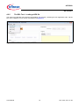
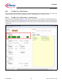
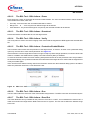
uIO-Stick
uIO-Stick
ePower BSL Tool
User Manual
Rev. 0.20, 2014-11-20
Automotive Power
uIO-Stick
Table of Contents
1
Introduction . . . . . . . . . . . . . . . . . . . . . . . . . . . . . . . . . . . . . . . . . . . . . . . . . . . . . . . . . . . . . . . . . . . . . 4
2
Overview . . . . . . . . . . . . . . . . . . . . . . . . . . . . . . . . . . . . . . . . . . . . . . . . . . . . . . . . . . . . . . . . . . . . . . . 4
3
3.1
Hardware Connection . . . . . . . . . . . . . . . . . . . . . . . . . . . . . . . . . . . . . . . . . . . . . . . . . . . . . . . . . . . . . 6
Hardware Connection Examples . . . . . . . . . . . . . . . . . . . . . . . . . . . . . . . . . . . . . . . . . . . . . . . . . . . . . 7
4
4.1
4.2
4.2.1
4.2.2
4.2.3
4.2.4
4.2.5
4.2.6
4.2.6.1
4.2.6.2
4.2.6.3
4.2.6.4
4.2.6.5
4.2.6.6
4.2.6.7
4.3
BSL Software . . . . . . . . . . . . . . . . . . . . . . . . . . . . . . . . . . . . . . . . . . . . . . . . . . . . . . . . . . . . . . . . . . . 9
uIO-Stick Firmware update . . . . . . . . . . . . . . . . . . . . . . . . . . . . . . . . . . . . . . . . . . . . . . . . . . . . . . . . . . 9
The BSL Tool . . . . . . . . . . . . . . . . . . . . . . . . . . . . . . . . . . . . . . . . . . . . . . . . . . . . . . . . . . . . . . . . . . . . 9
The BSL Tool - Basic Mode . . . . . . . . . . . . . . . . . . . . . . . . . . . . . . . . . . . . . . . . . . . . . . . . . . . . . . . . 9
The BSL Tool - The Expert Mode . . . . . . . . . . . . . . . . . . . . . . . . . . . . . . . . . . . . . . . . . . . . . . . . . . 10
The BSL Tool - The Configuration Dialog . . . . . . . . . . . . . . . . . . . . . . . . . . . . . . . . . . . . . . . . . . . . 12
The BSL Tool - Establish a Connection . . . . . . . . . . . . . . . . . . . . . . . . . . . . . . . . . . . . . . . . . . . . . . 13
The BSL Tool - Loading a HEX file . . . . . . . . . . . . . . . . . . . . . . . . . . . . . . . . . . . . . . . . . . . . . . . . . 15
The BSL Tool - BSL Actions . . . . . . . . . . . . . . . . . . . . . . . . . . . . . . . . . . . . . . . . . . . . . . . . . . . . . . 16
The BSL Tool - BSL Actions - Auto Execute . . . . . . . . . . . . . . . . . . . . . . . . . . . . . . . . . . . . . . . . 16
The BSL Tool - BSL Actions - Erase . . . . . . . . . . . . . . . . . . . . . . . . . . . . . . . . . . . . . . . . . . . . . . 17
The BSL Tool - BSL Actions - Download . . . . . . . . . . . . . . . . . . . . . . . . . . . . . . . . . . . . . . . . . . . 17
The BSL Tool - BSL Actions - Verify . . . . . . . . . . . . . . . . . . . . . . . . . . . . . . . . . . . . . . . . . . . . . . 17
The BSL Tool - BSL Actions - Protection Enable/Disable . . . . . . . . . . . . . . . . . . . . . . . . . . . . . . 17
The BSL Tool - BSL Actions - Run . . . . . . . . . . . . . . . . . . . . . . . . . . . . . . . . . . . . . . . . . . . . . . . 17
The BSL Tool - BSL Actions - Read Out . . . . . . . . . . . . . . . . . . . . . . . . . . . . . . . . . . . . . . . . . . . 17
The BSL Cmd - Command Line Tool . . . . . . . . . . . . . . . . . . . . . . . . . . . . . . . . . . . . . . . . . . . . . . . . . 18
5
Updates and Purchases . . . . . . . . . . . . . . . . . . . . . . . . . . . . . . . . . . . . . . . . . . . . . . . . . . . . . . . . . . 19
6
Revision History . . . . . . . . . . . . . . . . . . . . . . . . . . . . . . . . . . . . . . . . . . . . . . . . . . . . . . . . . . . . . . . . 20
User Manual
2
Rev. 0.20, 2014-11-20
uIO-Stick
List of Figures
List of Figures
Figure 1
Figure 2
Figure 3
Figure 4
Figure 5
Figure 6
Figure 7
Figure 8
Figure 9
Figure 10
Figure 11
Figure 12
Figure 13
Figure 14
Figure 15
Figure 16
Figure 17
Figure 18
Figure 19
uIO-Stick block diagram . . . . . . . . . . . . . . . . . . . . . . . . . . . . . . . . . . . . . . . . . . . . . . . . . . . . . . . . . . 4
uIO-Stick picture . . . . . . . . . . . . . . . . . . . . . . . . . . . . . . . . . . . . . . . . . . . . . . . . . . . . . . . . . . . . . . . . 5
uIO-Stick pin view . . . . . . . . . . . . . . . . . . . . . . . . . . . . . . . . . . . . . . . . . . . . . . . . . . . . . . . . . . . . . . . 6
uIO-Stick pin population . . . . . . . . . . . . . . . . . . . . . . . . . . . . . . . . . . . . . . . . . . . . . . . . . . . . . . . . . . 6
Normal LIN and FastLIN connection, without reset, target supplied by uIO . . . . . . . . . . . . . . . . . . . 7
Normal LIN and FastLIN connection, with reset, target supplied by uIO . . . . . . . . . . . . . . . . . . . . . 7
Normal LIN and FastLIN connection, with reset, target supplied by separate power supply . . . . . . 8
Direct connection of uIO-Stick to evaluation board, LIN-, FastLIN- and UART-BSL . . . . . . . . . . . . 8
BSL Tool - Basic Mode . . . . . . . . . . . . . . . . . . . . . . . . . . . . . . . . . . . . . . . . . . . . . . . . . . . . . . . . . . . 9
BSL Tool - Basic Mode . . . . . . . . . . . . . . . . . . . . . . . . . . . . . . . . . . . . . . . . . . . . . . . . . . . . . . . . . . 10
BSL Tool - Expert Mode . . . . . . . . . . . . . . . . . . . . . . . . . . . . . . . . . . . . . . . . . . . . . . . . . . . . . . . . . 11
BSL Tool - Configuration Button . . . . . . . . . . . . . . . . . . . . . . . . . . . . . . . . . . . . . . . . . . . . . . . . . . . 12
BSL Tool - Configuration . . . . . . . . . . . . . . . . . . . . . . . . . . . . . . . . . . . . . . . . . . . . . . . . . . . . . . . . 12
BSL Tool - no uIO-Stick found . . . . . . . . . . . . . . . . . . . . . . . . . . . . . . . . . . . . . . . . . . . . . . . . . . . . 13
BSL Tool - ready to connect to target system. . . . . . . . . . . . . . . . . . . . . . . . . . . . . . . . . . . . . . . . . 13
BSL Tool - Connected . . . . . . . . . . . . . . . . . . . . . . . . . . . . . . . . . . . . . . . . . . . . . . . . . . . . . . . . . . 14
BSL Tool - Load a HEX file. . . . . . . . . . . . . . . . . . . . . . . . . . . . . . . . . . . . . . . . . . . . . . . . . . . . . . . 15
BSL Tool - Auto Execute . . . . . . . . . . . . . . . . . . . . . . . . . . . . . . . . . . . . . . . . . . . . . . . . . . . . . . . . 16
BSL Tool - Password Dialog. . . . . . . . . . . . . . . . . . . . . . . . . . . . . . . . . . . . . . . . . . . . . . . . . . . . . . 17
User Manual
3
Rev. 0.20, 2014-11-20
uIO-Stick
Introduction
1
Introduction
The embedded power devices of Infineon Technologies rovide a built-in bootstrap loader (BSL). The BSL can be
used to download/upload code to the device over the LIN interface or the UART interface. The code download will
be initiated by a PC interfacing to the uIO-Stick over USB. A PC software application sends the necessary
commands and code to be downloaded to the uIO-Stick. The uIO-Stick then communicates with the target device
using the BSL protocol.
2
Overview
The uIO-Stick consists of a XMC4200 microcontroller which provides the necessary hardware interface and
handles the USB and BSL protocols.
LIN and RS232 are implemented as true physical layers (using LIN and MAX transceivers), while the digital lines
(SPI, GPIOs) provide a 5V-TTL level.
In addition a small switchable charge-pump is implemented to generate a +12V/200mA supply for the target device
and the integrated LIN transceiver.
Figure 1
User Manual
uIO-Stick block diagram
4
Rev. 0.20, 2014-11-20
uIO-Stick
Overview
Figure 2
User Manual
uIO-Stick picture
5
Rev. 0.20, 2014-11-20
uIO-Stick
Hardware Connection
3
Hardware Connection
The uIO provides two interfaces, the USB interface to be plugged into the PC, and a 16pin header to access the
BSL interface. Figure 3 provides a view into the 16pin header of the uIO-Stick, including the pin numbering.
Figure 3
uIO-Stick pin view
Figure 4 lists the pin usage of the 16pin header. The gray shaded pins are not used for BSL functions and
therefore will not be considered further.
Figure 4
uIO-Stick pin population
Pin 1, 3 - RS232 - are used for UART BSL communication, they need to be connected to the corresponding RS232
inputs of the target board.
Caution: the RS232 pins are no TTL pins but real RS232 levels (MAX232 driven).
Pin 5 - LIN - is the LIN bus connection to the LIN transceiver implemented in the uIO-Stick, it is suited to drive a
corresponding LIN input of the target system.
User Manual
6
Rev. 0.20, 2014-11-20
uIO-Stick
Hardware Connection
Pin 7 - Target Reset - this pin is intended to drive the reset input of the target device in order to synchronize the
device state with the attempts to establish a BSL connection. The connection of this pin to the reset of the target
device is not necessarily required, as synchronization can also be achieved by:
•
cycling of the power of the target device by Pin 6 (VS)
•
keeping the target device in BSL mode by configuring an appropriate NAC value
Pin 2 - GND - common ground connection to the target system
Pin 6 - VS - this pin can either be driven from the implemented charge-pump of the uIO-Stick (+12V/200mA) or
can be overridden by an external supply, i.e. the supply of the target device. This pin is also being used to internally
drive the LIN transceiver available on the uIO-Stick. If BSL communication over the LIN interface is intended then
the supply of the Pin 6 is mandatory.
3.1
Hardware Connection Examples
Figure 5 shows the minimum required connection from the uIO-Stick to the target device in order to establish a
BSL communication over the LIN interface. This applies to both Normal-LIN and FastLIN protocols. To be able to
establish a BSL connection the target device either has to stay in BSL mode upon power up (fresh device), or a
power cycling (VS - Pin 6) done by the uIO-Stick would be required.
Figure 5
Normal LIN and FastLIN connection, without reset, target supplied by uIO
Figure 6 shows a connection scenario with reset. The uIO-Stick actively resets the target device in order to start
BSL communication. In this case a power cycling of the VS (Pin6) by the uIO-Stick would not be required.
Figure 6
Normal LIN and FastLIN connection, with reset, target supplied by uIO
Figure 7 shows a connection example where the target device and also the uIO-Stick is supplied by an separate
power supply. Since in this case the uIO-Stick would not be able to perform a VS power cycling to restart the device
User Manual
7
Rev. 0.20, 2014-11-20
uIO-Stick
Hardware Connection
it is wise to connect the reset line as well. If the target device stays in BSL mode upon power-up, such as for a
new, unprogrammed device then the reset line is not required.
Figure 7
Normal LIN and FastLIN connection, with reset, target supplied by separate power supply
In Figure 8 another example is shown of how to connect the uIO-Stick to the target device, by simply plugging the
ribbon cable to the BSL-connector of the eavluation board. Hereby all interfaces (LIN and UART) are supported.
Figure 8
User Manual
Direct connection of uIO-Stick to evaluation board, LIN-, FastLIN- and UART-BSL
8
Rev. 0.20, 2014-11-20
uIO-Stick
BSL Software
4
BSL Software
There are two software components required to use the BSL feature of the target device. Part 1 is the firmware of
the XMC4200 microcontroller mounted on the uIO-Stick. This firmware is responsible to generate the BSL
communication protocol. Part 2 is the BSL user software running on a Microsoft® Windows® PC. It provides the
user interface and prepares the data packets to be send to the uIO-Stick and further to the target device.
4.1
uIO-Stick Firmware update
The uIO Stick comes with the capability to update the firmware of the integrated XMC4200 microcontroller either
to provide new features to the customer, or to be able to correct issues with the firmware.
To update the firmware the file uIO-Updater.exe and a HEX file is required. uIO-Updater.exe is a command line
tool, where the hex file to be loaded has to be given as command line input. For example:
C:\>uIO-Updater.exe -FW="bsl_1.1.346.fw"
The example above flashes the "BSL_V1.1.346.hex" file into the uIO-Stick. After the firmware update has finished,
please unplug the uIO Stick from USB and reconnect it.
4.2
The BSL Tool
The BSL GUI tool is the user interface to control the BSL interactively. It provides two modes of operation, a Basic
Mode and an Expert Mode.
4.2.1
The BSL Tool - Basic Mode
The Basic Mode provides a reduced user interface limited to the minimum required actions, such as download of
code into the target device.
Figure 9 shows the user interface of the Basic Mode.
Figure 9
User Manual
BSL Tool - Basic Mode
9
Rev. 0.20, 2014-11-20
uIO-Stick
BSL Software
4.2.2
The BSL Tool - The Expert Mode
The Expert Mode provides much more functionality, all functions of the BSL modes supported by the target device
are available in this mode. In order to switch to Expert Mode from Basic Mode, select the Expert Mode in the Extra
menu, as shown below.
Figure 10
BSL Tool - Basic Mode
Figure 11 displays the user interface of the Expert Mode. The Expert Mode enables all possible BSL actions,
including target device erase, code download, device protection, code execution and code upload. The
arrangement of these functions in the GUI is kept in the natural order of execution of these actions, i.e. erase
function at the top, followed by download, verify, etc..
User Manual
10
Rev. 0.20, 2014-11-20
uIO-Stick
BSL Software
Figure 11
User Manual
BSL Tool - Expert Mode
11
Rev. 0.20, 2014-11-20
uIO-Stick
BSL Software
4.2.3
The BSL Tool - The Configuration Dialog
Before a BSL connection is established the target device and the BSL interface and protocol have to be selected.
The Configuration block lists the currently selected target device, while the status bar at the bottom of the window
displays the selected BSL interface/protocol and baud rate. In order to change these settings press the Change
button inside the Configuration block. Please also refere to Figure 12.
Figure 12
BSL Tool - Configuration Button
Figure 13 displays the Configuration dialog, here the user selects the desired target device, BSL protocol, baud
rate and the behavior of the integrated VS charge pump.
Figure 13
BSL Tool - Configuration
•
Target Device - select the target device from the pull-down list
•
Protocol - select the desired BSL protocol and BSL interface
–
Normal LIN - BSL communication uses real LIN frames, Master-Request frames and Slave-Response
frames. In order to distinguishe these BSL LIN frames from real LIN frames the checksum is inverted.
Communication is via the target device integrated LIN transceiver
–
Fast-LIN - UART like BSL communication using the device integrated LIN transceiver. This is the default
protocoll for new, unprogrammed devices.
The check box “start in LIN mode” starts the BSL communication in Normal LIN mode before it switches
into Fast-LIN mode. This check box has to be left unchecked for new, unprogrammed devices, or for
devices which are configured for Fast-LIN, refere to the corresponding BSL documentation for the selected
target device for more details.
User Manual
12
Rev. 0.20, 2014-11-20
uIO-Stick
BSL Software
–
UART - full-duplex UART communication over UART1 of the target device
•
Baud Rate - selects the communication baud rate
•
Pin VS - selects the usage/behavior of the VS pin (Pin 6)
–
Off - the uIO-Stick integrated charge pump is switched off, VS must be supplied by the target system, see
also Figure 7
–
On - the uIO-Stick integrated charge pump is switched on, and remains on. Please see also Figure 6
–
Off during Reset - the uIO-Stick integrated charge pump is switched off during the reset phase before the
connection attempt is started, see also Figure 5
4.2.4
The BSL Tool - Establish a Connection
Once the configuration has been completed the connection to the target device can be established. If the uIO-Stick
is not connected to the PC system, the Connect butten is shaded gray, as shown Figure 14.
Figure 14
BSL Tool - no uIO-Stick found
Once the uIO-Stick is recognized by the BSL tool the connect button turns orange. By pressing the Connect button
the BSL tool tries to establish a connection using the selected BSL interface and BSL protocol.
Figure 15
User Manual
BSL Tool - ready to connect to target system
13
Rev. 0.20, 2014-11-20
uIO-Stick
BSL Software
Figure 16
BSL Tool - Connected
Figure 16 displays the connected state, the logging window states that the BSL communication has been
established and the status bar at the bottom of the window shows “connected”.
User Manual
14
Rev. 0.20, 2014-11-20
uIO-Stick
BSL Software
4.2.5
The BSL Tool - Loading a HEX file
The main use of the BSL tool will be the downloading of a HEX file, containing the user application code. Via the
File menu a HEX file can be chosen and loaded, see Figure 17.
Figure 17
User Manual
BSL Tool - Load a HEX file
15
Rev. 0.20, 2014-11-20
uIO-Stick
BSL Software
4.2.6
The BSL Tool - BSL Actions
Once the desired Hex file has been selected, the supported BSL actions can now be executed. The order of the
actions placed on the GUI follows a natural flow: Erase -> Download/Verify -> Protection -> Run.
4.2.6.1
The BSL Tool - BSL Actions - Auto Execute
Each of these action groups provides an “auto execute” check box, if it is checked the corresponding action is
added to the “Auto Execute” list. Figure 18 shows an example of the “Auto Execute” list, where everything except
Protection are added to the list. By pressing the “Auto Exec” button the actions added to the list are executed with
a single click.
Figure 18
User Manual
BSL Tool - Auto Execute
16
Rev. 0.20, 2014-11-20
uIO-Stick
BSL Software
4.2.6.2
The BSL Tool - BSL Actions - Erase
Erase performs a erase of the target device built-in NVM module. The user can select between various sections
of the NVM to be erased, which are:
•
Full Chip - here the entire user accessible NVM will be erased
•
Range from ... to ... - here only the user defined range will be erased
•
Used Sections - only those NVM regions occupied by the selected HEX file will be erased
4.2.6.3
The BSL Tool - BSL Actions - Download
Download transfers a loaded HEX file into the target device.
4.2.6.4
The BSL Tool - BSL Actions - Verify
The Verify action is used to check the integrity of the code inside the target device NVM against the selected HEX
file.
4.2.6.5
The BSL Tool - BSL Actions - Protection Enable/Disable
The Protection action either sets the protection of the target device, or resets it. In either case a password dialog
opens up, the user has to enter a 8-bit password. See Figure 19.
If the Protection is set the target device does no longer accept any NVM change operations, nor does it allow code
readout. In addition the SWD interface (ARM) or the DAP interface (8051) is disabled.
To reset the Protection status the same matching 8-bit password used to set the protection has to be provided in
the Password Dialog. If the password matches the entire NVM of the target device is erased and the target device
is fully accessible again.
If the “Auto Execute” feature is being used for the Protection Action then the Password dialog opens to be able to
define the password used for the “Auto Execution” flow.
Figure 19
BSL Tool - Password Dialog
4.2.6.6
The BSL Tool - BSL Actions - Run
The Run Action starts the execution of the code inside the target device. The BSL connection is terminated by this.
4.2.6.7
The BSL Tool - BSL Actions - Read Out
The action Read Out is only available for the protocols “Fast-LIN” or “UART”, it’s not available for “Normal LIN”. It
reads and transfers the target device NVM content to the PC system. The user has to define the address range
to be read.
User Manual
17
Rev. 0.20, 2014-11-20
uIO-Stick
BSL Software
4.3
The BSL Cmd - Command Line Tool
In order to run the BSL actions none-interactively a command line BSL tool is provided. It is named
“BSL_Cmd.exe” and should be run from a terminal window. Executing BSL_Cmd.exe without any parameters
generates a list of the supported options as shown below:
C:\>BSL_Cmd.exe
---------------------------------------------Bootstrap Loader Command Line Tool v1.1 build 343
---------------------------------------------ERROR
: missing arguments
Valid commands are:
-Cmode=baud,NAD
-EF
-EU
-ER=start-end
-D="hex_file"
-VS=n
-V=1
-PS=password
-PR=password
-R100TP=page,"hex_file"
-RO="hex_file",start-end
-R=NVM
-R=RAM
-T=device
-W100TP=page,"hex_file"
-Q
mode
baud
hex_file
page
start
end
device
:
:
:
:
:
:
:
connection mode and baud rate
erase full chip
erase used sectors
erase range
download hex file (repeatable)
function of VS pin. 0: off, 1:on, 2:off during reset
verify after download
set protection
reset protection
read the selected 100TP page and save it
read out range into hex
run in NVM
run in RAM
target device
write hex file to selected 100TP page
quite mode
N/F/U
N=Normal LIN, F=Fast-LIN, FO=Fast-LIN-only, U=UART
baud rate 9600..115200
defines the hex file for the download
selects 100TP page (1..8)
defines the start address for the operation
defines the end address for the operation
defines the target device (s. TargetConfiguration.xml)
------------------------------------------------------------------------------C:\>
The following example shows a call of the BSL_Cmd.exe with various options, which are:
•
-CFO=115200,1 : Fast-LIN-only, 115200 baud, NAD = 1
•
-T=TLE9879QX : target device TLE9879QX, it has to match the device select list in the Configuration Dialog
•
-VS=1 : VS (Pin 6) on all the time
•
-EF : Erase full chip
•
-D=”Blinky.hex” : downloads the Blinky.hex file to the target device
•
-PS=0x55 : sets protection with the 8-bit password 0x55
bsl_cmd -CFO=115200,1 -T=TLE9879QX -VS=1 -EF -D="Blinky.hex" -PS=0x55
User Manual
18
Rev. 0.20, 2014-11-20
uIO-Stick
Updates and Purchases
5
Updates and Purchases
For updates of the BSL tool software or for updates of the uIO-Stick firmware as well as for purchasing the
uIO-Stick please visit www.hitex.com/uio
User Manual
19
Rev. 0.20, 2014-11-20
uIO-Stick
Revision History
6
Revision History
Revision
Date
Changes
0.10
2014-11-09
initial version
0.20
2014-11-20
editorial changes
Trademarks of Infineon Technologies AG
AURIX™, C166™, CanPAK™, CIPOS™, CIPURSE™, EconoPACK™, CoolMOS™, CoolSET™,
CORECONTROL™, CROSSAVE™, DAVE™, DI-POL™, EasyPIM™, EconoBRIDGE™, EconoDUAL™,
EconoPIM™, EconoPACK™, EiceDRIVER™, eupec™, FCOS™, HITFET™, HybridPACK™, I²RF™,
ISOFACE™, IsoPACK™, MIPAQ™, ModSTACK™, my-d™, NovalithIC™, OptiMOS™, ORIGA™,
POWERCODE™; PRIMARION™, PrimePACK™, PrimeSTACK™, PRO-SIL™, PROFET™, RASIC™,
ReverSave™, SatRIC™, SIEGET™, SINDRION™, SIPMOS™, SmartLEWIS™, SOLID FLASH™, SPOC™,
TEMPFET™, thinQ!™, TRENCHSTOP™, TriCore™.
Other Trademarks
Advance Design System™ (ADS) of Agilent Technologies, AMBA™, ARM™, MULTI-ICE™, KEIL™,
PRIMECELL™, REALVIEW™, THUMB™, µVision™ of ARM Limited, UK. AUTOSAR™ is licensed by AUTOSAR
development partnership. Bluetooth™ of Bluetooth SIG Inc. CAT-iq™ of DECT Forum. COLOSSUS™,
FirstGPS™ of Trimble Navigation Ltd. EMV™ of EMVCo, LLC (Visa Holdings Inc.). EPCOS™ of Epcos AG.
FLEXGO™ of Microsoft Corporation. FlexRay™ is licensed by FlexRay Consortium. HYPERTERMINAL™ of
Hilgraeve Incorporated. IEC™ of Commission Electrotechnique Internationale. IrDA™ of Infrared Data
Association Corporation. ISO™ of INTERNATIONAL ORGANIZATION FOR STANDARDIZATION. MATLAB™ of
MathWorks, Inc. MAXIM™ of Maxim Integrated Products, Inc. MICROTEC™, NUCLEUS™ of Mentor Graphics
Corporation. MIPI™ of MIPI Alliance, Inc. MIPS™ of MIPS Technologies, Inc., USA. muRata™ of MURATA
MANUFACTURING CO., MICROWAVE OFFICE™ (MWO) of Applied Wave Research Inc., OmniVision™ of
OmniVision Technologies, Inc. Openwave™ Openwave Systems Inc. RED HAT™ Red Hat, Inc. RFMD™ RF
Micro Devices, Inc. SIRIUS™ of Sirius Satellite Radio Inc. SOLARIS™ of Sun Microsystems, Inc. SPANSION™
of Spansion LLC Ltd. Symbian™ of Symbian Software Limited. TAIYO YUDEN™ of Taiyo Yuden Co.
TEAKLITE™ of CEVA, Inc. TEKTRONIX™ of Tektronix Inc. TOKO™ of TOKO KABUSHIKI KAISHA TA. UNIX™
of X/Open Company Limited. VERILOG™, PALLADIUM™ of Cadence Design Systems, Inc. VLYNQ™ of Texas
Instruments Incorporated. VXWORKS™, WIND RIVER™ of WIND RIVER SYSTEMS, INC. ZETEX™ of Diodes
Zetex Limited.
Last Trademarks Update 2011-11-11
User Manual
20
Rev. 0.20, 2014-11-20
Edition 2014-11-20
Published by
Infineon Technologies AG
81726 Munich, Germany
© 2014 Infineon Technologies AG
All Rights Reserved.
Legal Disclaimer
The information given in this document shall in no event be regarded as a guarantee of conditions or
characteristics. With respect to any examples or hints given herein, any typical values stated herein and/or any
information regarding the application of the device, Infineon Technologies hereby disclaims any and all warranties
and liabilities of any kind, including without limitation, warranties of non-infringement of intellectual property rights
of any third party.
Information
For further information on technology, delivery terms and conditions and prices, please contact the nearest
Infineon Technologies Office (www.infineon.com).
Warnings
Due to technical requirements, components may contain dangerous substances. For information on the types in
question, please contact the nearest Infineon Technologies Office.
Infineon Technologies components may be used in life-support devices or systems only with the express written
approval of Infineon Technologies, if a failure of such components can reasonably be expected to cause the failure
of that life-support device or system or to affect the safety or effectiveness of that device or system. Life support
devices or systems are intended to be implanted in the human body or to support and/or maintain and sustain
and/or protect human life. If they fail, it is reasonable to assume that the health of the user or other persons may
be endangered.