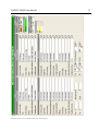
1
ASPECT 2000D User Manual
1
ASPECT 2000D USER MANUAL
Document # UMASPECT2000D.001 Rev. ASPECT2000D.001
Table of Contents
1
Introduction ................................................ 4
1.1 Extent of Delivery ...................................................... 4
1.2 Connectors................................................................. 5
1.3 Power.......................................................................... 7
1.4 Remote Control Software.......................................... 8
1.4.1 System Requirements ........................................ 8
1.4.2 Installation .......................................................... 8
1.5 Front Panel Control ................................................... 9
1.5.1 Functions ............................................................ 9
1.5.2 Key Properties .................................................... 9
1.5.3 Menu Properties ............................................... 11
1.6 Using the Remote Control Software ...................... 12
1.6.1 Device Registration on the PC.......................... 12
1.6.2 Device selection on the PC............................... 13
2
Housekeeping Functions ........................ 14
2.1 Introduction.............................................................. 14
2.1.1 Keyboard button lights ...................................... 14
2.1.2 Keyboard display contrast................................. 14
3
Video Input ............................................... 15
3.1 Input Source and Standard Selection .................... 15
3.1.1 Input Source ..................................................... 16
3.1.2 Automatic Input Standard Selection.................. 17
3.1.3 Manual Input Standard Selection...................... 18
3.2 Various Input Setup Features ................................. 19
3.2.1 Input Black/White.............................................. 19
3.3 Preset Input Source and Standard Selection ........ 20
3.3.1 Recalling a local input Preset............................ 20
3.3.2 Saving a local input Preset ............................... 21
4
Input Video Proc Amp ............................. 22
4.1 Input Proc Amp.........................................................22
4.1.1 Input Luminance Gain (Gain Y) .........................22
4.1.2 Input Chroma Gain (Gain C) .............................23
4.1.3 Input Chroma Balance Cb/Cr .............................24
4.1.4 Input Black Level (pedestal) ..............................25
4.1.5 Input Offset Cb ...................................................26
4.1.6 Input Offset Cr ...................................................27
4.1.7 Input horizontal Position ....................................28
4.1.8 Input horizontal Chroma Position ......................29
4.1.9 Input vertical Position ........................................30
4.1.10 Input vertical Chroma Position...........................31
4.2 Preset Proc Amp ......................................................32
4.2.1 Recalling a Proc Amp default Setup
(Predefinition) ....................................................32
4.2.2 Recalling a local Proc Amp Preset ....................33
4.2.3 Saving a local Proc Amp Preset ........................34
5
Video Output ............................................ 35
5.1 System Output Settings...........................................35
5.1.1 Output Standard Selection ................................36
5.1.2 Output Bypass...................................................36
5.1.3 Freeze ...............................................................37
5.1.4 Output DV Format .............................................38
5.2 Output Preset ...........................................................39
5.2.1 Recalling a local Output Preset .........................39
5.2.2 Saving a local Output Preset .............................40
6
System Synchronisation ......................... 41
6.1 Introduction ..............................................................41
6.2 Genlock Operation ...................................................42
6.2.1 Genlock Activate ...............................................42
6.2.2 Genlock H- Delay ..............................................43
6.2.3 Genlock Termination .........................................44
6.3 Genlock Preset .........................................................45
6.3.1 Recalling a local Genlock Preset.......................45
6.3.2 Saving a local Genlock Preset...........................46
7
Test Pattern .............................................. 47
7.1 Test Pattern ..............................................................47
7.1.1 Test Pattern activation.......................................47
7.1.2 Test Pattern Selection .......................................48
ModelASPECT2000D Document # UMASPECT2000D.001 Rev. ASPECT2000D.001
2
8
ASPECT 2000D User Manual
VBI- Processing........................................ 49
11 Video Signal Processing .........................84
8.1 VBI- Processing (Caption)....................................... 49
8.1.1 VBI Test Signal Insertion .................................. 50
8.1.2 Timecode inserter / manual VITC line select..... 51
11.1 General Functions ....................................................84
11.1.1 Filter enable.......................................................85
8.2 VBI Preset ................................................................. 52
8.2.1 Recalling a local VBI Preset.............................. 52
8.2.2 Saving a local VBI Preset ................................. 53
9 Aspect Ratio Conversion (ARC) and
Zoom ................................................................ 54
9.1 Introduction.............................................................. 54
9.1.1 ARC Input Control............................................. 54
9.1.2 Manual selection of the input format ................. 55
9.1.3 Selection of the output format ........................... 56
9.2 Zoom, Pan & Scan ................................................... 57
9.2.1 Manual adjustment of the output zoom factor ... 57
9.2.2 Manual adjustment of the output aspect ratio ... 58
9.2.3 Manual adjustment of the output horizontal
zoom ................................................................. 59
9.2.4 Manual adjustment of the output vertical zoom. 60
9.2.5 Manual adjustment of Pan ................................ 61
9.2.6 Manual adjustment of Scan............................... 62
9.3 Crop .......................................................................... 63
9.3.1 Input Cropping Top ........................................... 63
9.3.2 Input Cropping bottom ...................................... 64
9.3.3 Input Cropping right .......................................... 65
9.3.4 Input Cropping left............................................. 66
9.3.5 Output Cropping top.......................................... 67
9.3.6 Output Cropping bottom.................................... 68
9.3.7 Output Cropping right........................................ 69
9.3.8 Output Cropping left.......................................... 70
9.4 Aspect & Zoom Background color ......................... 71
9.4.1 Output background color zoom area ................. 71
9.4.2 Output background color crop area................... 72
9.5 Aspect & Zoom Preset............................................. 73
9.5.1 Recalling a Aspect & Zoom default Setup
(Predefinition).................................................... 73
9.5.2 Recalling a local Aspect & Zoom Preset ........... 74
9.5.3 Saving a local Aspect & Zoom Preset............... 75
10 WSS / VI (Wide Screen Signaling, Video
Indexing).......................................................... 76
11.2 Enhancement (Aperture Correction).......................86
11.2.1 Horizontal / Vertical Enhancement ....................87
11.2.2 Coring Enhancement.........................................88
11.3 Noise Reduction, Linear Filters...............................89
11.3.1 Recursive Noise Reduction Filter ......................89
11.4 Noise Reduction, Nonlinear Filter...........................91
11.4.1 Median Filter Factor A .......................................91
11.4.2 Median Filter Factor B .......................................92
11.5 Filter Preset...............................................................93
11.5.1 Recalling a Filter default Setup (Predefinition)...93
11.5.2 Recalling a local Filter Preset ............................94
11.5.3 Saving a local Filter Preset ................................95
Color Correction .............................................96
11.6 Introduction ..............................................................96
11.6.1 Color Correction Enable ....................................97
11.6.2 Color Correction pre white level.........................98
11.6.3 Color Correction pre black level.........................99
11.6.4 Color Correction gamma .................................100
11.6.5 Color Correction post white level .....................101
11.6.6 Color Correction post black level .....................102
11.6.7 Color Correction display ..................................103
11.7 Preset Color Correction .........................................104
11.7.1 Recalling a color correction default Setup
(Predefinition) ..................................................104
11.7.2 Recalling a local color correction Preset..........105
11.7.3 Saving a local color correction Preset .............106
12 Legalizer.................................................. 107
12.1 Introduction ............................................................107
12.1.1 Legalizer Enable.............................................107
12.1.2 Legalizer upper limit .......................................108
12.1.3 Legalizer lower limit ........................................109
12.2 Preset Legalizer ......................................................110
12.2.1 Recalling a Legalizer default Setup
(Predefinition) ..................................................110
12.2.2 Recalling a local legalizer Preset.....................111
12.2.3 Saving a local legalizer Preset.........................112
10.1 Introduction.............................................................. 76
10.1.1 Output WSS enable .......................................... 78
10.1.2 Output VI enable ............................................... 79
10.1.3 Output WSS / VI status OSD ............................ 80
10.2 WSS / VI Preset ........................................................ 81
10.2.1 Recalling a WSS / VI default Setup
(Predefinition).................................................... 81
10.2.2 Recalling a local WSS / VI Preset ..................... 82
10.2.3 Saving a local WSS / VI Preset......................... 83
ModelASPECT2000D Document # UMASPECT2000D.001 Rev. ASPECT2000D.001
ASPECT 2000D User Manual
3
13 Audio Processing .................................. 113
15 Timecode ................................................ 151
13.1 Introduction............................................................ 113
15.1 Introduction ............................................................151
13.2 Audio Input............................................................. 115
13.2.1 Input Mute....................................................... 115
13.2.2 Audio Input Master Level ................................ 116
13.2.3 Audio Input Gain & Level ................................ 117
13.2.4 Audio Input XLR select analog / AES ............. 118
13.2.5 DV Audio Resampling Input............................ 119
13.2.6 DV Audio Input channel select........................ 120
15.2 Timecode- Reader ..................................................152
15.2.1 Timecode Reader Source select .....................154
15.2.2 Timecode Reader VITC line select auto..........155
15.2.3 Timecode Reader manual VITC line select .....156
15.2.4 Keyboard setting of the reader dropframe
mode ...............................................................157
13.3 Preset Audio Input................................................. 121
13.3.1 Recalling a Audio Gain default Setup
(Predefinition) ................................................. 121
13.3.2 Recalling a Audio Level default Setup
(Predefinition) ................................................. 122
13.3.3 Recalling a local audio input processing Preset....
13.3.4 Saving a local audio input processing Preset . 124
13.4 Audio Delay ............................................................ 125
13.4.1 Audio Auto Delay ............................................ 125
13.4.2 Audio Master Delay ........................................ 126
13.4.3 Separate Audio channel Delay ....................... 127
13.5 Preset Audio Delay ................................................ 128
13.5.1 Recalling a Audio Delay default Setup
(Predefinition)............................................................. 128
13.5.2 Recalling a local audio delay Preset ............... 129
13.5.3 Saving a local audio delay Preset ................... 130
13.6 Audio Output.......................................................... 131
13.6.1 Operating the Audio Routing........................... 131
13.6.2 Audio Embedder Sequence ............................ 132
13.6.3 Audio Control Packet ...................................... 133
13.6.4 DV Audio Resampling Output ......................... 134
13.6.5 DV Audio Output channel select ..................... 135
13.7 Preset Audio Output.............................................. 136
13.7.1 Recalling an Audio SDI Output default Setup
(Predefinition) ................................................. 136
13.7.2 Recalling an Audio XLR Output (deembedding)
default Setup (Predefinition) ........................... 137
13.7.3 Recalling an Audio DV Output default Setup
(Predefinition) ................................................. 138
13.7.4 Recalling a local output Preset ....................... 139
13.7.5 Saving a local audio output Preset ................. 140
14 Cursors ................................................... 141
14.1 Introduction............................................................ 141
14.1.1 Cursor enable ................................................. 141
14.1.2 Cursor position display.................................... 142
14.1.3 Cursor position horizontal, left ........................ 143
14.1.4 Cursor position horizontal, right ...................... 144
14.1.5 Cursor position vertical, top ............................ 145
14.1.6 Cursor position vertical, bottom ...................... 146
14.1.7 Cursor Mode ................................................... 147
14.2 Cursor Preset ......................................................... 148
14.2.1 Recalling a Cursor default Setup (Predefinition)148
14.2.2 Recalling a local Cursor Preset....................... 149
14.2.3 Saving a local cursor Preset ........................... 150
ModelASPECT2000D Document # UMASPECT2000D.001 Rev. ASPECT2000D.001
15.3 Timecode- Inserter .................................................158
15.3.1 Timecode inserter MASTER activate ..............158
15.3.2 Timecode inserter VITC activate .....................159
15.3.3 Timecode inserter manual VITC line select.....160
15.3.4 Timecode inserter RP196 activate ..................161
15.3.5 Timecode inserter manual RP196 line select ..162
123 15.3.6 Timecode inserter RP188 activate ..................163
15.3.7 Timecode inserter manual RP188 line select ..164
15.3.8 Timecode inserter DV-TC activate ..................165
15.3.9 Timecode inserter LTC format.........................166
15.4 Timecode Generator ..............................................167
15.4.1 Introduction .....................................................167
15.4.2 Normal- and Expertmode ................................168
15.4.3 Keyboard setting of the generator mode .........170
15.4.4 Keyboard setting of the generator start value..171
15.4.5 Keyboard setting of the generator dropframe
mode ...............................................................172
15.5 Timecode Display...................................................173
15.5.1 Introduction .....................................................173
15.5.2 Timecode Display Enable................................173
15.5.3 Timecode reader horizontal display position ...174
15.5.4 Timecode reader vertical display position........175
15.5.5 Timecode generator horizontal display position176
15.5.6 Timecode generator vertical display position...177
15.6 Timecode Preset.....................................................178
15.6.1 Recalling a local timecode Preset ...................178
15.6.2 Saving a local timecode Preset .......................179
16 Presets .................................................... 180
16.1 Introduction ............................................................180
16.2 Preset Operation ....................................................181
16.2.1 Storing of a global Preset ................................181
16.2.2 Recalling of a global Preset.............................182
16.2.3 Assigning a name to a global Preset ...............183
16.3 Backup and Restore of Presets on the remote PC184
17 Maintenance ........................................... 185
17.1 Introduction ............................................................185
17.1.1 Version Display ...............................................185
17.1.2 Status Display .................................................186
4
ASPECT 2000D User Manual
1 Introduction
Dear user,
You have an ASPECT 2000D. This machine gives you a broad variety of functionality. Here is a short
overview:
•
•
•
•
•
•
•
•
•
•
•
1.1
Video Proc Amp
Frame store synchronizer
Aspect ratio controller including WSS and VI
Enhancement
Noise Reduction with linear and median filters
Legalizing / Gamma correction (optional)
Caption / VBI Processing
DV / Firewire I/O
Timecode Generation / Regeneration
Audio Embedding / Deembedding (optional)
Audio Routing, Delay and Level Control
Extent of Delivery
The system comes with
•
•
CD including this documentation and the Remote Control Control Software (occasionally optional)
Power Chord
Please check for completeness. If items are missing, please contact your dealer.
ModelASPECT2000D Document # UMASPECT2000D.001 Rev. ASPECT2000D.001
ASPECT 2000D User Manual
1.2
5
Connectors
This rear panel view shows the connectivity of the system. Optional connectors are shown with grey
background.
Genlock Inputs
LTC- Input
SDI Input
Digital Audio Inputs
CVBS- Inputs
Analog Audio Inputs
Power
Analog Audio Outputs
Digital Audio Outputs
LTC- Output
DV / Firewire
I/O
SDI Output
RS-232- Port for
Remote Control
Power
The power connector conforms to IEC 60320-1/C14.
The unit accepts 100 – 260VAC with either 50Hz or 60Hz.
Analogue Audio Inputs*
The unit supports 4 independant analog audio channels. The first
channel is located leftside besides the power connector (rear view).
The audio connectors use mini XLR plugs. Standard input levels are
calibrated to 0dBu = -15dBfs.
Connector assignment :
Input 1 = Audio 1, left channel
Input 2 = Audio 1, right channel
Input 3 = Audio 2, left channel
Input 4 = Audio 2, right channel
ModelASPECT2000D Document # UMASPECT2000D.001 Rev. ASPECT2000D.001
6
ASPECT 2000D User Manual
Digital Audio Inputs*
Two input connectors for AES/EBU or S/PDIF signals are provided
The first input is located left (rear view) besides the analog audio
The connectors are of BNC type.
LTC- Input *
This input is dedicated to connect LTC timecode sources as Betacam,or external timecodegenerators It supports levels conforming to
SMPTE und EBU.
The connector is of BNC type.
DV- Input / Output
Supports miniDV-, DV-, DVCAM- or DVCpro - sources.
A 6-pin IEEE1394- or Firewire- connector is used.
Bidirectional
SDI- Input
SDI input conforming to SMPTE.259M / 272 M
The connectors are of BNC type.
Analogue Genlock Inputs
Accepts Blackburst- or Composite- Video.
The connectors are of BNC type.
RS232 Port for Remote Control used to connect the system with an external PC or Network Interface.
Sub-D 9-pin female plug.
Analogue Audio Outputs*
The unit supports 4 independant analog audio channels. The first
channel is located leftside besides the power connector (rear view).
The audio connectors use mini XLR plugs. Standard output levels
are calibrated to 0dBu = -15dBfs.
Connector assignment :
Input 1 = Audio 1, left channel
Input 2 = Audio 1, right channel
Input 3 = Audio 2, left channel
Input 4 = Audio 2, right channel
Digital Audio Outputs*
Two output connectors for AES/EBU or S/PDIF signals are provided
The first output is located left (rear view) besides the analog audio.
The connectors are of BNC type.
LTC- Output *
This output is dedicated to connect LTC timecode destinations as
Betacam. It supports levels conforming to SMPTE und EBU.
The connector is of BNC type.
SDI- Output
SDI output conforming to SMPTE.259M / 272 M
BNC connector
.
* optional
ModelASPECT2000D Document # UMASPECT2000D.001 Rev. ASPECT2000D.001
ASPECT 2000D User Manual
1.3
7
Power
Rear Panel
Main Power Plug
Figure 1.3-1
Right Front Panel with Power
Switch
Figure 1.3-2
1. Connect the power cable to the unit
2. Press the Power switch to turn the unit ON. All control lights will illuminate until the system ends its
boot procedure. During this, the following message appears on the display :
booting system
please wait...
If no button lights up after the start period check the LED Bright seting in the panel menu. The adjustment must be greater than zero in order to illuminate the lights
ModelASPECT2000D Document # UMASPECT2000D.001 Rev. ASPECT2000D.001
8
1.4
ASPECT 2000D User Manual
Remote Control Software
The ASPECT 2000D package may contain software to control the unit via a PC.
Using the software has some essential advantages versus operating the unit via the local control panel
1. the complete range of functions is supported
2. in many situations, the software does it far more clearly and self explaining.
If it is necessary to connect the systems to a network, special RS232- to Ethernet- Converters are provided as an option.
1.4.1
System Requirements
To use the software, the PC should fulfill the following requirements
•
•
•
•
•
Prozessor speed greater than 1GHz
512MB Ram
Microsoft Windows 2000, XP, 2003, Vista
At least 10MB disc capacity
Screen resolution 1024 x 768 or better, 65.535 colours or better
1.4.2 Installation
To install the Remote Control Software please proceed as follows:
•
•
•
•
•
•
•
•
•
•
Insert the CD into your CD-/DVD- drive. In most cases, an explorer window will appear which
shows the content of the CD. If this should not be the case, please select and open the CD manually.
Select the folder „Software” and click on „setup.exe“.
Please wait until the installation program has been started.
Click on „proceed“.
Select the folder for the installation or accept the proposed folder and click on „proceed“.
Select the name for the start menu or accept the proposal and click on „proceed“..
Now the installation software shows the current setup. Please confirm with „proceed“..
The software will be installed. Please wait until the process is completed.
Click on „proceed” to finish and exit the installation program.
The software now is installed and can be started.
ModelASPECT2000D Document # UMASPECT2000D.001 Rev. ASPECT2000D.001
ASPECT 2000D User Manual
1.5
9
Front Panel Control
1.5.1
Functions
Most of the functions of the system can be controlled via the local keyboard.
There are some exceptions:
•
•
•
•
•
Audio routing
Separate Audiogain and -level
Separate Audio delay
VBI- Setup
Special Timecode properties
For these functions, special setup configurations ar recalled which can be defined using the remote
control software.
1.5.2
Key Properties
There are three groups of keys with different properties.
•
•
•
Toggle key (directly modifies the parameter of a function)
Shortcut key (provides fast access of a dedicated function bypassing the menu structure)
Submenu key (provides fast access of a submenu)
Toggle keys
DV
SDI
Black (also acts as shortcut key for testpattern menu)
Bars (also acts as shortcut key for testpattern menu)
Bars
Freeze
Disable
Audio Mute
Monitor Mute
Bypass
When pressed, these keys directly change the status of the related function.
The red LED inside the key indicates whether the related function is active or not.
The keys which cover the source selection have a special behaviour. Pressing one of these keys selects the desired input and activates the related context menu.
Flashing of the LED further indicates loss of signal on the input Reason could be either loss of signal,
a wrong input standard etc. If this occurs, please also check the status of the automatic standard selection.
ModelASPECT2000D Document # UMASPECT2000D.001 Rev. ASPECT2000D.001
10
ASPECT 2000D User Manual
Shortcut keys
(STD) Standard
Blacklevel
V Gain
C Gain
C Bal
Audio level
Monitor level
These keys point directly to a menu function and allow parameter modification via the rotary knob.
The red LED of the key is used to signal two different events.
• Flashing indicates that the parameter can be modified via the rotary knob.
• Steady light indicates that the parameter is modified to nonstandard. In this case, normally the
function modifies the related signal.
Pressing the key for about 2 seconds will set the parameter value back to default.
Submenu keys
Recursive
Median
Aspect
Zoom
Crop
Timing
Audio Delay
Monitor select
Monitor Level
Genlock
Preset
These keys point to the related submenu. It normally contains more than one function, which can be
operated via the keys Menu and Select and the rotary knob.
The red LED of these keys is used to indicate the following:
•
•
Flashing indicates that the related menu is activated.
Steady light indicates that one of the related functions has a nondefault parameter In this case,
normally the function modifies the related signal.
Pressing the key for about 2 seconds will set all parameter values of the related menu back to default.
ModelASPECT2000D Document # UMASPECT2000D.001 Rev. ASPECT2000D.001
ASPECT 2000D User Manual
11
1.5.3 Menu Properties
The main menu is operated via the keys Menu and Select and the rotary knob.
The key Menu activates / deactivates the selected menu. The system stores the last active position and
recalls it when entering the menu again.
If you wish to go to the menu start, please deactivate the menu and activate it again.
All menus are operated similar. The cursor is moved by the rotary knob while the key Select recalls the
menu item.
If the cursor is on ↑, the key Select leads to the next level in the menu tree.
If the cursor points to a parameter, it can be modified via the rotary knob. To leave this status, please
press Select.
ModelASPECT2000D Document # UMASPECT2000D.001 Rev. ASPECT2000D.001
12
ASPECT 2000D User Manual
1.6
Using the Remote Control Software
The Remote Control Software supports all the functions of the system. It allows a very intuitive and well
arranged presentation of the functions in use.
1-1
1-2
1.6.1
Device Registration on the PC
To connect the PC to a system, there are two possibilities:
•
Scanning all the serial interfaces available on the PC
In the main menu (1-1), please click „Devices“ and afterwards „scan“. Now the software checks all
available serial interfaces on the presence of a system. The procedure can be observed looking at
the device list.
If only one system is detected, the software automatically connects.
•
Adding an interface manually
In the main menu (1-1), please click „Devices“ and afterwards „Add“. The window „Add Port…“ (12) appears. Please select the desired serial interface, set it to 38.400baud and click „Add“. Now
the software checks the selected port, reads out the type of system and its name and connects.
ModelASPECT2000D Document # UMASPECT2000D.001 Rev. ASPECT2000D.001
ASPECT 2000D User Manual
1.6.2
13
Device selection on the PC
The software is capable to administer more than one device. All windows and their positions are stored
independently for the different instances.
To select a specific system, please use the main menu (1-1) and click on „Devices“. Out of the list, select the desired system and click on „Select“.
Alternatively, you can double click on the selected list entry. Then the software connects to the system
and recalls all the windows and their positions as they were specified at the last session.
ModelASPECT2000D Document # UMASPECT2000D.001 Rev. ASPECT2000D.001
14
ASPECT 2000D User Manual
2 Housekeeping Functions
2.1
Introduction
This chapter describes some basic setup functions.
2.1.1
Keyboard button lights
Controls the intensity of the button lights
Via Menu
1.
2.
3.
4.
5.
6.
Press Menu
Turn the rotary knob until the cursor points to Panel
Press Select
Turn the rotary knob until the cursor points to LED BRIGHT
Press Select
Turn the rotary knob to adjust the intensity
Via Shortcut
n/a
Via Remote Control Software
n/a
2.1.2
Keyboard display contrast
Controls the contrast of the alphanumeric readout.
Via Menu
1.
2.
3.
4.
5.
6.
Press Menu
Turn the rotary knob until the cursor points to Panel
Press Select
Turn the rotary knob until the cursor points to Contrast
Press Select
Turn the rotary knob to adjust the contrast
Via Shortcut
n/a
Via Remote Control Software
n/a
ModelASPECT2000D Document # UMASPECT2000D.001 Rev. ASPECT2000D.001
ASPECT 2000D User Manual
3 Video Input
3.1
Input Source and Standard Selection
ModelASPECT2000D Document # UMASPECT2000D.001 Rev. ASPECT2000D.001
15
16
ASPECT 2000D User Manual
3.1.1
Input Source
The ASPECT 2000D supports the following input sources :
a) DV / Firewire (IEEE1394). There is one connector available for both input and output.
If the DV source is not selected, it automatically acts as an output.
The DV interface supports DVCAM and DVCPro.
b) Digital components conforming to SMPTE 259M / 272M
Via Menu
1.
2.
3.
4.
5.
6.
Press Menu
Turn the rotary knob until the cursor points to Input
Press Select
Turn the rotary knob until the cursor points to Source
Press Select
select the desired source
Via Shortcut
1. Press the corresponding key in the input field.
2. The desired input will be selected immediately
Via Remote Control Software
1. Open the window Input
2. select the desired input
3. The desired input will be selected immediately
ModelASPECT2000D Document # UMASPECT2000D.001 Rev. ASPECT2000D.001
ASPECT 2000D User Manual
3.1.2
17
Automatic Input Standard Selection
The system is able to detect the supported standards automatically. This feature can be switched off if
desired.
Please note
The vertical frequency of the output signal will always follow the conditions on the input.
Via Menu
1.
2.
3.
4.
5.
6.
Press Menu
Turn the rotary knob until the cursor points to Input
Press Select
Turn the rotary knob until the cursor points to Autosel
Press Select
Select ON / OFF
Via Shortcut
1.
2.
3.
4.
Press the corresponding key in the input field
the menu will show Autosel
Press Select
Select ON / OFF
Via Remote Control Software
1. Open the window Input
2. select the desired status in the field Autoselect
ModelASPECT2000D Document # UMASPECT2000D.001 Rev. ASPECT2000D.001
18
ASPECT 2000D User Manual
3.1.3
Manual Input Standard Selection
Normally, one would use the automatic standard selection.
But under special circumstances (e.g. instable input signal), it can be usefull to set the input
standard manually.
It is not possible to select the standard manually as long as the automatic is ON.
The vertical frequency of the output signal will follow the input.
Via Menu
1.
2.
3.
4.
5.
6.
Press Menu
Turn the rotary knob until the cursor points to Input
Press Select
Turn the rotary knob until the cursor points to Standard
Press Select
Select the desired standard. If it is not possible to select a standard manually, please check
whether automatic selection is enabled.
7. The system may need up to 1sec to detect the incoming standard.
Via Shortcut
1. Press the key STD in the input field.
2. Select the desired standard. If it is not possible to select a standard manually, please check
whether automatic selection is enabled.
3. The system may need up to 1sec to detect the incoming standard.
Via Remote Control Software
1. Open the window Input
2. select the desired standard
ModelASPECT2000D Document # UMASPECT2000D.001 Rev. ASPECT2000D.001
ASPECT 2000D User Manual
3.2
Various Input Setup Features
Some inputs accasionally net additional setup.
This chapter contains the supported features.
3.2.1
Input Black/White
Disables input colour information.
Via Menu
1.
2.
3.
4.
5.
6.
Press Menu
Turn the rotary knob until the cursor points to Input
Press Select
Turn the rotary knob until the cursor points to B/W
Press Select
Select color or B/W
Via Shortcut
n/a
Via Remote Control Software
1. Open the window Input
2. click B/W or Color in the option field. The B/W status will be marked red as a warning
ModelASPECT2000D Document # UMASPECT2000D.001 Rev. ASPECT2000D.001
19
20
3.3
ASPECT 2000D User Manual
Preset Input Source and Standard Selection
3.3.1 Recalling a local input Preset
work
: current status
user 1 .. 4 : user defined local preset
global
: user defined global preset
Via Menu
1.
2.
3.
4.
5.
6.
Press Menu
Turn the rotary knob until the cursor points to Input
Press Select
Turn the rotary knob until the cursor points to Preset
Press Select
select the desired setting via the rotary knob
Via Shortcut
n/a
Via Remote Control Software
1. Open the window Input
2. change setting in the Preset field as desired
ModelASPECT2000D Document # UMASPECT2000D.001 Rev. ASPECT2000D.001
ASPECT 2000D User Manual
3.3.2 Saving a local input Preset
Up to 4 local prest configurations can be stored as user 1 .. user 4
Via Menu
1.
2.
3.
4.
5.
6.
7.
Press Menu
Turn the rotary knob until the cursor points to Input
Press Select
Turn the rotary knob until the cursor points to Save Preset
Press Select
select the desired Preset via the rotary knob
Press Select
Via Shortcut
n/a
Via Remote Control Software
1. Open the window Input
2. select the desired Preset
ModelASPECT2000D Document # UMASPECT2000D.001 Rev. ASPECT2000D.001
21
22
ASPECT 2000D User Manual
4 Input Video Proc Amp
4.1
Input Proc Amp
Video signals undergo various types of distortion. The level of luminance and / or chrominance may
change, decoders sometimes produce incorrect timing etc.
For this reason, the system provides a versatile input Proc Amp to correct various signal parameters.
4.1.1
Input Luminance Gain (Gain Y)
Adjustment of the luminance input gain.
Range 0.000 … 1.999.
Available for all sources.
Via Menu
1.
2.
3.
4.
5.
6.
Press Menu
Turn the rotary knob until the cursor points to Procamp
Press Select
Turn the rotary knob until the cursor points to Gain Y
Press Select
Adjust by turning the rotary knob
Via Shortcut
1. Press Y Gain
2. Adjust by turning the rotary knob
Via Remote Control Software
1. Open the window Proc Amp
2. adjust Gain Y to the desired level
ModelASPECT2000D Document # UMASPECT2000D.001 Rev. ASPECT2000D.001
ASPECT 2000D User Manual
4.1.2
Input Chroma Gain (Gain C)
Adjustment of the chrominance input gain. Controls both Cb- and Cr- components simultaniously
Range 0.000 … 1.999.
Available for all sources.
.
Via Menu
1.
2.
3.
4.
5.
6.
Press Menu
Turn the rotary knob until the cursor points to Procamp
Press Select
Turn the rotary knob until the cursor points to Gain C
Press Select
Adjust by turning the rotary knob
Via Shortcut
1. Press C Gain
2. Adjust by turning the rotary knob
Via Remote Control Software
1. Open the window Proc Amp
2. adjust Gain C to the desired level
ModelASPECT2000D Document # UMASPECT2000D.001 Rev. ASPECT2000D.001
23
24
ASPECT 2000D User Manual
4.1.3
Input Chroma Balance Cb/Cr
Adjustment of the Cb/Cr balance. Controls both Cb- and Cr- components simultaniously
Range 0.000 … 1.999.
Available for all sources.
Via Menu
1.
2.
3.
4.
5.
6.
Press Menu
Turn the rotary knob until the cursor points to Procamp
Press Select
Turn the rotary knob until the cursor points to Cb Cr Bal
Press Select
Adjust by turning the rotary knob
Via Shortcut
1. Press C Bal
2. Adjust by turning the rotary knob
Via Remote Control Software
1. Open the window Proc Amp
2. adjust Bal Cb / Cr to the desired ratio
ModelASPECT2000D Document # UMASPECT2000D.001 Rev. ASPECT2000D.001
ASPECT 2000D User Manual
4.1.4
25
Input Black Level (pedestal)
Video-black is defined in NTSC and Pal-M 7.5% above the blanking level. In PAL, PAL-N and SECAM it
is 0%. This setup is only available for NTSC, NTSC 4.43 and PAL-M
Adjustment of the input black level.
Range - 11,4% .. +11,4% in steps of 1‰
Available for all sources.
Via Menu
1.
2.
3.
4.
5.
6.
Press Menu
Turn the rotary knob until the cursor points to Procamp
Press Select
Turn the rotary knob until the cursor points to Bk Level
Press Select
Adjust by turning the rotary knob
Via Shortcut
1. Press Black Level
2. Adjust by turning the rotary knob
Via Remote Control Software
1. Open the window Proc Amp
2. adjust Bk Level to the desired value
ModelASPECT2000D Document # UMASPECT2000D.001 Rev. ASPECT2000D.001
26
ASPECT 2000D User Manual
4.1.5
Input Offset Cb
Adjustment of the input chrominance offset Cb
Range - 11,4% .. +11,4% in steps of 1‰
Available for all sources.
Via Menu
1.
2.
3.
4.
5.
6.
Press Menu
Turn the rotary knob until the cursor points to Procamp
Press Select
Turn the rotary knob until the cursor points to Offset Cb
Press Select
Adjust by turning the rotary knob
Via Shortcut
n/a
Via Remote Control Software
1. Open the window Proc Amp
2. adjust Offset Cb to the desired value
ModelASPECT2000D Document # UMASPECT2000D.001 Rev. ASPECT2000D.001
ASPECT 2000D User Manual
4.1.6 Input Offset Cr
Adjustment of the input chrominance offset Cb
Range - 11,4% .. +11,4% in steps of 1‰
Available for all sources.
Via Menu
1.
2.
3.
4.
5.
6.
Press Menu
Turn the rotary knob until the cursor points to Procamp
Press Select
Turn the rotary knob until the cursor points to Offset Cr
Press Select
Adjust by turning the rotary knob
Via Shortcut
n/a
Via Remote Control Software
1. Open the window Proc Amp
2. adjust Offset Cr to the desired value
ModelASPECT2000D Document # UMASPECT2000D.001 Rev. ASPECT2000D.001
27
28
ASPECT 2000D User Manual
4.1.7
Input horizontal Position
Adjustment of the horizontal input timing, luminance / chrominance.
Range -2370ns .. +2296ns in steps of 74ns (1 luminance pixel)
Via Menu
1.
2.
3.
4.
5.
6.
7.
8.
9.
10.
Press Menu
Turn the rotary knob until the cursor points to Procamp
Press Select
Turn the rotary knob until the cursor points to Timing
Press Select
Turn the rotary knob until the cursor points to Y+C
Press Select
Turn the rotary knob until the cursor points to Pos H
Press Select
Adjust by turning the rotary knob
Via Shortcut
1.
2.
3.
4.
5.
6.
Press Timing
Turn the rotary knob until the cursor points to Y+C
Press Select
Turn the rotary knob until the cursor points to Pos H
Press Select
Adjust by turning the rotary knob
Via Remote Control Software
1. Open the window Proc Amp
2. adjust Pos H to the desired position
ModelASPECT2000D Document # UMASPECT2000D.001 Rev. ASPECT2000D.001
ASPECT 2000D User Manual
4.1.8
Input horizontal Chroma Position
Adjustment of the horizontal input chroinance timing.
Range -2370ns .. +2296ns in steps of 74ns (1 luminance pixel)
Via Menu
1.
2.
3.
4.
5.
6.
7.
8.
9.
10.
Press Menu
Turn the rotary knob until the cursor points to Procamp
Press Select
Turn the rotary knob until the cursor points to Timing
Press Select
Turn the rotary knob until the cursor points to C to Y
Press Select
Turn the rotary knob until the cursor points to C Pos H
Press Select
Adjust by turning the rotary knob
Via Shortcut
1.
2.
3.
4.
5.
6.
Press Timing
Turn the rotary knob until the cursor points to C to Y
Press Select
Turn the rotary knob until the cursor points to C Pos H
Press Select
Adjust by turning the rotary knob
Via Remote Control Software
1. Open the window Proc Amp
2. adjust Ch Pos H to the desired position
ModelASPECT2000D Document # UMASPECT2000D.001 Rev. ASPECT2000D.001
29
30
ASPECT 2000D User Manual
4.1.9
Input vertical Position
Adjustment of the vertical input timing, luminance / chrominance.
Range -8lines .. +7 lines in steps of 1line
Via Menu
1.
2.
3.
4.
5.
6.
7.
8.
9.
10.
Press Menu
Turn the rotary knob until the cursor points to Procamp
Press Select
Turn the rotary knob until the cursor points to Timing
Press Select
Turn the rotary knob until the cursor points to Y+C
Press Select
Turn the rotary knob until the cursor points to Pos V
Press Select
Adjust by turning the rotary knob
Via Shortcut
1.
2.
3.
4.
5.
6.
Press Timing
Turn the rotary knob until the cursor points to Y+C
Press Select
Turn the rotary knob until the cursor points to Pos V
Press Select
Adjust by turning the rotary knob
Via Remote Control Software
1. Open the window Proc Amp
2. adjust Pos V to the desired position
ModelASPECT2000D Document # UMASPECT2000D.001 Rev. ASPECT2000D.001
ASPECT 2000D User Manual
4.1.10
Input vertical Chroma Position
Adjustment of the vertical input chroinance timing.
Range -8lines .. +7 lines in steps of 1line
Via Menu
1.
2.
3.
4.
5.
6.
7.
8.
9.
10.
Press Menu
Turn the rotary knob until the cursor points to Procamp
Press Select
Turn the rotary knob until the cursor points to Timing
Press Select
Turn the rotary knob until the cursor points to C to Y
Press Select
Turn the rotary knob until the cursor points to C Pos V
Press Select
Adjust by turning the rotary knob
Via Shortcut
1.
2.
3.
4.
5.
6.
Press Timing
Turn the rotary knob until the cursor points to C to Y
Press Select
Turn the rotary knob until the cursor points to C Pos V
Press Select
Adjust by turning the rotary knob
Via Remote Control Software
1. Open the window Proc Amp
2. adjust Ch Pos V to the desired position
ModelASPECT2000D Document # UMASPECT2000D.001 Rev. ASPECT2000D.001
31
32
4.2
ASPECT 2000D User Manual
Preset Proc Amp
4.2.1
Recalling a Proc Amp default Setup (Predefinition)
The default Setup provides a common reset to the Proc Amp functions.
Via Menu
1.
2.
3.
4.
5.
6.
Press Menu
Turn the rotary knob until the cursor points to Procamp
Press Select
Turn the rotary knob until the cursor points to Predef
Press Select
Select default by turning the rotary knob
Via Shortcut
n/a
Via Remote Control Software
1. Open the window Proc Amp
2. Select default in the PRE-Definition field
ModelASPECT2000D Document # UMASPECT2000D.001 Rev. ASPECT2000D.001
ASPECT 2000D User Manual
4.2.2 Recalling a local Proc Amp Preset
work
: current status
user 1 .. 4 : user defined local preset
global
: user defined global preset
Via Menu
1.
2.
3.
4.
5.
6.
Press Menu
Turn the rotary knob until the cursor points to Procamp
Press Select
Turn the rotary knob until the cursor points to Preset
Press Select
select the desired setting via the rotary knob
Via Shortcut
n/a
Via Remote Control Software
1. Open the window Proc Amp
2. change setting in the Preset field as desired
ModelASPECT2000D Document # UMASPECT2000D.001 Rev. ASPECT2000D.001
33
34
ASPECT 2000D User Manual
4.2.3 Saving a local Proc Amp Preset
Up to 4 local preset configurations can be stored as user 1 .. user 4
Via Menu
1.
2.
3.
4.
5.
6.
7.
Press Menu
Turn the rotary knob until the cursor points to Procamp
Press Select
Turn the rotary knob until the cursor points to Save Preset
Press Select
select the desired Preset via the rotary knob
Press Select
Via Shortcut
n/a
Via Remote Control Software
1. Open the window Proc Amp
2. select the desired Preset
ModelASPECT2000D Document # UMASPECT2000D.001 Rev. ASPECT2000D.001
ASPECT 2000D User Manual
5 Video Output
5.1
System Output Settings
ModelASPECT2000D Document # UMASPECT2000D.001 Rev. ASPECT2000D.001
35
36
ASPECT 2000D User Manual
5.1.1
Output Standard Selection
The vertical frequency of the output follows the signal on the input of the system. That means, it is not
possible to directly select a desired output standard. Select an appropriate input standard instead.
5.1.2
Output Bypass
By selecting bypass to „ON“, the inputs of the system are directly bypassed to the corresponding outputs.
This function is not supported by the SDI I/O and the Firewire I/O
Via Menu
1.
2.
3.
4.
5.
6.
Press Menu
Turn the rotary knob until the cursor points to Output
Press Select
Turn the rotary knob until the cursor points to Bypass
Press Select
select Bypass ON or OFF
Via Shortcut
1. Press Bypass
2. the key acts as a toggle key. Pressing bypass again switches back to the system output
Via Remote Control Software
1. Open the window Output
2. select Bypass ON or OFF
ModelASPECT2000D Document # UMASPECT2000D.001 Rev. ASPECT2000D.001
ASPECT 2000D User Manual
5.1.3
Freeze
Stores one frame and reads it out repeatedly
Via Menu
1.
2.
3.
4.
5.
6.
Press Menu
Turn the rotary knob until the cursor points to Output
Press Select
Turn the rotary knob until the cursor points to Freeze
Press Select
selcect ON or OFF
Via Shortcut
1. Press the key Freeze in the picture field. The function will toggle between ON and OFF
Via Remote Control Software
1. Open the window Mode
2. select Run or Freeze
ModelASPECT2000D Document # UMASPECT2000D.001 Rev. ASPECT2000D.001
37
38
5.1.4
ASPECT 2000D User Manual
Output DV Format
The system supports two DV formats.
DVCAM -> Colourcoding 4:2:0 (DVCAM, miniDV, DV)
DVCPRO -> Colourcoding 4:1:1 (DVCPro)
.
Via Menu
1.
2.
3.
4.
5.
6.
Press Menu
Turn the rotary knob until the cursor points to Output
Press Select
Turn the rotary knob until the cursor points to DV FORMAT
Press Select
Select DVCAM or DVCPRO
Via Shortcut
n/a
Via Remote Control Software
1. Open the window Output
2. Select DVCAM or DVCPRO
ModelASPECT2000D Document # UMASPECT2000D.001 Rev. ASPECT2000D.001
ASPECT 2000D User Manual
5.2
Output Preset
5.2.1 Recalling a local Output Preset
work
: current status
user 1 .. 4 : user defined local preset
global
: user defined global preset
Via Menu
1.
2.
3.
4.
5.
6.
Press Menu
Turn the rotary knob until the cursor points to Output
Press Select
Turn the rotary knob until the cursor points to Preset
Press Select
select the desired setting via the rotary knob
Via Shortcut
n/a
Via Remote Control Software
1. Open the window Output
2. change setting in the Preset field as desired
ModelASPECT2000D Document # UMASPECT2000D.001 Rev. ASPECT2000D.001
39
40
ASPECT 2000D User Manual
5.2.2 Saving a local Output Preset
Up to 4 local preset configurations can be stored as user 1 .. user 4
Via Menu
1.
2.
3.
4.
5.
6.
7.
Press Menu
Turn the rotary knob until the cursor points to Output
Press Select
Turn the rotary knob until the cursor points to Save Preset
Press Select
select the desired Preset via the rotary knob
Press Select
Via Shortcut
n/a
Via Remote Control Software
1. Open the window Output
2. select the desired Preset
ModelASPECT2000D Document # UMASPECT2000D.001 Rev. ASPECT2000D.001
ASPECT 2000D User Manual
41
6 System Synchronisation
6.1
Introduction
When various video sources are combined, their signals should be timed together,. A precision reference signal from a master sync-generator must be applied to each device and genlocked so that the
output of the equipment is synchronized with the timing of the reference. By connecting the individual
equipment to the timing reference source the processing delay of the equipment and the transmission
delay of the cable connecting the equipment must be taken into account. Individual timing adjustment
must be made to compensate for the different delays. For horizontal timing adjustment, use the H-POS
option, for the subcarrier-to-horizontal phase (Fsc/H) the FSC/H optionIn an production environment it is
common practice to operate all systems from a common sync source.
The black burst signal is often used for genlock equipment. It is a composite signal without active video,
but has all synchronization signals. The ASPECT 2000D also accepts a composite video signal as reference.
ModelASPECT2000D Document # UMASPECT2000D.001 Rev. ASPECT2000D.001
42
6.2
ASPECT 2000D User Manual
Genlock Operation
6.2.1
Genlock Activate
Activates / deactivates the Genlock Function.
Via Menu
1.
2.
3.
4.
Press Menu
Turn the rotary knob until the cursor points to Genlock
Press Select
Turn the rotary knob to activate / deactivate Genlock
Via Shortcut
1. Press the Genlock key in the rightmost field.
2. Press Select
3. Turn the rotary knob to activate / deactivate Genlock
Via Remote Control Software
1. Open the window Genlock
2. click On / Off ( Nodet )
off
lock
lock°
nolock
The system is synchronized internally from the input signal.
This message appears if the genlock mode is on and the external synchronization signal is recognized and the system is locked.
H-lock without FSC lock.
This message appears if the genlock mode is on, but is not locked to the external
source.
ModelASPECT2000D Document # UMASPECT2000D.001 Rev. ASPECT2000D.001
ASPECT 2000D User Manual
6.2.2
43
Genlock H- Delay
Defines the horizontal delay between reference- and output signal
Range : -16,0usec .. +15,96usec in steps of 37ns
The display shows n/a if no valid input signal is available
Via Menu
1.
2.
3.
4.
5.
6.
Press Menu
Turn the rotary knob until the cursor points to Genlock
Press Select
Turn the rotary knob until the cursor points to H- Pos
Press Select
select the desired value via the rotary knob
Via Shortcut
1.
2.
3.
4.
Press the Genlock key in the rightmost field.
Turn the rotary knob until the cursor points to H- Pos
Press Select
Turn the rotary knob to adjust to the desired value
Via Remote Control Software
1. Open the window Genlock
2. change H-Delay as desired
Genlock Signal
Output Signal
ModelASPECT2000D Document # UMASPECT2000D.001 Rev. ASPECT2000D.001
44
ASPECT 2000D User Manual
6.2.3 Genlock Termination
75 Ohm
Hi-Z
: Genlock Input terminated
: Genlock Input not terminated
Via Menu
1.
2.
3.
4.
5.
6.
Press Menu
Turn the rotary knob until the cursor points to Genlock
Press Select
Turn the rotary knob until the cursor points to Term
Press Select
select the desired setting via the rotary knob
Via Shortcut
1.
2.
3.
4.
Press the Genlock key in the rightmost field.
Turn the rotary knob until the cursor points to Term
Press Select
Turn the rotary knob to selct the desired status
Via Remote Control Software
1. Open the window Genlock
2. change setting as desired
ModelASPECT2000D Document # UMASPECT2000D.001 Rev. ASPECT2000D.001
ASPECT 2000D User Manual
6.3
Genlock Preset
6.3.1 Recalling a local Genlock Preset
work
: current status
user 1 .. 4 : user defined local preset
global
: user defined global preset
Via Menu
1.
2.
3.
4.
5.
6.
Press Menu
Turn the rotary knob until the cursor points to Genlock
Press Select
Turn the rotary knob until the cursor points to Preset
Press Select
select the desired setting via the rotary knob
Via Shortcut
1.
2.
3.
4.
Press the Genlock key in the rightmost field.
Turn the rotary knob until the cursor points to Preset
Press Select
select the desired setting via the rotary knob
Via Remote Control Software
1. Open the window Genlock
2. change setting in the Preset field as desired
ModelASPECT2000D Document # UMASPECT2000D.001 Rev. ASPECT2000D.001
45
46
ASPECT 2000D User Manual
6.3.2 Saving a local Genlock Preset
Up to 4 local prest configurations can be stored as user 1 .. user 4
Via Menu
1.
2.
3.
4.
5.
6.
7.
Press Menu
Turn the rotary knob until the cursor points to Genlock
Press Select
Turn the rotary knob until the cursor points to Save Preset
Press Select
select the desired Preset via the rotary knob
Press Select
Via Shortcut
1.
2.
3.
4.
Press the Genlock key in the rightmost field.
Turn the rotary knob until the cursor points to Save Preset
Press Select
select the desired Preset via the rotary knob
Via Remote Control Software
2. Open the window Genlock
3. select the desired Preset
ModelASPECT2000D Document # UMASPECT2000D.001 Rev. ASPECT2000D.001
ASPECT 2000D User Manual
7 Test Pattern
7.1
Test Pattern
The system is equipped to provide a wide selection of standard test patterns.
The following patterns are available:
•
•
•
•
•
•
•
•
•
•
•
Black
Color Bars for 50Hz and 60Hz (PAL / NTSC)
IWQ Bar (60Hz only)
Red 2T
ITU Multiburst
ITU 2T20T
ITU Line 330 (50Hz only)
ITU Line 331 (50Hz only)
ITU Line 17 Field 1 (60Hz only)
ITU Line 17 Field 2 (60Hz only)
Cb Ramp
Test Patterns are activated and selected in two steps.
7.1.1
Test Pattern activation
This function switches between the selected Test Pattern and the video signal.
The two patterns Colorbars and Black are directly accessable via shortcuts.
Via Menu
1.
2.
3.
4.
5.
6.
Press Menu
Turn the rotary knob until the cursor points to Output
Press Select
Turn the rotary knob until the cursor points to Operate
Press Select
Select Video or Test
Via Shortcut
1. Press Black or Bars.
2. The selected Pattern will appear on the output. To return to video, press the key again.
3. Selecting Black or Bars via the shortcut keys overwrites other selections.
Via Remote Control Software
1.
2.
3.
4.
Open the window Output
click Operate to show the current video signal.
click Pattern to show the selected test pattern.
select the desired test pattern by clicking Bars or Black or various.
ModelASPECT2000D Document # UMASPECT2000D.001 Rev. ASPECT2000D.001
47
48
ASPECT 2000D User Manual
7.1.2
Test Pattern Selection
The two patterns Colorbars and Black are directly accessable via shortcuts.
Via Menu
1.
2.
3.
4.
Press Menu
Turn the rotary knob until the cursor points to Pattern
Press Select
select the desired test pattern by turning the rotary knob
Via Shortcut
1. Press Black oder Bars.
2. The selected Pattern will appear on the output. To return to video, press the key again
3. The menu shows the selected test pattern. Select other test patterns by turning the rotary knob
Via Remote Control Software
1. Open the window Output
2. select the desired test pattern by clicking Bars or Black or various
ModelASPECT2000D Document # UMASPECT2000D.001 Rev. ASPECT2000D.001
ASPECT 2000D User Manual
49
8 VBI- Processing
8.1
VBI- Processing (Caption)
The vertical blanking interval is transparent to the incoming video signal
The system is equipped to insert standard test signals into the vertical blanking interval. It further allows
the inserting of VITC timecode information.
ModelASPECT2000D Document # UMASPECT2000D.001 Rev. ASPECT2000D.001
50
ASPECT 2000D User Manual
8.1.1
VBI Test Signal Insertion
The following test patterns are provided:
•
•
•
•
•
•
•
•
•
•
•
Black
Color Bars (different for 50 / 60Hz )
IWQ Bar ( 60Hz )
Red 2T
ITU Multiburst
ITU 2T20T
ITU Line 330 ( 50Hz )
ITU Line 331 ( 50Hz )
ITU Line 17 Field 1 ( 60Hz )
ITU Line 17 Field 2 ( 60Hz )
Cb Ramp
Several Predefinitions are available
• Blanked
All VBI- Lines blanked
• Blanked + ITU
insertion of standard ITU lines, remaining area blanked
• Input + ITU
insertion of standard ITU lines, remaining area filled with information from the input
• Input
VBI area transparent
• 4 user Presets
The generation of user presets is supported by the remote control software. This function is not
available via the local keyboard.
Via Menu (Predefinitions)
1.
2.
3.
4.
5.
6.
Press Menu
Turn the rotary knob until the cursor points to VBI
Press Select
Turn the rotary knob until the cursor points to Predef
Press Select
Select the desired predefinition by turning the rotary knob.
Via Shortcut
n/a
Via Remote Control Software (Predefinition)
1. Open the window VBI
2. recall the desired configuration via the Pre-Definition field
Via Remote Control Software (detailed defintion line by line)
1. Open the window VBI
2. define the desired pattern line by line
ModelASPECT2000D Document # UMASPECT2000D.001 Rev. ASPECT2000D.001
ASPECT 2000D User Manual
8.1.2 Timecode inserter / manual VITC line select
Select the lines for VITC insertion.
There is an identical menu in the Timecode menu. The setting can be done via both menues in the
same manner.
Via Menu
1.
2.
3.
4.
5.
6.
7.
8.
9.
10.
Press Menu
Turn the rotary knob until the cursor points to timecode
Press Select
Turn the rotary knob until the cursor points to inserter
Press Select
Turn the rotary knob until the cursor points to VITC
Press Select
Turn the rotary knob until the cursor points to OUTPOS
Press Select
select the desired lines
Via Shortcut
1.
2.
3.
4.
5.
6.
7.
8.
Press Timecode
Turn the rotary knob until the cursor points to reader
Press Select
Turn the rotary knob until the cursor points to VITC
Press Select
Turn the rotary knob until the cursor points to OUTPOS
Press Select
select the desired lines
Via Remote Control Software
1. Open the window VBI
2. activate the extended window
3. select the desired lines in the inserter field
ModelASPECT2000D Document # UMASPECT2000D.001 Rev. ASPECT2000D.001
51
52
8.2
ASPECT 2000D User Manual
VBI Preset
8.2.1 Recalling a local VBI Preset
work
: current status
user 1 .. 4 : user defined local preset
global
: user defined global preset
Via Menu
1.
2.
3.
4.
5.
6.
Press Menu
Turn the rotary knob until the cursor points to VBI
Press Select
Turn the rotary knob until the cursor points to Preset
Press Select
select the desired setting via the rotary knob
Via Shortcut
n/a
Via Remote Control Software
1. Open the window VBI
2. change setting in the Preset field as desired
ModelASPECT2000D Document # UMASPECT2000D.001 Rev. ASPECT2000D.001
ASPECT 2000D User Manual
8.2.2 Saving a local VBI Preset
Up to 4 local prest configurations can be stored as user 1 .. user 4
Via Menu
1.
2.
3.
4.
5.
6.
7.
Press Menu
Turn the rotary knob until the cursor points to VBI
Press Select
Turn the rotary knob until the cursor points to Save Preset
Press Select
select the desired Preset via the rotary knob
Press Select
Via Shortcut
n/a
Via Remote Control Software
1. Open the window VBI
2. select the desired Preset
ModelASPECT2000D Document # UMASPECT2000D.001 Rev. ASPECT2000D.001
53
54
ASPECT 2000D User Manual
9 Aspect Ratio Conversion (ARC) and Zoom
9.1
Introduction
To simplify the standard workflow the ASPECT 2000D provides predefined format settings. For this
reason, normally it is not necessary to calculate the parameters for the common formats.
If the there are special requirements which demand the adjustment of parameters, there impact is
additive.
For example, if a zoom factor of 1,0 is selected, the input format is 4:3 full format and the output format
shall be 16:9 anamorph, the system automatically calculates and applies the appropriate parameters.
But if the image should be shrinked to half of its size in horizontal and vertical direction, just apply
a zoom factor of 0,5. No further settings will be influenced.
With additional parameters like Pan, Scan, Crop it is the same situation.
For the crop function therefore under some special cicumstances even negative values may occur.
9.1.1 ARC Input Control
The aspect ratio conversion can be setup manually or using control information included in the input
signal.
The system supports WSS and VI as formats for the input control information
Via Menu
1.
2.
3.
4.
5.
6.
7.
8.
Press Menu
Turn the rotary knob until the cursor points to ARC
Press Select
Turn the rotary knob until the cursor points to active format
Press Select
Turn the rotary knob until the cursor points to in auto
Press Select
Turn the rotary knob to the desired mode OFF or WSS or VI
Via Shortcut
1.
2.
3.
4.
Press Aspect
Turn the rotary knob counter clockwise to in auto
Press Select
Turn the rotary knob to the desired mode OFF or WSS or VI
Via Remote Control Software
1. Open the window Aspect ratio conversion and Zoom
2. select the desired mode in the active format field
3. If no valid input format can be detected, the parameter is marked as red.
ModelASPECT2000D Document # UMASPECT2000D.001 Rev. ASPECT2000D.001
ASPECT 2000D User Manual
9.1.2 Manual selection of the input format
The input format can only be selected manually if the input control iss et to OFF.
Via Menu
1.
2.
3.
4.
5.
6.
7.
8.
Press Menu
Turn the rotary knob until the cursor points to ARC
Press Select
Turn the rotary knob until the cursor points to active format
Press Select
Turn the rotary knob until the cursor points to input
Press Select
Turn the rotary knob clockwise / counter clockwise to the desired format
Via Shortcut
1. Press Aspect twice
2. Turn the rotary knob clockwise / counter clockwise to the desired format
Via Remote Control Software
1. Open the window Aspect ratio conversion and Zoom
2. select the desired input format via the active formats / input field
ModelASPECT2000D Document # UMASPECT2000D.001 Rev. ASPECT2000D.001
55
56
ASPECT 2000D User Manual
9.1.3 Selection of the output format
Via Menu
1.
2.
3.
4.
5.
6.
7.
8.
Press Menu
Turn the rotary knob until the cursor points to ARC
Press Select
Turn the rotary knob until the cursor points to active format
Press Select
Turn the rotary knob until the cursor points to output
Press Select
Turn the rotary knob clockwise / counter clockwise to the desired format
Via Shortcut
1. Press Aspect once
2. Turn the rotary knob clockwise / counter clockwise to the desired format
Via Remote Control Software
1. Open the window Aspect ratio conversion and Zoom
2. select the desired input format via the active formats / output field
ModelASPECT2000D Document # UMASPECT2000D.001 Rev. ASPECT2000D.001
ASPECT 2000D User Manual
9.2
57
Zoom, Pan & Scan
Independant of the aspect ratio settings, the size and horizontal / vertical scaling of the output image can
be influenced manually.
9.2.1 Manual adjustment of the output zoom factor
Changing of the zoomfactor maintains the aspect ratio.
Via Menu
1.
2.
3.
4.
5.
6.
Press Menu
Turn the rotary knob until the cursor points to ARC
Press Select
Turn the rotary knob until the cursor points to Zoom
Press Select
adjust the factor using the rotary knob
Via Shortcut
1. Press Zoom.
2. adjust the factor using the rotary knob
Via Remote Control Software
1. Open the window Aspect ratio conversion and Zoom
2. adjust the factor in the zoom setting field
ModelASPECT2000D Document # UMASPECT2000D.001 Rev. ASPECT2000D.001
58
ASPECT 2000D User Manual
9.2.2 Manual adjustment of the output aspect ratio
Via Menu
1.
2.
3.
4.
5.
6.
Press Menu
Turn the rotary knob until the cursor points to ARC
Press Select
Turn the rotary knob until the cursor points to Aspect
Press Select
adjust the factor using the rotary knob
Via Shortcut
n/a
Via Remote Control Software
1. Open the window Aspect ratio conversion and Zoom
2. adjust the factor in the zoom setting field
ModelASPECT2000D Document # UMASPECT2000D.001 Rev. ASPECT2000D.001
ASPECT 2000D User Manual
9.2.3 Manual adjustment of the output horizontal zoom
Via Menu
1.
2.
3.
4.
5.
6.
Press Menu
Turn the rotary knob until the cursor points to ARC
Press Select
Turn the rotary knob until the cursor points to Zoom H
Press Select
adjust the factor using the rotary knob
Via Shortcut
n/a
Via Remote Control Software
1. Open the window Aspect ratio conversion and Zoom
2. adjust the factor in the zoom setting field
ModelASPECT2000D Document # UMASPECT2000D.001 Rev. ASPECT2000D.001
59
60
ASPECT 2000D User Manual
9.2.4 Manual adjustment of the output vertical zoom
Via Menu
1.
2.
3.
4.
5.
6.
Press Menu
Turn the rotary knob until the cursor points to ARC
Press Select
Turn the rotary knob until the cursor points to Zoom V
Press Select
adjust the factor using the rotary knob
Via Shortcut
n/a
Via Remote Control Software
1. Open the window Aspect ratio conversion and Zoom
2. adjust the factor in the zoom setting field
ModelASPECT2000D Document # UMASPECT2000D.001 Rev. ASPECT2000D.001
ASPECT 2000D User Manual
9.2.5 Manual adjustment of Pan
Via Menu
1.
2.
3.
4.
5.
6.
Press Menu
Turn the rotary knob until the cursor points to ARC
Press Select
Turn the rotary knob until the cursor points to Pan
Press Select
Select the desired value using the rotary knob
Via Shortcut
n/a
Via Remote Control Software
1. Open the window Aspect ratio conversion and Zoom
2. adjust the parameter in the zoom setting field
ModelASPECT2000D Document # UMASPECT2000D.001 Rev. ASPECT2000D.001
61
62
ASPECT 2000D User Manual
9.2.6 Manual adjustment of Scan
Via Menu
1.
2.
3.
4.
5.
6.
Press Menu
Turn the rotary knob until the cursor points to ARC
Press Select
Turn the rotary knob until the cursor points to Scan
Press Select
S elect the desired value using the rotary knob
Via Shortcut
n/a
Via Remote Control Software
1. Open the window Aspect ratio conversion and Zoom
2. adjust the parameter in the zoom setting field
ModelASPECT2000D Document # UMASPECT2000D.001 Rev. ASPECT2000D.001
ASPECT 2000D User Manual
9.3
Crop
9.3.1 Input Cropping Top
Via Menu
1.
2.
3.
4.
5.
6.
7.
8.
Press Menu
Turn the rotary knob until the cursor points to ARC
Press Select
Turn the rotary knob until the cursor points to Crop
Press Select
Turn the rotary knob until the cursor points to In Upper
Press Select
Adjust the Cropping using the rotary knob
Via Shortcut
1.
2.
3.
4.
Press Crop
Turn the rotary knob until the cursor points to In Upper
Press Select
Adjust the Cropping using the rotary knob
Via Remote Control Software
1. Open the window Aspect ratio conversion and Zoom
2. Adjust the cropping by the appropriate slider besides the input window
ModelASPECT2000D Document # UMASPECT2000D.001 Rev. ASPECT2000D.001
63
64
ASPECT 2000D User Manual
9.3.2 Input Cropping bottom
Via Menu
1.
2.
3.
4.
5.
6.
7.
8.
Press Menu
Turn the rotary knob until the cursor points to ARC
Press Select
Turn the rotary knob until the cursor points to Crop
Press Select
Turn the rotary knob until the cursor points to In Lower
Press Select
Adjust the Cropping using the rotary knob
Via Shortcut
1.
2.
3.
4.
Press Crop
Turn the rotary knob until the cursor points to In Lower
Press Select
Adjust the Cropping using the rotary knob
Via Remote Control Software
1.
2.
Open the window Aspect ratio conversion and Zoom
Adjust the cropping by the appropriate slider besides the input window
ModelASPECT2000D Document # UMASPECT2000D.001 Rev. ASPECT2000D.001
ASPECT 2000D User Manual
9.3.3 Input Cropping right
Via Menu
1.
2.
3.
4.
5.
6.
7.
8.
Press Menu
Turn the rotary knob until the cursor points to ARC
Press Select
Turn the rotary knob until the cursor points to Crop
Press Select
Turn the rotary knob until the cursor points to In Right
Press Select
Adjust the Cropping using the rotary knob
Via Shortcut
1.
2.
3.
4.
Press Crop
Turn the rotary knob until the cursor points to In Right
Press Select
Adjust the Cropping using the rotary knob
Via Remote Control Software
1. Open the window Aspect ratio conversion and Zoom
2. Adjust the cropping by the appropriate slider besides the input window
ModelASPECT2000D Document # UMASPECT2000D.001 Rev. ASPECT2000D.001
65
66
ASPECT 2000D User Manual
9.3.4 Input Cropping left
Via Menu
1.
2.
3.
4.
5.
6.
7.
8.
Press Menu
Turn the rotary knob until the cursor points to ARC
Press Select
Turn the rotary knob until the cursor points to Crop
Press Select
Turn the rotary knob until the cursor points to In Left
Press Select
Adjust the Cropping using the rotary knob
Via Shortcut
1.
2.
3.
4.
Press Crop
Turn the rotary knob until the cursor points to In Left
Press Select
Adjust the Cropping using the rotary knob
Via Remote Control Software
1. Open the window Aspect ratio conversion and Zoom
2. Adjust the cropping by the appropriate slider besides the input window
ModelASPECT2000D Document # UMASPECT2000D.001 Rev. ASPECT2000D.001
ASPECT 2000D User Manual
9.3.5 Output Cropping top
Via Menu
1.
2.
3.
4.
5.
6.
7.
8.
Press Menu
Turn the rotary knob until the cursor points to ARC
Press Select
Turn the rotary knob until the cursor points to Crop
Press Select
Turn the rotary knob until the cursor points to Out Upper
Press Select
Adjust the Cropping using the rotary knob
Via Shortcut
1.
2.
3.
4.
Press Crop
Turn the rotary knob until the cursor points to Out Upper
Press Select
Adjust the Cropping using the rotary knob
Via Remote Control Software
1. Open the window Aspect ratio conversion and Zoom
2. Adjust the cropping by the appropriate slider besides the input window.
ModelASPECT2000D Document # UMASPECT2000D.001 Rev. ASPECT2000D.001
67
68
9.3.6
ASPECT 2000D User Manual
Output Cropping bottom
Via Menu
1.
2.
3.
4.
5.
6.
7.
8.
Press Menu
Turn the rotary knob until the cursor points to ARC
Press Select
Turn the rotary knob until the cursor points to Crop
Press Select
Turn the rotary knob until the cursor points to Out Lower
Press Select
Adjust the Cropping using the rotary knob
Via Shortcut
1.
2.
3.
4.
Press Crop
Turn the rotary knob until the cursor points to Out Lower
Press Select
Adjust the Cropping using the rotary knob
Via Remote Control Software
1. Open the window Aspect ratio conversion and Zoom
2. Adjust the cropping by the appropriate slider besides the output window
ModelASPECT2000D Document # UMASPECT2000D.001 Rev. ASPECT2000D.001
ASPECT 2000D User Manual
9.3.7 Output Cropping right
Via Menu
1.
2.
3.
4.
5.
6.
7.
8.
Press Menu
Turn the rotary knob until the cursor points to ARC
Press Select
Turn the rotary knob until the cursor points to Crop
Press Select
Turn the rotary knob until the cursor points to Out Right
Press Select
Adjust the Cropping using the rotary knob
Via Shortcut
1.
2.
3.
4.
Press Crop
Turn the rotary knob until the cursor points to Out Right
Press Select
Adjust the Cropping using the rotary knob
Via Remote Control Software
1. Open the window Aspect ratio conversion and Zoom
2. Adjust the cropping by the appropriate slider besides the output window
ModelASPECT2000D Document # UMASPECT2000D.001 Rev. ASPECT2000D.001
69
70
ASPECT 2000D User Manual
9.3.8 Output Cropping left
Via Menu
1.
2.
3.
4.
5.
6.
7.
8.
Press Menu
Turn the rotary knob until the cursor points to ARC
Press Select
Turn the rotary knob until the cursor points to Crop
Press Select
Turn the rotary knob until the cursor points to Out Left
Press Select
Adjust the Cropping using the rotary knob
Via Shortcut
1.
2.
3.
4.
Press Crop
Turn the rotary knob until the cursor points to Out Left
Press Select
Adjust the Cropping using the rotary knob
Via Remote Control Software
1. Open the window Aspect ratio conversion and Zoom
2. Adjust the cropping by the appropriate slider besides the output window
ModelASPECT2000D Document # UMASPECT2000D.001 Rev. ASPECT2000D.001
ASPECT 2000D User Manual
9.4
71
Aspect & Zoom Background color
The varying of geometric parameters like aspect, zoom etc may produce a resulting image that does not
fill the available monitor area.
For the regions that are not occupied by the image the systems allows to set a background color.
An independant second color can be setup for the output cropping area.
9.4.1 Output background color zoom area
Via the menu,. the color can be defined as Y Cb Cr coding.
The remote control software additionaly allows the definition as RGB format.
Via Menu
1.
2.
3.
4.
5.
6.
Press Menu
Turn the rotary knob until the cursor points to ARC
Press Select
Turn the rotary knob until the cursor points to BG color
Press Select
Turn the rotary knob until the display shows zoom BG color in the upper row and
Y val or Cb val or Cr val
7. Press Select
8. Set the zoom background color components using the rotary knob
Via Shortcut
n/a
Via Remote Control Software
1. Open the window Aspect ratio conversion and Zoom
2. Select the color coding format in the background color window
3. Set the zoom background color components
ModelASPECT2000D Document # UMASPECT2000D.001 Rev. ASPECT2000D.001
72
ASPECT 2000D User Manual
9.4.2 Output background color crop area
Via the menu,. the color can be defined as Y Cb Cr coding.
The remote control software additionaly allows the definition as RGB format.
Via Menu
1.
2.
3.
4.
5.
6.
Press Menu
Turn the rotary knob until the cursor points to ARC
Press Select
Turn the rotary knob until the cursor points to BG color
Press Select
Turn the rotary knob until the display shows crop BG color in the upper row and
Y val or Cb val or Cr val
7. Press Select
8. Set the crop background color components using the rotary knob
Via Shortcut
n/a
Via Remote Control Software
1. Open the window Aspect ratio conversion and Zoom
2. Select the color coding format in the background color window
3. Set the crop background color components
ModelASPECT2000D Document # UMASPECT2000D.001 Rev. ASPECT2000D.001
ASPECT 2000D User Manual
9.5
73
Aspect & Zoom Preset
9.5.1
Recalling a Aspect & Zoom default Setup (Predefinition)
The predefinition setup resets all zoom, pan scan and crop settings to zero. The input and output aspect
settings will be maintained.
Via Menu
1.
2.
3.
4.
5.
6.
Press Menu
Turn the rotary knob until the cursor points to ARC
Press Select
Turn the rotary knob until the cursor points to predef
Press Select
Select the desired setting by turning the rotary knob
Via Shortcut
n/a
Via Remote Control Software
1. Open the window Aspect ratio Conversion & Zoom
2. Select the desired predefinition.
ModelASPECT2000D Document # UMASPECT2000D.001 Rev. ASPECT2000D.001
74
ASPECT 2000D User Manual
9.5.2 Recalling a local Aspect & Zoom Preset
work
: current status
user 1 .. 4 : user defined local preset
global
: user defined global preset
Via Menu
1.
2.
3.
4.
5.
6.
Press Menu
Turn the rotary knob until the cursor points to ARC
Press Select
Turn the rotary knob until the cursor points to preset
Press Select
select the desired preset via the rotary knob
Via Shortcut
n/a
Via Remote Control Software
1. Open the window Aspect ratio Conversion & Zoom
2. change setting in the Preset field as desired
ModelASPECT2000D Document # UMASPECT2000D.001 Rev. ASPECT2000D.001
ASPECT 2000D User Manual
9.5.3 Saving a local Aspect & Zoom Preset
Up to 4 local preset configurations can be stored as user 1 .. user 4
Via Menu
1.
2.
3.
4.
5.
6.
7.
Press Menu
Turn the rotary knob until the cursor points to ARC
Press Select
Turn the rotary knob until the cursor points to Save Preset
Press Select
select the desired Preset via the rotary knob
Press Select
Via Shortcut
n/a
Via Remote Control Software
1. Open the window Aspect ratio Conversion & Zoom
2. select the desired Preset
ModelASPECT2000D Document # UMASPECT2000D.001 Rev. ASPECT2000D.001
75
76
ASPECT 2000D User Manual
10 WSS / VI (Wide Screen Signaling, Video Indexing)
10.1 Introduction
The Aspect 2000D supports line 23 WSS (wide screen signalling) and VI (video indexing) on the input
and output.
This enables the system to follow the geometric conditions of the input signal.
The content of the received WSS / VI data packets can be displayed by the onscreen menu or, via the
remote control software, on a computer monitor.
WSS / VI is also provided for the system output. So the outgoing signal can be labelled with the appropriate information.
If enabled, the input of the ASPECT 2000D locks to the conditions signalled by the WSS- or VI- data.
It follows on a frame by frame base without delay and disturbance.
VI (Video Line Index)
Video Line Index data as defined by SMPTE RP186 is used to encode programme and picture related
source information in conjunction with a component digital video signal. The data is encoded in the
chrominance signal on lines 11 / 324 for a 50Hz signal or on lines 14 / 277 for a 60Hz signal.
It is dedicated to digital transmission formats and gets discarded when converted to analog.
WSS
WSS is an alternative solution for signalling aspect ratio and related information conforming to ITU
BT1119. It uses an analog waveform to carry the data and is located in the first half of line 23 for 50Hz
formats. The advantage is, that it withstands /D conversion and so normally will pass through analog and
digital systems
ModelASPECT2000D Document # UMASPECT2000D.001 Rev. ASPECT2000D.001
ASPECT 2000D User Manual
ModelASPECT2000D Document # UMASPECT2000D.001 Rev. ASPECT2000D.001
77
78
ASPECT 2000D User Manual
10.1.1
Output WSS enable
Enables insertion of WSS for 50Hz formats on the system output.
Via Menu
1.
2.
3.
4.
5.
Press Menu
Turn the rotary knob until the cursor points to WSS/VI
Press Select
Turn the rotary knob until the cursor points to WSS OUT
Turn the rotary knob to switch between On and Off
Via Shortcut
n/a
Via Remote Control Software
1. Open the window Wide Screen Signalling (WSS) & Video Indexing (VI)
2. Select WSS On or Off in the signalling field
ModelASPECT2000D Document # UMASPECT2000D.001 Rev. ASPECT2000D.001
ASPECT 2000D User Manual
10.1.2
Output VI enable
Enables insertion of VI on the system output.
Via Menu
1.
2.
3.
4.
5.
6.
Press Menu
Turn the rotary knob until the cursor points to WSS/VI
Press Select
Turn the rotary knob until the cursor points to VI OUT
Press Select
Turn the rotary knob to switch between On and Off
Via Shortcut
n/a
Via Remote Control Software
1. Open the window Wide Screen Signalling (WSS) & Video Indexing (VI)
2. Select VI On or Off in the signalling field
ModelASPECT2000D Document # UMASPECT2000D.001 Rev. ASPECT2000D.001
79
80
ASPECT 2000D User Manual
10.1.3
Output WSS / VI status OSD
Enables the display of WSS / VI data.
Via Menu
1.
2.
3.
4.
5.
6.
Press Menu
Turn the rotary knob until the cursor points to WSS/VI
Press Select
Turn the rotary knob until the cursor points to Status OSD
Press Select
Turn the rotary knob to switch between On and Off
Via Shortcut
n/a
Via Remote Control Software
1. Open the window Wide Screen Signalling (WSS) & Video Indexing (VI)
2. Select On or WSS or VI in the show status in OSD field
ModelASPECT2000D Document # UMASPECT2000D.001 Rev. ASPECT2000D.001
ASPECT 2000D User Manual
10.2 WSS / VI Preset
10.2.1
Recalling a WSS / VI default Setup (Predefinition)
Via Menu
1.
2.
3.
4.
5.
6.
Press Menu
Turn the rotary knob until the cursor points to WSS / VI
Press Select
Turn the rotary knob until the cursor points to predef
Press Select
Select the desired setting by turning the rotary knob
Via Shortcut
n/a
Via Remote Control Software
1. Open the window Wide Screen Signalling (WSS) & Video Indexing (VI)
2. Select the desired predefinition.
ModelASPECT2000D Document # UMASPECT2000D.001 Rev. ASPECT2000D.001
81
82
ASPECT 2000D User Manual
10.2.2 Recalling a local WSS / VI Preset
work
: current status
user 1 .. 4 : user defined local preset
global
: user defined global preset
Via Menu
1.
2.
3.
4.
5.
6.
Press Menu
Turn the rotary knob until the cursor points to WSS / VI
Press Select
Turn the rotary knob until the cursor points to preset
Press Select
select the desired preset via the rotary knob
Via Shortcut
n/a
Via Remote Control Software
1. Open the window Wide Screen Signalling (WSS) & Video Indexing (VI)
2. change setting in the Preset field as desired
ModelASPECT2000D Document # UMASPECT2000D.001 Rev. ASPECT2000D.001
ASPECT 2000D User Manual
10.2.3 Saving a local WSS / VI Preset
Up to 4 local preset configurations can be stored as user 1 .. user 4
Via Menu
1.
2.
3.
4.
5.
6.
7.
Press Menu
Turn the rotary knob until the cursor points to WSS / VI
Press Select
Turn the rotary knob until the cursor points to Save Preset
Press Select
select the desired Preset via the rotary knob
Press Select
Via Shortcut
n/a
Via Remote Control Software
1. Open the window Wide Screen Signalling (WSS) & Video Indexing (VI)
2. select the desired Preset
ModelASPECT2000D Document # UMASPECT2000D.001 Rev. ASPECT2000D.001
83
84
ASPECT 2000D User Manual
11 Video Signal Processing
11.1 General Functions
ModelASPECT2000D Document # UMASPECT2000D.001 Rev. ASPECT2000D.001
ASPECT 2000D User Manual
11.1.1
85
Filter enable
Using this function allows a direct A/B comparison of the impact a dedicated overall filter setting has to
the video signal.
OFF
: all filters are switched off (bypass)
ON
: filters active
Via Menu
1.
2.
3.
4.
5.
Press Menu
Turn the rotary knob until the cursor points to VidProc
Press Select
Turn the rotary knob until the cursor points to Operation
Pressing Select toggles between On and Off
Via Shortcut
n/a
Via Remote Control Software
1. Open the window Processing
2. Select On or Off
ModelASPECT2000D Document # UMASPECT2000D.001 Rev. ASPECT2000D.001
86
ASPECT 2000D User Manual
11.2 Enhancement (Aperture Correction)
The enhancement capability is provided to allow a perceived improvement on picture resolution. Independent control over the horizontal and vertical frequencies, as different amounts of enhancement
may be appropriate. The use of positive values for enhancement boost certain high frequency components of the signal to provide a visual sharpening of edges and improvement of resolution. If the
image is soft, great improvements can be made. If the input image is already good, then the use of
too much enhancement will cause ringing on the edges of objects, which is not desirable. The other
danger of using too much enhancement is the boosting of noise frequencies.
The use of negative values effectively reduce resolution. This feature is provided to allow the filtering
of higher frequency picture correlated noise (i.e. unwanted information that does not move significantly between frames and so will not be reduced by the recursive filtering process as it is impossible to determine whether it is wanted picture information or not).
This type of problem would be present on the input signal and may be caused by a variety of problems in the signal's history, including cross luminance and cross color effects. Use of low pass spatial filtering is not desirable as the problems are reduced at the cost of resolution.
As with other features, to preserve the integrity of the input signal these facilities should only be used
to correct for problems (picture correlated noise, soft input picture) and should only be used to a
minimum level to generate the required improvement.
Over use of the positive values of enhancement can generate ringing (white lines around objects).
Use of the negative values will reduce bandwidth (it is a variable low pass filter) and should only be
used when stationary noise components are visible. In certain system situations (e.g. output to a
system with a limited bandwidth) it may be useful to use this feature specifically to eliminate information that is likely to cause problems in the subsequent process (pre-processing for some compression systems for example).
In general it is normally acceptable to leave some horizontal and vertical enhancement active (level
+2/3) which will give a good, sharp picture from most material without ringing problems. This is particularly useful for composite inputs where a boost in resolution is often beneficial.
The enhancement function improves the high frequency response of the system (if positive parameters are selected). This bears the risk, that also high frequency noise will be amplified and more visible.
To avoid this, a coring can be introduced. It suppresses high frequency components below the selected threshold which normally belong to the noisefloor of the input signal.
The enhancement and coring functions can be used either for luminance and chrominance separately or for both components in the same manner.
ModelASPECT2000D Document # UMASPECT2000D.001 Rev. ASPECT2000D.001
ASPECT 2000D User Manual
11.2.1
Horizontal / Vertical Enhancement
Via Menu
1.
2.
3.
4.
5.
6.
7.
8.
Press Menu
Turn the rotary knob until the cursor points to VidProc
Press Select
Turn the rotary knob until the cursor points to Enhance
Press Select
Turn the rotary knob to Y (luminance) or C (chrominance) or Y+C (both components)
Press Select
adjust Enhancement to the desired level using the rotary knob
Via Shortcut
1. Press horizontal Enhancement or vertical Enhancement
2. The menu entry is Y+C If separate adjustment is desired, navigate back in the menu tree
3. adjust Enhancement to the desired level level using the rotary knob
Via Remote Control Software
1.
2.
3.
4.
Open the window Video Signal Processing
Select Y/C (separate adjustment of luminance / chrominance) or Y+C
adjust Enhancement to the desired fort he horizontal and vertical direction
when switching between Y/C and Y+C the systems keeps the different settings
ModelASPECT2000D Document # UMASPECT2000D.001 Rev. ASPECT2000D.001
87
88
ASPECT 2000D User Manual
11.2.2
Coring Enhancement
The coring threshold affects both the horizontal and vertical enhancement filter.
Via Menu
1.
2.
3.
4.
5.
6.
7.
8.
9.
10.
Press Menu
Turn the rotary knob until the cursor points to VidProc
Press Select
Turn the rotary knob until the cursor points to Enhance
Press Select
Turn the rotary knob to Y (luminance) or C (chrominance) or Y+C (both components)
Press Select
Turn the rotary knob until the cursor points to Coring
Press Select
adjust Coring to the desired level using the rotary knob
Via Shortcut
n/a
Via Remote Control Software
1.
2.
3.
4.
Open the window Video Signal Processing
Select Y/C (separate adjustment of luminance / chrominance) or Y+C
adjust Coring to the desired for value the horizontal and vertical direction
when switching between Y/C and Y+C the systems keeps the different settings
ModelASPECT2000D Document # UMASPECT2000D.001 Rev. ASPECT2000D.001
ASPECT 2000D User Manual
89
11.3 Noise Reduction, Linear Filters
The system provides two linear noise reduction algorithms.
Recursive Noise reduction
: Linear recursive algorithms, dedicated to statistic noise characteristics
(camera noise)
Transversal Filter
: Linear nonrecursive algorithm, dedicated to high frequency noise
The algorithms can be setup separately for luminance and chrominance if necessary.
11.3.1
Recursive Noise Reduction Filter
The application of recursive, frame based, noise reduction filters is very effective in the reduction, or
elimination, of noise that is random in nature. This is achieved by feeding the signal back on itself to
accumulate more than one frame of picture information. Pixels that are present in all frames can then
be identified as useful information. Pixels that change, randomly, can then be treated as noise - and
removed. Typical examples of sources that contain random noise that can be effectively treated in this
way are camera noise generated when operating under low light (high gain) conditions, film grain,
tape noise (analog VCR’s) and general video noise from poor sources or multiple generations
As a general rule, only the minimum amount of recursive noise reduction should be applied to the signal to correct the problem. If the unit is left with a high setting made for one source it may be inappropriate for another source that contains less noise or noise with a different footprint. If the setting is too
high some smearing of motion occurs. A high setting provides enormous amounts of noise elimination
but will cause significant movement problems. These settings are only for use where material is totally
unusable at lower settings. At these levels images can be retrieved from signals that are so impaired
that they might not even appear to contain real pictures!
The higher levels are included to deal with material that may need to be broadcast but is of very poor
quality (i.e. where the content is more important than the quality. This can be the case for news and
documentary footage) and to allow very powerful noise reduction to be used in forensic or surveillance
applications.
In most cases, a low setting may be constantly applied to give good reduction of minor video noise
without impairing resolution of moving parts of the image. This low setting gives a general clean up of
the signal, with minimum artifacts. More severe noise should be dealt with by increasing the setting
until the noise is just reduced to the required level. If the noise is only in the chrominance or luminance domain then it is best to just remove it in that component.
ModelASPECT2000D Document # UMASPECT2000D.001 Rev. ASPECT2000D.001
90
ASPECT 2000D User Manual
Via Menu
1.
2.
3.
4.
5.
6.
7.
8.
Press Menu
Turn the rotary knob until the cursor points to VidProc
Press Select
Turn the rotary knob until the cursor points to Recursive
Press Select
Turn he rotary knob to Y (luminance) or C (chrominance) or Y+C (both components)
Press Select
Turn the rotary knob to select the appropriate noise reduction factor
Via Shortcut
1.
2.
3.
4.
Press Recursive.
Turn he rotary knob to Y (luminance) or C (chrominance) or Y+C (both components)
Press Select
Turn the rotary knob to select the appropriate noise reduction factor
Via Remote Control Software
1.
2.
3.
4.
Open the window Video Signal Processing
Select Y/C (separate adjustment of luminance / chrominance) or Y+C
adjust the noise reduction factor to the desired value
when switching between Y/C and Y+C the systems keeps the different settings
ModelASPECT2000D Document # UMASPECT2000D.001 Rev. ASPECT2000D.001
ASPECT 2000D User Manual
91
11.4 Noise Reduction, Nonlinear Filter
Median Filter
: Nonlinear filter, dedicated to impulse noise ( dropouts, digital
noise, scratches)
The median Filter consists out of three combined filters.
Filter A is dedicated to horizontal / vertical structures, while Filter B focuses on diagonal structures.
Each Filter can be set up separately with a 2- or 3- dimensional aperture. The 3- dimensional aperture
uses three succeeding frames on the time axis.
The filters allow the setting of anm individual threshold
The outputs of the two filters are combined by a third 3-point median filter. As third component, it uses
the original value.
This structure allows very powerful and versatile algorithms.
The filter can be setup separately for luminance and chrominance if necessary.
11.4.1
Median Filter Factor A
Via Menu
1.
2.
3.
4.
5.
6.
7.
8.
9.
10.
Press Menu
Turn the rotary knob until the cursor points to VidProc
Press Select
Turn the rotary knob until the cursor points to Median
Press Select
Turn he rotary knob to Y (luminance) or C (chrominance) or Y+C (both components)
Press Select
Turn he rotary knob to Factor A
Press Select once to setup the threshold, twice to setup 2D/3D
Turn the rotary knob to adjust the parameter for orthogonal structures
Via Shortcut
n/a
Via Remote Control Software
1.
2.
3.
4.
Open the window Video Signal Processing
Select Y/C (separate adjustment of luminance / chrominance) or Y+C
select the threshold for orthogonal structures
when switching between Y/C and Y+C the systems keeps the different settings
ModelASPECT2000D Document # UMASPECT2000D.001 Rev. ASPECT2000D.001
92
ASPECT 2000D User Manual
11.4.2
Median Filter Factor B
Via Menu
1.
2.
3.
4.
5.
6.
7.
8.
9.
10.
Press Menu
Turn the rotary knob until the cursor points to VidProc
Press Select
Turn the rotary knob until the cursor points to Median
Press Select
Turn he rotary knob to Y (luminance) or C (chrominance) or Y+C (both components)
Press Select
Turn he rotary knob to Factor B
Press Select once to setup the threshold, twice to setup 2D/3D
Turn the rotary knob to adjust the parameter for diagonal structures
Via Shortcut
n/a
Via Remote Control Software
1.
2.
3.
4.
Open the window Video Signal Processing
Select Y/C (separate adjustment of luminance / chrominance) or Y+C
select the parameter for diagogonal structures
when switching between Y/C and Y+C the systems keeps the different settings
ModelASPECT2000D Document # UMASPECT2000D.001 Rev. ASPECT2000D.001
ASPECT 2000D User Manual
11.5 Filter Preset
11.5.1
Recalling a Filter default Setup (Predefinition)
The default setup provides a common disable to the filter functions.
Via Menu
1.
2.
3.
4.
5.
6.
Press Menu
Turn the rotary knob until the cursor points to VidProc
Press Select
Turn the rotary knob until the cursor points to Predef
Press Select
Select default by turning the rotary knob
Via Shortcut
n/a
Via Remote Control Software
1. Open the window Processing
2. Select default in the PRE-Definition field
ModelASPECT2000D Document # UMASPECT2000D.001 Rev. ASPECT2000D.001
93
94
ASPECT 2000D User Manual
11.5.2 Recalling a local Filter Preset
work
: current status
user 1 .. 4 : user defined local preset
global
: user defined global preset
Via Menu
1.
2.
3.
4.
5.
6.
Press Menu
Turn the rotary knob until the cursor points to VidProc
Press Select
Turn the rotary knob until the cursor points to Preset
Press Select
select the desired setting via the rotary knob
Via Shortcut
n/a
Via Remote Control Software
1. Open the window Processing
2. change setting in the Preset field as desired
ModelASPECT2000D Document # UMASPECT2000D.001 Rev. ASPECT2000D.001
ASPECT 2000D User Manual
11.5.3 Saving a local Filter Preset
Up to 4 local preset configurations can be stored as user 1 .. user 4
Via Menu
1.
2.
3.
4.
5.
6.
7.
Press Menu
Turn the rotary knob until the cursor points to VidProc
Press Select
Turn the rotary knob until the cursor points to Save Preset
Press Select
select the desired Preset via the rotary knob
Press Select
Via Shortcut
n/a
Via Remote Control Software
1. Open the window filter
2. select the desired Preset
ModelASPECT2000D Document # UMASPECT2000D.001 Rev. ASPECT2000D.001
95
96
ASPECT 2000D User Manual
Color Correction
11.6 Introduction
The ASPECT 2000D can is equipped with a versatile RGB- color correction. The structure of this functional block is shown below..
In a first step, the black- and white level of the raw signal can be realigned. The result is fed into the
gamma correction followed by the post black- and white level correction
ModelASPECT2000D Document # UMASPECT2000D.001 Rev. ASPECT2000D.001
ASPECT 2000D User Manual
11.6.1
Color Correction Enable
This allows to bypass the color correction block without affecting its setting.
Via Menu
1.
2.
3.
4.
Press Menu
Turn the rotary knob until the cursor points to Color
Press Select
select ON or OFF by pressing Select again. It acts as a toggle key.
Via Shortcut
n/a
Via Remote Control Software
1. Open the window Color Correction
2. Select ON or OFF in the color corrector field
ModelASPECT2000D Document # UMASPECT2000D.001 Rev. ASPECT2000D.001
97
98
ASPECT 2000D User Manual
11.6.2
Color Correction pre white level
The settings can be made independantly for each color or, alternatively, for all three colors in the same manner.
The Remote Control Software gives a better overview, so this first step is not necessary.
Via Menu
1.
2.
3.
4.
5.
Turn the rotary knob until the cursor points to Color
Press Select
Turn the rotary knob until the cursor points to adjust
Press Select
Turn the rotary knob until the cursor points to adj pre white and the desired color all, red, green,
blue
6. Press Select
7. turn the rotary knob to adjust to the desired value
Via Shortcut
n/a
Via Remote Control Software
1. Open the window Color Correction
2. click on the upper right symbol in the window Prewhitelevel
3. adjust the desired parameter
ModelASPECT2000D Document # UMASPECT2000D.001 Rev. ASPECT2000D.001
ASPECT 2000D User Manual
11.6.3
99
Color Correction pre black level
The settings can be made independantly for each color or, alternatively, for all three colors in the same manner.
The Remote Control Software gives a better overview, so this first step is not necessary.
Via Menu
1.
2.
3.
4.
5.
Turn the rotary knob until the cursor points to Color
Press Select
Turn the rotary knob until the cursor points to adjust
Press Select
Turn the rotary knob until the cursor points to adj pre black and the desired color all, red, green,
blue
6. Press Select
7. turn the rotary knob to adjust to the desired value
Via Shortcut
n/a
Via Remote Control Software
1. Open the window Color Correction
2. click on the upper right symbol in the window Preblacklevel
3. adjust the desired parameter
ModelASPECT2000D Document # UMASPECT2000D.001 Rev. ASPECT2000D.001
100
ASPECT 2000D User Manual
11.6.4
Color Correction gamma
The settings can be made independantly for each color or, alternatively, for all three colors in the same manner.
The Remote Control Software gives a better overview, so this first step is not necessary.
Gamma from 0,5 to 1,5 is supported.
Via Menu
1.
2.
3.
4.
5.
6.
7.
Turn the rotary knob until the cursor points to Color
Press Select
Turn the rotary knob until the cursor points to adjust
Press Select
Turn the rotary knob until the cursor points to gamma and the desired color all, red, green, blue
Press Select
turn the rotary knob to adjust to the desired value
Via Shortcut
n/a
Via Remote Control Software
1. Open the window Color Correction
2. click on the upper right symbol in the window gamma
3. adjust the desired parameter
ModelASPECT2000D Document # UMASPECT2000D.001 Rev. ASPECT2000D.001
ASPECT 2000D User Manual
11.6.5
101
Color Correction post white level
The settings can be made independantly for each color or, alternatively, for all three colors in the same manner.
The Remote Control Software gives a better overview, so this first step is not necessary.
Via Menu
1.
2.
3.
4.
5.
Turn the rotary knob until the cursor points to Color
Press Select
Turn the rotary knob until the cursor points to adjust
Press Select
Turn the rotary knob until the cursor points to adj post white and the desired color all, red, green,
blue
6. Press Select
7. turn the rotary knob to adjust to the desired value
Via Shortcut
n/a
Via Remote Control Software
1. Open the window Color Correction
2. click on the upper right symbol in the window postwhitelevel
3. adjust the desired parameter
ModelASPECT2000D Document # UMASPECT2000D.001 Rev. ASPECT2000D.001
102
ASPECT 2000D User Manual
11.6.6
Color Correction post black level
The settings can be made independantly for each color or, alternatively, for all three colors in the same manner.
The Remote Control Software gives a better overview, so this first step is not necessary.
Via Menu
1.
2.
3.
4.
5.
Turn the rotary knob until the cursor points to Color
Press Select
Turn the rotary knob until the cursor points to adjust
Press Select
Turn the rotary knob until the cursor points to adj post black and the desired color all, red, green,
blue
6. Press Select
7. turn the rotary knob to adjust to the desired value
Via Shortcut
n/a
Via Remote Control Software
1. Open the window Color Correction
2. click on the upper right symbol in the window postblacklevel
3. adjust the desired parameter
ModelASPECT2000D Document # UMASPECT2000D.001 Rev. ASPECT2000D.001
ASPECT 2000D User Manual
11.6.7
Color Correction display
To observe the impact of parameter change, the screen can be split in various configurations.
Via Menu
1.
2.
3.
4.
5.
6.
Press Menu
Turn the rotary knob until the cursor points to Color
Press Select
select Display by turning the rotary knob
Press Select
select the desired display setting
Via Shortcut
n/a
Via Remote Control Software
1.
2.
Open the window Color Correction
select the desired display setting in the Display window
ModelASPECT2000D Document # UMASPECT2000D.001 Rev. ASPECT2000D.001
103
104
ASPECT 2000D User Manual
11.7 Preset Color Correction
11.7.1
Recalling a color correction default Setup (Predefinition)
The default setup provides a common disable to the color correction functions.
Via Menu
1.
2.
3.
4.
5.
6.
Press Menu
Turn the rotary knob until the cursor points to color
Press Select
Turn the rotary knob until the cursor points to Predef
Press Select
Select default by turning the rotary knob
Via Shortcut
n/a
Via Remote Control Software
1. Open the window color correction
2. Select default in the PRE-Definition field
ModelASPECT2000D Document # UMASPECT2000D.001 Rev. ASPECT2000D.001
ASPECT 2000D User Manual
11.7.2 Recalling a local color correction Preset
work
: current status
user 1 .. 4 : user defined local preset
global
: user defined global preset
Via Menu
1.
2.
3.
4.
5.
6.
Press Menu
Turn the rotary knob until the cursor points to color
Press Select
Turn the rotary knob until the cursor points to Preset
Press Select
select the desired setting via the rotary knob
Via Shortcut
n/a
Via Remote Control Software
1. Open the window color correction
2. change setting in the Preset field as desired
ModelASPECT2000D Document # UMASPECT2000D.001 Rev. ASPECT2000D.001
105
106
ASPECT 2000D User Manual
11.7.3 Saving a local color correction Preset
Up to 4 local preset configurations can be stored as user 1 .. user 4
Via Menu
1.
2.
3.
4.
5.
6.
7.
Press Menu
Turn the rotary knob until the cursor points to color
Press Select
Turn the rotary knob until the cursor points to Save Preset
Press Select
select the desired Preset via the rotary knob
Press Select
Via Shortcut
n/a
Via Remote Control Software
1. Open the window color correction
2. select the desired Preset
ModelASPECT2000D Document # UMASPECT2000D.001 Rev. ASPECT2000D.001
ASPECT 2000D User Manual
12 Legalizer
12.1
Introduction
The ASPECT 2000D includes a fully programmable RGB legalizer.
12.1.1 Legalizer Enable
This allows to bypass the legalizer block without affecting its setting.
Via Menu
1.
2.
3.
4.
5.
6.
Press Menu
Turn the rotary knob until the cursor points to Legalizer
Press Select
Turn the rotary knob until the cursor points to Operation
Press Select
select ON or OFF by turning the rotary knob.
Via Shortcut
n/a
Via Remote Control Software
1.
2.
Open the window Legalizer
Select ON or OFF in the operation field
ModelASPECT2000D Document # UMASPECT2000D.001 Rev. ASPECT2000D.001
107
108
ASPECT 2000D User Manual
12.1.2
Legalizer upper limit
The standard maximum value is 940
Via Menu
1.
2.
3.
4.
5.
6.
7.
Turn the rotary knob until the cursor points to Legalizer
Press Select
Turn the rotary knob until the cursor points to adjust
Press Select
Turn the rotary knob until the cursor points to upper all, upper R, upper G, upper B
Press Select
turn the rotary knob to adjust to the desired value
Via Shortcut
n/a
Via Remote Control Software
1. Open the window legalizer
2. click on the upper right symbol in the window upperlegalizer
3. adjust the desired parameter
ModelASPECT2000D Document # UMASPECT2000D.001 Rev. ASPECT2000D.001
ASPECT 2000D User Manual
12.1.3
Legalizer lower limit
The standard minimum value is 64
Via Menu
1.
2.
3.
4.
5.
6.
7.
Turn the rotary knob until the cursor points to Legalizer
Press Select
Turn the rotary knob until the cursor points to adjust
Press Select
Turn the rotary knob until the cursor points to lower all, lower R, lower G, lower B
Press Select
turn the rotary knob to adjust to the desired value
Via Shortcut
n/a
Via Remote Control Software
1. Open the window legalizer
2. click on the upper right symbol in the window lowerlegalizer
3. adjust the desired parameter
ModelASPECT2000D Document # UMASPECT2000D.001 Rev. ASPECT2000D.001
109
110
ASPECT 2000D User Manual
12.2 Preset Legalizer
12.2.1
Recalling a Legalizer default Setup (Predefinition)
The default setup provides a common disable to the legalizer.
Via Menu
1.
2.
3.
4.
5.
6.
Press Menu
Turn the rotary knob until the cursor points to legalizer
Press Select
Turn the rotary knob until the cursor points to Predef
Press Select
Select default by turning the rotary knob
Via Shortcut
n/a
Via Remote Control Software
1. Open the window legalizer
2. Select default in the PRE-Definition field
ModelASPECT2000D Document # UMASPECT2000D.001 Rev. ASPECT2000D.001
ASPECT 2000D User Manual
12.2.2 Recalling a local legalizer Preset
work
: current status
user 1 .. 4 : user defined local preset
global
: user defined global preset
Via Menu
1.
2.
3.
4.
5.
6.
Press Menu
Turn the rotary knob until the cursor points to legalizer
Press Select
Turn the rotary knob until the cursor points to Preset
Press Select
select the desired setting via the rotary knob
Via Shortcut
n/a
Via Remote Control Software
1. Open the window legalizer
2. change setting in the Preset field as desired
ModelASPECT2000D Document # UMASPECT2000D.001 Rev. ASPECT2000D.001
111
112
ASPECT 2000D User Manual
12.2.3 Saving a local legalizer Preset
Up to 4 local preset configurations can be stored as user 1 .. user 4
Via Menu
1.
2.
3.
4.
5.
6.
7.
Press Menu
Turn the rotary knob until the cursor points to legalizer
Press Select
Turn the rotary knob until the cursor points to Save Preset
Press Select
select the desired Preset via the rotary knob
Press Select
Via Shortcut
n/a
Via Remote Control Software
1. Open the window legalizer
2. select the desired Preset
ModelASPECT2000D Document # UMASPECT2000D.001 Rev. ASPECT2000D.001
ASPECT 2000D User Manual
113
13 Audio Processing
13.1
Introduction
The complexity of routing, distributing and processing audio causes increasing problems in maintaining the audio-to-video delay. This problem happens if audio and video is processed separately.
Nothing is worse than lip-sync problems.
The ASPECT 2000D gives you a variety of options to work with audio.
c
Audio Data Redistribution
d
SDI Interface
- Embedded Audio Support for 32kHz / 44.1kHz / 48 kHz
e
external Audio Interface
- AES/EBU Standard
- S/PDIF Standard
- Analog Standard
f
DV Interface
- Embedded Audio Support
- Audio Dropout Compensation
- Audio Resampling
One of the important advantages of SDI (Serial Digital Interface) is the ability to embed (multiplex)
several channels of digital audio in the digital video signal. This is particularly useful to assure that
the audio is associated with the appropriate video.
The SMPTE 272M standard defines the mapping of AES/EBU digital audio data and associated control information into the ancillary data space of serial digital video conforming to ANSI/SMPTE 259M.
The standard provides a minimum of two audio channels and a maximum of 16 audio channels
based on the available ancillary data in a given format (four channels maximum for composite digital).
GROUP 1
GROUP 2
GROUP 3
GROUP 4
CHANNEL 1
CHANNEL 2
CHANNEL 3
CHANNEL 4
CHANNEL 1
CHANNEL 2
CHANNEL 3
CHANNEL 4
CHANNEL 1
CHANNEL 2
CHANNEL 3
CHANNEL 4
CHANNEL 1
CHANNEL 2
CHANNEL 3
CHANNEL 4
The professional interface format for digital audio is specified in the AES document AES3-1992. This is often referred to as "AES3". It is a serial data format carrying two
channels of audio, which can be left and right, sum and
difference or two independent mono signals. The data format has provision for up to twenty-four bits per sample with
sampling frequencies of 32 kHz, 44.1 kHz, and 48 kHz.
AES/EBU carries two channels, typically a stereo signal
(left and right). Audio data is embedded in a group format.
A group is defined as two AES/EBU signals or four monaural channels. In the 4:2:2 format there is room for 4 groups
of AES/EBU channels or 16 channels of monaural audio in
the SDI signal.
ModelASPECT2000D Document # UMASPECT2000D.001 Rev. ASPECT2000D.001
114
ASPECT 2000D User Manual
The processing of audio information within the ASPECT 2000D is completely independant of the handling of video signals.
The audio is separated from the video signal at the input of the system, passes the processing chain
and is added to the video at the system output.
The processing is done according to 13-1.
1)
Decoding/Demultiplexing
2)
Processing
3)
routing
4)
Delay
5)
Encoding/Multiplexing
13-1
The audio processing is mainly based on a powerfull routing matrix, which connects the signal from different sources / destinations as SDI, Firewire and the embedding / deembedding of 4 analog / AES /
SPDIF channels. It supports 22 input channels and 22 channels on the output.
The system has an integrated delay unit, which primarily is used to maintain the lip sync on the output.
It further provides adjustable delay up to 1sec for all 22 output channels imdependently.
It can be set to a shorter delay than the video processing, so even negative delay adjustment is
possible.
ModelASPECT2000D Document # UMASPECT2000D.001 Rev. ASPECT2000D.001
ASPECT 2000D User Manual
13.2 Audio Input
13.2.1
Input Mute
Via Menu
1.
2.
3.
4.
5.
6.
7.
8.
Press Menu
Turn the rotary knob until the cursor points to Audio
Press Select
Turn the rotary knob until the cursor points to Processing
Press Select
Turn the rotary knob until the cursor points to mute
Press Select
Select ON or OFF
Via Shortcut
1. Press Mute in the audio field. The key acts as toggle key
Via Remote Control Software
1.
2.
Open the window Audio Processing 1/2
Select ON or OFF for mute
ModelASPECT2000D Document # UMASPECT2000D.001 Rev. ASPECT2000D.001
115
116
ASPECT 2000D User Manual
13.2.2
Audio Input Master Level
The master level function applies to all input channels simultaneously.
Range -∞ …. +6dB
Via Menu
1.
2.
3.
4.
5.
6.
7.
8.
Press Menu
Turn the rotary knob until the cursor points to Audio
Press Select
Turn the rotary knob until the cursor points to Processing
Press Select
Turn the rotary knob until the cursor points to Master
Press Select
adjust the level by turning the rotary knob
Via Shortcut
1. Press Audio Level
2. adjust the level by turning the rotary knob
Via Remote Control Software
1. Open the window Audio Processing 1/2
2. adjust the level using the MAIN slider
ModelASPECT2000D Document # UMASPECT2000D.001 Rev. ASPECT2000D.001
ASPECT 2000D User Manual
13.2.3
117
Audio Input Gain & Level
The Gain- and Level- functions allow the adjustment for single audio channels independantly.
They are available only within Remote Control Software and act like a standard mixer.
Via Menu
n/a
Via Shortcut
n/a
Via Remote Control Software
1. Open the window Audio Processing 1/2
2. The rotary knobs in the upper part of the mixer act as gain controller. The level adjustment is done
via the sliders as usual. The numbers refer to the input channel.
ModelASPECT2000D Document # UMASPECT2000D.001 Rev. ASPECT2000D.001
118
ASPECT 2000D User Manual
13.2.4
Audio Input XLR select analog / AES
The system supports analog and digital external audio, which can be embedded into the output SDI
data stream.
The input has to be set to one of these two formats.
This setting is not necessary on the AES / analog output, both formats are provided in parallel.
Via Menu
1.
2.
3.
4.
5.
6.
7.
8.
Press Menu
Turn the rotary knob until the cursor points to Audio
Press Select
Turn the rotary knob until the cursor points to Processing
Press Select
Turn the rotary knob until the cursor points to EXT IN
Press Select
Turn the rotary knob to select between analoge and AES
Via Shortcut
n/a
Via Remote Control Software
1.
2.
Open the window Audio Processing
click analog or AES in the XLR field
ModelASPECT2000D Document # UMASPECT2000D.001 Rev. ASPECT2000D.001
ASPECT 2000D User Manual
13.2.5
DV Audio Resampling Input
The Firewire input supports the audio sample rates 32kHz, 44.1kHz and 48kHz.
To connect to the studio world, it is necessary to convert to 48kHz on the system output.
For the most common sample rates 32kHz and 48kHz, the system contains a resample filter fort he
conversion.
Via Menu
1.
2.
3.
4.
5.
6.
7.
8.
Press Menu
Turn the rotary knob until the cursor points to Audio
Press Select
Turn the rotary knob until the cursor points to Processing
Press Select
Turn the rotary knob until the cursor points to Resample
Press Select
select ON or OFF by turning the rotary knob
Via Shortcut
n/a
Via Remote Control Software
1. Open the window Audio Processing
2. click off or 32kHz or 48kHz in the DV field
ModelASPECT2000D Document # UMASPECT2000D.001 Rev. ASPECT2000D.001
119
120
ASPECT 2000D User Manual
13.2.6
DV Audio Input channel select
The DV format allows the processing of two audio channel pairs for the sample rate 32kHz.
The ASPECT 2000D supports one input channel pair, so occasionally it has to be selected which channel pair shall be processed.
Via Menu
1.
2.
3.
4.
5.
6.
7.
8.
Press Menu
Turn the rotary knob until the cursor points to Audio
Press Select
Turn the rotary knob until the cursor points to Processing
Press Select
Turn the rotary knob until the cursor points to Channel
Press Select
turn the rotary knob to select channel 1/2 or 3/4
Via Shortcut
n/a
Via Remote Control Software
1. Open the window Audio Processing
2. select channel 1/2 or 3/4 on the DV tab
ModelASPECT2000D Document # UMASPECT2000D.001 Rev. ASPECT2000D.001
ASPECT 2000D User Manual
13.3 Preset Audio Input
13.3.1
Recalling a Audio Gain default Setup (Predefinition)
The default audio gain setup forces the gain of all channels to 0dB.
Via Menu
1.
2.
3.
4.
5.
6.
7.
8.
Press Menu
Turn the rotary knob until the cursor points to Audio
Press Select
Turn the rotary knob until the cursor points to Processing
Press Select
Turn the rotary knob until the cursor points to Gain-Predef
Press Select
Select default by turning the rotary knob
Via Shortcut
n/a
Via Remote Control Software
1. Open the window audio processing
2. Select default in the Gain-Predefinition field
ModelASPECT2000D Document # UMASPECT2000D.001 Rev. ASPECT2000D.001
121
122
ASPECT 2000D User Manual
13.3.2
Recalling a Audio Level default Setup (Predefinition)
The default audio level setup forces the level sliders of all channels to 0dB.
Via Menu
1.
2.
3.
4.
5.
6.
7.
8.
Press Menu
Turn the rotary knob until the cursor points to audio
Press Select
Turn the rotary knob until the cursor points to processing
Press Select
Turn the rotary knob until the cursor points to Level-Predef
Press Select
Select default by turning the rotary knob
Via Shortcut
n/a
Via Remote Control Software
1. Open the window audio processing
2. Select default in the Level-Predefinition field
ModelASPECT2000D Document # UMASPECT2000D.001 Rev. ASPECT2000D.001
ASPECT 2000D User Manual
13.3.3 Recalling a local audio input processing Preset
The local Preset covers level and gain settings.
work
: current status
user 1 .. 4 : user defined local preset
global
: user defined global preset
Via Menu
1.
2.
3.
4.
5.
6.
7.
8.
Press Menu
Turn the rotary knob until the cursor points to audio
Press Select
Turn the rotary knob until the cursor points to processing
Press Select
Turn the rotary knob until the cursor points to Preset
Press Select
select the desired preset via the rotary knob
Via Shortcut
n/a
Via Remote Control Software
1. Open the window audio processing
2. change setting in the Preset field as desired
ModelASPECT2000D Document # UMASPECT2000D.001 Rev. ASPECT2000D.001
123
124
ASPECT 2000D User Manual
13.3.4 Saving a local audio input processing Preset
The local Preset covers level and gain settings.
Up to 4 local preset configurations can be stored as user 1 .. user 4
Via Menu
1.
2.
3.
4.
5.
6.
7.
8.
9.
Press Menu
Turn the rotary knob until the cursor points to audio
Press Select
Turn the rotary knob until the cursor points to processing
Press Select
Turn the rotary knob until the cursor points to Save Preset
Press Select
select the desired Preset via the rotary knob
Press Select
Via Shortcut
n/a
Via Remote Control Software
1. Open the window audio processing
2. select the desired Preset
ModelASPECT2000D Document # UMASPECT2000D.001 Rev. ASPECT2000D.001
ASPECT 2000D User Manual
125
13.4 Audio Delay
There are various possibilities to setup the delay of an audio channel.
Master delay
: common delay adjustment for all channels
Channel delay
: allows delay adjustment channel by channel
Automatic delay
: automatically corrects the delay of the video path
13.4.1
Audio Auto Delay
It is recommended to enable the automatic delay correction as a default setting. This prevents the user
from accidentily loosing lip sync.
When operating the system in non auto mode, please keep in mind that the video delay may vary with
the mode of operation.
Via Menu
1.
2.
3.
4.
5.
6.
7.
8.
Press Menu
Turn the rotary knob until the cursor points to Audio
Press Select
Turn the rotary knob until the cursor points to Delay
Press Select
Turn the rotary knob until the cursor points to Autodelay
Press Select
Select ON or OFF
Via Shortcut
1.
2.
3.
4.
Press Audio Delay
Turn the rotary knob until the cursor points to Autodelay
Press Select
Select ON or OFF
Via Remote Control Software
1. Open the window Audio Delay
2. click Auto in the master delay field. This is a toggle function. When yellow, automatic delay is enabled
ModelASPECT2000D Document # UMASPECT2000D.001 Rev. ASPECT2000D.001
126
ASPECT 2000D User Manual
13.4.2
Audio Master Delay
The master delay allows the common adjustment of the delay of all output channels.
If the automatic delay is selected, it shows the current system delay.
Adjustment of the master delay is only possible when not in auto mode.
Via Menu
1.
2.
3.
4.
5.
6.
7.
8.
Press Menu
Turn the rotary knob until the cursor points to Audio
Press Select
Turn the rotary knob until the cursor points to Delay
Press Select
Turn the rotary knob until the cursor points to Delay
Press Select
Adjust the delay using the rotary knob
Via Shortcut
1.
2.
3.
4.
Press Audio Delay
Turn the rotary knob until the cursor points to Delay
Press Select
Adjust the delay using the rotary knob
Via Remote Control Software
1. Open the window Audio Delay
2. Adjust the delay using the knob in the master delay field
ModelASPECT2000D Document # UMASPECT2000D.001 Rev. ASPECT2000D.001
ASPECT 2000D User Manual
13.4.3
Separate Audio channel Delay
Sometimes it is necessary to adjust the audio delay separately for dedicated channels
This function is available only via Remote Control Software.
Via Menu
n/a
Via Shortcut
n/a
Via Remote Control Software
1. Open the window Audio Delay
2. Adjust the delay using the knobs in the fields SDI delay and XLR delay resp.
ModelASPECT2000D Document # UMASPECT2000D.001 Rev. ASPECT2000D.001
127
128
ASPECT 2000D User Manual
13.5 Preset Audio Delay
13.5.1
Recalling a Audio Delay default Setup (Predefinition)
The default audio delay setup forces the audio master delay to automatic mode and all single channel
delay settings to zero.
Via Menu
1.
2.
3.
4.
5.
6.
7.
8.
Press Menu
Turn the rotary knob until the cursor points to audio
Press Select
Turn the rotary knob until the cursor points to delay
Press Select
Turn the rotary knob until the cursor points to Predef
Press Select
Select default by turning the rotary knob
Via Shortcut
n/a
Via Remote Control Software
1. Open the window audio delay
2. Select default in the Predefinition field
ModelASPECT2000D Document # UMASPECT2000D.001 Rev. ASPECT2000D.001
ASPECT 2000D User Manual
13.5.2 Recalling a local audio delay Preset
work
: current status
user 1 .. 4 : user defined local preset
global
: user defined global preset
Via Menu
1.
2.
3.
4.
5.
6.
7.
8.
Press Menu
Turn the rotary knob until the cursor points to audio
Press Select
Turn the rotary knob until the cursor points to delay
Press Select
Turn the rotary knob until the cursor points to Preset
Press Select
select the desired preset via the rotary knob
Via Shortcut
n/a
Via Remote Control Software
1. Open the window audio delay
2. change setting in the Preset field as desired
ModelASPECT2000D Document # UMASPECT2000D.001 Rev. ASPECT2000D.001
129
130
ASPECT 2000D User Manual
13.5.3 Saving a local audio delay Preset
Up to 4 local preset configurations can be stored as user 1 .. user 4
Via Menu
1.
2.
3.
4.
5.
6.
7.
8.
9.
Press Menu
Turn the rotary knob until the cursor points to audio
Press Select
Turn the rotary knob until the cursor points to delay
Press Select
Turn the rotary knob until the cursor points to Save Preset
Press Select
select the desired Preset via the rotary knob
Press Select
Via Shortcut
n/a
Via Remote Control Software
1. Open the window audio delay
2. select the desired Preset
ModelASPECT2000D Document # UMASPECT2000D.001 Rev. ASPECT2000D.001
ASPECT 2000D User Manual
131
13.6 Audio Output
13.6.1
Operating the Audio Routing
The system contains a audio routing matrix, which gives the capabilty to freely rearrange the audio
channels on the output.
This function is only available via the Remote Control.
Via Menu
n/a
Via Shortcut
n/a
Via Remote Control Software
Open the window Audio Output
The routing matrix is organized in four tabs (SDI, XLR, DV, Monitor). The available input channels are
located leftside, the output channels at the bottom.
The colour coding of the groups conforms to the gain/level and delay windows.
Underrneath the matrix checkboxes for the muting are arranged.
ModelASPECT2000D Document # UMASPECT2000D.001 Rev. ASPECT2000D.001
132
ASPECT 2000D User Manual
13.6.2 Audio Embedder Sequence
In general, the arrangement of the audio channels in the ancilliary data space allows a high degree of
flexibility. But in the meantime, very few configurations have been established as industrie standards.
The ASPECT 2000D provides two different embedding sequences.
Sequence A allows the support of different sampling rates for the two channel pairs within one audio
group. This is a special arrangement which sometimes may lead to incompatibility with external devices.
Sequence B allows only one sample rate per audio group. It is a more common arrangement which
should be selected as default.
Via Menu
1.
2.
3.
4.
5.
6.
7.
8.
Press Menu
Turn the rotary knob until the cursor points to Audio
Press Select
Turn the rotary knob until the cursor points to Output
Press Select
Turn the rotary knob until the cursor points to Sequence
Press Select
Select SEQ A or SEQ B as desired via the rotary knob
Via Shortcut
n/a
Via Remote Control Software
1.
2.
3.
Open the window Audio Output
select the SDI tab
select the audio sequence Seq A or Seq B in the option field
ModelASPECT2000D Document # UMASPECT2000D.001 Rev. ASPECT2000D.001
ASPECT 2000D User Manual
13.6.3
133
Audio Control Packet
As the name AUDIO CONTROL PACKET indicates, this data packet contains audio control information.
The audio control packet is transmitted once per field at a fixed position. The control packet is optional
for the default-sampling rate of 48 kHz synchronous audio. It must be transmitted for all other modes.
Each of the four audio groups has its own control packet. This mode can be disabled if not required or
the receiving unit can not handle this mode.
Via Menu
1.
2.
3.
4.
5.
6.
7.
8.
Press Menu
Turn the rotary knob until the cursor points to Audio
Press Select
Turn the rotary knob until the cursor points to Output
Press Select
Turn the rotary knob until the cursor points to CTLPACKETS
Press Select
Select ON or OFF via the rotary knob
Via Shortcut
n/a
Via Remote Control Software
1. Open the window Audio Output
2. select the SDI tab
3. select CPACKS in the option field. When yellow, controlpackets are enabled
ModelASPECT2000D Document # UMASPECT2000D.001 Rev. ASPECT2000D.001
134
ASPECT 2000D User Manual
13.6.4
DV Audio Resampling Output
Via Menu
1.
2.
3.
4.
5.
6.
7.
8.
Press Menu
Turn the rotary knob until the cursor points to Audio
Press Select
Turn the rotary knob until the cursor points to Output
Press Select
Turn the rotary knob until the cursor points to Resample
Press Select
select ON or OFF by turning the rotary knob
Via Shortcut
n/a
Via Remote Control Software
1. Open the window Audio Output
2. select the DV tab
3. click off or 32kHz or 48kHz on the DV tab
ModelASPECT2000D Document # UMASPECT2000D.001 Rev. ASPECT2000D.001
ASPECT 2000D User Manual
13.6.5
DV Audio Output channel select
The system supports one audio pair on the DV output
Via Menu
1.
2.
3.
4.
5.
6.
7.
8.
Press Menu
Turn the rotary knob until the cursor points to Audio
Press Select
Turn the rotary knob until the cursor points to Output
Press Select
Turn the rotary knob until the cursor points to Channel
Press Select
turn the rotary knob to select the desired channel pair
Via Shortcut
n/a
Via Remote Control Software
1.
2.
3.
Open the window Audio output
select the DV tab
select the desired channel pair on the DV tab
ModelASPECT2000D Document # UMASPECT2000D.001 Rev. ASPECT2000D.001
135
136
ASPECT 2000D User Manual
13.7 Preset Audio Output
13.7.1
Recalling an Audio SDI Output default Setup (Predefinition)
There are 5 predefined setup configurations available for the SDI audio output.
a) Routing matrix set to 1:1 (all input channels are directly routed to the corresponding output channels. No shuffling)
b) Embedding of the 4 external (XLR) input channels into ouput channel 1 .. 4 (audio group 1). Remaining output channels taken from the corresponding inputs.
c) As b), but embedding in output channel 5 .. 8 (audiogroup 2)
d) As b), but embedding in output channel 9 .. 12 (audiogroup 3)
e) As b), but embedding in output channel 13 .. 16 (audiogroup 4)
Via Menu
1.
2.
3.
4.
5.
6.
7.
8.
Press Menu
Turn the rotary knob until the cursor points to audio
Press Select
Turn the rotary knob until the cursor points to output
Press Select
Turn the rotary knob until the cursor points to SDI
Press Select
Select the desired configuration by turning the rotary knob
Via Shortcut
n/a
Via Remote Control Software
1. Open the window audio output
2. Select the tab SDI
3. Select the desired configuration in the Predefinition field
ModelASPECT2000D Document # UMASPECT2000D.001 Rev. ASPECT2000D.001
ASPECT 2000D User Manual
13.7.2
137
Recalling an Audio XLR Output (deembedding) default Setup (Predefinition)
There are 5 predefined setup configurations available for the SDI audio output.
a) Deembedding of SDI input channel 1 .. 4 (audiogruop 1)
b) Deembedding of SDI input channel 5 .. 8 (audiogruop 2)
c) Deembedding of SDI input channel 9 .. 12 (audiogruop 3)
d) Deembedding of SDI input channel 13 .. 16 (audiogruop 4)
e) Routing of external (XLR) input channel 1 .. 4 to XLR output channel 1 4
Via Menu
1.
2.
3.
4.
5.
6.
7.
8.
Press Menu
Turn the rotary knob until the cursor points to audio
Press Select
Turn the rotary knob until the cursor points to output
Press Select
Turn the rotary knob until the cursor points to EXT
Press Select
Select the desired configuration by turning the rotary knob
Via Shortcut
n/a
Via Remote Control Software
1. Open the window audio output
2. Select the tab XLR
3. Select the desired configuration in the Predefinition field
ModelASPECT2000D Document # UMASPECT2000D.001 Rev. ASPECT2000D.001
138
ASPECT 2000D User Manual
13.7.3
Recalling an Audio DV Output default Setup (Predefinition)
The DV (Firewire) output supports 2 audio channels which can be selected out of the 16 SDI input
channels and the 4 external channels.
There are 10 predefined setup configurations available.
a) SDI input channel 1,2
b) SDI input channel 3,4
c) SDI input channel 5,6
d) SDI input channel 7,8
e) SDI input channel 9,10
f) SDI input channel 11,12
g) SDI input channel 13,14
h) SDI input channel 15,16
i) External input channel 1,2
j) External input channel 3,4
Via Menu
1.
2.
3.
4.
5.
6.
7.
8.
Press Menu
Turn the rotary knob until the cursor points to audio
Press Select
Turn the rotary knob until the cursor points to output
Press Select
Turn the rotary knob until the cursor points to DV
Press Select
Select the desired configuration by turning the rotary knob
Via Shortcut
n/a
Via Remote Control Software
1. Open the window audio output
2. Select the tab DV
3. Select the desired configuration in the Predefinition field
ModelASPECT2000D Document # UMASPECT2000D.001 Rev. ASPECT2000D.001
ASPECT 2000D User Manual
13.7.4 Recalling a local output Preset
work
: current status
user 1 .. 4 : user defined local preset
global
: user defined global preset
Via Menu
1.
2.
3.
4.
5.
6.
7.
8.
Press Menu
Turn the rotary knob until the cursor points to audio
Press Select
Turn the rotary knob until the cursor points to output
Press Select
Turn the rotary knob until the cursor points to Preset
Press Select
select the desired preset via the rotary knob
Via Shortcut
n/a
Via Remote Control Software
1. Open the window audio output
2. change setting in the Preset field as desired
ModelASPECT2000D Document # UMASPECT2000D.001 Rev. ASPECT2000D.001
139
140
ASPECT 2000D User Manual
13.7.5 Saving a local audio output Preset
Up to 4 local preset configurations can be stored as user 1 .. user 4
Via Menu
1.
2.
3.
4.
5.
6.
7.
8.
9.
Press Menu
Turn the rotary knob until the cursor points to audio
Press Select
Turn the rotary knob until the cursor points to output
Press Select
Turn the rotary knob until the cursor points to Save Preset
Press Select
select the desired Preset via the rotary knob
Press Select
Via Shortcut
n/a
Via Remote Control Software
1. Open the window audio output
2. select the desired Preset
ModelASPECT2000D Document # UMASPECT2000D.001 Rev. ASPECT2000D.001
ASPECT 2000D User Manual
14 Cursors
14.1 Introduction
The ASPECT 2000D provides two cursors which can be inserted into the output signal.
14.1.1
Cursor enable
The two cursors can be set either to crosshair (H+V) or separate horizontal (H) or vertical (V).
Via Menu
1.
2.
3.
4.
5.
6.
Press Menu
Turn the rotary knob until the cursor points to Cursor
Press Select
Turn the rotary knob until the cursor points to State
Press Select
select configuration by turning the rotary knob
Via Shortcut
n/a
Via Remote Control Software
1. Open the window Aspect Ratio Conversion & Zoom
2. select configuration in the cursor settings field
ModelASPECT2000D Document # UMASPECT2000D.001 Rev. ASPECT2000D.001
141
142
ASPECT 2000D User Manual
14.1.2
Cursor position display
The position of the cursorlines can be shown via the readout. The persistance is selectable.
Via Menu
1.
2.
3.
4.
5.
6.
Press Menu
Turn the rotary knob until the cursor points to Cursor
Press Select
Turn the rotary knob until the cursor points to Display
Press Select
select the parameter by turning the rotary knob
Via Shortcut
n/a
Via Remote Control Software
1. Open the window Aspect Ratio Conversion & Zoom
2. select configuration in the cursor settings field
ModelASPECT2000D Document # UMASPECT2000D.001 Rev. ASPECT2000D.001
ASPECT 2000D User Manual
14.1.3
Cursor position horizontal, left
Numbers given as Y pixel.
Via Menu
1.
2.
3.
4.
5.
6.
Press Menu
Turn the rotary knob until the cursor points to Cursor
Press Select
Turn the rotary knob until the cursor points to Pos Left
Press Select
select the position by turning the rotary knob
Via Shortcut
n/a
Via Remote Control Software
1. Open the window Aspect Ratio Conversion & Zoom
2. select the desired position for Cursor 1 or Cursor 2
ModelASPECT2000D Document # UMASPECT2000D.001 Rev. ASPECT2000D.001
143
144
ASPECT 2000D User Manual
14.1.4
Cursor position horizontal, right
Numbers given as Y pixel.
Via Menu
1.
2.
3.
4.
5.
6.
Press Menu
Turn the rotary knob until the cursor points to Cursor
Press Select
Turn the rotary knob until the cursor points to Pos right
Press Select
select the position by turning the rotary knob
Via Shortcut
n/a
Via Remote Control Software
1. Open the window Aspect Ratio Conversion & Zoom
2. select the desired position for Cursor 1 or Cursor 2
ModelASPECT2000D Document # UMASPECT2000D.001 Rev. ASPECT2000D.001
ASPECT 2000D User Manual
14.1.5
Cursor position vertical, top
Numbers given as lines / field.
Via Menu
1.
2.
3.
4.
5.
6.
Press Menu
Turn the rotary knob until the cursor points to Cursor
Press Select
Turn the rotary knob until the cursor points to Pos Upper
Press Select
select the position by turning the rotary knob
Via Shortcut
n/a
Via Remote Control Software
1. Open the window Aspect Ratio Conversion & Zoom
2. select the desired position for Cursor 1 or Cursor 2
ModelASPECT2000D Document # UMASPECT2000D.001 Rev. ASPECT2000D.001
145
146
ASPECT 2000D User Manual
14.1.6
Cursor position vertical, bottom
Numbers given as lines / field.
Via Menu
1.
2.
3.
4.
5.
6.
Press Menu
Turn the rotary knob until the cursor points to Cursor
Press Select
Turn the rotary knob until the cursor points to Pos Lower
Press Select
select the position by turning the rotary knob
Via Shortcut
n/a
Via Remote Control Software
1. Open the window Aspect Ratio Conversion & Zoom
2. select the desired position for Cursor 1 or Cursor 2
ModelASPECT2000D Document # UMASPECT2000D.001 Rev. ASPECT2000D.001
ASPECT 2000D User Manual
14.1.7
Cursor Mode
Via Menu
1.
2.
3.
4.
5.
6.
Press Menu
Turn the rotary knob until the cursor points to Cursor
Press Select
Turn the rotary knob until the cursor points to Mode
Press Select
select the desired shape by turning the rotary knob
Via Shortcut
n/a
Via Remote Control Software
1. Open the window Aspect Ratio Conversion & Zoom
2. select the desired shape in the cursor settings field
ModelASPECT2000D Document # UMASPECT2000D.001 Rev. ASPECT2000D.001
147
148
ASPECT 2000D User Manual
14.2 Cursor Preset
14.2.1
Recalling a Cursor default Setup (Predefinition)
There two standard settings available. Numbers given as Y pixel / line / field
b) Safe area (Cursor 1 set to H/V = 35 / 7, Cursor 2 set to H/V = 684 / 236 ).
c) Title area (Cursor 1 set to H/V = 70 / 12, Cursor 2 set to H/V = 649 / 231 ).
Via Menu
1.
2.
3.
4.
5.
6.
Press Menu
Turn the rotary knob until the cursor points to cursor
Press Select
Turn the rotary knob until the cursor points to predef
Press Select
Select the desired setting by turning the rotary knob
Via Shortcut
n/a
Via Remote Control Software
1. Open the window Aspect ratio Conversion & Zoom
2. Select the desired predefinition.
ModelASPECT2000D Document # UMASPECT2000D.001 Rev. ASPECT2000D.001
ASPECT 2000D User Manual
14.2.2 Recalling a local Cursor Preset
work
: current status
user 1 .. 4 : user defined local preset
global
: user defined global preset
Via Menu
1.
2.
3.
4.
5.
6.
Press Menu
Turn the rotary knob until the cursor points to cursor
Press Select
Turn the rotary knob until the cursor points to preset
Press Select
select the desired preset via the rotary knob
Via Shortcut
n/a
Via Remote Control Software
1. Open the window Aspect ratio Conversion & Zoom
2. change setting in the Preset field as desired
ModelASPECT2000D Document # UMASPECT2000D.001 Rev. ASPECT2000D.001
149
150
ASPECT 2000D User Manual
14.2.3 Saving a local cursor Preset
Up to 4 local preset configurations can be stored as user 1 .. user 4
Via Menu
1.
2.
3.
4.
5.
6.
7.
Press Menu
Turn the rotary knob until the cursor points to cursor
Press Select
Turn the rotary knob until the cursor points to Save Preset
Press Select
select the desired Preset via the rotary knob
Press Select
Via Shortcut
n/a
Via Remote Control Software
1. Open the window Aspect ratio Conversion & Zoom
2. select the desired Preset
ModelASPECT2000D Document # UMASPECT2000D.001 Rev. ASPECT2000D.001
ASPECT 2000D User Manual
151
15 Timecode
15.1 Introduction
The ASPECT 2000D provides a powerful subsystem to read, generate, insert and display timecode information.
The following formats are supported on the input and output :
- VITC
(SMPTE 12M)
- LTC
(SMPTE 12M)
- RP196
(SMPTE RP 196)
- RP188
(SMPTE RP 188, ITU BT1366)
- DV / Firewire
The timecode reader, generator, inserter and display can be configured independently.
To simplify the operation, the timecode subsystem offers various common settings.
But by using the expert mode, it allows the setup of sophisticated procedures.
ModelASPECT2000D Document # UMASPECT2000D.001 Rev. ASPECT2000D.001
152
ASPECT 2000D User Manual
15.2
Timecode- Reader
The timecode reader gets its input signal either from the LTC input or via the selected video source.
VITC
RP188
RP196
LTC
DV-TC
The VITC is transmitted in the VBI of the incoming video signal. It should conform to SMPTE12M. The reader either automatically detects the presence of a VITC signal in the available area or can be set manually to decode a dedicated line.
If (in automatic mode) more than one line carry valid data, the first line will be processed.
The remote control software indicates the VBI lines which show valid VITC as black and the
processed line in green.
The RP188 format is described by SMPTE RP 188 and ITU BT 1366. It is a digital format which
is available only on the SDI input. The active line is always detected automatically.
The RP196 format is another digital representation of timecode described by SMPTE RP
196. It is a digital format which is available only on the SDI input. The active line is always detected automatically.
The LTC is a common analog format which is not part of the video signal. It is described in
SMPTE 12M.
DV-TC is a special fromat only available with the DV / Firewire input.
All mentioned formats support dropframe for 59,94 Hz input signals. Normally the input should be set to automatic dropframe detection, but under special conditions it can be useful to force the format manually.
The remote control software displays the decoded timecode in the reader timecode window.
Please note: The displayed timecode may appear discontinous. This usually is the case, if the computer
or the network slows down due to heavy load
ModelASPECT2000D Document # UMASPECT2000D.001 Rev. ASPECT2000D.001
ASPECT 2000D User Manual
ModelASPECT2000D Document # UMASPECT2000D.001 Rev. ASPECT2000D.001
153
154
ASPECT 2000D User Manual
15.2.1 Timecode Reader Source select
The source select works context sensitive, because dependant of the video input signal, some timecode
sources are not available.
LTC
- always selectable
VITC
- only available for SDI video input
RP196
- only available for SDI video input
RP188
- only available for SDI video input
DV-TC
- only available for DV ( Firewire ) video input
Via Menu
1.
2.
3.
4.
5.
6.
7.
8.
Press Menu
Turn the rotary knob until the cursor points to timecode
Press Select
Turn the rotary knob until the cursor points to reader
Press Select
Turn the rotary knob until the cursor points to source
Press Select
select the desired source via the rotary knob
Via Shortcut
1.
2.
3.
4.
5.
6.
Press Timecode
Turn the rotary knob until the cursor points to reader
Press Select
Turn the rotary knob until the cursor points to source
Press Select
select the desired source via the rotary knob
Via Remote Control Software
1. Open the window Timecode
2. activate the extended window
3. select the desired Source in the reader section
ModelASPECT2000D Document # UMASPECT2000D.001 Rev. ASPECT2000D.001
ASPECT 2000D User Manual
15.2.2 Timecode Reader VITC line select auto
Via Menu
1.
2.
3.
4.
5.
6.
7.
8.
9.
10.
Press Menu
Turn the rotary knob until the cursor points to timecode
Press Select
Turn the rotary knob until the cursor points to reader
Press Select
Turn the rotary knob until the cursor points to VITC
Press Select
Turn the rotary knob until the cursor points to autosel
Press Select
select auto or manual via the rotary knob
Via Shortcut
1.
2.
3.
4.
5.
6.
7.
8.
Press Timecode
Turn the rotary knob until the cursor points to reader
Press Select
Turn the rotary knob until the cursor points to VITC
Press Select
Turn the rotary knob until the cursor points to autosel
Press Select
select auto or manual via the rotary knob
Via Remote Control Software
1. Open the window Timecode
2. activate the extended window
3. select auto or manual in the VITC position field
ModelASPECT2000D Document # UMASPECT2000D.001 Rev. ASPECT2000D.001
155
156
ASPECT 2000D User Manual
15.2.3 Timecode Reader manual VITC line select
Allows the manual line select on the VITC input.
Via Menu
1.
2.
3.
4.
5.
6.
7.
8.
9.
10.
Press Menu
Turn the rotary knob until the cursor points to timecode
Press Select
Turn the rotary knob until the cursor points to reader
Press Select
Turn the rotary knob until the cursor points to VITC
Press Select
Turn the rotary knob until the cursor points to INPOS
Press Select
select the desired line viia the rotary knob
Via Shortcut
1.
2.
3.
4.
5.
6.
7.
8.
Press Timecode
Turn the rotary knob until the cursor points to reader
Press Select
Turn the rotary knob until the cursor points to VITC
Press Select
Turn the rotary knob until the cursor points to INPOS
Press Select
select the desired line viia the rotary knob
Via Remote Control Software
1. Open the window Timecode
2. activate the extended window
3. select the desired line number out of the list. Lines marked in black carry valid VITC
ModelASPECT2000D Document # UMASPECT2000D.001 Rev. ASPECT2000D.001
ASPECT 2000D User Manual
15.2.4
Keyboard setting of the reader dropframe mode
Via Menu
1.
2.
3.
4.
5.
6.
7.
8.
Press Menu
Turn the rotary knob until the cursor points to timecode
Press Select
Turn the rotary knob until the cursor points to reader
Press Select
Turn the rotary knob until the cursor points to dropframe
Press Select
set ON or OFF by turning the rotary knob
Via Shortcut
1.
2.
3.
4.
5.
6.
Press timecode
Turn the rotary knob until the cursor points to reader
Press Select
Turn the rotary knob until the cursor points to dropframe
Press Select
set ON or OFF by turning the rotary knob
ModelASPECT2000D Document # UMASPECT2000D.001 Rev. ASPECT2000D.001
157
158
15.3
ASPECT 2000D User Manual
Timecode- Inserter
The timecode inserter adds the information prduced by the timecode generator into the output video
stream.
The system supports the following formats :
VITC
- only available on the SDI video output
RP196
- only available on the SDI video output
RP188
- only available on the SDI video output
DV-TC
- only available on the DV ( Firewire ) video output
The LTC timcode is always available.
15.3.1 Timecode inserter MASTER activate
General enable of TC insertion into the outgoing video signals.
Via Menu
1.
2.
3.
4.
5.
6.
7.
8.
Press Menu
Turn the rotary knob until the cursor points to timecode
Press Select
Turn the rotary knob until the cursor points to inserter
Press Select
Turn the rotary knob until the cursor points to MASTER EN
Press Select
select On or Off via the rotary knob
Via Shortcut
1.
2.
3.
4.
5.
6.
Press Timecode
Turn the rotary knob until the cursor points to inserter
Press Select
Turn the rotary knob until the cursor points to MASTER EN
Press Select
select On or Off via the rotary knob
Via Remote Control Software
1. Open the window Timecode
2. activate the extended window
3. select On or Off in the inserter field
ModelASPECT2000D Document # UMASPECT2000D.001 Rev. ASPECT2000D.001
ASPECT 2000D User Manual
15.3.2 Timecode inserter VITC activate
Enable of the VITC insertion into the outgoing video signals.
Via Menu
1.
2.
3.
4.
5.
6.
7.
8.
9.
10.
Press Menu
Turn the rotary knob until the cursor points to timecode
Press Select
Turn the rotary knob until the cursor points to inserter
Press Select
Turn the rotary knob until the cursor points to VITC
Press Select
Turn the rotary knob until the cursor points to activate
Press Select
select On or Off via the rotary knob
Via Shortcut
1.
2.
3.
4.
5.
6.
7.
8.
Press Timecode
Turn the rotary knob until the cursor points to inserter
Press Select
Turn the rotary knob until the cursor points to VITC
Press Select
Turn the rotary knob until the cursor points to activate
Press Select
select On or Off via the rotary knob
Via Remote Control Software
1. Open the window Timecode
2. activate the extended window
3. select On or Off in the inserter field
ModelASPECT2000D Document # UMASPECT2000D.001 Rev. ASPECT2000D.001
159
160
ASPECT 2000D User Manual
15.3.3 Timecode inserter manual VITC line select
Select the lines for VITC insertion.
There is an identical menu in the VBI menu. The setting can be done via both menues in the same
manner.
Via Menu
1.
2.
3.
4.
5.
6.
7.
8.
9.
10.
Press Menu
Turn the rotary knob until the cursor points to timecode
Press Select
Turn the rotary knob until the cursor points to inserter
Press Select
Turn the rotary knob until the cursor points to VITC
Press Select
Turn the rotary knob until the cursor points to OUTPOS
Press Select
select the desired lines
Via Shortcut
1.
2.
3.
4.
5.
6.
7.
8.
Press Timecode
Turn the rotary knob until the cursor points to reader
Press Select
Turn the rotary knob until the cursor points to VITC
Press Select
Turn the rotary knob until the cursor points to OUTPOS
Press Select
select the desired lines
Via Remote Control Software
1. Open the window Timecode
2. activate the extended window
3. select the desired lines in the inserter field
ModelASPECT2000D Document # UMASPECT2000D.001 Rev. ASPECT2000D.001
ASPECT 2000D User Manual
15.3.4 Timecode inserter RP196 activate
Enable of the RP196 insertion into the outgoing video signals.
Via Menu
1.
2.
3.
4.
5.
6.
7.
8.
9.
10.
Press Menu
Turn the rotary knob until the cursor points to timecode
Press Select
Turn the rotary knob until the cursor points to inserter
Press Select
Turn the rotary knob until the cursor points to RP196
Press Select
Turn the rotary knob until the cursor points to activate
Press Select
select On or Off via the rotary knob
Via Shortcut
1.
2.
3.
4.
5.
6.
7.
8.
Press Timecode
Turn the rotary knob until the cursor points to reader
Press Select
Turn the rotary knob until the cursor points to RP196
Press Select
Turn the rotary knob until the cursor points to activate
Press Select
select On or Off via the rotary knob
Via Remote Control Software
1. Open the window Timecode
2. activate the extended window
3. select On or Off in the inserter field
ModelASPECT2000D Document # UMASPECT2000D.001 Rev. ASPECT2000D.001
161
162
ASPECT 2000D User Manual
15.3.5 Timecode inserter manual RP196 line select
Select the line for RP196 insertion.
Via Menu
1.
2.
3.
4.
5.
6.
7.
8.
9.
10.
Press Menu
Turn the rotary knob until the cursor points to timecode
Press Select
Turn the rotary knob until the cursor points to inserter
Press Select
Turn the rotary knob until the cursor points to RP196
Press Select
Turn the rotary knob until the cursor points to OUTPOS
Press Select
select the desired line
Via Shortcut
1.
2.
3.
4.
5.
6.
7.
8.
Press Timecode
Turn the rotary knob until the cursor points to reader
Press Select
Turn the rotary knob until the cursor points to RP196
Press Select
Turn the rotary knob until the cursor points to OUTPOS
Press Select
select the desired line
Via Remote Control Software
1. Open the window Timecode
2. activate the extended window
3. select the desired line in the inserter field
ModelASPECT2000D Document # UMASPECT2000D.001 Rev. ASPECT2000D.001
ASPECT 2000D User Manual
15.3.6 Timecode inserter RP188 activate
Enable of the RP188 insertion into the outgoing video signals.
Via Menu
1.
2.
3.
4.
5.
6.
7.
8.
9.
10.
Press Menu
Turn the rotary knob until the cursor points to timecode
Press Select
Turn the rotary knob until the cursor points to inserter
Press Select
Turn the rotary knob until the cursor points to RP188
Press Select
Turn the rotary knob until the cursor points to activate
Press Select
select On or Off via the rotary knob
Via Shortcut
1.
2.
3.
4.
5.
6.
7.
8.
Press Timecode
Turn the rotary knob until the cursor points to reader
Press Select
Turn the rotary knob until the cursor points to RP188
Press Select
Turn the rotary knob until the cursor points to activate
Press Select
select On or Off via the rotary knob
Via Remote Control Software
1. Open the window Timecode
2. activate the extended window
3. select On or Off in the inserter field
ModelASPECT2000D Document # UMASPECT2000D.001 Rev. ASPECT2000D.001
163
164
ASPECT 2000D User Manual
15.3.7 Timecode inserter manual RP188 line select
Select the line for RP188 insertion.
Via Menu
1.
2.
3.
4.
5.
6.
7.
8.
9.
10.
Press Menu
Turn the rotary knob until the cursor points to timecode
Press Select
Turn the rotary knob until the cursor points to inserter
Press Select
Turn the rotary knob until the cursor points to RP188
Press Select
Turn the rotary knob until the cursor points to OUTPOS
Press Select
select the desired line
Via Shortcut
1.
2.
3.
4.
5.
6.
7.
8.
Press Timecode
Turn the rotary knob until the cursor points to reader
Press Select
Turn the rotary knob until the cursor points to RP188
Press Select
Turn the rotary knob until the cursor points to OUTPOS
Press Select
select the desired line
Via Remote Control Software
1. Open the window Timecode
2. activate the extended window
3. select the desired line in the inserter field
ModelASPECT2000D Document # UMASPECT2000D.001 Rev. ASPECT2000D.001
ASPECT 2000D User Manual
15.3.8 Timecode inserter DV-TC activate
Enable of the DV-TC insertion into the outgoing DV signal.
The distribution of time code data into the DV stream is defined by the IEEE standard.
So, no further line selection is necessary.
Via Menu
1.
2.
3.
4.
5.
6.
7.
8.
9.
10.
Press Menu
Turn the rotary knob until the cursor points to timecode
Press Select
Turn the rotary knob until the cursor points to inserter
Press Select
Turn the rotary knob until the cursor points to DV-TC
Press Select
Turn the rotary knob until the cursor points to activate
Press Select
select On or Off via the rotary knob
Via Shortcut
1.
2.
3.
4.
5.
6.
7.
8.
Press Timecode
Turn the rotary knob until the cursor points to reader
Press Select
Turn the rotary knob until the cursor points to DV-TC
Press Select
Turn the rotary knob until the cursor points to activate
Press Select
select On or Off via the rotary knob
Via Remote Control Software
1. Open the window Timecode
2. activate the extended window
3. select On or Off in the inserter field
ModelASPECT2000D Document # UMASPECT2000D.001 Rev. ASPECT2000D.001
165
166
ASPECT 2000D User Manual
15.3.9 Timecode inserter LTC format
The LTC output supports both EBU and SMPTE format
Via Menu
1.
2.
3.
4.
5.
6.
7.
8.
9.
10.
Press Menu
Turn the rotary knob until the cursor points to timecode
Press Select
Turn the rotary knob until the cursor points to inserter
Press Select
Turn the rotary knob until the cursor points to LTC
Press Select
Turn the rotary knob until the cursor points to mode
Press Select
select EBU or SMPTE via the rotary knob
Via Shortcut
1.
2.
3.
4.
5.
6.
7.
8.
Press Timecode
Turn the rotary knob until the cursor points to reader
Press Select
Turn the rotary knob until the cursor points to LTC
Press Select
Turn the rotary knob until the cursor points to mode
Press Select
select EBU or SMPTE via the rotary knob
Via Remote Control Software
1. Open the window Timecode
2. activate the extended window
3. select On or Off in the inserter field
ModelASPECT2000D Document # UMASPECT2000D.001 Rev. ASPECT2000D.001
ASPECT 2000D User Manual
15.4
15.4.1
167
Timecode Generator
Introduction
The timecode generator is highly configurable for different applications. It provides some common and
easy to use basic operation modes and additionally an expert mode which allows the definition of
complex procedures and trigger events.
INPUT
The Input mode passes the incoming timecode directly to the output without any processing. This maintains the 1:1 relationship picture to timecode. But the user should be aware, that it may produce a non
continous flow when the system acts as a frame store synchronizer. Drop frame timecode may be
disturbed too.
FLYWHEEL
The generator runs free and delivers an independent, nondisturbed timecode which conforms to the
standards. It can be manually set to define the start value.
JAM-SYNC
Thegenerator tries to deliver a nondisturbed time code, which follows the input with a minimum distance.
Small gaps / dropouts at the input will be masked, because the generator is able to run free for a limited
number of frames.
If the input timecode fails and starts again or if it skips, the generator will be restarted with a new value
which lies as near as possible to the input value.
This guarantees that the timecode on the output is always valid.
ModelASPECT2000D Document # UMASPECT2000D.001 Rev. ASPECT2000D.001
168
15.4.2
ASPECT 2000D User Manual
Normal- and Expertmode
Under normal circumstances it should be suficient to select some basic parameters like input source,
operation mode of the generator (flywheel etc) and some output configuration. This will cover the majority of the applications.
But in some cases, more sophisticated setup conditions are necessary.
For these applications, the timecode generator provides several additional tools.
They are summarized as expert tools and available via the remote control software but not via the local
keyboard.
To use these tools efficiently, it is important to keep track about the overall status of the timecode subsystem and this is hard to maintain using the small display of the local keyboard.
The expert mode of the timecode generator will be automatically reset when any generator
function is addressed via the local keyboard.
This avoids potential deadlocks, which may occur, because the features of the expert mode
are not available here.
The following explanation refers to the Timecode window of the remote control software with Expert
Mode enabled.
BEFORE START
Please refer to the blue subwindow.
The selected condition is transfered to the generator by pressing the initialize button.
Before getting started, the system must be set to a defined status.
The following conditions are available :
• timecode insertion off
timecode at the system output switched off. This can make shure, that any external machines do
not act in an unexpected manner.
• Start value
the generator starts with a user defined value
• Last valid timecode
the generator proceeds with the last valid timecode. This allows an interruption of the workflow but
nevertheless a continuous timecode will be recorded.
START CONDITION
Please refer to the light green subwindow.
The selected condition is transfered to the generator by pressing the start button.
A trigger event is defined, which starts the generator with the parameter setup with before start.
The following conditions are available :
• manual
The generator manually starts with a click on the start button.
• when input becomes valid
The generator waits until the reader detects a valid timecode on the input. If the input is valid during the setup procedure, the generator starts immediately.
• first time imput matches
The generator waits until the input timecode is equal or larger as the trigger value. Any further
match will have no effect.
• any time imput matches
like first time imput matches but on every match.
ModelASPECT2000D Document # UMASPECT2000D.001 Rev. ASPECT2000D.001
ASPECT 2000D User Manual
169
STOP CONDITION
Please refer to the dark green and the orange subwindow.
The selected condition is transfered to the generator by pressing the stop button.
A trigger event is defined, which stops the generator. After the match occurs, the generator proceeds
for a number of frames which is setup via the orange section in the after stop section.
The following conditions are available :
• manual
The generator manually stops with a click on the stop button.
• when input becomes invalid
The generator stops when the input timecode gets invalid
• when input matches
The generator stops when the input timecode matches the stop value
AFTER STOP CONDITION
Please refer to the red subwindow.
The selected condition is transfered to the generator by pressing the immediate stop button.
This field defines the status of the generator after the stop procedure is accomplished.
The following conditions are available :
• timecode insertion off
The insertion of timecode into the outgoing video signal is swiitched off.
• user value
The output timecode remains valid but shows the defined user value.
• last valid timecode
The ouput timecode remains valid but shows the last valid value.
• continue timecode
The output continues to produce a timecode without any interruption.
Clicking the pause button stops the generator while all conditions setup previously are maintained.
Another click on the pause button unlocks the generator, so that it continues from the current state.
ModelASPECT2000D Document # UMASPECT2000D.001 Rev. ASPECT2000D.001
170
ASPECT 2000D User Manual
15.4.3
Keyboard setting of the generator mode
Via Menu
1.
2.
3.
4.
5.
6.
7.
8.
Press Menu
Turn the rotary knob until the cursor points to timecode
Press Select
Turn the rotary knob until the cursor points to generator
Press Select
Turn the rotary knob until the cursor points to mode
Press Select
select the desired mode jam sync or input or flywheel by turning the rotary knob
Via Shortcut
1.
2.
3.
4.
5.
6.
Press timecode
Turn the rotary knob until the cursor points to generator
Press Select
Turn the rotary knob until the cursor points to mode
Press Select
select the desired mode jam sync or input or flywheel by turning the rotary knob
ModelASPECT2000D Document # UMASPECT2000D.001 Rev. ASPECT2000D.001
ASPECT 2000D User Manual
15.4.4
Keyboard setting of the generator start value
Via Menu
1.
2.
3.
4.
5.
6.
7.
8.
9.
10.
11.
12.
13.
14.
15.
16.
Press Menu
Turn the rotary knob until the cursor points to timecode
Press Select
Turn the rotary knob until the cursor points to generator
Press Select
Turn the rotary knob until the cursor points to TC start value
Press Select
set hours by turning the rotary knob
Press Select
set minutes by turning the rotary knob
Press Select
set seconds by turning the rotary knob
Press Select
set frames by turning the rotary knob
Press Select
confirm the setting
Via Shortcut
1.
2.
3.
4.
5.
6.
7.
8.
9.
10.
11.
12.
13.
14.
Press timecode
Turn the rotary knob until the cursor points to generator
Press Select
Turn the rotary knob until the cursor points to TC start value
Press Select
set hours by turning the rotary knob
Press Select
set minutes by turning the rotary knob
Press Select
set seconds by turning the rotary knob
Press Select
set frames by turning the rotary knob
Press Select
confirm the setting
ModelASPECT2000D Document # UMASPECT2000D.001 Rev. ASPECT2000D.001
171
172
ASPECT 2000D User Manual
15.4.5
Keyboard setting of the generator dropframe mode
Via Menu
9.
10.
11.
12.
13.
14.
15.
16.
Press Menu
Turn the rotary knob until the cursor points to timecode
Press Select
Turn the rotary knob until the cursor points to generator
Press Select
Turn the rotary knob until the cursor points to dropframe
Press Select
set ON or OFF by turning the rotary knob
Via Shortcut
1.
2.
3.
4.
5.
6.
Press timecode
Turn the rotary knob until the cursor points to generator
Press Select
Turn the rotary knob until the cursor points to dropframe
Press Select
set ON or OFF by turning the rotary knob
ModelASPECT2000D Document # UMASPECT2000D.001 Rev. ASPECT2000D.001
ASPECT 2000D User Manual
15.5
173
Timecode Display
15.5.1
Introduction
The timecode decoded by the reader as well as the output of the generator can be displayed via the on
screen display (OSD) on the selected video output (refer to the OSD setting).
15.5.2
Timecode Display Enable
Via Menu
1.
2.
3.
4.
5.
6.
7.
8.
Press Menu
Turn the rotary knob until the cursor points to timecode
Press Select
Turn the rotary knob until the cursor points to display
Press Select
Turn the rotary knob until the cursor points to enable
Press Select
set Off or read or generate or both by turning the rotary knob
Via Shortcut
1.
2.
3.
4.
5.
6.
Press timecode
Turn the rotary knob until the cursor points to display
Press Select
Turn the rotary knob until the cursor points to enable
Press Select
set Off or read or generate or both by turning the rotary knob
Via Remote Control Software
1. Open the window timecode
2. select the desired display configuration
ModelASPECT2000D Document # UMASPECT2000D.001 Rev. ASPECT2000D.001
174
ASPECT 2000D User Manual
15.5.3
Timecode reader horizontal display position
Via Menu
1.
2.
3.
4.
5.
6.
7.
8.
Press Menu
Turn the rotary knob until the cursor points to timecode
Press Select
Turn the rotary knob until the cursor points to display
Press Select
Turn the rotary knob until the cursor points to rd pos H
Press Select
set the desired horizontal position of the reader display by the rotary knob
Via Shortcut
1.
2.
3.
4.
5.
6.
Press timecode
Turn the rotary knob until the cursor points to display
Press Select
Turn the rotary knob until the cursor points to rd pos H
Press Select
set the desired horizontal position of the reader display by the rotary knob
Via Remote Control Software
1. Open the window timecode
2. select the desired display position
ModelASPECT2000D Document # UMASPECT2000D.001 Rev. ASPECT2000D.001
ASPECT 2000D User Manual
15.5.4
Timecode reader vertical display position
Via Menu
1.
2.
3.
4.
5.
6.
7.
8.
Press Menu
Turn the rotary knob until the cursor points to timecode
Press Select
Turn the rotary knob until the cursor points to display
Press Select
Turn the rotary knob until the cursor points to rd pos V
Press Select
set the desired vertical position of the reader display by the rotary knob
Via Shortcut
1.
2.
3.
4.
5.
6.
Press timecode
Turn the rotary knob until the cursor points to display
Press Select
Turn the rotary knob until the cursor points to rd pos V
Press Select
set the desired vertical position of the reader display by the rotary knob
Via Remote Control Software
1. Open the window timecode
2. select the desired display position
ModelASPECT2000D Document # UMASPECT2000D.001 Rev. ASPECT2000D.001
175
176
ASPECT 2000D User Manual
15.5.5
Timecode generator horizontal display position
Via Menu
1.
2.
3.
4.
5.
6.
7.
8.
Press Menu
Turn the rotary knob until the cursor points to timecode
Press Select
Turn the rotary knob until the cursor points to display
Press Select
Turn the rotary knob until the cursor points to gen pos H
Press Select
set the desired horizontal position of the generator display by the rotary knob
Via Shortcut
1.
2.
3.
4.
5.
6.
Press timecode
Turn the rotary knob until the cursor points to display
Press Select
Turn the rotary knob until the cursor points to gen pos H
Press Select
set the desired horizontal position of the generator display by the rotary knob
Via Remote Control Software
1. Open the window timecode
2. select the desired display position
ModelASPECT2000D Document # UMASPECT2000D.001 Rev. ASPECT2000D.001
ASPECT 2000D User Manual
15.5.6
Timecode generator vertical display position
Via Menu
1.
2.
3.
4.
5.
6.
7.
8.
Press Menu
Turn the rotary knob until the cursor points to timecode
Press Select
Turn the rotary knob until the cursor points to display
Press Select
Turn the rotary knob until the cursor points to gen pos V
Press Select
set the desired vertical position of the generator display by the rotary knob
Via Shortcut
1.
2.
3.
4.
5.
6.
Press timecode
Turn the rotary knob until the cursor points to display
Press Select
Turn the rotary knob until the cursor points to gen pos V
Press Select
set the desired vertical position of the generator display by the rotary knob
Via Remote Control Software
1. Open the window timecode
2. select the desired display position
ModelASPECT2000D Document # UMASPECT2000D.001 Rev. ASPECT2000D.001
177
178
15.6
ASPECT 2000D User Manual
Timecode Preset
15.6.1 Recalling a local timecode Preset
work
: current status
user 1 .. 4 : user defined local preset
global
: user defined global preset
Via Menu
1.
2.
3.
4.
5.
6.
Press Menu
Turn the rotary knob until the cursor points to cursor
Press Select
Turn the rotary knob until the cursor points to preset
Press Select
select the desired preset via the rotary knob
Via Shortcut
n/a
Via Remote Control Software
1. Open the window Aspect ratio Conversion & Zoom
2. change setting in the Preset field as desired
ModelASPECT2000D Document # UMASPECT2000D.001 Rev. ASPECT2000D.001
ASPECT 2000D User Manual
15.6.2 Saving a local timecode Preset
Up to 4 local preset configurations can be stored as user 1 .. user 4
Via Menu
1.
2.
3.
4.
5.
6.
7.
Press Menu
Turn the rotary knob until the cursor points to cursor
Press Select
Turn the rotary knob until the cursor points to Save Preset
Press Select
select the desired Preset via the rotary knob
Press Select
Via Shortcut
n/a
Via Remote Control Software
1. Open the window Aspect ratio Conversion & Zoom
2. select the desired Preset
ModelASPECT2000D Document # UMASPECT2000D.001 Rev. ASPECT2000D.001
179
180
ASPECT 2000D User Manual
16 Presets
16.1 Introduction
The ASPECT 2000D contains a powerful hierarchical Preset Subsystem. Most of the functional groups
have a local instance (e.g. Proc Amp, Aspect & Zoom etc). All of them are linked to a global Preset
function, which allows the user to define complete system setups.
Each of the local / global preset functions provides 4 memory locations.
Via the Remote Control Software, the user can assign a name to each of the global presets, which appears also on the display of the local keyboard. So it is easy to recover a special system setup.
Of course, the current system setup as well as the content of all preset memorys are saved when power
is switched off.
Further, the Remote Control Software allows to backup the content of the complete set of preset memory into an MS Excel file. This enables the user to store an indefinte number of system settings which
can be edited, restored to the system or archived with a finished job.
The functions Bypass, Freeze and Testpattern are not included into the preset system and will be reset
when the system is switched off.
ModelASPECT2000D Document # UMASPECT2000D.001 Rev. ASPECT2000D.001
ASPECT 2000D User Manual
16.2 Preset Operation
16.2.1
Storing of a global Preset
Via Menu
1.
2.
3.
4.
5.
6.
7.
8.
Press Menu
Turn the rotary knob until the cursor points to Preset
Press Select
Turn the rotary knob until the cursor points to Save Preset
Press Select
Turn the rotary knob until the cursor points to the desired position
Press Select
the current global status of the system will be saved
Via Shortcut
1.
2.
3.
4.
5.
6.
Press Preset
Turn the rotary knob until the cursor points to Save Preset
Press Select
Turn the rotary knob until the cursor points to the desired position
Press Select
the current global status of the system will be saved
Via Remote Control Software
1. Open the window Preset
2. click on Save for the desired global preset in the global preset field
3. the current global status of the system will be saved
ModelASPECT2000D Document # UMASPECT2000D.001 Rev. ASPECT2000D.001
181
182
ASPECT 2000D User Manual
16.2.2
Recalling of a global Preset
Via Menu
1.
2.
3.
4.
5.
6.
Press Menu
Turn the rotary knob until the cursor points to Preset
Press Select
Turn the rotary knob until the cursor points to Pres
Press Select
Turn the rotary knob until the cursor points to the desired position
Via Shortcut
1.
2.
3.
4.
Press Preset
Turn the rotary knob until the cursor points to Pres
Press Select
Turn the rotary knob until the cursor points to the desired position
Via Remote Control Software
1. Open the window Preset
2. click on load for the desired global preset in the global preset field
ModelASPECT2000D Document # UMASPECT2000D.001 Rev. ASPECT2000D.001
ASPECT 2000D User Manual
16.2.3
Assigning a name to a global Preset
This function is supported only by the Remote Control Software.
The assigned name will also be displayed in the keyboard display
1.
2.
3.
4.
Open the window Preset
for the desired Preset click on Rename
assign the desired name
click Rename
ModelASPECT2000D Document # UMASPECT2000D.001 Rev. ASPECT2000D.001
183
184
ASPECT 2000D User Manual
16.3 Backup and Restore of Presets on the remote PC
Using the Remote Control Software it is possible to bachup and recall the complete setup configuration
of the system into an Excel File.
1. Open the window Preset
2. click on Save Setting to file or Load Setting to file
ModelASPECT2000D Document # UMASPECT2000D.001 Rev. ASPECT2000D.001
ASPECT 2000D User Manual
185
17 Maintenance
17.1 Introduction
The maintenance function provides the user with some essential basic information about the system
configuration and the status.
17.1.1
Version Display
The function enables the display of the current software status of the system.
Via Menu
1.
2.
3.
4.
5.
6.
Press Menu
Turn the rotary knob until the cursor points to Maint
Press Select
Turn the rotary knob until the cursor points to Version-OSD
Press Select
The display shows the current software status of the system
Via Shortcut
n/a
Via Remote Control Software
n/a
ModelASPECT2000D Document # UMASPECT2000D.001 Rev. ASPECT2000D.001
186
ASPECT 2000D User Manual
17.1.2
Status Display
The function enables the display of several screens which contain technical infomation about the status of the internal processing blocks.
Please refer to this screens in case of system failure.
Via Menu
1.
2.
3.
4.
5.
6.
Press Menu
Turn the rotary knob until the cursor points to Maint
Press Select
Turn the rotary knob until the cursor points to Status-OSD
Press Select
Turn the rotary knob to select the desired maintenance screen
Via Shortcut
n/a
Via Remote Control Software
n/a
ModelASPECT2000D Document # UMASPECT2000D.001 Rev. ASPECT2000D.001
ASPECT 2000D User Manual
…
ModelASPECT2000D Document # UMASPECT2000D.001 Rev. ASPECT2000D.001
187
188
ASPECT 2000D User Manual
…
ModelASPECT2000D Document # UMASPECT2000D.001 Rev. ASPECT2000D.001
ASPECT 2000D User Manual
…
XForm Systems GmbH
Spechtweg 1, D-38108 Braunschweig
Telephone +49 531 302928 91
Facsimile +49 531 302928 99
E-Mail: [email protected]
Internet: www.xformsystems.de
ModelASPECT2000D Document # UMASPECT2000D.001 Rev. ASPECT2000D.001
17–189