1
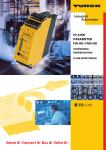
User manual deltaflowC
User Manual
del
deltaflowC – mass flow meter for Gases
systec Controls GmbH
Lindberghstrasse 4, 82178 Puchheim, Germany
Telefon +49-(0)89 - 80906-0, Telefax +49-(0)89 - 80906-200
info@systec -controls.de
http://www.systec-controls.de
Seite
Rev. 1.0 27.07.2011
1
User manual deltaflowC
1. Welcome to systec Controls
Thank you very much for using deltaflowC. deltaflowC is a state-of-the art mass flow meter for gases.
This user manual guides you through the installation and parameterization step-by-step
2. Index
1. Welcome to systec Controls ..............................................................................................................2
2. Index .................................................................................................................................................2
3. Scope of Supply / Unpacking ............................................................................................................3
4. CE / Electromagnetic compatibility ....................................................................................................3
5. Mounting ...........................................................................................................................................4
6. Recommended mounting position .....................................................................................................7
7. Wiring................................................................................................................................................8
8. Parameterization ...............................................................................................................................9
8.1. deltaflowC Designer Software ........................................................................................................9
8.2. Parameterization step-by-step .......................................................................................................9
8.3. Choose measurement span, outputs and damping ...................................................................... 13
9. Span / Accuracy .............................................................................................................................. 18
10. Specification ................................................................................................................................ 21
11. Calibration.................................................................................................................................... 22
12. Type Code ................................................................................................................................... 22
13. Maintenance ................................................................................................................................ 23
14. Further information....................................................................................................................... 23
15. Any questions? ............................................................................................................................ 23
16. Annex........................................................................................................................................... 24
Table 1 Measurement accuracies .......................................................................................................... 20
Table 2 Specification.............................................................................................................................. 21
Table 3 deltaflowC Type code................................................................................................................ 22
Table 4 Densities of various gases at standard conditions ..................................................................... 24
Picture 1 Dimensions ...............................................................................................................................4
Picture 2 Example, deltaflow for bigger pipes...........................................................................................5
Picture 3 Example, deltaflow for smaller pipes, profile touches opposite pipe wall ...................................5
Picture 4 Straight run requirements.........................................................................................................7
Picture 5 cable room ................................................................................................................................8
Picture 6 Selection of type of probe .........................................................................................................9
Picture 7 Select Media ........................................................................................................................... 10
Picture 8 Selection of customized gases................................................................................................ 11
Picture 9 Eingabe Prozessparameter..................................................................................................... 12
Picture 10 Choose your span ................................................................................................................. 13
Picture 11 Select signal damping ........................................................................................................... 14
Picture 12 Select Outputs ...................................................................................................................... 15
Picture 13 DIP-Switches......................................................................................................................... 16
Picture 14 Example of printout of parameter settings............................................................................. 17
Picture 15 Estimation of span................................................................................................................. 18
Picture 16 Example: Selection of end of span for pipe ID=200mm......................................................... 19
systec Controls GmbH
Lindberghstrasse 4, 82178 Puchheim, Germany
Telefon +49-(0)89 - 80906-0, Telefax +49-(0)89 - 80906-200
info@systec -controls.de
http://www.systec-controls.de
Seite
Rev. 1.0 27.07.2011
2
User manual deltaflowC
3. Scope of Supply / Unpacking
Please unpack carefully. The deltaflowC comes together with a separated weld-in cutting ring stud.
Please check all components for damages and report any damages to the forwarder within 24 hours.
Please compare the content of the package to your order confirmation and the delivery note. Please
also compare the model code to the model code stated in the order confirmation and/or the delivery
note. Please report any deviations to systec Controls.
4. CE / Electromagnetic compatibility
deltaflowC was tested and is in agreement with the following standards
2006/95/EG Low Voltage Directive
2004/108/EG Electromagnetic Compatibility Directive
EN 61000-6-3: 2007-09
EN 61000-6-4: 2007-09 I
DIN EN 55022: 2008-05
EN 55011/ - 2010-05
EN 55014-1: 2010-0
EN 61000-6-1: 2007-10
EN 61000-6-2: 2006-03
EN 55014-2: 2009-06
EN 55024: 2003-10
EN 61000-4-2:2009
EN 61000-4-3: 2008-06
EN 61000-4-4: 2010-11
EN 61000-4-5:95+A1:01
EN 61000-4-6_2009-12
systec Controls GmbH
Lindberghstrasse 4, 82178 Puchheim, Germany
Telefon +49-(0)89 - 80906-0, Telefax +49-(0)89 - 80906-200
info@systec -controls.de
http://www.systec-controls.de
Seite
Rev. 1.0 27.07.2011
3
User manual deltaflowC
5. Mounting
Picture 1 Dimensions
deltaflowC is feed into your pipe via a weld-in cutting ring stud (Picture 2). Please use the cutting ring stud
from systec Controls.
The deltaflowC is feed into the pipe either until it hits the other side of the pipe (see Picture 3) or until the
probe’s neck reaches and is blocked by the cutting ring stud (see Picture 2). This means that the position
of the dp tappings within the pipe depends on the pipe size. This is automatically considered by the design software when doing the parameterization.
On the deltaflowC lable ou will find a printed arrow indicating the correct mounting position. Please
mount the deltaflow in that way that the arrow corresponds to the actual flow direction of your media
(Picture 2)
The cover can be rotated if necessary.
systec Controls GmbH
Lindberghstrasse 4, 82178 Puchheim, Germany
Telefon +49-(0)89 - 80906-0, Telefax +49-(0)89 - 80906-200
info@systec -controls.de
http://www.systec-controls.de
Seite
Rev. 1.0 27.07.2011
4
User manual deltaflowC
(Removable) Cover with cable gland
Flow identification, arrow must be follow
your flow
Weld-in cutting ring stud (H=30mm, Inner diameter=15mm,requires hole 21.5mm (+/-0.5mm)
Max. Insertion length 100mm
dp-tappings („holes“)
Picture 2 Example, deltaflow for bigger pipes
Picture 3 Example, deltaflow for smaller pipes, profile touches opposite pipe wall
systec Controls GmbH
Lindberghstrasse 4, 82178 Puchheim, Germany
Telefon +49-(0)89 - 80906-0, Telefax +49-(0)89 - 80906-200
info@systec -controls.de
http://www.systec-controls.de
Seite
Rev. 1.0 27.07.2011
5
User manual deltaflowC
Pipe
Vertical
Illustration
Designation
The probe is installed in a horizontal
position or with a slight incline (0..3°)
toward the probe’s tip. This ensures a
free drain back of any condensate.
0…3°
Horizontal, recommended mounting
-30°…30°
Horizontal, alternative mounting
The probe is installed vertically from top
or at an angle between -30°…30°. This
ensures a free drain back of any condensate.
The probe is installed in a horizontal
position or with a slight incline (0..3°)
toward the probe’s tip. This ensures a
free drain back of any condensate.
0…3°
Tabelle 1 Mounting positions
systec Controls GmbH
Lindberghstrasse 4, 82178 Puchheim, Germany
Telefon +49-(0)89 - 80906-0, Telefax +49-(0)89 - 80906-200
info@systec -controls.de
http://www.systec-controls.de
Seite
Rev. 1.0 27.07.2011
6
User manual deltaflowC
6. Recommended mounting position
To achieve the best possible accuracy the recommended straight runs (ID=internal diameter) given by
Picture 4 should be fulfilled. Choosing the wrong position of mounting might result in poor measurement
results. If you should feel not comfortable with your available straight runs we are happy to find the best
position for your deltaflowC.
90° Ellbow, 15x Pipe ID
2x Pipe ID
7
Reduction, 7xID
2xID
Two 90° Ellbow (same level), 20xID 2xID
Widening, 15xID
Two 90° Ellbow (different level), 20xID 2xID
2xID
Valve 30xID30
2xID
Picture 4 Straight run requirements
Recommended Filler Materials
The material of cutting ring stud can be verified at order confirmation.
Material of Pipe
Material of stud
WIG
Carbon steel (St. 35.8)
Carbon steel (St. 35.8) DMO-IG
Carbon steel (St. 35.8)
Stainless steel
A7-A-IG
(1.4571)
Stainless steel (1.4571) Stainless steel
SAS4-IG
(1.4571)
Electrodes
FoxEV50
FoxA7-A-IG
Oxyacetylene
BW XII
FoxSAS4-IG
Tabelle 2 Filler Material
systec Controls GmbH
Lindberghstrasse 4, 82178 Puchheim, Germany
Telefon +49-(0)89 - 80906-0, Telefax +49-(0)89 - 80906-200
info@systec -controls.de
http://www.systec-controls.de
Seite
Rev. 1.0 27.07.2011
7
User manual deltaflowC
7. Wiring
For wiring please remove cover (see Picture 2) to access the cable room. Inside of cable room you have
screw terminals and DIP switches for set-up and connection of power supply and outptus (see Picture 5
Screw terminals
DIP switches
Picture 5 cable room
The 6 DIP switches can be used to set-up span, damping and outputs. The parameterization is done
using the designer software (see chapter 8) and gives then the setting of the DIP swiches for your
application.
For power supply please use 18-36 VDC.
systec Controls GmbH
Lindberghstrasse 4, 82178 Puchheim, Germany
Telefon +49-(0)89 - 80906-0, Telefax +49-(0)89 - 80906-200
info@systec -controls.de
http://www.systec-controls.de
Seite
Rev. 1.0 27.07.2011
8
User manual deltaflowC
8. Parameterization
8.1. deltaflowC Designer Software
The parameterization is simple and fast and is done by using the deltaflowC designer software. You can
download the designer software free of charge from our webpage.
With the designer software you can set your process parameters and outputs and you can choose flow
range and signal damping.
8.2. Parameterization step-by-step
Picture 6 Selection of type of probe
Please select type DFC….. at the „Select Type“ box (see Picture 6Picture 6)
systec Controls GmbH
Lindberghstrasse 4, 82178 Puchheim, Germany
Telefon +49-(0)89 - 80906-0, Telefax +49-(0)89 - 80906-200
info@systec -controls.de
http://www.systec-controls.de
Seite
Rev. 1.0 27.07.2011
9
User manual deltaflowC
^
Picture 7 Select Media
Now please select your media. You already have the most common gases in the internal data base (see
Picture 7) like air, nitrogen, carbon dioxide….
systec Controls GmbH
Lindberghstrasse 4, 82178 Puchheim, Germany
Telefon +49-(0)89 - 80906-0, Telefax +49-(0)89 - 80906-200
info@systec -controls.de
http://www.systec-controls.de
Seite
Rev. 1.0 27.07.2011
10
User manual deltaflowC
Picture 8 Selection of customized gases
If your media should not be in the data base please choose „other gas“. Then you need to put in the
density at standard conditions. Common densities can be found in the attachment. Normally standard
conditions are related to 1013.25mbar and 0°C. If y ou have densities at different standard conditions
you can change the standard conditions by clicking at the arrow next to “Standard Density”. You will find
densities for common gases also in the Annex.
systec Controls GmbH
Lindberghstrasse 4, 82178 Puchheim, Germany
Telefon +49-(0)89 - 80906-0, Telefax +49-(0)89 - 80906-200
info@systec -controls.de
http://www.systec-controls.de
Seite
Rev. 1.0 27.07.2011
11
User manual deltaflowC
Picture 9 Specification of process parameters
Now please enter pipe diameter (inner) or dimensions (inner) of your channel and design process data.
You can choose different units for your process data.
The ImproveIT-Factor (default value = 1) normally does not have to be changed. The ImproveIT-factor
can be used to improve accuracy in case of specific short straight runs (required straight runs see chapter 6). Please ask your systec dealer for a proper ImproveIt-factor.
systec Controls GmbH
Lindberghstrasse 4, 82178 Puchheim, Germany
Telefon +49-(0)89 - 80906-0, Telefax +49-(0)89 - 80906-200
info@systec -controls.de
http://www.systec-controls.de
Seite
Rev. 1.0 27.07.2011
12
User manual deltaflowC
8.3. Choose measurement span, outputs and damping
Picture 10 Choose your span
After setting your pipe and process data the designer software calculates the available spans for your
mass flow signal. You can choose from up to 4 different spans. You can select different units. Please
choose the proper span for your applications. The value given by the software (in Picture 10 e.g. “low
flow” = 54.66 kg/h) indicates the end of span and so the value which corresponds to 20mA or 10V (see
Picture 12 for setting outputs)
systec Controls GmbH
Lindberghstrasse 4, 82178 Puchheim, Germany
Telefon +49-(0)89 - 80906-0, Telefax +49-(0)89 - 80906-200
info@systec -controls.de
http://www.systec-controls.de
Seite
Rev. 1.0 27.07.2011
13
User manual deltaflowC
Picture 11 Select signal damping
Please select the signal damping as shown in Picture 11. You can choose from 4 different values between 0.2sec to 10sec. It is a T63-damping.
Example: Damping = 3 sec. If there is a change in flow the signal output will reach a level of 63% of the
current flow after 3 seconds. 0.2sec is for (rare) applications which requires immediate response (“fast
mode”). For standard applications 3 or 10 sec. had proved to be a proper damping.
systec Controls GmbH
Lindberghstrasse 4, 82178 Puchheim, Germany
Telefon +49-(0)89 - 80906-0, Telefax +49-(0)89 - 80906-200
info@systec -controls.de
http://www.systec-controls.de
Seite
Rev. 1.0 27.07.2011
14
User manual deltaflowC
Picture 12 Select Outputs
deltaflowC offers two signal outputs for mass flow and static pressure or temperature. For flow or temperature you can use the 4…20mA output (3-wires). For flow or pressure you can (additionally) use the
0…10VDC output. In the designer software you can allocate the outputs to the related measured variable. In the example shown in Picture 12 you would use 4…20mA output for mass flow (4..20mA =
0..54.66 kg/h) and the 0..10VDC output for static pressure.
The span of mass flow corresponds to the span choosen before (see Picture 10). The span for temperature and static pressure is fixed to 4…20mA = -40…..500°C respectively 0…10VDC = 0…14bar.
systec Controls GmbH
Lindberghstrasse 4, 82178 Puchheim, Germany
Telefon +49-(0)89 - 80906-0, Telefax +49-(0)89 - 80906-200
info@systec -controls.de
http://www.systec-controls.de
Seite
Rev. 1.0 27.07.2011
15
User manual deltaflowC
Picture 13 DIP-Switches
Now all necessary settings have been done. As the result from this the designer software gives you the
setting of the DIP-switches. Please set the DIP-switches in the cable room (see Picture 5) of your deltaflow according to the settings given by the designer software
The designer software offers a „print“ function which allows you to print out your settings (example see
for your documentation.
Picture 13)
systec Controls GmbH
Lindberghstrasse 4, 82178 Puchheim, Germany
Telefon +49-(0)89 - 80906-0, Telefax +49-(0)89 - 80906-200
info@systec -controls.de
http://www.systec-controls.de
Seite
Rev. 1.0 27.07.2011
16
User manual deltaflowC
Picture 14 Example of printout of parameter settings
systec Controls GmbH
Lindberghstrasse 4, 82178 Puchheim, Germany
Telefon +49-(0)89 - 80906-0, Telefax +49-(0)89 - 80906-200
info@systec -controls.de
http://www.systec-controls.de
Seite
Rev. 1.0 27.07.2011
17
User manual deltaflowC
9. Span / Accuracy
deltaflowC offers you up to 4 different spans from „low flow“ to „high“. Using Picture 15 you can estimate
the upper range value (end of span) for your pipe size to check feasibility of applications.
deltaflowC
10,000,000
Very low
Low
Medium
1,000,000
High
Messbereich [Nm³/h]
100,000
10,000
1,000
100
10
10
100
Innendurchmesser [mm]
1000
10000
Inner diameter [mm]
Picture 15 Estimation of span
systec Controls GmbH
Lindberghstrasse 4, 82178 Puchheim, Germany
Telefon +49-(0)89 - 80906-0, Telefax +49-(0)89 - 80906-200
info@systec -controls.de
http://www.systec-controls.de
Seite
Rev. 1.0 27.07.2011
18
User manual deltaflowC
deltaflowC
10,000,000
Very low
Low
Medium
1,000,000
High
Messbereich [Nm³/h]
100,000
10,000
1,000
100
10
10
100
Innendurchmesser
[mm]
Inner diameter [mm]
1000
10000
Picture 16 Example: Selection of end of span for pipe ID=200mm
The example from Picture 16 should illustrate this. Selecting a pipe diameter of 200mm would end up in a
span of app. 5000 Nm3/h (green curve = “low”). For this pipe you could also choose between other
spans from “very low” (blue curve = app. 1400 Nm3/h) to “medium” (orange curve ) = app. 15000Nm3/h)
and “high” (red curve = app. 50,000 Nm3/h). The graph shown in Picture 16 is mainly to check feasibility
of deltaflowC for your application but also to check accuracies (next chapter)
systec Controls GmbH
Lindberghstrasse 4, 82178 Puchheim, Germany
Telefon +49-(0)89 - 80906-0, Telefax +49-(0)89 - 80906-200
info@systec -controls.de
http://www.systec-controls.de
Seite
Rev. 1.0 27.07.2011
19
User manual deltaflowC
Two different accuracy classes are available as shown in Table 1.
Typ
Standard
(Code …..DS…..see Table 3)
Accuracy
4% of reading
Designation
Starting from 10% of low-flow
span
High-Accuracy
(Code ……DH…see Table 3)
2% of reading
2% Starting from 15% of lowflow span respectively 4% starting from 7% of low-flow-span
Table 1 Measurement accuracies
The accuracy statement always corresponds to the “low”- curve (green curve) which you can pick out
from diagram shown in Picture 15
Example: In the example shown in Picture 16 you have an end of span of 5000 Nm3/h. The standard type
reaches an accuracy of 4% starting from 10% of the choosen span (here 500 Nm3/h). The high accuracy type reaches an accuracy of 4% starting from 7% of choosen span (here 350Nm3/h) and an accuracy of 2% starting from 15% of span (here 750 Nm3/h).
systec Controls GmbH
Lindberghstrasse 4, 82178 Puchheim, Germany
Telefon +49-(0)89 - 80906-0, Telefax +49-(0)89 - 80906-200
info@systec -controls.de
http://www.systec-controls.de
Seite
Rev. 1.0 27.07.2011
20
User manual deltaflowC
10. Specification
Metering
Principle
Measured quantities
Span
Accuracy
Differential pressure with pressure and temperature compensation
Mass flow, temperature, static pressre
1:25
Standard type: Starting from 10% of low-flow span
High-accuracy: 2% Starting from 15% of low-flow
span respectively 4% starting from 7% of low-flowspan
Operating conditions
Media
Pressure
Temperature of Media
Ambient temperature
Material
Material enclosure
Burst Pressure
Probe length
Pipe sizes
Electrical connector
Power supply
Outputs
Degree of Protection
Gases, non-explosive / non-corrosive
10 bar
-80…250°C
-40…120°C
SS316Ti
SS316Ti, painted
16 bar
Max. insertion length 100mm
Starting from DN20 (2/3“)
4 terminal screws
18 – 36 VDC
1x 4…20mA (3-wire)
1x 0…10VDC
IP67
Table 2 Specification
systec Controls GmbH
Lindberghstrasse 4, 82178 Puchheim, Germany
Telefon +49-(0)89 - 80906-0, Telefax +49-(0)89 - 80906-200
info@systec -controls.de
http://www.systec-controls.de
Seite
Rev. 1.0 27.07.2011
21
User manual deltaflowC
11. Calibration
The high-accuracy type always includes a calibration which is done at our traceable test rig (air).
12. Type Code
The type code is printed on the lable of your deltaflowC. Using the type code shown in Table 3 you can
easily reorder the proper model or choose the right model for other applications.
Please also use your online formular to place your inquiries or orders or call us at
+49 89 80 90 6 0
DFC
P10
V32
V50
V80
PWS
PWC
PF
notes
options
Accuracy
Process connection
Basic Type
http://www.systec-controls.de/253-1-deltaflowc---mass-flow-meter-for-gases.html
Thank you
deltaflowC Massflow Sensor
Probe 100mm insertion depth
CompactVenturi DN32PN16
CompactVenturi DN50PN16
CompactVenturi DN80PN16
weld in cutring SS316 (only Basic Type P10)
weld in cutring CS (only Basic Type P10)
Interflange Connection PN16, RF
DS
Standard type
DH
High Accuracy Type (OC required)
O- none
OC calibration protokoll (3 points)
Table 3 deltaflowC Type code
systec Controls GmbH
Lindberghstrasse 4, 82178 Puchheim, Germany
Telefon +49-(0)89 - 80906-0, Telefax +49-(0)89 - 80906-200
info@systec -controls.de
http://www.systec-controls.de
Seite
Rev. 1.0 27.07.2011
22
User manual deltaflowC
13. Maintenance
deltaflowC offers long-term stability and does normally not require maintenance.
14. Further information
These documents can be downloaded from our webpage or can be obtained from our sales agents.
•
•
deltaflowC Brochure
deltaflowC parameterization software (Designer)
http://www.systec-controls.de
15. Any questions?
We are happy to support you. Please do not hesitate to use the expertise and application know-how of
your sales engineers and sales agents.
You can check our web page to find your local systec agent.
http://www.systec-controls.de/5-1-contact-und-information.html
Of course we are always happy to take your calls in our headquarter in Puchheim, Germany.
systec Controls Hotline:
+49-(0)89 - 80 90 6 - 108
systec Controls GmbH
Lindberghstrasse 4, 82178 Puchheim, Germany
Telefon +49-(0)89 - 80906-0, Telefax +49-(0)89 - 80906-200
info@systec -controls.de
http://www.systec-controls.de
Seite
Rev. 1.0 27.07.2011
23
User manual deltaflowC
16. Annex
Densities of different gases at standard conditions (0°C, 1013.25 mbar) in kg/m3)
Table 4 Densities of various gases at standard conditions
systec Controls GmbH
Lindberghstrasse 4, 82178 Puchheim, Germany
Telefon +49-(0)89 - 80906-0, Telefax +49-(0)89 - 80906-200
info@systec -controls.de
http://www.systec-controls.de
Seite
Rev. 1.0 27.07.2011
24