1
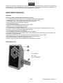
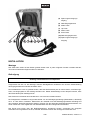
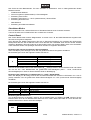
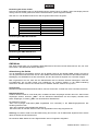
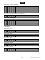
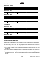
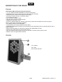
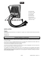
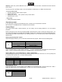
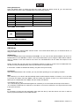
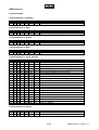
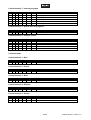
BEDIENUNGSANLEITUNG
USER MANUAL
WL-18 IP65
LED Architectural
Spot
Für weiteren Gebrauch aufbewahren!
Keep this manual for future needs!
© Copyright
Nachdruck verboten!
Reproduction prohibited!
Inhaltsverzeichnis
Table of contents
EINFÜHRUNG ................................................................................................................................................... 3
Lieferumfang .................................................................................................................................................. 3
SICHERHEITSHINWEISE................................................................................................................................. 3
BESTIMMUNGSGEMÄßE VERWENDUNG..................................................................................................... 5
GERÄTEBESCHREIBUNG............................................................................................................................... 6
Features ......................................................................................................................................................... 6
Geräteübersicht.............................................................................................................................................. 6
INSTALLATION ................................................................................................................................................ 7
Montage ......................................................................................................................................................... 7
Befestigung .................................................................................................................................................... 7
DMX512-Ansteuerung.................................................................................................................................... 8
Master/Slave-Betrieb...................................................................................................................................... 9
Anschluss ans Netz........................................................................................................................................ 9
BEDIENUNG ..................................................................................................................................................... 9
Standalone-Modus ....................................................................................................................................... 10
Control Board ............................................................................................................................................... 10
DMX-Mode ................................................................................................................................................... 11
DMX-Protokoll .............................................................................................................................................. 12
REINIGUNG UND WARTUNG........................................................................................................................ 14
TECHNISCHE DATEN .................................................................................................................................... 15
INTRODUCTION ............................................................................................................................................. 16
Delivery includes .......................................................................................................................................... 16
SAFETY INSTRUCTIONS............................................................................................................................... 16
OPERATING DETERMINATIONS.................................................................................................................. 18
DESCRIPTION OF THE DEVICE ................................................................................................................... 19
Features ....................................................................................................................................................... 19
Overview ...................................................................................................................................................... 19
INSTALLATION .............................................................................................................................................. 20
Rigging ......................................................................................................................................................... 20
Attachment ................................................................................................................................................... 20
DMX512 control ........................................................................................................................................... 21
Master/Slave operation ................................................................................................................................ 22
Connection with the mains ........................................................................................................................... 22
OPERATION.................................................................................................................................................... 22
Stand-alone mode........................................................................................................................................ 23
Control Board ............................................................................................................................................... 23
DMX-Mode ................................................................................................................................................... 24
DMX-protocol ............................................................................................................................................... 25
CLEANING AND MAINTENANCE ................................................................................................................. 27
TECHNICAL SPECIFICATIONS..................................................................................................................... 28
Diese Bedienungsanleitung gilt für die Artikelnummer 51833555
This user manual is valid for the article number 51833555
Das neueste Update dieser Bedienungsanleitung finden Sie im Internet unter:
You can find the latest update of this user manual in the Internet under:
www.futurelight.com
2/28
00066130.DOC, Version 1.0
BEDIENUNGSANLEITUNG
WL-18 IP65
LED-Architektur-Scheinwerfer
Lesen Sie vor der ersten Inbetriebnahme zur eigenen Sicherheit diese Bedienungsanleitung
sorgfältig durch!
Alle Personen, die mit der Aufstellung, Inbetriebnahme, Bedienung, Wartung und Instandhaltung dieses
Gerätes zu tun haben, müssen
- entsprechend qualifiziert sein
- diese Bedienungsanleitung genau beachten
- die Bedienungsanleitung als Teil des Produkts betrachten
- die Bedienungsanleitung während der Lebensdauer des Produkts behalten
- die Bedienungsanleitung an jeden nachfolgenden Besitzer oder Benutzer des Produkts weitergeben
- sich die letzte Version der Anleitung im Internet herunter laden
EINFÜHRUNG
Wir freuen uns, dass Sie sich für einen FUTURELIGHT WL-18 IP65 entschieden haben. Wenn Sie
nachfolgende Hinweise beachten, sind wir sicher, dass Sie lange Zeit Freude an Ihrem Kauf haben werden.
Nehmen Sie das Gerät aus der Verpackung.
Lieferumfang
1
1
1
1
1
Gerät
Bedienungsanleitung
Anschlussleitung
DMX-IN-Kabel
DMX-OUT-Kabel
Verschlusskappen
SICHERHEITSHINWEISE
ACHTUNG!
Seien Sie besonders vorsichtig beim Umgang mit gefährlicher Netzspannung. Bei dieser Spannung können Sie einen lebensgefährlichen elektrischen Schlag erhalten!
Dieses Gerät hat das Werk in sicherheitstechnisch einwandfreiem Zustand verlassen. Um diesen Zustand zu
erhalten und einen gefahrlosen Betrieb sicherzustellen, muss der Anwender die Sicherheitshinweise und die
Warnvermerke unbedingt beachten, die in dieser Bedienungsanleitung enthalten sind.
3/28
00066130.DOC, Version 1.0
Unbedingt lesen:
Bei Schäden, die durch Nichtbeachtung der Anleitung verursacht werden, erlischt der Garantieanspruch. Für daraus resultierende Folgeschäden übernimmt der Hersteller keine Haftung.
Das Gerät darf nicht in Betrieb genommen werden, nachdem es von einem kalten in einen warmen Raum
gebracht wurde. Das dabei entstehende Kondenswasser kann unter Umständen Ihr Gerät zerstören. Lassen
Sie das Gerät solange uneingeschaltet, bis es Zimmertemperatur erreicht hat!
Bitte überprüfen Sie vor der ersten Inbetriebnahme, ob kein offensichtlicher Transportschaden vorliegt.
Sollten Sie Schäden an der Netzleitung oder am Gehäuse entdecken, nehmen Sie das Gerät nicht in Betrieb
und setzen sich bitte mit Ihrem Fachhändler in Verbindung.
Der Aufbau entspricht der Schutzklasse I. Der Netzstecker darf nur an eine Schutzkontakt-Steckdose
angeschlossen werden, deren Spannung und Frequenz mit dem Typenschild des Gerätes genau
übereinstimmt. Ungeeignete Spannungen und ungeeignete Steckdosen können zur Zerstörung des Gerätes
und zu tödlichen Stromschlägen führen.
Den Netzstecker immer als letztes einstecken. Der Netzstecker muss dabei gewaltfrei eingesetzt werden.
Achten Sie auf einen festen Sitz des Netzsteckers.
Lassen Sie die Netzleitung nicht mit anderen Kabeln in Kontakt kommen! Seien Sie vorsichtig beim Umgang
mit Netzleitungen und -anschlüssen. Fassen Sie diese Teile nie mit feuchten Händen an! Feuchte Hände
können tödliche Stromschläge zur Folge haben.
Netzleitungen nicht verändern, knicken, mechanisch belasten, durch Druck belasten, ziehen, erhitzen und
nicht in die Nähe von Hitze- oder Kältequellen bringen. Bei Missachtung kann es zu Beschädigungen der
Netzleitung, zu Brand oder zu tödlichen Stromschlägen kommen.
Die Kabeleinführung oder die Kupplung am Gerät dürfen nicht durch Zug belastet werden. Es muss stets
eine ausreichende Kabellänge zum Gerät hin vorhanden sein. Andernfalls kann das Kabel beschädigt
werden, was zu tödlichen Stromschlägen führen kann.
Achten Sie darauf, dass die Netzleitung nicht gequetscht oder durch scharfe Kanten beschädigt werden
kann. Überprüfen Sie das Gerät und die Netzleitung in regelmäßigen Abständen auf Beschädigungen.
Werden Verlängerungsleitungen verwendet muss sichergestellt werden, dass der Adernquerschnitt für die
benötigte Stromzufuhr des Gerätes zugelassen ist. Alle Warnhinweise für die Netzleitung gelten auch für
evtl. Verlängerungsleitungen.
Gerät bei Nichtbenutzung und vor jeder Reinigung vom Netz trennen! Fassen Sie dazu den Netzstecker an
der Grifffläche an und ziehen Sie niemals an der Netzleitung! Ansonsten kann das Kabel und der Stecker
beschädigt werden was zu tödlichen Stromschlägen führen kann. Sind Stecker oder Geräteschalter, z. B.
durch Einbau nicht erreichbar, so muss netzseitig eine allpolige Abschaltung vorgenommen werden.
Wenn der Netzstecker oder das Gerät staubig ist, dann muss es außer Betrieb genommen werden, der
Stromkreis muss allpolig unterbrochen werden und das Gerät mit einem trockenen Tuch gereinigt werden.
Staub kann die Isolation reduzieren, was zu tödlichen Stromschlägen führen kann. Stärkere Verschmutzungen im und am Gerät dürfen nur von einem Fachmann beseitigt werden.
In das Gerät dürfen keine fremden Gegenstände gelangen. Dies gilt insbesondere für Metallteile. Sollten
auch nur kleinste Metallteile wie Heft- und Büroklammern oder gröbere Metallspäne in das Gerät gelangen,
so ist das Gerät sofort außer Betrieb zu nehmen und allpolig vom Netz zu trennen. Durch Metallteile
hervorgerufene Fehlfunktionen und Kurzschlüsse können tödliche Verletzungen zur Folge haben.
GESUNDHEITSRISIKO!
Blicken Sie niemals direkt in die Lichtquelle, da bei empfindlichen Menschen u. U.
epileptische Anfälle ausgelöst werden können (gilt besonders für Epileptiker)!
Kinder und Laien vom Gerät fern halten!
Das Gerät darf niemals unbeaufsichtigt betrieben werden!
4/28
00066130.DOC, Version 1.0
BESTIMMUNGSGEMÄßE VERWENDUNG
Bei diesem Gerät handelt es sich um eine ortsfeste Leuchte für allgemeine Zwecke. Dieses Produkt ist nur
für den Anschluss an 230 V, 50 Hz Wechselspannung zugelassen.
Das Gerät ist gegen Strahlwasser geschützt (Schutzart IP X5) und kann deshalb sowohl in Innenräumen als
auch im Freien verwendet werden. Um diese Schutzart zu gewährleisten, müssen nach Öffnen des Gerätes
evtl. vorhandene Gummidichtungen auf Beschädigungen überprüft und ordnungsgemäß montiert werden.
Der Installateur muss sicherstellen, dass bei Verwendung im Freien immer eine Gummischlauchleitung
H05RN-F oder HO5RR-F angeschlossen wird. Bei Verlegung im Erdreich muss ein Erdkabel NYY verwendet
werden!
Alle geltenden Vorschriften zur Installation von Kabeln im Freien bzw. im Erdreich müssen unbedingt
eingehalten werden!
Die Umgebungstemperatur muss zwischen -25° C und +45° C liegen. Halten Sie das Gerät von direkter
Sonneneinstrahlung (auch beim Transport in geschlossenen Wägen) und Heizkörpern fern.
Die maximale relative Luftfeuchte beträgt 100 % bei einer Umgebungstemperatur von 25° C.
Dieses Gerät darf nur in einer Höhenlage zwischen -20 und 2000 m über NN betrieben werden.
Dieses Gerät ist für professionelle Anwendungen für den Außenbereich vorgesehen.
Vermeiden Sie Erschütterungen und jegliche Gewaltanwendung bei der Installation oder Inbetriebnahme des
Gerätes.
Vergewissern Sie sich bei der Wahl des Installationsortes darauf, dass keine Kabel frei herumliegen. Sie
gefährden Ihre eigene und die Sicherheit Dritter!
Die maximale Umgebungstemperatur Ta = 45° C darf niemals überschritten werden.
Das F-Zeichen bedeutet: Diese Leuchte darf auf normal entflammbaren Oberflächen installiert werden.
- - -m
bezeichnet den Mindestabstand zu beleuchteten Gegenständen. Der Abstand
Das Bildzeichen
zwischen Lichtaustritt und der zu beleuchteten Fläche darf 0,1 Meter nicht unterschreiten!
Das Gerät darf nur über den Montagebügel installiert werden. Um eine gute Luftzirkulation zu gewährleisten,
muss um das Gerät ein Freiraum von mindestens 50 cm eingehalten werden.
Das Gehäuse darf niemals umliegende Gegenstände oder Flächen berühren!
Achten Sie bei der Montage, beim Abbau und bei der Durchführung von Servicearbeiten darauf, dass der
Bereich unterhalb des Montageortes abgesperrt ist.
Betreiben Sie das Gerät nur, nachdem Sie sich vergewissert haben, dass alle Gummidichtungen
ordnungsgemäß montiert, das Gehäuse fest verschlossen ist und alle nötigen Schrauben gleichmäßig
angezogen wurden.
Nehmen Sie das Gerät erst in Betrieb, nachdem Sie sich mit seinen Funktionen vertraut gemacht haben.
Lassen Sie das Gerät nicht von Personen bedienen, die sich nicht mit dem Gerät auskennen. Wenn Geräte
nicht mehr korrekt funktionieren, ist das meist das Ergebnis von unsachgemäßer Bedienung!
Reinigen Sie das Gerät niemals mit Lösungsmitteln oder scharfen Reinigungsmitteln, sondern verwenden
Sie ein weiches und angefeuchtetes Tuch.
Soll das Gerät transportiert werden, verwenden Sie bitte die Originalverpackung, um Transportschäden zu
vermeiden. Achten Sie bitte unbedingt darauf, dass das Gerät im Lieferzustand verpackt wird.
Beachten Sie bitte, dass eigenmächtige Veränderungen an dem Gerät aus Sicherheitsgründen verboten
sind.
Der Serienbarcode darf niemals vom Gerät entfernt werden, da ansonsten der Garantieanspruch erlischt.
5/28
00066130.DOC, Version 1.0
Wird das Gerät anders verwendet als in dieser Bedienungsanleitung beschrieben, kann dies zu Schäden am
Produkt führen und der Garantieanspruch erlischt. Außerdem ist jede andere Verwendung mit Gefahren, wie
z. B. Kurzschluss, Brand, elektrischem Schlag, Abstürzen etc. verbunden.
GERÄTEBESCHREIBUNG
Features
Vielseitiger LED Architektur-Scheinwerfer mit 3-W-TCLs
• 3, 4, 5 oder 9 DMX-Kanäle wählbar für verschiedene Anwendungsmöglichkeiten
• Ausgestattet mit 18 x 3in1-Tricolor-LED in den Farben rot, grün und blau
• Flache Gehäuseform für minimalen Platzbedarf bei der Montage
• Äußerst kompaktes und formschönes Gehäuse
• Zur Fassadenbeleuchtung
• Reine Konvektionskühlung über Kühlrippen, keine Lüfter
• Präzisions Druckguss-Gehäuse aus Aluminium
• Für den Gebrauch im Freien geeignet, IP 65
• Funktionen: stufenlose RGB-Farbmischung, feste Farben, programmierte Farbtemperaturwerte, interne
Programme, Dimmer, Strobe-Effekt, Master/Slave-Betrieb
• Vier verschiedene Dimmerkurven einstellbar
• Geschwindigkeit der Farbwechsel und Strobe-Effekt einstellbar
• Komfortable Adressierung und Einstellung über Control-Board mit vier Bedientasten und LED-Anzeige mit
vierstelliger 14-Segmentanzeige
• DMX-gesteuerter Betrieb oder Standalone-Betrieb mit Master-/Slave-Funktion möglich
• Durchschleifausgang zur Spannungsversorgung eines weiteren Gerätes
• Nach jeweils 8 Geräten muss neu eingespeist werden
• DMX512-Steuerung über jeden handelsüblichen DMX-Controller möglich
Geräteübersicht
(1) Gehäuse
(2) LEDs
(3) Montagebügel
6/28
00066130.DOC, Version 1.0
(4) Spannungsversorgungseingang
(5) DMX-Eingangsbuchse
(6) Mode-Taste
(7) Up-Taste
(8) Down-Taste
(9) Enter-Taste
(10) DMX-Ausgangsbuchse
(11) Spannungsversorgungsausgang
INSTALLATION
Montage
Das Gerät kann direkt auf den Boden gestellt werden oder in jeder möglichen Position installiert werden,
ohne seine funktionellen Eigenschaften zu verändern.
Befestigung
Achtung: Festinstallation wird empfohlen!
Vergewissern Sie sich vor der Montage, dass die Montagefläche mindestens die 10-fache Punktbelastung
des Eigengewichtes des Gerätes aushalten kann.
Der Installationsort muss so gewählt werden, dass das Gerät absolut plan an einem festen, erschütterungsfreien, schwingungsarmen Ort befestigt werden kann. Mittels Wasserwaage muss überprüft werden, dass
das Gerät absolut plan befestigt wurde.
Das Gerät muss außerhalb des Handbereichs von Personen installiert werden.
Die Festigkeit der Installation hängt entscheidend von der Befestigungsunterlage (Bausubstanz, Werkstoff)
wie z. B. Holz, Beton, Gasbeton, Mauersteine ab. Deshalb muss das Befestigungsmaterial unbedingt auf
den jeweiligen Werkstoff abgestimmt werden. Erfragen Sie die passende Dübel/Schraubenkombination von
einem Fachmann unter Angabe der max. Belastbarkeit und des vorliegenden Werkstoffes.
Das Gerät muss immer über alle Befestigungslöcher angebracht werden. Verwenden Sie geeignete
Schrauben und vergewissern Sie sich, dass die Schrauben fest mit dem Untergrund verbunden sind.
7/28
00066130.DOC, Version 1.0
Vorgehensweise:
Schritt 1: An dem Befestigungsbügel des Gerätes befinden sich die Löcher zur Installation.
Schritt 2: Halten Sie das Gerät mit dem Befestigungsbügel an die Stelle, wo es installiert werden soll.
Schritt 3: Markieren Sie Ihre Bohrlöcher mit einem Bleistift oder einem geeigneten Werkzeug.
Schritt 4: Bohren Sie die Löcher.
Schritt 5: Halten Sie das Gerät mit dem Befestigungsbügel in der gewünschten Position und schrauben
Sie es fest.
LEBENSGEFAHR!
Vor der ersten Inbetriebnahme muss die Einrichtung durch einen Sachverständigen geprüft werden!
DMX512-Ansteuerung
Achten Sie darauf, dass die Adern der Datenleitung an keiner
Stelle miteinander in Kontakt treten. Die Geräte werden
ansonsten nicht bzw. nicht korrekt funktionieren.
Beachten Sie, dass die Startadresse abhängig vom verwendeten Controller ist.
Unbedingt Bedienungsanleitung des verwendeten Controllers beachten.
Zur Steckverbindung zwischen Controller und Gerät verwenden Sie bitte das beiliegende Adapterkabel.
Verbinden Sie hierfür den DMX-Eingangsstecker des Gerätes mit dem Adapterkabel. Fixieren Sie die
Steckverbinder mit ihrer Überwurfmutter. Verbinden Sie anschließend den 3-poligen XLR-Stecker des
Adapterkabels mit der 3-poligen XLR-Kupplung des Controllers.
Zur Verbindung zwischen den einzelnen Geräten schließen Sie die DMX-Ausgangskupplung des ersten
Gerätes der Kette an den DMX-Eingangsstecker des nächsten Gerätes an. Verbinden Sie immer einen
Ausgang mit dem Eingang des nächsten Gerätes bis alle Geräte angeschlossen sind.
Belegung der XLR-Verbindung:
Wenn Sie Controller mit dieser XLR-Belegung verwenden, können Sie den DMX-Ausgang des Controllers
direkt mit dem DMX-Eingang des ersten Gerätes der DMX-Kette verbinden. Sollen DMX-Controller mit
anderen XLR-Ausgängen angeschlossen werden, müssen Adapterkabel verwendet werden.
Aufbau einer seriellen DMX-Kette:
Schließen Sie den DMX-Ausgang des ersten Gerätes der Kette an den DMX-Eingang des nächsten Gerätes
an. Verbinden Sie immer einen Ausgang mit dem Eingang des nächsten Gerätes bis alle Geräte angeschlossen sind.
Achtung: Am letzten Gerät muss das DMX-Kabel durch einen Abschlusswiderstand abgeschlossen werden.
Dazu wird ein XLR-Stecker in den DMX-Ausgang am letzten Gerät gesteckt, bei dem zwischen Signal (–)
und Signal (+) ein 120- -Widerstand eingelötet ist.
8/28
00066130.DOC, Version 1.0
Master/Slave-Betrieb
Im Master/Slave-Betrieb lassen sich mehrere Geräte synchronisieren, die dann von einem Mastergerät
gesteuert werden.
An der Rückseite des Gerätes befinden sich ein Eingangsstecker und eine Ausgangskupplung, über die sich
mehrere Geräte miteinander verbinden lassen.
Wählen Sie das Gerät aus, das zur Steuerung der Effekte dienen soll. Stellen Sie beim Master-Gerät die
gewünschten Modi ein. Dieses Gerät arbeitet dann als Master-Gerät und steuert alle weiteren Slave-Geräte,
die über eine symmetrische Mikrofonleitung mit dem Master-Gerät verbunden werden. Stecken Sie Ihre
Mikrofonleitung in die DMX-Ausgangskupplung und verbinden Sie die Leitung mit dem DMXEingangsstecker des nächsten Gerätes.
Stellen Sie beim Master-Gerät den gewünschten Standalone-Modus ein (siehe Kapitel Control Board).
Stellen Sie bei allen Slave-Geräten die DMX-Adresse auf 001.
Anschluss ans Netz
Schließen Sie das Gerät über die beiliegende Netzanschlussleitung ans Netz an.
Die Belegung der Anschlussleitungen ist wie folgt:
Leitung
Pin
International
Braun
Außenleiter
L
Blau
Neutralleiter N
Gelb/Grün Schutzleiter
Der Schutzleiter muss unbedingt angeschlossen werden!
Wenn das Gerät direkt an das örtliche Stromnetz angeschlossen wird, muss eine Trennvorrichtung mit
mindestens 3 mm Kontaktöffnung an jedem Pol in die festverlegte elektrische Installation eingebaut werden.
Das Gerät darf nur an eine Elektroinstallation angeschlossen werden, die den VDE-Bestimmungen
DIN VDE 0100 entspricht. Die Hausinstallation muss mit einem Fehlerstromschutzschalter (RCD) mit 30 mA
Bemessungsdifferenzstrom ausgestattet sein.
Lichteffekte dürfen nicht über Dimmerpacks geschaltet werden.
Bitte beachten: Es dürfen max. 8 Geräte in Reihe betrieben werden. Nach jeweils 8 Geräten muss erneut
die Spannungsversorgung angeschlossen werden.
Achten Sie bitte darauf, die nicht benutzten Schraubsteckverbindungen mit den beiliegenden
Verschlusskappen zu verschließen, um das Eindringen von Feuchtigkeit und Schmutz zu verhindern.
BEDIENUNG
Wenn Sie das Gerät an die Spannungsversorgung angeschlossen haben, nimmt der FUTURELIGHT WL-18
IP65 den Betrieb auf.
Das LED-Display leuchtet auf und Sie können die gewünschten Einstellungen mit den Tasten MODE,
ENTER, UP und DOWN auswählen.
Um das Gerät vor Manipulationen zu schützen, kann der Sperrmodus aktiviert werden. Die Sperre betrifft
alle Menüpunkte.
1. Rufen Sie mit der MODE-Taste den Menüpunkt PASS auf. Drücken Sie die ENTER-Taste. Durch
Drücken der Taste UP oder DOWN können Sie zwischen OFF (Sperrmodus deaktiviert) und ON
(Sperrmodus aktiv) wählen. Drücken Sie das ENTER-Taste, um Ihre Wahl zu bestätigen.
2. Der Sperrmodus lässt sich erst nach Eingabe einer vorgegebenen Tastenkombination aufheben.
Drücken Sie dazu in folgender Reihenfolge die Tasten UP S DOWN S UP S DOWN S ENTER. Für
eine Korrektur der Eingabe drücken Sie so oft die ENTER-Taste, bis alle Segmente im Display erloschen
sind und beginnen dann erneut mit der vorgegebenen Tastenkombination.
Achtung: Nach jeweils 8 FUTURELIGHT WL-18 IP65 muss die Stromversorgung neu eingespeist werden.
9/28
00066130.DOC, Version 1.0
Das Gerät hat zwei Betriebsarten. Es kann entweder im Standalone- oder im DMX-gesteuerten Modus
betrieben werden.
•
•
•
•
STANDALONE-MODUS
Interne Programme (Master-Modus) / Geschwindigkeit
Einstellung feste Farben
Einstellung LED-Farben 0 – 100 % (Master-Modus) / Strobe-Effekt
Einstellung Dimmerkurven
•
DMX-MODUS
Einstellung des DMX-Kanal-Modus
Standalone-Modus
Der FUTURELIGHT WL-18 IP65 lässt sich im Standalone-Betrieb ohne Controller einsetzen.
Trennen Sie dazu den FUTURELIGHT WL-18 IP65 vom Controller.
Control Board
Das Control Board bietet mehrere Möglichkeiten: so lassen sich z. B. die DMX-Startadresse eingeben oder
die internen Programme abspielen.
Durch Drücken der MODE-Taste können Sie sich im Hauptmenü bewegen. Zur Auswahl des gewünschten
Menüpunktes drücken Sie die ENTER-Taste. Durch Drücken der UP/DOWN-Taste können Sie die Auswahl
verändern. Bestätigen Sie jede Änderung mit der ENTER-Taste. Der jeweilige Modus kann durch die MODETaste verlassen werden. Die jeweiligen Funktionen werden im Folgenden beschrieben.
Einstellung der internen Programme / Geschwindigkeit
Wenn das Display ein P anzeigt, können Sie das gewünschte interne Programm auswählen.
Die Einstellungen können Sie folgender Tabelle entnehmen:
Modus:
P
Wert:
P--1
P--2
P--3
P--4
P--5
Funktion:
Internes Programm 1
Internes Programm 2
Internes Programm 3
Internes Programm 4
Internes Programm 5
Drücken Sie die MODE-Taste bis das LED-Display S___ anzeigt. Drücken Sie die ENTER-Taste und wählen
Sie mit der UP- oder DOWN-Taste die gewünschte Geschwindigkeit (S001 – S100, zunehmende
Geschwindigkeit) aus. Drücken Sie die ENTER-Taste zur Bestätigung.
Einstellung der LED-Farben / Farbtemperatur (0 – 100%) / Strobe-Effekt
Wenn das Display ein U anzeigt, können Sie die Dimmerintensität der einzelnen LED-Farben von 0-100 %
(0-255) einstellen und die gewünschte Strobe-Geschwindigkeit von 1-20 (zunehmende Geschwindigkeit)
auswählen.
Die Einstellungen können Sie folgender Tabelle entnehmen:
Modus:
R
G
b
S
Wert:
0 - 255
0 - 255
0 - 255
1 - 20
Funktion:
Rot (0-100%)
Grün (0-100%)
Blau (0-100%)
Strobe-Effekt mit zunehmender Geschwindigkeit
Einstellung der Dimmerkurven
Um die Dimmerkurven einzustellen, drücken Sie die MODE-Taste und wählen Sie DIM. Drücken Sie die
ENTER-Taste. Über die UP-/DOWN-Taste stellen Sie OFF / DIM1 / DIM2 oder DIM3 ein. Durch Drücken der
ENTER-Taste können Sie die Auswahl bestätigen.
Modus:
DIM
Wert:
OFF
DIM1
DIM2
DIM3
10/28
00066130.DOC, Version 1.0
Einstellung der festen Farben
Drücken Sie die MODE-Taste um die Einstellungen der festen Farben zu wählen. Wenn das Display einen C
anzeigt, können Sie die gewünschte feste Farbe auswählen. (Siehe folgende Tabelle).
Über die UP- oder DOWN-Taste können Sie die gewünschten Farbe eingeben.
Modus:
C
Wert:
C1
C2
C3
C4
C5
C6
C7
Funktion:
Rot
Grün
Blau
Cyan
Magenta
Gelb
Weiß
Einstellung des DMX-Kanal-Modus
Modus:
CHA
Wert:
9CH
5CH
4CH
3CH
Einstellung der DMX-Startadresse
Modus:
Addr
Wert:
1 - 512
DMX-Mode
Das Gerät verfügt über vier verschiedene DMX-Kanal-Modi. Über das Control Board können Sie, wie zuvor
beschrieben, den DMX-Kanal-Modus definieren.
Adressierung des Geräts
Um die Startadresse einzustellen drücken Sie die MODE-Taste bis das Display Addr anzeigt. Sie können
nun die gewünschte Adresse über die UP- oder DOWN-Taste auswählen. Drücken Sie die ENTER-Taste zur
Bestätigung. Die Startadresse ist der erste Kanal, auf den das Gerät auf Signale vom Controller reagiert.
Bitte vergewissern Sie sich, dass sich die Steuerkanäle nicht mit anderen Geräten überlappen, damit der
FUTURELIGHT WL-18 IP65 korrekt und unabhängig von anderen Geräten in der DMX-Verbindung
funktioniert. Werden mehrere WL-18 IP65 auf eine Adresse definiert, arbeiten sie synchron.
Ansteuerung:
Nachdem Sie die Startadresse definiert haben, können Sie den WL-18 IP65 über Ihren Controller ansteuern.
Bitte beachten Sie:
Schalten Sie das Gerät ein. Das Gerät prüft, ob DMX-512 Daten empfangen werden oder nicht. Wenn Daten
empfangen werden, erscheint „d001.“ mit der definierten Startadresse auf dem Display. Werden keine
Daten empfangen, erscheint „d001“ mit der definierten Startadresse.
Die Meldung erscheint
-wenn kein 3-poliges XLR-Kabel (DMX Signalkabel vom Controller) in die DMX-Eingangsbuchse des
Gerätes gesteckt wurde.
-wenn der Controller ausgeschaltet oder defekt ist.
-das Kabel oder der Stecker defekt ist oder das Signalkabel nicht richtig eingesteckt ist.
Achtung: Am letzten Gerät muss die DMX-Leitung durch einen 120
damit die Geräte korrekt funktionieren.
Widerstand abgeschlossen werden
Die einzelnen DMX-Kanäle und ihre Eigenschaften sind im Folgenden aufgeführt.
11/28
00066130.DOC, Version 1.0
DMX-Protokoll
9-Kanal-Modus
Steuerkanal 1 - Dimmer
Decimal Hexad.
0 255 00 FF
Percentage
0% 100%
S/F
Eigenschaft
F Allmähliche Einstellung der Dimmerintensität von 0 bis 100 %
Steuerkanal 2 - Rot
Decimal Hexad.
0 255 00 FF
Percentage
0% 100%
S/F
Eigenschaft
F Rot (0=aus, 255=100% rot)
Steuerkanal 3 - Grün
Decimal Hexad.
0 255 00 FF
Percentage
0% 100%
S/F
Eigenschaft
F Grün (0=aus, 255=100% grün)
Steuerkanal 4 - Blau
Decimal Hexad.
0 255 00 FF
Percentage
0% 100%
S/F
Eigenschaft
F Blau (0=aus, 255=100% blau)
Steuerkanal 5 - Farb-Presets
Decimal
0 10
11 30
31 50
51 70
71 90
91 110
111 130
131 150
151 170
171 200
201 205
206 210
211 215
216 220
221 225
226 230
231 235
236 240
241 245
246 250
251 255
Hexad.
00 0A
0B 1E
1F 32
33 46
47 5A
5B 6E
6F 82
83 96
97 AA
AB C8
C9 CD
CE D2
D3 D7
D8 DC
DD E1
E2 E6
E7 EB
EC F0
F1 F5
F6 FA
FB FF
Percentage
0% 4%
4% 12%
12% 20%
20% 27%
28% 35%
36% 43%
44% 51%
51% 59%
59% 67%
67% 78%
79% 80%
81% 82%
83% 84%
85% 86%
87% 88%
89% 90%
91% 92%
93% 94%
95% 96%
96% 98%
98% 100%
S/F
S
S
S
S
S
S
S
S
S
S
S
S
S
S
S
S
S
S
S
S
S
Eigenschaft
Keine Funktion
ROT 100% / GRÜN zunehmend / BLAU 0%
ROT abnehmend / GRÜN 100% / BLAU 0%
ROT 0% / GRÜN 100% / BLAU zunehmend
ROT 0% / GRÜN abnehmend / BLAU 100%
ROT zunehmend / GRÜN 0% / BLAU 100%
ROT 100% / GRÜN 0% / BLAU abnehmend
ROT 100% / GRÜN zunehmend / BLAU zunehmend
ROT abnehmend / GRÜN abnehmend / BLAU 100%
ROT 100% / GRÜN 100% / BLAU 100%
WEIß 1: 3200 K
WEIß 2: 3400 K
WEIß 3: 4200 K
WEIß 4: 4900 K
WEIß 5: 5600 K
WEIß 6: 5900 K
WEIß 7: 6500 K
WEIß 8: 7200 K
WEIß 9: 8000 K
WEIß 10: 8500 K
WEIß 11: 10000 K
Steuerkanal 6 - Strobe
Decimal Hexad.
09
00 09
10 255 0A FF
Percentage
0% 4%
4% 100%
S/F
Eigenschaft
S Keine Funktion
F Strobe-Effekt mit zunehmender Geschwindigkeit
12/28
00066130.DOC, Version 1.0
Steuerkanal 7 - Interne Programme
Decimal Hexad.
0 51
00 33
52 101 34 65
102 152 66 98
153 203 99 CB
204 254 CC FE
255 255 FF FF
Percentage
0% 20%
20% 40%
40% 60%
60% 80%
80% 100%
100% 100%
S/F
S
S
S
S
S
S
Eigenschaft
Keine Funktion
Internes Programm 1
Internes Programm 2
Internes Programm 3
Internes Programm 4
Internes Programm 5
Steuerkanal 8 - Geschwindigkeit interne Programme
Decimal Hexad.
0 255 00 FF
Percentage
0% 100%
S/F
Eigenschaft
F Zunehmende Geschwindigkeit
Steuerkanal 9 - Dimmerkurven
Decimal Hexad.
0 51
00 33
52 101 34 65
102 152 66 98
153 203 99 CB
204 255 CC FF
Percentage
0% 20%
20% 40%
40% 60%
60% 80%
80% 100%
S/F
S
S
S
S
S
Eigenschaft
Dimmerkurve aus Control Board Einstellung
Lineare Dimmerkurve
Nicht lineare Dimmerkurve 1
Nicht lineare Dimmerkurve 2
Nicht lineare Dimmerkurve 3
5-Kanal-Modus
Steuerkanal 1 - Rot
Decimal Hexad.
0 255 00 FF
Percentage
0% 100%
S/F
Eigenschaft
F Rot (0=aus, 255=100% rot)
Steuerkanal 2 - Grün
Decimal Hexad.
0 255 00 FF
Percentage
0% 100%
S/F
Eigenschaft
F Grün (0=aus, 255=100% grün)
Steuerkanal 3 - Blau
Decimal Hexad.
0 255 00 FF
Percentage
0% 100%
S/F
Eigenschaft
F Blau (0=aus, 255=100% blau)
Steuerkanal 4 - Dimmer
Decimal Hexad.
0 255 00 FF
Percentage
0% 100%
S/F
Eigenschaft
F Allmähliche Einstellung der Dimmerintensität von 0 bis 100 %
Steuerkanal 5 - Strobe
Decimal Hexad.
0 10
00 0A
11 255 0B FF
Percentage
0% 4%
4% 100%
S/F
Eigenschaft
S Keine Funktion
F Strobe-Effekt mit zunehmender Geschwindigkeit
13/28
00066130.DOC, Version 1.0
4-Kanal-Modus
Steuerkanal 1 - Dimmer
Decimal Hexad.
0 255 00 FF
Percentage
0% 100%
S/F
Eigenschaft
F Allmähliche Einstellung der Dimmerintensität von 0 bis 100 %
Steuerkanal 2 - Rot
Decimal Hexad.
0 255 00 FF
Percentage
0% 100%
S/F
Eigenschaft
F Rot (0=aus, 255=100% rot)
Steuerkanal 3 - Grün
Decimal Hexad.
0 255 00 FF
Percentage
0% 100%
S/F
Eigenschaft
F Grün (0=aus, 255=100% grün)
Steuerkanal 4 – Blau
Decimal Hexad.
0 255 00 FF
Percentage
0% 100%
S/F
Eigenschaft
F Blau (0=aus, 255=100% blau)
3-Kanal-Modus
Steuerkanal 1 - Rot
Decimal Hexad.
0 255 00 FF
Percentage
0% 100%
S/F
Eigenschaft
F Rot (0=aus, 255=100% rot)
Steuerkanal 2 - Grün
Decimal Hexad.
0 255 00 FF
Percentage
0% 100%
S/F
Eigenschaft
F Grün (0=aus, 255=100% grün)
Steuerkanal 3 - Blau
Decimal Hexad.
0 255 00 FF
Percentage
0% 100%
S/F
Eigenschaft
F Blau (0=aus, 255=100% blau)
REINIGUNG UND WARTUNG
Der Unternehmer hat dafür zu sorgen, dass sicherheitstechnische und maschinentechnische Einrichtungen
mindestens alle vier Jahre durch einen Sachverständigen im Umfang der Abnahmeprüfung geprüft werden.
Der Unternehmer hat dafür zu sorgen, dass sicherheitstechnische und maschinentechnische Einrichtungen
mindestens einmal jährlich durch einen Sachkundigen geprüft werden.
Dabei muss unter anderem auf folgende Punkte besonders geachtet werden:
1) Alle Schrauben, mit denen das Gerät oder Geräteteile montiert sind, müssen fest sitzen und dürfen nicht
korrodiert sein.
2) An Gehäuse, Befestigungen und Montageort (Decke, Abhängung, Traverse) dürfen keine Verformungen
sichtbar sein.
3) Die elektrischen Anschlussleitungen dürfen keinerlei Beschädigungen, Materialalterung (z.B. poröse
Leitungen) oder Ablagerungen aufweisen. Weitere, auf den jeweiligen Einsatzort und die Nutzung
abgestimmte Vorschriften werden vom sachkundigen Installateur beachtet und Sicherheitsmängel
behoben.
14/28
00066130.DOC, Version 1.0
LEBENSGEFAHR!
Vor Wartungsarbeiten unbedingt allpolig vom Netz trennen!
Das Gerät sollte regelmäßig von Verunreinigungen wie Staub usw. gereinigt werden. Verwenden Sie zur
Reinigung ein fusselfreies, angefeuchtetes Tuch. Auf keinen Fall Alkohol oder irgendwelche Lösungsmittel
zur Reinigung verwenden!
Im Geräteinneren befinden sich keine zu wartenden Teile. Wartungs- und Servicearbeiten sind ausschließlich dem autorisierten Fachhandel vorbehalten!
Sollten einmal Ersatzteile benötigt werden, verwenden Sie bitte nur Originalersatzteile.
Wenn die Anschlussleitung dieses Gerätes beschädigt wird, muss sie durch eine besondere Anschlussleitung ersetzt werden, die von Ihrem Fachhändler erhältlich ist.
Sollten Sie noch weitere Fragen haben, steht Ihnen Ihr Fachhändler jederzeit gerne zur Verfügung.
TECHNISCHE DATEN
Spannungsversorgung:
Gesamtanschlusswert:
Schutzart:
Abstrahlwinkel:
Anzahl der LEDs:
LED-Typ:
DMX-Steuerkanäle:
DMX512-Anschluss:
Blitzrate:
Maße (LxBxH):
Gewicht:
Maximale Umgebungstemperatur Ta:
Max. Leuchtentemperatur im Beharrungszustand Tc:
Mindestabstand zu entflammbaren Oberflächen:
Mindestabstand zum angestrahlten Objekt:
230 V AC, 50 Hz ~
60 W/105 VA
IP 65
ca. 20°
18
3-W-TCL
3/4/5/9
3-pol. Schraubsteckverbinder
30 Hz
125 x 215 x 360 mm
4,2 kg
45° C
60° C
0,5 m
0,1 m
Bitte beachten Sie: Technische Änderungen ohne vorherige Ankündigung und Irrtum vorbehalten.
11.04.2012 ©
15/28
00066130.DOC, Version 1.0
USER MANUAL
WL-18 IP65
LED Architectural Spot
For your own safety, please read this user manual carefully before you initially start-up.
Every person involved with the installation, operation and maintenance of this device has to
- be qualified
- follow the instructions of this manual
- consider this manual to be part of the total product
- keep this manual for the entire service life of the product
- pass this manual on to every further owner or user of the product
- download the latest version of the user manual from the Internet
INTRODUCTION
Thank you for having chosen a FUTURELIGHT WL-18 IP65. If you follow the instructions given in this
manual, we are sure that you will enjoy this device for a long period of time.
Unpack your device.
Delivery includes
1
1
1
1
1
Device
User manual
Power supply cable
DMX in cable
DMX out cable
Caps
SAFETY INSTRUCTIONS
CAUTION!
Be careful with your operations. With a dangerous voltage you can suffer a dangerous
electric shock when touching the wires!
This device has left our premises in absolutely perfect condition. In order to maintain this condition and to
ensure a safe operation, it is absolutely necessary for the user to follow the safety instructions and warning
notes written in this user manual.
16/28
00066130.DOC, Version 1.0
Important:
Damages caused by the disregard of this user manual are not subject to warranty. The dealer
will not accept liability for any resulting defects or problems.
If the device has been exposed to drastic temperature fluctuation (e.g. after transportation), do not switch it
on immediately. The arising condensation water might damage your device. Leave the device switched off
until it has reached room temperature.
Please make sure that there are no obvious transport damages. Should you notice any damages on the A/C
connection cable or on the casing, do not take the device into operation and immediately consult your local
dealer.
This device falls under protection-class I. The power plug must only be plugged into a protection class I
outlet. The voltage and frequency must exactly be the same as stated on the device. Wrong voltages or
power outlets can lead to the destruction of the device and to mortal electrical shock.
Always plug in the power plug last. The power plug must always be inserted without force. Make sure that
the plug is tightly connected with the outlet.
Never let the power-cord come into contact with other cables! Handle the power-cord and all connections
with the mains with particular caution! Never touch them with wet hands, as this could lead to mortal
electrical shock.
Never modify, bend, strain mechanically, put pressure on, pull or heat up the power cord. Never operate next
to sources of heat or cold. Disregard can lead to power cord damages, fire or mortal electrical shock.
The cable insert or the female part in the device must never be strained. There must always be sufficient
cable to the device. Otherwise, the cable may be damaged which may lead to mortal damage.
Make sure that the power-cord is never crimped or damaged by sharp edges. Check the device and the
power-cord from time to time.
If extension cords are used, make sure that the core diameter is sufficient for the required power
consumption of the device. All warnings concerning the power cords are also valid for possible extension
cords.
Always disconnect from the mains, when the device is not in use or before cleaning it. Only handle the
power-cord by the plug. Never pull out the plug by tugging the power-cord. Otherwise, the cable or plug can
be damaged leading to mortal electrical shock. If the power plug or the power switch is not accessible, the
device must be disconnected via the mains.
If the power plug or the device is dusty, the device must be taken out of operation, disconnected and then be
cleaned with a dry cloth. Dust can reduce the insulation which may lead to mortal electrical shock. More
severe dirt in and at the device should only be removed by a specialist.
There must never be any objects entering into the device. This is especially valid for metal parts. If any metal
parts like staples or coarse metal chips enter into the device, the device must be taken out of operation and
disconnected immediately. Malfunction or short-circuits caused by metal parts may cause mortal injuries.
HEALTH HAZARD!
Never look directly into the light source, as sensitive persons may suffer an
epileptic shock (especially meant for epileptics)!
Keep away children and amateurs!
Never leave this device running unattended.
17/28
00066130.DOC, Version 1.0
OPERATING DETERMINATIONS
This device is a fixed general purpose luminaire. This product is only allowed to be operated with an
alternating current of 230 V, 50 Hz.
This device is jet-proof (IP X5) and therefore qualified for indoor and outdoor use. In order to maintain this
protection grade after opening the housing, any rubber sealings must be examined for damages and always
be correctly installed.
For outdoor use, the installer must always make sure to connect a rubber cable H05RN-F or HO5RR-F. For
installations in the ground, an underground power cable NYY must be used!
All valid instructions concerning the installation of cables outdoors or in the ground must be adhered!
The ambient temperature must always be between -25° C and +45° C. Keep away from direct insulation
(particularly in cars) and heaters.
The maximum relative humidity is 100 % with an ambient temperature of 25° C.
This device must only be operated in an altitude between -20 and 2000 m over NN.
This device is designed for professional outdoor use.
Do not shake the device. Avoid brute force when installing or operating the device.
When choosing the installation-spot, please make sure that the device is not exposed to extreme heat,
moisture or dust. There should not be any cables lying around. You endanger your own and the safety of
others!
The maximum ambient temperature Ta = 45° C must never be exceeded.
The F-symbol means: this device can be installed on normal inflammable surfaces.
- - -m
determines the minimum distance from lighted objects. The minimum distance
The symbol
between light-output and the illuminated surface must be more than 0.1 meters.
This device is only allowed for an installation via the mounting bracket. In order to safeguard sufficient
ventilation, leave 50 cm of free space around the device.
The housing must never touch surrounding surfaces or objects.
Make sure that the area below the installation place is blocked when rigging, derigging or servicing the
fixture.
Only operate the fixture after having checked that the housing is firmly closed and all screws are tightly
fastened.
Operate the device only after having become familiarized with its functions. Do not permit operation by
persons not qualified for operating the device. Most damages are the result of unprofessional operation!
Never use solvents or aggressive detergents in order to clean the device! Rather use a soft and damp cloth.
Please use the original packaging if the device is to be transported. Make sure that you pack the device in
the original state.
Please consider that unauthorized modifications on the device are forbidden due to safety reasons!
Never remove the serial barcode from the device as this would make the guarantee void.
If this device will be operated in any way different to the one described in this manual, the product may suffer
damages and the guarantee becomes void. Furthermore, any other operation may lead to dangers like shortcircuit, burns, electric shock, crash etc.
18/28
00066130.DOC, Version 1.0
DESCRIPTION OF THE DEVICE
Features
Ultra-flexible LED architectural spot with 3 W TCLs
• 3, 4, 5 or 9 DMX channels selectable for numerous applications
• Equipped with 18 x 3in1 tricolor LED in the colors red, green and blue
• Flat housing form requires minimal space when rigging
• Extremely compact housing in a beautiful design
• For architectural lighting
• Fully convection cooled, no fans
• High-precision aluminum die-cast housing
• Suitable for external use, IP 65
• Functions: stepless RGB color changing, solid colors, presets color temperatures, built-in programs,
dimmer, strobe effect, Master/Slave operation
• Four different dimmer curves adjustable
• Programmable color change speed and strobe effect
• Comfortable addressing and setting via Control Board with LED display and four operating buttons with 14
segment display
• DMX-controlled operation or stand-alone operation with Master/Slave function
• Feed-through output allows to power another device
• After every 8 devices the fixtures must have a renewed connection with the power mains
• DMX512 control via regular DMX-controller
Overview
(1) Housing
(2) LEDs
(3) Mounting bracket
19/28
00066130.DOC, Version 1.0
(4) Power input
(5) DMX-In socket
(6) Mode button
(7) Up button
(8) Down button
(9) Enter button
(10) DMX-Out socket
(11) Power output
INSTALLATION
Rigging
The device can be placed directly on the stage floor or rigged in any orientation without altering its operation
characteristics.
Attachment
Permanent installation is recommended!
Before attaching the device, make sure that the installation area can hold a minimum point load of 10 times
the device's weight.
The device must only be installed absolutely planar at a vibration-free, oscillation-free location. Make sure
that the device is installed absolutely planar by using a water-level.
The device must be installed out of the reach of people.
The device must always be installed via all fixation holes. Do only use appropriate screws and make sure
that the screws are properly connected with the ground.
The durability of the installation depends very much on the material used at the installation area (building
material) such as wood, concrete, gas concrete, brick etc. This is why the fixing material must be chosen to
suit the wall material. Always ask a specialist for the correct plug/screw combination indicating the maximum
load and the building material.
20/28
00066130.DOC, Version 1.0
Procedure:
Step 1: The holes for the installation are on the mounting bracket.
Step 2: Hold the mounting bracket onto the location where the device is to be installed.
Step 3: Mark the boreholes with a pen or a suitable tool.
Step 4: Drill the holes.
Step 5: Hold the mounting bracket in the desired position and fix it.
DANGER TO LIFE!
Before taking into operation for the first time, the installation has to be approved by an expert!
DMX512 control
The wires must not come into contact with each other, otherwise
the devices will not work at all, or will not work properly.
Please note, the starting address depends upon which controller is being used.
For the plug connection between controller and the device please use the enclosed adapter cable. For this
purpose, connect the DMX input plug of the device with the adapter cable. Fasten the locknuts on the
connectors. Then connect the 3-pin XLR-plugs of the adaper cable with the 3-pin XLR-connectors of the
controller.
To connect one fixture with another, connect the DMX output connector of the first fixture in the DMX chain
to the DMX input plug of the next fixture. Always connect one output with the input of the next fixture until all
fixtures are connected.
Occupation of the XLR connection:
If you are using controllers with this occupation, you can connect the DMX output of the controller directly
with the DMX input of the first device in the DMX chain. If you wish to connect DMX controllers with other
XLR outputs, you need to use adapter cables.
Building a serial DMX chain:
Connect the DMX output of the first device in the DMX chain with the DMX input of the next device. Always
connect one output with the input of the next device until all devices are connected.
Caution: At the last fixture, the DMX cable has to be terminated. Plug the terminator with a 120
between Signal (–) and Signal (+) in the DMX output of the last fixture.
21/28
resistor
00066130.DOC, Version 1.0
Master/Slave operation
The master/slave operation enables that several devices can be synchronized and controlled by one master
device.
On the rear panel of the device you can find a DMX input plug and a DMX output connector, which can be
used for interconnecting several devices.
Choose the device which is to control the effects. Set the desired Master-mode on the master-device. This
device then works as master-device and controls all other slave-devices, which are to be connected to the
master-device via a balanced microphone lead. Connect the DMX out connectors with the DMX input plug of
the next device.
Set the desired mode for the master-device (see chapter Control Board). Set the DMX address 001 for all
slave-devices.
Connection with the mains
Connect the device to the mains with the enclosed power supply cable.
The occupation of the connection-cables is as follows:
Cable
Brown
Blue
Yellow/Green
Pin
Live
Neutral
Earth
International
L
N
The earth has to be connected!
If the device will be directly connected with the local power supply network, a disconnection switch with a
minimum opening of 3 mm at every pole has to be included in the permanent electrical installation.
The device must only be connected with an electric installation carried out in compliance with the IECstandards. The electric installation must be equipped with a Residual Current Device (RCD) with a maximum
fault current of 30 mA.
Lighting effects must not be connected to dimming-packs.
Please note: A maximum of 8 devices may be linked together. After every 8 devices, the fixtures must have
a renewed connection with the power mains.
Please make sure that open contacts are closed with the enclosed caps in order to avoid humidity
and dirt in the device.
OPERATION
After you connected the spot to the mains, the FUTURELIGHT WL-18 IP65 starts running.
The LED display lights up and you can choose the desired mode via the buttons MODE, ENTER, UP and
DOWN.
To prevent manipulation of the fixture, it is possible to activate the lock mode. The lock affects all menu
items.
1. Call menu item PASS with the MODE button. Press the ENTER button. Use the button UP or DOWN to
select OFF (lock mode deactivated) or ON (lock mode active). Press the ENTER button confirm your
setting.
2. To deactivate the lock mode a preset combination of buttons must be entered. For this press the buttons
in the following order: UP S DOWN S UP S DOWN S ENTER. For a correction of your input press the
ENTER button until all display segments are deleted and try again with the preset combination of
buttons.
22/28
00066130.DOC, Version 1.0
Attention: After every 8 FUTURELIGHT WL-18 IP65, the fixtures must have a renewed connection with the
power mains.
The device has two operating modes. It can be operated in stand-alone or in DMX-controlled mode.
- STAND-ALONE MODE
• Internal programs (master mode) / speed
• Setting solid colors
• Setting LED colors 0 – 100% (master mode) / strobe effect
• Setting dimmer curves
- DMX MODE
• Setting DMX Channel Mode
Stand-alone mode
In the stand-alone mode, the FUTURELIGHT WL-18 IP65 can be used without controller.
Disconnect the FUTURELIGHT WL-18 IP65 from the controller.
Control Board
The Control Board offers several features: you can simply set the starting address or run the internal
programs.
Browse through the main menu by pressing MODE. Press ENTER in order to select the desired menu. You
can change the selection by pressing UP or DOWN. Confirm every selection by pressing the ENTER button.
The functions provided are described in the following sections. You can leave every mode by pressing the
MODE button.
Setting internal programs / speed
When the display shows P, you can select the desired internal program. Please see the following table.
Mode:
P
Value:
P--1
P--2
P--3
P--4
P--5
Function:
Internal program 1
Internal program 2
Internal program 3
Internal program 4
Internal program 5
Press the MODE button until the display shows S___. Press the ENTER button and select the desired speed
(S001 – S100, increasing speed) via the UP or DOWN buttons. Press ENTER to confirm.
Setting LED colors / color temperature (0 – 100%) / strobe effect
When the display shows U, you can select the dimmer itensity of the LED colors from 0 to 100 % (0-255) and
the desired strobe speed from 1 to 20 (increasing speed).
Please see the following table.
Mode:
Value:
Function:
R
0 - 255
Red (0-100%)
G
0 - 255
Green (0-100%)
b
0 - 255
Blue (0-100%)
S
1 - 20
Strobe effect with increasing speed
Setting dimmer curves
Press the MODE button until the display shows DIM. Press the ENTER button. You can select OFF / DIM1 /
DIM2 oder DIM3 via the UP or DOWN buttons. Confirm your choice by pressing ENTER.
Mode:
DIM
Value:
OFF
DIM1
DIM2
DIM3
23/28
00066130.DOC, Version 1.0
Setting Solid Colors
Press the MODE button to select the solid color mode. When the display shows C, you can select the
desired solid color via the UP or DOWN buttons (see following graphic).
Mode:
C
Value:
C1
C2
C3
C4
C5
C6
C7
Function:
Red
Green
Blue
Cyan
Magenta
Yellow
White
Setting DMX Channel Mode
Mode:
CHA
Value:
9CH
5CH
4CH
3CH
Setting the DMX start address
Mode:
Addr
Value:
1 - 512
DMX-Mode
The device has four different DMX channel modes. The Control Board allows you, as described above, to
assign the DMX channel mode.
Addressing
Press the MODE-button until the display shows Addr. You can now set the desired address via the UP or
DOWN buttons. Press ENTER to confirm. The Control Board allows you to assign the DMX fixture address,
which is defined as the first channel from which the FUTURELIGHT WL-18 IP65 will respond to the
controller.
Please, be sure that you don’t have any overlapping channels in order to control each FUTURELIGHT WL18 IP65 correctly and independently from any other fixture on the DMX-chain.
If several WL-18 IP65 are addressed similarly, they will work synchronically.
Controlling:
After having addressed the WL-18 IP65, you may now start operating it via your lighting controller.
Note:
After switching on, the device will automatically detect whether DMX 512 data is received or not. If the data
is received, the display will show "d001." with the actually set address. If there is no data received at the
DMX-input, the display will show "d001" with the actually set address.
This situation can occur if:
- the 3 PIN XLR plug (cable with DMX signal from controller) is not connected with the input of the device.
- the controller is switched off or defective, if the cable or connector is defective or the signal wires are swap
in the input connector.
Note:
It’s necessary to insert the XLR termination plug (with 120 Ohm) in the last device in the link in order to
ensure proper transmission on the DMX data link.
24/28
00066130.DOC, Version 1.0
DMX-protocol
9 channel mode
Control-channel 1 - Dimmer
Decimal Hexad.
0 255 00 FF
Percentage
0% 100%
S/F
Feature
F Gradual adjustment of the dimmer intensity from 0 to 100 %
Control-channel 2 - Red
Decimal Hexad.
0 255 00 FF
Percentage
0% 100%
S/F
Feature
F Red (0=off, 255=100% red)
Control-channel 3 - Green
Decimal Hexad.
0 255 00 FF
Percentage
0% 100%
S/F
Feature
F Green (0=off, 255=100% green)
Control-channel 4 - Blue
Decimal Hexad.
0 255 00 FF
Percentage
0% 100%
S/F
Feature
F Blue (0=off, 255=100% blue)
Control-channel 5 - Color presets
Decimal
0 10
11 30
31 50
51 70
71 90
91 110
111 130
131 150
151 170
171 200
201 205
206 210
211 215
216 220
221 225
226 230
231 235
236 240
241 245
246 250
251 255
Hexad.
00 0A
0B 1E
1F 32
33 46
47 5A
5B 6E
6F 82
83 96
97 AA
AB C8
C9 CD
CE D2
D3 D7
D8 DC
DD E1
E2 E6
E7 EB
EC F0
F1 F5
F6 FA
FB FF
Percentage
0% 4%
4% 12%
12% 20%
20% 27%
28% 35%
36% 43%
44% 51%
51% 59%
59% 67%
67% 78%
79% 80%
81% 82%
83% 84%
85% 86%
87% 88%
89% 90%
91% 92%
93% 94%
95% 96%
96% 98%
98% 100%
S/F
S
S
S
S
S
S
S
S
S
S
S
S
S
S
S
S
S
S
S
S
S
Feature
No function
RED 100% / GREEN increasing / BLUE 0%
RED decreasing / GREEN 100% / BLUE 0%
RED 0% / GREEN 100% / BLUE increasing
RED 0% / GREEN decreasing / BLUE 100%
RED increasing/ GREEN 0% / BLUE 100%
RED 100% / GREEN 0% / BLUE decreasing
RED 100% / GREEN increasing / BLUE increasing
RED decreasing / GREEN decreasing / BLUE 100%
RED 100% / GREEN 100% / BLUE 100%
WHITE 1: 3200 K
WHITE 2: 3400 K
WHITE 3: 4200 K
WHITE 4: 4900 K
WHITE 5: 5600 K
WHITE 6: 5900 K
WHITE 7: 6500 K
WHITE 8: 7200 K
WHITE 9: 8000 K
WHITE 10: 8500 K
WHITE 11: 10000 K
Control-channel 6 - Strobe
Decimal Hexad.
09
00 09
10 255 0A FF
Percentage
0% 4%
4% 100%
S/F
Feature
S No function
F Strobe-effect with increasing speed
25/28
00066130.DOC, Version 1.0
Control-channel 7 - Internal programs
Decimal Hexad.
0 51
00 33
52 101 34 65
102 152 66 98
153 203 99 CB
204 254 CC FE
255 255 FF FF
Percentage
0% 20%
20% 40%
40% 60%
60% 80%
80% 100%
100% 100%
S/F
S
S
S
S
S
S
Feature
No function
Internal program 1
Internal program 2
Internal program 3
Internal program 4
Internal program 5
Control-channel 8 - Speed internal programs
Decimal Hexad.
0 255 00 FF
Percentage
0% 100%
S/F
F Increasing speed
Feature
Control-channel 9 - Dimmer curves
Decimal Hexad.
0 51
00 33
52 101 34 65
102 152 66 98
153 203 99 CB
204 255 CC FF
Percentage
0% 20%
20% 40%
40% 60%
60% 80%
80% 100%
S/F
S
S
S
S
S
Feature
Control Board setting dimmer curve
Linear dimmer curve
Non-linear dimmer curve 1
Non-linear dimmer curve 2
Non-linear dimmer curve 3
5 channel mode
Control-channel 1 - Red
Decimal Hexad.
0 255 00 FF
Percentage
0% 100%
S/F
Feature
F Red (0=off, 255=100% red)
Control-channel 2 - Green
Decimal Hexad.
0 255 00 FF
Percentage
0% 100%
S/F
Feature
F Green (0=off, 255=100% green)
Control-channel 3 - Blue
Decimal Hexad.
0 255 00 FF
Percentage
0% 100%
S/F
Feature
F Blue (0=off, 255=100% blue)
Control-channel 4 - Dimmer
Decimal Hexad.
0 255 00 FF
Percentage
0% 100%
S/F
Feature
F Gradual adjustment of the dimmer intensity from 0 to 100 %
Control-channel 5 - Strobe
Decimal Hexad.
0 10
00 0A
11 255 0B FF
Percentage
0% 4%
4% 100%
S/F
Feature
S No function
F Strobe-effect with increasing speed
26/28
00066130.DOC, Version 1.0
4 channel mode
Control-channel 1 - Dimmer
Decimal Hexad.
0 255 00 FF
Percentage
0% 100%
S/F
Feature
F Gradual adjustment of the dimmer intensity from 0 to 100 %
Control-channel 2 - Red
Decimal Hexad.
0 255 00 FF
Percentage
0% 100%
S/F
Feature
F Red (0=off, 255=100% red)
Control-channel 3 - Green
Decimal Hexad.
0 255 00 FF
Percentage
0% 100%
S/F
Feature
F Green (0=off, 255=100% green)
Control-channel 4 - Blue
Decimal Hexad.
0 255 00 FF
Percentage
0% 100%
S/F
Feature
F Blue (0=off, 255=100% blue)
3 channel mode
Control-channel 1 - Red
Decimal Hexad.
0 255 00 FF
Percentage
0% 100%
S/F
Feature
F Red (0=off, 255=100% red)
Control-channel 2 - Green
Decimal Hexad.
0 255 00 FF
Percentage
0% 100%
S/F
Feature
F Green (0=off, 255=100% green)
Control-channel 3 - Blue
Decimal Hexad.
0 255 00 FF
Percentage
0% 100%
S/F
Feature
F Blue (0=off, 255=100% blue)
CLEANING AND MAINTENANCE
The operator has to make sure that safety-relating and machine-technical installations are inspected by an
expert after every four years in the course of an acceptance test.
The operator has to make sure that safety-relating and machine-technical installations are inspected by a
skilled person once a year.
The following points have to be considered during the inspection:
1) All screws used for installing the devices or parts of the device have to be tightly connected and must not
be corroded.
2) There must not be any deformations on housings, fixations and installation spots (ceiling, suspension,
trussing).
3) The electric power supply cables must not show any damages, material fatigue (e.g. porous cables) or
sediments. Further instructions depending on the installation spot and usage have to be adhered by a
skilled installer and any safety problems have to be removed.
27/28
00066130.DOC, Version 1.0
DANGER TO LIFE!
Disconnect from mains before starting maintenance operation!
We recommend a frequent cleaning of the device. Please use a soft lint-free and moistened cloth. Never use
alcohol or solvents!
There are no serviceable parts inside the device. Maintenance and service operations are only to be carried
out by authorized dealers.
Should you need any spare parts, please use genuine parts.
If the power supply cable of this device becomes damaged, it has to be replaced by a special power supply
cable available at your dealer.
Should you have further questions, please contact your dealer.
TECHNICAL SPECIFICATIONS
Power supply:
Power consumption:
Protection grade:
Beam angle:
Number of LEDs:
LED type:
DMX control channels:
DMX512 connection:
Flash-rate:
Dimensions (LxWxH):
Weight:
Maximum ambient temperature Ta:
Maximum housing temperature TC (steady state):
Min. distance from flammable surfaces:
Min. distance to lighted object:
230 V AC, 50 Hz ~
60 W/105 VA
IP 65
approx. 20°
18
3 W TCL
3/4/5/9
3-pin screw connector
30 Hz
125 x 215 x 360 mm
4.2 kg
45° C
60° C
0.5 m
0.1 m
Please note: Every information is subject to change without prior notice. 11.04.2012 ©
28/28
00066130.DOC, Version 1.0