1
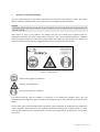
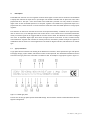
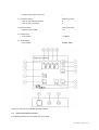
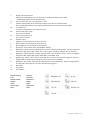
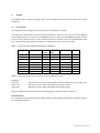
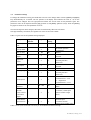
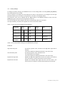
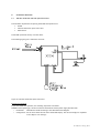
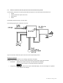
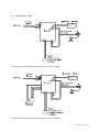
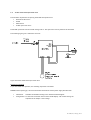
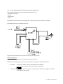
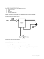
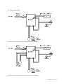
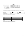
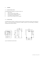
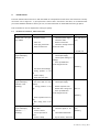
Page 1
- 1 -CRYOGENICS – VACUUM TECHNOLOGY – TECHMATIC - ENGINEERING - ISO 9001 / VCA**
01/12/2008
User’s Manual
Level Controller
Type DC206
Oct. 2008,rev.7,SvdP, pag.1-33
Quotations, transactions, and deliveries will be effected in accordance with the
DeMaCo Holland bv
T +31 (0)226 33 21 00
Oester 2
F +31 (0)226 33 21 11
Orgalime general conditions for the supply of mechanical, electrical and related products (October 1992). P.O Box 4
Chamber of Commerce registration number: 37079728.
NL 1723 ZG Noord-Scharwoude
E [email protected]
www.DeMaCo.nl
Contents
1.
OPERATOR’S SAFETY AND WELLBEING....................................................................... 3
2.
DESCRIPTION ....................................................................................................... 4
2.1
2.2
TYPE SPECIFICATION .................................................................................................. 4
DISPLAY AND OPERATING ELEMENTS ................................................................................... 6
3.
TECHNICAL DETAILS .............................................................................................. 8
4.
SETTINGS...........................................................................................................10
4.1
4.2
4.3
4.4
4.5
LEVEL SETTINGS .................................................................................................... 10
INSTALLATION SETTINGS ............................................................................................ 11
FACTORY SETTINGS ................................................................................................. 13
EXTRA ALARM ...................................................................................................... 14
GENERAL ALARM OUTPUT........................................................................................... 14
5. OPERATION ...........................................................................................................15
5.1
5.2
5.2.1
5.2.2
6.
CONNECTION OVERVIEW .......................................................................................18
6.1
6.2
6.3
6.4
6.5
6.6
6.7
6.8
6.9
7.
OPERATION MODE .................................................................................................. 15
START-UP .......................................................................................................... 16
STARTING UP IN “AUTOMATIC MODE”............................................................................... 16
STARTING UP IN “MANUAL OPERATION MODE” ...................................................................... 17
230 VAC MODEL WITH 230 VAC OPEN/CLOSE VALVE .............................................................. 18
230 VAC MODEL WITH 230 VAC OPEN/CLOSE VALVE AND OVERFLOW SAFETY DEVICE .............................. 19
OTHER 230 VAC MODELS .......................................................................................... 20
24 VDC MODEL WITH OPEN/CLOSE VALVE .......................................................................... 21
24 VDC MODEL WITH OPEN/CLOSE VALVE AND OVERFLOW SAFETY DEVICE........................................... 22
24 VDC MODEL WITH PROPORTIONAL VALVE........................................................................ 23
OTHER 24 VDC MODELS ........................................................................................... 24
TERMINAL BLOCKS .................................................................................................. 25
CABLE INFORMATION ............................................................................................... 26
ASSEMBLY ..........................................................................................................27
7.1
7.2
DC206 ASSEMBLY LOCATION ....................................................................................... 27
DC206 ASSEMBLY .................................................................................................. 27
8.
PROGRAMME DIAGRAM ..........................................................................................28
9.
DC206 FAILURES .................................................................................................29
9.1
9.2
9.3
DC206 LEVEL CONTROLLER, FAILURE OVERVIEW ................................................................... 29
LOW ALARM FAILURE ............................................................................................... 30
HIGH ALARM FAILURE ............................................................................................... 30
10. CE – DC206 LEVEL CONTROLLER DECLARATION ..........................................................31
Oct. 2008,rev.7, SvdP, pg. 2-32
1.
Operator’s safety and wellbeing
This user’s manual applies to the DeMaCo Holland bv Level Controller, type DC206 for liquids. The manual
applies to both the standard model of the DC206 as well as to models with custom software.
Remarks
The operator should read these instructions as soon as possible in order to understand how to operate the level
controller correctly.
With respect to injury to the operator, the dangers that may occur when using cryogenic media are
emphatically indicated. The sticker shown below is affixed to the areas on DeMaCo Holland bv equipment
where the operator comes into contact with cryogenic media. The symbols on the sticker warn the operator for
extreme cold and indicates that safety goggles and gloves with wrist protection must be worn.
Figure 1.1 Safety sticker
Wearing safety goggles is compulsory.
Warning: low temperatures.
Wearing safety gloves is compulsory.
This manual should at least be available for inspection at the department manager’s office. We also
recommend that this manual is copied, and kept at the workplace next to level controller in a binder or insert
folders.
We also advise you to read the DeMaCo safety instructions “Safety Guidelines for working with low temperature
media" thoroughly. These instructions give detailed information on working with cryogenic liquids. If several
copies of these instructions are required in order to create a safe workplace for the operator(s), you can make
more copies.
Oct. 2008,rev.7, SvdP, pg. 3-32
2.
Description
The DC206 level controller is a level regulator to which various types of sensors can be connected. The DC206 has
a display that indicates the liquid level in percentages. The DC206 is available with an open/close valve and a
proportional valve. The open / close valve model of the DC206 has a potential free relay contact to activate a
digital valve so that the DC206 operates as a two-point regulator. The DC206 has a proportional output for a
proportional valve, which sends out a current between 4 and 20 mA so that the DC206 operates as a single point
regulator.
The controller can also be set such that the fill valve can be operated manually. In addition to an upper and lower
limit for the fill level, a low and high alarm level can also be set. If one of these levels is exceeded (in automatic
mode), an acoustic signal will be triggered and the fill valve will be closed. This situation will remain unchanged
until reset. An adjustable digital input filter filters the signal from the level sensor in order to achieve steady
control behaviour. Together with a number of ancillary functions, this makes it possible to adjust the regulator in
combination with the sensor for various applications. DC stands for Digital Controller, 206 stands for the custom
type.
2.1
Type specification
A type plate has been affixed to the housing of the DC206 Level Controller, which specifies the type and options.
The supply voltage, project number, and software version are also specified. The abovementioned data is listed in
two lines on the type plate. Part of this data is recorded in code. An example of a type plate is given in figure 2.1.
Figure 2.1. DC206 type plate
The first line on the type plate specifies the DC206 settings. The second line contains coded information about the
supplied configuration.
Oct. 2008,rev.7, SvdP, pg. 4-32
Line 1. DC206 settings
1.
Supply voltage
The supply voltage is specified on the type plate. Possible supply voltages:
230 VAC 50 - 60 Hz
24 VDC
2.
Input power
The maximum input power is 10 Watt from the mains, excluding switched elements.
3.
4.
5.
Sensor input setting.
Code on type plate
4 - 20 mA
A
Valve output voltage
Code
230 VAC 50-60 Hz
01
24 VDC
03
Fuse type
The type of fuse is specified on the type plate.
Value:
230 VAC model
1 A (slow)
24 VDC model
4 A (slow)
Line 2. DC206 configuration
6.
Type indication
The type is directly specified on the type plate.
DC206 stands for Digital Controller
7.
8.
9.
Model
Code on type plate
Stand alone
A
Sensor input
This value indicates the connected sensor type:
Code on type plate
DS197 (DeMaCo capacitive sensor)
A
Pressure converter
B
Other sensors
O
PT100 input mA
Code on type plate
Not applied
X
PT100 applied
1
10. Valve output
Code on type plate
Fill valve type
No fill valve connected ex factory
X
Open/Close valve
E
Proportional valve
P
Other type
O
11. Analogue output signal
Analogue output signal not connected
Code on type plate
X
Oct. 2008,rev.7, SvdP, pg. 5-32
Analogue output signal connected
12. Parameter setting
1
Code on type plate
Start-up mode "Manual operation"
H
Start-up mode "Automatic"
A
13. Software release
Software version DC206
Code on type plate
A..Z
14. Identification
Order number
i.e. 080223
15. Serial number
Serial number
DC00000..99999
Figure 2.2. Overview of the DC206 operating elements
2.2
Display and operating elements
The following elements can be found on the control panel:
Oct. 2008,rev.7, SvdP, pg. 6-32
1.
Display with three positions.
Displays the instantaneous value, set values, error messages and other process values.
* Flashing digits indicate that the PT100 is active.
1A.
The level values are given in percentages; 0 – 100%.
2.
Symbolic representation of the various level settings in the form of four bullet points.
2A.
Low alarm level.
2B.
Start fill level (Lower limit)
2C.
Stop fill level (Upper limit)
2D
High alarm level
The corresponding indicators in the display indicate which level is being shown in the display.
Low Alarm is activated by a level below this value.
The fill valve is opened.
The fill valve is closed.
High Alarm is activated by a level above this value.
3.
[Value up] key. For increasing the values to be set.
4.
[Value down] key. For lowering the values to be set.
5.
[Select] key. This is used to select the parameter changes.
6.
[Open] key. This key is used for operating the fill valve in “manual operation mode”. The key is equipped
with a green LED, which lights up when the fill valve is open. *PT100 can close the valve if necessary.
7.
[Auto] key. Switches between “manual operation mode” and “automatic mode”. The key is equipped
with a green LED, which lights up when the DC206 is in automatic mode.
8.
[Restart] key. This is used to restart the DC206 after an alarm state has been triggered. The key is
equipped with an orange LED, which lights up when restart has to be initiated.
9.
[Reset] key. The acoustic alarm signal is accepted (switched off) with this key. The key is equipped with
an orange LED, which lights up if an alarm state has been triggered.
10.
Main switch
11.
Fuse holder 1
12.
Fuse holder 2
Waarde omhoog
– Value up
Auto
- Automatic
Waarde omlaag
– Value down
Restart
- Restart
Select
- Select
Herstel alarm
– Reset Alarm
Open
- Open
Oct. 2008,rev.7, SvdP, pg. 7-32
3.
Technical details
General functionality description
-
Digital controller, two point regulator for level control.
-
Proportional control
-
Two alarm points for low and high level
-
Easy to set and operate by means of the key pad (2.2)
-
Read out level in 0-100% of the application
-
Level free programmable
-
Alarm points free programmable
-
Main switch, two-pole design
-
Double fused
-
Connection for extra measuring sensor PT100 (Overflow)
Measuring inputs
Level sensor Input signal 4-20mA (Loop).
PT100 input switch point is adjustable between -150% º C and –199 º C.
Outputs
Open/Close valve control
Voltage free changeover contact: NO/NC, Max 230 VAC - 1A or 24 VDC – 3A
PT100 output
24 VDC, max 125mA
Low alarm
Linked to low-level setting.
Voltage free changeover contact: NO/NC, Max 24 VDC, 1 A
High alarm
Linked to high-level setting.
Voltage free changeover contact: NO/NC, Max 24 VDC, 1A
Automatic Current controller mode:
Automatic or manual operation.
Voltage free changeover contact: NO/NC, Max 24 VDC, 1A
Working range
Level between Upper Limit and Lower Limit.
Voltage free changeover contact: NO/NC, Max 24 VDC, 1A
Failure
General controller or sensor failure. See 8. Failures.
Voltage free changeover contact: NO/NC, Max 24 VDC, 1 A
Buzzer
Acoustic signal: 87 dB, at a distance of 1 metre
Power supply
The DC206 depends on the model to supply via the mains, 230 VAC 50/60 Hz, or via an external stabilised
power supply that 24 VDC >3A delivers.
Note:
When the DC206 is supplied with a 24 VDC source, the supply cable may not be any longer than 30
metres.
Oct. 2008,rev.7, SvdP, pg. 8-32
Accuracy
+/- 1% of the maximum value (100%).
Ambient conditions
The DC206 controller comes under class II (EN 6101, IEC 664).
Declaration of Conformity
See chapter 10 CE – declaration of the DC206 level controller.
Ambient temperatures
- 15 ºC to 50 ºC.
Climate resistance
When using the DC206 for applications in the open air, it is recommended to place it in a metal case to protect
it against direct sunlight and other weather influences. The maximum permissible relative humidity is 95%.
Height
The DC2006 may be applied at a maximum height of 2000m.
Ventilation
No specific requirements apply to the ventilation of the area in which the product is placed.
Cleaning
The outer part of the device can be cleaned with a damp cloth and non-caustic cleaning agent.
Housing
The DC206 has a plastic housing with a lockable lid and transparent polycarbonate window. Model IP 65.
Fuses
The DC206 is double fused.
Fuse type
:
Fuse value :
Glass fuse 4 x 20 mm, slow.
230 VAC model
:1A
24 VDC model
:4A
Oct. 2008,rev.7, SvdP, pg. 9-32
4.
Settings
The DC206 contains a number of settings. These can be changed by means of the front panel. The internal
settings are:
4.1
Level settings
For changing the level settings, the [Select] key has to be held down for 1 second.
The indicator for the selected level will then light up (position 1A, Figure 2.2). The level value can be adjusted
with the [Up] (position 1A, Figure 2.2) 3) and [Down] (position 4) keys. Press the [Select] key again to switch
to the next value that has to be set. Once the settings have been changed, these will be automatically taken
over and saved. After approximately 10 seconds, the regulator will revert to the control mode.
Table 4.1. gives a list of the possible settings that are displayed.
Description
Display indicator
Position
Maximum
number
values
DeMaCo setting Unit
2A
1 .. 99
2
%
2B
1 .. 99
--
%
2C
1 .. 99
--
%
2D
1 .. 99
98
%
•
Low alarm
i.e. 10
•
Lower limit
i.e. 40
Upper limit
i.e. 60
•
•
High alarm
i.e. 85
Table 4.1 List of the values that can be set for the four DC206 switch levels
Functions
Low alarm
Indicates the low level at which the DC206 sends off an alarm after the set delay time.
Lower limit
Indicates the level at which the DC206 starts filling the system.
Upper limit
Indicates the level at which the DC206 stops filling the system.
High level indicates the high level at which the DC206 triggers an alarm after the set delay time.
Recommendation
We recommend that you do not place the various levels too closely together and maintain a minimum variance
of 10% between the levels.
Oct. 2008,rev.7, SvdP, pg. 10-32
4.2
Installation settings
To change the installation setting, the DC206 has to be set to the change mode. Press the [Select] and [Open]
keys simultaneously for 2 seconds. The left position of the display then indicates the code (A – N) for the
parameter to be changed. The two right positions indicate the current value of this parameter again. The
parameter value can be adjusted with the [Up] (position 3) and [Down] (position 4) keys. Press the [Select]
key again to switch to the next parameter to be set.
Once the settings have been changed, these will be automatically taken over and saved.
After approximately 10 seconds, the regulator will revert to the control mode.
Table 4.2. gives a list of the possible settings displayed.
Description
Display
Range
DeMaCo
A
1 .. 99
1
Start-up mode
B
0 .. 1
1
Max. fill time
C
1 .. 99
30
D
0 .. 1
0
E
0 .. 1
0
indicator
Valve response
Unit
setting
Second
time
Low alarm
output
High alarm
output
0: manual operation
1: automatic
Minutes
0: make
2: break
0: make
2: break [activate /
deactivate
Auto output
F
0 .. 1
0
Input filter
G
1 .. 10
1
Working range
0: make
2: break
Second
0: make
H
0 .. 1
0
2: break [activate /
deactivate
0: < Low active
PT100 input A
I
0 .. 1
0
T measurement < T set
1: > High active
T measurement > T set
PT100
reference
J
50 .. 99
73
Fill valve
alarm
0: Failsafe, fill valve closes
function
in the event of
Limit value for overflow
1: Normal, remains open
L
0 .. 1
0
a low alarm
(alarm remains at high
level)
output
PT100/Restart
Input function
0: PT100 input
N
0 .. 1
0
1: Restart function
(alarm reset to higher level)
Table 4.2 List of the values that can be set for the DCDC206 installation settings
Oct. 2008,rev.7, SvdP, pg. 11-32
Functions:
Valve response time (A)
To prevent oscillation, the valve will be controlled at a level for the duration of the
set time the value exceeds. See 4.1 Level settings, Upper limit and Lower limit values.
Start-up mode (B) Start-up after switching the controller on in “Automatic mode” or “Manual operation
mode".
Max. Fill time (C)
If, when starting up the system in “Automatic mode”, the level in the application is below
the low level, filling will have begun during start-up. During this Maximum Fill Time, no
alarm signal will be triggered. When the set time has elapsed, and the level has not yet
reached the Minimum level value, a minimum alarm will be triggered. This time only
applies for the initial start-up when switching on the system. See 5.2.1 Starting up in
“Automatic mode”.
Low output (D)
Active when a low alarm state is triggered. Choice between a make or break contact.
High output (E)
Active when a high alarm state is triggered. Choose between a make or break contact
[circuit?].
Auto output (F)
Active in automatic mode. Choose between a make or break contact [circuit?].
Input filter (G)
During the set time, the input signal is filtered, which can create steadier control
behaviour.
Working range (H)
This signal indicates whether the level is between the Upper Limit and Lower Limit.
Choose between a make or break contact [circuit?].
PT100 output (I)
PT100 temperature is below the set value. Switch contact. Remarks: See 4.4 If the PT100
option has not been applied, set the parameter to “0”.
PT100 reference (J) When the value of the PT100 element exceeds this value, the Overflow Alarm will be
activated. This reference value is a temperature that falls between -150º and -199º C.
Since the display does not have enough characters, a value of 50 to 99 will be displayed.
Valve function (L) This defines the behaviour of the valve output during Low Alarm Failsafe: The valve closes
when a low alarm state is triggered, reset via the Restart key. Normal: The valve remains
open during when a low alarm state is triggered. If the setting = “0”, then the valve will
close in the event of a low alarm (the alarm is still maintained at a higher level). If the
setting = “1”, then the valve will remain open in the event of a low alarm (the alarm is
reset at a higher level).
PT100/Restart (N) This defines the function of the PT100 input. If no PT100 has been connected, the input
function can be restarted externally via this controller input after an alarm state has been
triggered.
Oct. 2008,rev.7, SvdP, pg. 12-32
4.3
Factory settings
To change the factory settings, the DC206 has to be set to the change mode. Press the [Select] and [Restart]
keys simultaneously for 3 seconds.
The left position of the display will then indicate the code for the parameter to be changed. The two right
positions indicate the current value of this parameter. The value on the display flashes.
The parameter value can be adjusted with the [Up] (position 3) and [Down] (position 4) keys. Press the
[Select] key again to switch to the next parameter to be set.
Once the settings have been changed, these will be automatically taken over and saved.
After approximately 10 seconds, the regulator will revert to the control mode.
Table 4.3. gives a list of the possible settings displayed.
Description
Display
High alarm
I
Range
Display
delay time
Repeat time
I
I
High alarm
Repeat time
Low alarm
1 .. 99
10
s
i.e. 10
1 .. 99
10
s
i.e. 30
1 .. 99
30
0.5 minute
i.e. 30
1 .. 99
30
0.5 minute
A
Low alarm
I
Unit
setting
i.e.10
delay time
DeMaCo
Table 4.3 List of the possible settings for the DC206 factory settings.
Functions
High alarm delay time
By entering a greater value, activation of the high alarm signal will be
delayed.
This can be applied for damping oscillations in the control loop.
Low alarm delay time
By entering a greater value, activation of the
low alarm signal will be delayed.
This can be applied for damping oscillations in the control loop.
Repeat time High alarm
Repeats the high alarm signal after the set time (value x 0.5 minutes)
after this has been accepted (switched off) by the operator.
Repeat time Low alarm
Repeats the minimum alarm signal after the set time (value x 0.5
minutes) after this has been accepted (switched off) by the operator.
Oct. 2008,rev.7, SvdP, pg. 13-32
4.4
Extra alarm
If the DC206 comes with an "extra alarm” option, it will have a special temperature sensor, type PT100,
connected to it. The PT100 only serves as an extra alarm. This option is separate from the normal level control
and is intended as an additional safety signal by means of a temperature measurement.
Example: Extra High alarm
Place the PT100 in the top part of the storage tank (above the Max Level of the level sensor) or in the flue gas
duct. If the liquid in the storage tank rises above the permissible level, the PT100 will cool down and,
depending on the set temperature, switch a relay. This signal can be relayed externally as an extra alarm
signal to warn the operator or to disable an application.
4.5
General Alarm output
As an option, the DC206 can be equipped with a potential free contact that indicates when the measured level
of the DS197 has reached a value outside the working range. Based on the relay contact, it is unclear whether
the measured level is too low or is indeed too high. The maximum contact rating is 24 VDC; the maximum
switching current is 1A. This relay is only suitable for ohmic loads.
Oct. 2008,rev.7, SvdP, pg. 14-32
5. Operation
The DC206 is operated by means of the touch controls on the front panel.
Figure 5.1. Overview of the DC206 operating elements
5.1
Operation mode
[Select]
(5) Hold down for 1 second. This allows the operator to change the level settings.
When
this
key
is
pressed
again,
the
next
parameter
appears.
After approximately 10 seconds, it returns to control mode.
[Select] [Open]
(5-6) Hold down simultaneously for 2 seconds. This allows the operator to change the
installation settings. After approximately 10 seconds, it returns to control mode.
Oct. 2008,rev.7, SvdP, pg. 15-32
[Select] [Restart]
(5-8) Hold down simultaneously for 3 seconds.
This allows the operator to change the factory settings.
After approximately 10 seconds, it returns to control mode.
[Value up]
(3) Increases the set value by 1. If this key is held down longer than 2 seconds,
this value will automatically increase.
[Value down]
(4) Decrease the set value by 1. If this key is held down longer than 2 seconds,
the value will automatically decrease.
[Auto]
(7) Touch control: Switches between “manual operation mode” and “automatic
mode”. The key is equipped with a green LED, which lights up when the DC206 is
in automatic mode.
[Open]
(6) Touch control: This key is used for activating the fill valve in “manual
operation mode”. The key is equipped with a green LED, which lights up when the
fill valve is open.
[Reset alarm]
() The acoustic alarm signal is accepted (switched off) with this. The key is
equipped with an orange LED, which lights up if an alarm state has been
triggered.
[Restart]
(8) This is used to restart the DC206 after an alarm state has been triggered.
The key is equipped with an orange LED, which lights up when restart has to. be
initiated.
5.2
Start-up
Switch on the main switch (10). The DC206 performs a self-test whereby the display "flashes” for the duration
of the self-test. When the self-test is completed, the display will indicate the current level value. The
controller will perform further actions depending on the mode it was started up in and the measured level.
5.2.1 Starting up in “Automatic mode”.
When the DC206 is started up in “automatic mode”, the fill valve is automatically opened after the self-test
and the filling of the application starts. The filling is done according to the set values. On the initial start-up,
the DC206 follows the set maximum filling time (see installation setting C) until the Upper limit level has been
reached. After a brief waiting time, the DC206 then switches over to the normal operation mode and is within
its working range (working range output is switched) and follows the set alarm delays (see factory settings).
Oct. 2008,rev.7, SvdP, pg. 16-32
5.2.2 Starting up in “Manual operation mode”
When the DC206 is started up in “manual operation mode”, after the self-test, the fill valve can be opened or
closed by operating the [Open] key (6). Filling is now effected as the fill valve is being opened by the operator.
The display indicates the current value and no acoustic alarm will be given for the set alarms.
In the event of a High Alarm, the LED in the [Open] key (6) will flash and the display will alternately read "100"
and “---“.
Attention: all settings and alarms will be ignored! Operation can now be switched over to automatic mode.
Oct. 2008,rev.7, SvdP, pg. 17-32
6.
Connection Overview
6.1
230 VAC model with 230 VAC open/close valve
The minimum requirements for putting the DC206 into operation are:
DC206
230 VAC solenoid for open/close valve
DS197 sensor
The DC206 is powered directly from the mains.
The following figure gives a schematic overview:
Figure 6.1 230 VAC model with open/close valve
Putting into operation
To put the DC206 into operation, the following steps have to be taken:
Caution: before opening up, the device must be switched off and the power supply disconnected!
•
Installation:
Assemble the DC206 according to the abovementioned diagram.
•
Configuration: Set the limit values with the aid of the DC206 display. The various settings are explained
in the chapter ‘User settings’.
Oct. 2008,rev.7, SvdP, pg. 18-32
6.2
230 VAC model with 230 VAC open/close valve and overflow safety device
The minimum requirements for putting the DC206 into operation in the abovementioned situation are:
DC206
230 VAC solenoid for open/close valve
DS197 sensor
PT100
The DC206 is powered directly from the mains.
The following figure gives a schematic overview:
Figure 6.2 230 VAC model with open/close valve and overflow safety device
Putting into operation
To put the DC206 into operation, the following steps have to be taken:
Caution: Before opening up, the device must be switched off and the power supply disconnected!
•
Installation:
Assemble the DC206 according to the abovementioned diagram.
Make sure that the jumper is internally switched to position A.
•
Configuration: Set the limit values with the aid of the DC206 display. The various settings are explained
in the chapter ‘User settings’.
Oct. 2008,rev.7, SvdP, pg. 19-32
6.3
Other 230 VAC models
Figure 6.3.1 230 VAC model with open/close valve and external display
Figure 6.3.2 230 VAC model with open/close valve and external display
Oct. 2008,rev.7, SvdP, pg. 20-32
6.4
24 VDC model with open/close valve
The minimum requirements for putting the DC206 into operation are:
External 24 VDC source
DC206
DS197 sensor
24 VDC open/close valve
The DC206 is powered from the 24 VDC voltage source. The open/close valve is powered via the DC206.
The following figure gives a schematic overview:
Figure 6.4 24 VAC model with open/close valve
Putting into operation
To put the DC206 into operation, the following steps have to be taken:
Caution: Before opening up, the device should be switched off and the power supply disconnected!
Installation:
Assemble the DC206 according to the abovementioned diagram.
Configuration: Set the limit values with the aid of the DC206 display. The various settings are
explained in the chapter ‘User settings’.
Oct. 2008,rev.7, SvdP, pg. 21-32
6.5
24 VDC model with open/close valve and overflow safety device.
The minimum requirements for putting the DC206 into operation are:
External 24 VDC source
DC206
DS197 sensor
PT100
The DC206 is powered from the 24 VDC voltage source. The open/close valve is powered via the 206.
The following figure gives a schematic overview:
Figure 6.5 24 VAC model with open/close valve and overflow safety device
Putting into operation
To put the DC206 into operation, the following steps have to be taken:
Caution: Before opening up, the device must be switched off and the power supply disconnected!
•
Installation:
Assemble the DC206 according to the abovementioned diagram.
Make sure that the jumper is internally switched to position B.
•
Configuration: Set the limit values with the aid of the DC206 display. The various settings are explained
in the chapter ‘User settings’.
Oct. 2008,rev.7, SvdP, pg. 22-32
6.6
24 VDC model with proportional valve.
The minimum requirements for putting the DC206 into operation are:
External 24 VDC source
DC206
DS197 sensor
Proportional adjustable valve
The DC206 is powered by an external 24 VDC source. The proportional valve is powered via the DC206.
The following figure gives a schematic overview:
Figure 6.6 24 VAC model with proportional valve
Putting into operation
To put the DC206 into operation, the following steps have to be taken:
Caution: Before opening up, the device must be switched off and the power supply disconnected!
•
Installation:
Assemble the DC206 according to the abovementioned diagram.
•
Configuration: Set the limit values with the aid of the DC206 display. The various settings are explained
in the chapter ‘User settings’.
Oct. 2008,rev.7, SvdP, pg. 23-32
6.7
Other 24 VDC models
Figure 6.7.1 24 VAC model with open/close valve and external display
Figure 6.7.1 24 VAC model with open/close valve and external display
Oct. 2008,rev.7, SvdP, pg. 24-32
6.8
Terminal blocks
The following table gives the function of the connections:
Connection
Name
PIN
Wire colour
1
Safety ground (PE)
2
Safety ground (PE)
3
230 VAC L
4
230 VAC L
5
230 VAC N
6
230 VAC N
7
Open / close valve (Common)
8
Open / close valve (Normally Open)
9
Open / close valve (Normally Closed)
10
Overflow safety device (Common)
11
Overflow safety device (Normally Open)
12
Overflow safety device (Normally Closed)
13
Proportional valve +
4
(Yellow)
14
PT100-H 24 VDC +
4
(Black)
15
PT100-H 24 VDC -
5
(Yellow/green)
16
PT100-1 (together with PT100-2 – 0-points
1
(Brown)
2
(White)
compensation in connection to wire resistance)
17
PT100-2 (together with PT100-1 – 0-points
compensation in connection to wire resistance)
18
PT100-3 (measuring signal via 1-3 or 2-3)
3
(Blue)
19
Sensor loop +
1
(Brown)
20
Ground
3
(Yellow/green)
21
Ground
22
Sensor loop -
2
(Green)
23
CAN ground
24
CANL out
25
CANH out
26
Proportional valve -
2
(Brown)
27
Ground
28
24 VDC in
29
0 VDC in
30
Ground
31
24 VDC out
7
(Red)
32
0 VDC out
3
(Green)
33
Alarm
34
Alarm
35
Ground
36
CAN ground
37
CANL in
38
CANH in
The following figure systematically shows the composition of the connectors as visible to the user:
Oct. 2008,rev.7, SvdP, pg. 25-32
The following table gives the jumper setting: This only applies to the PT100 power supply. If a PT100 is not
being used as an external alarm, then the position is not relevant.
The DC206 is delivered with the jumper set to the position A.
6.9
Cable information
Ref.
Description
Cable diameter
Vein diameter
Remarks
1
Power
6.0-8.0
0.75 mm2 PUR-CY
3 veins
2
Valve
6.0-8.0
0.75 mm2 PUR-CY
3 veins
3
Sensor
4.0-6.0
0.34 mm2 PUR-CY
3 veins + shielding
4
PT100 + H
4.0-6.0
0.34 mm2 PUR-CY
5 veins
5
External
8.0-11.0
0.5 mm2 PUR-CY
Max. 10 veins + shielding
For the first 3 references, the standard cable length is 5 meters.
Oct. 2008,rev.7, SvdP, pg. 26-32
7.
Assembly
7.1
DC206 assembly location
The DC206 should be assembled in a location such that it is:
►
easy to access
►
easy to read (not in direct sunlight)
►
does not protrude in passages or driveways
►
not exposed to vibrations and shocks
►
does not heat up through external irradiation
7.2
DC206 assembly
The DC206 should be mounted in accordance with the hole pattern as illustrated on the back of the housing (see
Figure 7.1). For the wiring connection, please refer to chapter 6, figures 6.1 up to and including 6.3. Optionally,
the DC206 can be secured to a DIN rail.
Figure 7.2 Dimensional characteristics
Oct. 2008,rev.7, SvdP, pg. 27-32
8.
Programme diagram
Definitions of the levels in the application.
---------------- High alarm
---------------- Upper limit
Controlled level
-------------- Lower limit
---------------- Low alarm
Oct. 2008,rev.7, SvdP, pg. 28-32
9.
DC206 failures
The most common failures that occur with the DC206 are incorporated into the failure overview below. The key
references refer to Figure 5.1. If you experience a failure that is not listed in the table, we recommend that
you contact DeMaCo Holland bv. Before you call, note the information on the DC206 and senor type plates.
This will enable our service department to help you quickly.
9.1
DC206 level controller, Failure Overview
Failure description
Possible cause
DC206 does not give ▶
No power supply
any readout
Action
Key
▶
Check the power supply
On / Out switch
▶
Check the cable
(10)
▶
Restore connection
Check the voltage and then
▶
Cable cut
▶
Loose plug connection
▶
▶
Fuses are burnt out
replace the fuses
(11)and (12)
DC206 gives an alarm
▶
Low alarm
signal and display
indicates “0”
▶
Reset acoustic signal
▶
Check liquid supply
▶
Check liquid drainage (i.e.
[Reset alarm]
leakage)
▶
Start up DC206 after
performing the checks
[Restart]
▶
Too much fluid drainage
▶
Filling pressure is too
low
▶
Tank is empty
▶
Valve does not open
▶
High alarm
signal and display
▶
Fill valve does not close ▶
indicates “100”
properly
DC206 gives an alarm
(flashing)
▶
▶
Filling pressure is too ▶
high
Reset acoustic signal
[Reset alarm]
Check liquid supply
Reduce response time
▶
Reduce max. filling level
▶
Start up DC206 after
See 4.2
performing the checks
[Restart]
▶
Valve response time is to
long
▶
Max. filling level is too
high
DC206 gives an alarm
▶
signal and display
indicates “--- ”
(flashing)
▶
Check the cable
On / Out switch
sensor cable
▶
Check the signal (4 – 20
(10)
▶
Sensor is defect
mA)
▶
Central processor is
▶
Call DeMaCo Holland bv
▶
Dry the sensor, observance
There is a kink in the
[Restart]
defect
▶
Sensor is damp
Oct. 2008,rev.7, SvdP, pg. 29-32
of the safety standards.
▶
PT100
has
been ▶
activated
Level measurement is A failure source is present in ▶
inaccurate
Check / correct level and
the PT100 sensor (if present)
Remove radiation source
the vicinity of the system,
which is emitting
electromagnetic radiation
Table 9.1 DC206 Level Controller Failure Overview
9.2
Low alarm failure
Setting parameter L valve function when there is a low alarm.
Failsafe mode:
The Failsafe function is applied to prevent the application from continuous overflow and demand for more
liquid due to unknown causes.
This function blocks the fill valve when a low alarm is present in order to prevent the application from
continuous filling when no operational personnel are present.
When this function has been activated and a low alarm is indicated, the controller should be restarted to
release the fill valve for automatic level control.
Normal mode:
This mode can be selected if a low alarm is indicated frequently and there is no danger of overflow. The low
alarm and corresponding contact will be reset if the level increases. In this mode, the fill valve remains open
and the application continues to fill. This can occur with longer supply lines and lower filling pressures. The
acoustic signal will be triggered and should be reset to acknowledge that an alarm has been triggered.
9.3
High alarm failure
In the event of a High alarm, the controller triggers an acoustic signal to announce this.
After the acoustic signal has been reset, the fill valve is released for automatic level control, the alarm output
will be reset.
If there is a high alarm, take the appropriate measures. If in doubt, always shut off the LN2 supply first.
Note: all alarms and level settings are ignored during manual operation mode.
Oct. 2008,rev.7, SvdP, pg. 30-32
10.
CE – DC206 level controller declaration
Manufacturer
DeMaCo Holland bv
Oester 2
NL-1723 HW Noord-Scharwoude
DeMaCo reference
DC206 Level Controller
Customer reference
Serial number / order number
The manufacturer hereby declares that the DC206 Level Controller complies with the stipulations of the following
directive(s):
EMC 2004/108/EC
Low Voltage Directive 2006/95/EC
and conforms with the following standard(s) or other normative documents:
Emission
Conducted emission:
EN 55011 (1998) + A1 (1999) + A2 (2002) (precedence)
and EN 55016-2-1 (2004)
Radiated emission:
EN 55011 (1998) + A1 (1999) + A2 (2002)
and EN 55016-2-3 (2004)
and EN 55011 (1998) + A1 (1999) +A2 (2002)
and EN55016-2-3 (2004)
Harmonics:
EN 61000-3-2 (2000)
Flicker:
EN 6100-3-3 (1995) + A1 (2001)
Immunity
Electro Static Discharges (ESD)
EN 61326 (1997) + A1 (1998) + A2 (2001) + A3 (2003) (precedence)
and EN 61000-4-2 (1995) + A1 (1998) + A2 (2001)
Radiated immunity:
EN 61326 (1997) + A1 (1998) + A2 (2001) + A3 (2003) (precedence)
and EN 61000-4-3 (2006)
Electrical Fast Transience (EFT)
EN 61326 (1997) + A1 (1998) + A2 (2001) + A3 (2003) (precedence)
and EN 61000-4-4 (1995) + A1 (2001) + A2 (2001)
Surges:
EN 61326 (1997) + A1 (1998) + A2 (2001) + A3 (2003) (precedence)
and EN 61000-4-5 (2007)
Conducted immunity:
EN 61326 (1997) + A1 (1998) + A2 (2001)
+ A3 (2003) (precedence)
and EN 61000-4-6 (1997) + A1 (2001)
Oct. 2008,rev.7, SvdP, pg. 31-32
Power supply
Voltage dips and variations
EN 61326 (1997) + A1 (1998) + A2 (2001) + A3 (2003) (precedence)
and EN 61000-4-11 (1994) + A1 (2001)
Safety:
EN 61010-1 : 2001
Place:
Noord-Scharwoude, the Netherlands
Date:
………………………
Name and function
………………………
………………………
Signature
………………………
Oct. 2008,rev.7, SvdP, pg. 32-32